EP3392993A1 - Electrostatic discharge protection circuit and device - Google Patents
Electrostatic discharge protection circuit and device Download PDFInfo
- Publication number
- EP3392993A1 EP3392993A1 EP17167153.0A EP17167153A EP3392993A1 EP 3392993 A1 EP3392993 A1 EP 3392993A1 EP 17167153 A EP17167153 A EP 17167153A EP 3392993 A1 EP3392993 A1 EP 3392993A1
- Authority
- EP
- European Patent Office
- Prior art keywords
- hardware
- comparator
- input
- electrostatic discharge
- controller
- Prior art date
- Legal status (The legal status is an assumption and is not a legal conclusion. Google has not performed a legal analysis and makes no representation as to the accuracy of the status listed.)
- Withdrawn
Links
Images

Classifications
-
- H—ELECTRICITY
- H02—GENERATION; CONVERSION OR DISTRIBUTION OF ELECTRIC POWER
- H02H—EMERGENCY PROTECTIVE CIRCUIT ARRANGEMENTS
- H02H9/00—Emergency protective circuit arrangements for limiting excess current or voltage without disconnection
- H02H9/04—Emergency protective circuit arrangements for limiting excess current or voltage without disconnection responsive to excess voltage
- H02H9/045—Emergency protective circuit arrangements for limiting excess current or voltage without disconnection responsive to excess voltage adapted to a particular application and not provided for elsewhere
- H02H9/046—Emergency protective circuit arrangements for limiting excess current or voltage without disconnection responsive to excess voltage adapted to a particular application and not provided for elsewhere responsive to excess voltage appearing at terminals of integrated circuits
-
- H—ELECTRICITY
- H10—SEMICONDUCTOR DEVICES; ELECTRIC SOLID-STATE DEVICES NOT OTHERWISE PROVIDED FOR
- H10D—INORGANIC ELECTRIC SEMICONDUCTOR DEVICES
- H10D89/00—Aspects of integrated devices not covered by groups H10D84/00 - H10D88/00
- H10D89/60—Integrated devices comprising arrangements for electrical or thermal protection, e.g. protection circuits against electrostatic discharge [ESD]
-
- H—ELECTRICITY
- H02—GENERATION; CONVERSION OR DISTRIBUTION OF ELECTRIC POWER
- H02H—EMERGENCY PROTECTIVE CIRCUIT ARRANGEMENTS
- H02H1/00—Details of emergency protective circuit arrangements
- H02H1/0007—Details of emergency protective circuit arrangements concerning the detecting means
Definitions
- the present disclosure relates to an electrostatic discharge protection circuit and a device having an electrostatic discharge protection circuit.
- Electrostatic discharge is a recurrent and common problem for devices, especially electronic devices. Static electricity can easily accumulate on a person (such as on the person's clothing) and on other objects. If a device, such as an electronic device, comes close to or in contact with the build-up of static electricity, an electrostatic discharge to the device can occur, which can damage the device, possibly catastrophically.
- an electrostatic discharge protection circuit for protecting a device from electrostatic discharge, the circuit comprising:
- Examples of embodiments provide protection from static electricity discharge for a device.
- Implementing the controller and the comparator in hardware means that the circuit operates much faster than an equivalent controller that is implemented in software for example.
- the threshold for the difference is zero.
- Other, typically small, values for the threshold may be used.
- the hardware controller is an integrated circuit.
- the hardware controller may be for example a microcontroller, an ASIC (application-specific integrated circuit) or a FPGA (field programmable gate array).
- the comparator is an op-amp or a comparator integrated circuit.
- an electronic device comprising:
- a method of controlling an electronic device comprising:
- a device such as an electronic device
- an electrostatic discharge to the device can occur, which can damage the device, possibly catastrophically, or at least can cause the device to "freeze” or "crash” (for example the operating system of the device ceases to operate and hangs).
- the device 10 may in general be any electronic device, including for example a smartphone, a desktop or laptop computer, a tablet computer, a television, a DVD or other media player, a set-top box, a gaming console, etc., etc.
- the device 10 has at least one processor 12.
- the processor 12 may be a "main" processor or CPU (central processing unit) of the device 10 or some other processor that is able to restart the device 10 as described further below.
- the device 10 has a main outer housing 14.
- the device 10 includes an electrostatic discharge protection circuit 16.
- the electrostatic discharge protection circuit 16 may be built into the device 10, for example located within the main outer housing 14, or may be provided as a separate unit which can be electrically connected to the device 10 (specifically, electrically connected to the processor 12 of the device 10).
- the electrostatic discharge protection circuit 16 includes a controller 18.
- the controller 18 is a hardware controller 18, that is, a controller that is implemented in hardware.
- a controller that is implemented in hardware operates much faster than an equivalent controller that is implemented in software for example.
- the hardware controller 18 may be provided as a single chip or integrated circuit.
- the hardware controller 18 may be for example a microcontroller, that is a CPU with memory and input(s) and output(s), which may also be referred to as a system-on-a-chip or SOC.
- the hardware controller 18 may be implemented by an ASIC (application-specific integrated circuit).
- the hardware controller 18 may be implemented by an FPGA (field programmable gate array).
- the hardware controller 18 has an output OUT which is electrically connected to an input IN of the processor 12 of the device 10.
- the controller 18 has overall control of operation of the device 10, including of the processor 12 of the device 10, and therefore has overall control of every process running on the device 10.
- the electrostatic discharge protection circuit 16 also includes a comparator 20.
- the comparator 20 is a hardware comparator 20, that is, a comparator that is implemented in hardware. A comparator that is implemented in hardware operates much faster than an equivalent comparator that is implemented in software for example.
- the hardware comparator 20 may be for example an op-amp voltage comparator. As another example, the hardware comparator 20 may be a comparator integrated circuit.
- the hardware comparator 20 has an output OUT which is electrically connected to an input IN of the hardware controller 18.
- the hardware comparator 20 has two inputs IN1, IN2. Voltages that are presented at the inputs IN1, IN2 of the hardware comparator 20 are compared and an output signal presented at the output OUT of the hardware comparator 20 if the difference between the voltages exceeds some threshold.
- the threshold may be zero or some other (typically small) value.
- the output signal presented at the output OUT of the hardware comparator 20 may be a reset signal which causes the controller 18 to send a restart signal to the input IN of the processor 12 of the device 10, which, in turn, causes the device 10 to restart.
- One input IN1 of the comparator 20 is electrically connected to some isolated or clear ground (or earth) 22. That is, the input IN1 of the comparator 20 is electrically connected to a ground 22 that is known will not be affected by an electrostatic discharge to the device 10, or at least is unlikely to be affected.
- the input IN1 of the comparator 20 may be electrically connected to an earth of the mains electricity supply.
- the input IN1 may be connected to the clear ground 22 via a series resistor.
- the other input IN2 of the comparator 20 is electrically connected to at least one portion 24 of the device 10 that is susceptible to electrostatic discharge.
- the other input IN2 of the comparator 20 may be electrically connected to several portions 24 of the device 10 that are susceptible to electrostatic discharge.
- a television set typically has a number of ports or connectors, such as for HDMI (High-Definition Multimedia Interface) cables, audio cables, USB (Universal Serial Bus), etc. These may have a grounded shield. This means that if a user attempts to plug in a cable and the user has an accumulated static charge, the accumulated static charge can flow to that ground, potentially damaging the television set.
- the input IN2 may be connected to the portion(s) 24 of the device 10 that is/are susceptible to electrostatic discharge via a series resistor(s).
- the comparator 20 Normally, when there is no electrostatic discharge, there is no voltage difference between these two inputs IN1, IN2 and the comparator 20 does not output any control or rest signal. If however static electricity flows to the portion 24 of the device 10 that is susceptible to electrostatic discharge and to which the second input pin IN2 of the comparator 20 is connected, there will be a voltage difference between the two inputs IN1, IN2 pin and the comparator 20 outputs a control or reset signal.
- the output control or reset signal of the comparator 20 is passed to the input IN of the controller 18, which in turn sends a restart signal to the input IN of the processor 12 of the device 10, which, in turn, causes the device 10 to restart.
- the voltages that are presented at the inputs IN1, IN2 of the comparator 20 are indicated by graphs 26, 28 respectively of voltage against time in Figure 2 .
- the voltage of the clear ground 22, which is presented at the first input IN1 is in substance zero at all times.
- the voltage of the portion 24 of the device 10 that is susceptible to electrostatic discharge, which is presented to the second input IN2 is shown as rising rapidly because static electricity has discharged to that portion 24. The voltage decays over time as the charge is dissipated.
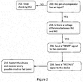
- FIG. 2 An example of a method is shown schematically in Figure 2 .
- it is checked whether the second input pin IN2 of the comparator 20 has an input. If no, then at 202 the check for whether the second input pin IN2 of the comparator 20 has an input is continued. If yes, then at 204 the voltages at the first and second input pins IN1, IN2 of the comparator 20 are compared. If there is a voltage difference (or at least a voltage difference above some threshold) at the first and second input pins IN1, IN2 of the comparator 20, then a RESET signal is sent to the controller 18. At 208, the controller 18 sends a RESTART signal to the device 10. At 210, the device 10 is restarted. Optionally, the device 10 also attempts to recover the crash or fail point.
- processor or processing system or circuitry referred to herein, including in particular the hardware controller may in practice be provided by a single chip or integrated circuit or plural chips or integrated circuits, optionally provided as a chipset, an application-specific integrated circuit (ASIC), field-programmable gate array (FPGA), etc.
- ASIC application-specific integrated circuit
- FPGA field-programmable gate array
Landscapes
- Engineering & Computer Science (AREA)
- Microelectronics & Electronic Packaging (AREA)
- Semiconductor Integrated Circuits (AREA)
- Elimination Of Static Electricity (AREA)
Abstract
Description
- The present disclosure relates to an electrostatic discharge protection circuit and a device having an electrostatic discharge protection circuit.
- Electrostatic discharge is a recurrent and common problem for devices, especially electronic devices. Static electricity can easily accumulate on a person (such as on the person's clothing) and on other objects. If a device, such as an electronic device, comes close to or in contact with the build-up of static electricity, an electrostatic discharge to the device can occur, which can damage the device, possibly catastrophically.
- According to a first aspect disclosed herein, there is provided an electrostatic discharge protection circuit for protecting a device from electrostatic discharge, the circuit comprising:
- a hardware controller for connection to a device which is to be protected from electrostatic discharge, the hardware controller being constructed and arranged to output a restart signal to a device connected to the hardware controller; and
- a hardware comparator, the hardware comparator having an output connected to an input of the hardware controller, a first input for connection to a clear ground, and a second input for connection to a portion of a device connected to the hardware controller that is susceptible to electrostatic discharge;
- the arrangement being such that a reset signal is produced at the output of the hardware comparator if a difference between a voltage at the first input of the hardware comparator and a voltage at the second input of the hardware comparator exceeds a threshold, the reset signal being received at the input of the hardware controller and causing the hardware controller to output a restart signal to a device connected to the hardware controller.
- Examples of embodiments provide protection from static electricity discharge for a device. Implementing the controller and the comparator in hardware means that the circuit operates much faster than an equivalent controller that is implemented in software for example.
- In an example, the threshold for the difference is zero. Other, typically small, values for the threshold may be used.
- In an example, the hardware controller is an integrated circuit. The hardware controller may be for example a microcontroller, an ASIC (application-specific integrated circuit) or a FPGA (field programmable gate array).
- In an example, the comparator is an op-amp or a comparator integrated circuit.
- According to a second aspect disclosed herein, there is provided an electronic device, the device comprising:
- at least one processor for controlling the device; and
- an electrostatic discharge protection circuit for protecting the device from electrostatic discharge, the circuit comprising:
- a hardware controller constructed and arranged to output a restart signal to the device processor; and
- a hardware comparator, the hardware comparator having an output connected to an input of the hardware controller, a first input for connection to a clear ground, and a second input electrically connected to a portion of the device that is susceptible to electrostatic discharge;
- the arrangement being such that a reset signal is produced at the output of the hardware comparator if a difference between a voltage at the first input of the hardware comparator and a voltage at the second input of the hardware comparator exceeds a threshold, the reset signal being received at the input of the hardware controller and causing the hardware controller to output a restart signal to the device processor to cause the device to restart.
- According to a third aspect disclosed herein, there is provided a method of controlling an electronic device, the method comprising:
- receiving at a first input of a hardware comparator a voltage from a clear ground;
- receiving at a second input of a hardware comparator a voltage from a portion of the device that is susceptible to electrostatic discharge;
- producing a reset signal at an output of the hardware comparator if a difference between the voltage at the first input of the hardware comparator and the voltage at the second input of the hardware comparator exceeds a threshold;
- receiving the reset signal at an input of a hardware controller; and
- in response to receiving the reset signal, the hardware controller outputting a restart signal to the device to cause the device to restart.
- To assist understanding of the present disclosure and to show how embodiments may be put into effect, reference is made by way of example to the accompanying drawings in which:
-
Figure 1 shows schematically an example of an electronic device having an electrostatic discharge protection circuit; and -
Figure 2 shows schematically an example of a method of operation of an electrostatic discharge protection circuit. - As mentioned, if a device, such as an electronic device, comes close to or in contact with a build-up of static electricity, an electrostatic discharge to the device can occur, which can damage the device, possibly catastrophically, or at least can cause the device to "freeze" or "crash" (for example the operating system of the device ceases to operate and hangs).
- Referring to
Figure 1 , there is shown schematically an example of anelectronic device 10. Thedevice 10 may in general be any electronic device, including for example a smartphone, a desktop or laptop computer, a tablet computer, a television, a DVD or other media player, a set-top box, a gaming console, etc., etc. Thedevice 10 has at least oneprocessor 12. Theprocessor 12 may be a "main" processor or CPU (central processing unit) of thedevice 10 or some other processor that is able to restart thedevice 10 as described further below. Thedevice 10 has a mainouter housing 14. - The
device 10 includes an electrostaticdischarge protection circuit 16. The electrostaticdischarge protection circuit 16 may be built into thedevice 10, for example located within the mainouter housing 14, or may be provided as a separate unit which can be electrically connected to the device 10 (specifically, electrically connected to theprocessor 12 of the device 10). - The electrostatic
discharge protection circuit 16 includes acontroller 18. Thecontroller 18 is ahardware controller 18, that is, a controller that is implemented in hardware. A controller that is implemented in hardware operates much faster than an equivalent controller that is implemented in software for example. Thehardware controller 18 may be provided as a single chip or integrated circuit. Thehardware controller 18 may be for example a microcontroller, that is a CPU with memory and input(s) and output(s), which may also be referred to as a system-on-a-chip or SOC. As another example, thehardware controller 18 may be implemented by an ASIC (application-specific integrated circuit). As another example, thehardware controller 18 may be implemented by an FPGA (field programmable gate array). Thehardware controller 18 has an output OUT which is electrically connected to an input IN of theprocessor 12 of thedevice 10. In some examples, thecontroller 18 has overall control of operation of thedevice 10, including of theprocessor 12 of thedevice 10, and therefore has overall control of every process running on thedevice 10. - The electrostatic
discharge protection circuit 16 also includes acomparator 20. Thecomparator 20 is ahardware comparator 20, that is, a comparator that is implemented in hardware. A comparator that is implemented in hardware operates much faster than an equivalent comparator that is implemented in software for example. Thehardware comparator 20 may be for example an op-amp voltage comparator. As another example, thehardware comparator 20 may be a comparator integrated circuit. - The
hardware comparator 20 has an output OUT which is electrically connected to an input IN of thehardware controller 18. Thehardware comparator 20 has two inputs IN1, IN2. Voltages that are presented at the inputs IN1, IN2 of thehardware comparator 20 are compared and an output signal presented at the output OUT of thehardware comparator 20 if the difference between the voltages exceeds some threshold. The threshold may be zero or some other (typically small) value. As will be discussed further below, the output signal presented at the output OUT of thehardware comparator 20 may be a reset signal which causes thecontroller 18 to send a restart signal to the input IN of theprocessor 12 of thedevice 10, which, in turn, causes thedevice 10 to restart. - One input IN1 of the
comparator 20 is electrically connected to some isolated or clear ground (or earth) 22. That is, the input IN1 of thecomparator 20 is electrically connected to aground 22 that is known will not be affected by an electrostatic discharge to thedevice 10, or at least is unlikely to be affected. For example, for adevice 10 that is powered by a mains electricity supply, the input IN1 of thecomparator 20 may be electrically connected to an earth of the mains electricity supply. As another example, there may be a portion of thedevice 10 that can be regarded as being electrically connected to a clear ground, such as a metal casing or the like of thedevice 10 which is normally in contact with an earth (such as a building floor or a shelf or other support that is electrically connected to earth). The input IN1 may be connected to theclear ground 22 via a series resistor. - The other input IN2 of the
comparator 20 is electrically connected to at least oneportion 24 of thedevice 10 that is susceptible to electrostatic discharge. The other input IN2 of thecomparator 20 may be electrically connected toseveral portions 24 of thedevice 10 that are susceptible to electrostatic discharge. As a specific example, a television set typically has a number of ports or connectors, such as for HDMI (High-Definition Multimedia Interface) cables, audio cables, USB (Universal Serial Bus), etc. These may have a grounded shield. This means that if a user attempts to plug in a cable and the user has an accumulated static charge, the accumulated static charge can flow to that ground, potentially damaging the television set. The input IN2 may be connected to the portion(s) 24 of thedevice 10 that is/are susceptible to electrostatic discharge via a series resistor(s). - Normally, when there is no electrostatic discharge, there is no voltage difference between these two inputs IN1, IN2 and the
comparator 20 does not output any control or rest signal. If however static electricity flows to theportion 24 of thedevice 10 that is susceptible to electrostatic discharge and to which the second input pin IN2 of thecomparator 20 is connected, there will be a voltage difference between the two inputs IN1, IN2 pin and thecomparator 20 outputs a control or reset signal. The output control or reset signal of thecomparator 20 is passed to the input IN of thecontroller 18, which in turn sends a restart signal to the input IN of theprocessor 12 of thedevice 10, which, in turn, causes thedevice 10 to restart. - The voltages that are presented at the inputs IN1, IN2 of the
comparator 20 are indicated bygraphs Figure 2 . As shown by thefirst graph 26, the voltage of theclear ground 22, which is presented at the first input IN1, is in substance zero at all times. On the other hand, the voltage of theportion 24 of thedevice 10 that is susceptible to electrostatic discharge, which is presented to the second input IN2, is shown as rising rapidly because static electricity has discharged to thatportion 24. The voltage decays over time as the charge is dissipated. - An example of a method is shown schematically in
Figure 2 . At 200, it is checked whether the second input pin IN2 of thecomparator 20 has an input. If no, then at 202 the check for whether the second input pin IN2 of thecomparator 20 has an input is continued. If yes, then at 204 the voltages at the first and second input pins IN1, IN2 of thecomparator 20 are compared. If there is a voltage difference (or at least a voltage difference above some threshold) at the first and second input pins IN1, IN2 of thecomparator 20, then a RESET signal is sent to thecontroller 18. At 208, thecontroller 18 sends a RESTART signal to thedevice 10. At 210, thedevice 10 is restarted. Optionally, thedevice 10 also attempts to recover the crash or fail point. - It will be understood that the processor or processing system or circuitry referred to herein, including in particular the hardware controller, may in practice be provided by a single chip or integrated circuit or plural chips or integrated circuits, optionally provided as a chipset, an application-specific integrated circuit (ASIC), field-programmable gate array (FPGA), etc.
- The examples described herein are to be understood as illustrative examples of embodiments of the invention. Further embodiments and examples are envisaged. Any feature described in relation to any one example or embodiment may be used alone or in combination with other features. In addition, any feature described in relation to any one example or embodiment may also be used in combination with one or more features of any other of the examples or embodiments, or any combination of any other of the examples or embodiments. Furthermore, equivalents and modifications not described herein may also be employed within the scope of the invention, which is defined in the claims.
Claims (12)
- An electrostatic discharge protection circuit for protecting a device from electrostatic discharge, the circuit comprising:a hardware controller for connection to a device which is to be protected from electrostatic discharge, the hardware controller being constructed and arranged to output a restart signal to a device connected to the hardware controller; anda hardware comparator, the hardware comparator having an output connected to an input of the hardware controller, a first input for connection to a clear ground, and a second input for connection to a portion of a device connected to the hardware controller that is susceptible to electrostatic discharge;the arrangement being such that a reset signal is produced at the output of the hardware comparator if a difference between a voltage at the first input of the hardware comparator and a voltage at the second input of the hardware comparator exceeds a threshold, the reset signal being received at the input of the hardware controller and causing the hardware controller to output a restart signal to a device connected to the hardware controller.
- An electrostatic discharge protection circuit according to claim 1, wherein the threshold for the difference is zero.
- An electrostatic discharge protection circuit according to claim 1 or claim 2, wherein the hardware controller is an integrated circuit.
- An electrostatic discharge protection circuit according to any of claims 1 to 3, wherein the comparator is an op-amp or a comparator integrated circuit.
- An electronic device, the device comprising:at least one processor for controlling the device; andan electrostatic discharge protection circuit for protecting the device from electrostatic discharge, the circuit comprising:a hardware controller constructed and arranged to output a restart signal to the device processor; anda hardware comparator, the hardware comparator having an output connected to an input of the hardware controller, a first input for connection to a clear ground, and a second input electrically connected to a portion of the device that is susceptible to electrostatic discharge;the arrangement being such that a reset signal is produced at the output of the hardware comparator if a difference between a voltage at the first input of the hardware comparator and a voltage at the second input of the hardware comparator exceeds a threshold, the reset signal being received at the input of the hardware controller and causing the hardware controller to output a restart signal to the device processor to cause the device to restart.
- A device according to claim 5, wherein the threshold for the difference is zero.
- A device according to claim 5 or claim 6, wherein the hardware controller is an integrated circuit.
- A device according to any of claims 5 to 7, wherein the comparator is an op-amp or a comparator integrated circuit.
- A method of controlling an electronic device, the method comprising:receiving at a first input of a hardware comparator a voltage from a clear ground;receiving at a second input of a hardware comparator a voltage from a portion of the device that is susceptible to electrostatic discharge;producing a reset signal at an output of the hardware comparator if a difference between the voltage at the first input of the hardware comparator and the voltage at the second input of the hardware comparator exceeds a threshold;receiving the reset signal at an input of a hardware controller; andin response to receiving the reset signal, the hardware controller outputting a restart signal to the device to cause the device to restart.
- A method according to claim 9, wherein the threshold for the difference is zero.
- A method according to claim 9 or claim 10, wherein the hardware controller is an integrated circuit.
- A method according to any of claims 9 to 11, wherein the comparator is an op-amp or a comparator integrated circuit.
Priority Applications (1)
| Application Number | Priority Date | Filing Date | Title |
|---|---|---|---|
| EP17167153.0A EP3392993A1 (en) | 2017-04-19 | 2017-04-19 | Electrostatic discharge protection circuit and device |
Applications Claiming Priority (1)
| Application Number | Priority Date | Filing Date | Title |
|---|---|---|---|
| EP17167153.0A EP3392993A1 (en) | 2017-04-19 | 2017-04-19 | Electrostatic discharge protection circuit and device |
Publications (1)
| Publication Number | Publication Date |
|---|---|
| EP3392993A1 true EP3392993A1 (en) | 2018-10-24 |
Family
ID=58671368
Family Applications (1)
| Application Number | Title | Priority Date | Filing Date |
|---|---|---|---|
| EP17167153.0A Withdrawn EP3392993A1 (en) | 2017-04-19 | 2017-04-19 | Electrostatic discharge protection circuit and device |
Country Status (1)
| Country | Link |
|---|---|
| EP (1) | EP3392993A1 (en) |
Cited By (1)
| Publication number | Priority date | Publication date | Assignee | Title |
|---|---|---|---|---|
| CN114598965A (en) * | 2020-12-07 | 2022-06-07 | 深圳市韶音科技有限公司 | A kind of audio power amplifier circuit and earphone |
Citations (3)
| Publication number | Priority date | Publication date | Assignee | Title |
|---|---|---|---|---|
| US20100315754A1 (en) * | 2009-06-11 | 2010-12-16 | Amazing Microelectronic Corp. | Transient voltage detection circuit |
| US20150070807A1 (en) * | 2013-09-12 | 2015-03-12 | Samsung Electronics Co., Ltd. | Method and apparatus for detecting electro static discharge in electronic device |
| US20170063080A1 (en) * | 2015-09-01 | 2017-03-02 | Seiko Epson Corporation | Static electricity protection circuit, semiconductor integrated circuit device, and electronic apparatus |
-
2017
- 2017-04-19 EP EP17167153.0A patent/EP3392993A1/en not_active Withdrawn
Patent Citations (3)
| Publication number | Priority date | Publication date | Assignee | Title |
|---|---|---|---|---|
| US20100315754A1 (en) * | 2009-06-11 | 2010-12-16 | Amazing Microelectronic Corp. | Transient voltage detection circuit |
| US20150070807A1 (en) * | 2013-09-12 | 2015-03-12 | Samsung Electronics Co., Ltd. | Method and apparatus for detecting electro static discharge in electronic device |
| US20170063080A1 (en) * | 2015-09-01 | 2017-03-02 | Seiko Epson Corporation | Static electricity protection circuit, semiconductor integrated circuit device, and electronic apparatus |
Cited By (2)
| Publication number | Priority date | Publication date | Assignee | Title |
|---|---|---|---|---|
| CN114598965A (en) * | 2020-12-07 | 2022-06-07 | 深圳市韶音科技有限公司 | A kind of audio power amplifier circuit and earphone |
| CN114598965B (en) * | 2020-12-07 | 2023-04-07 | 深圳市韶音科技有限公司 | Audio power amplifier circuit and earphone |
Similar Documents
| Publication | Publication Date | Title |
|---|---|---|
| CN107797955B (en) | Semiconductor device and method of operation thereof | |
| CN108701192B (en) | Secure semiconductor chip and method for operating the same | |
| CN102047519B (en) | Technique for removing in-rush current limiting and short circuit current limiting | |
| CN108475245B (en) | Plug and play device identification method and electronic device | |
| US9608429B2 (en) | Logging ESD events | |
| US6661631B1 (en) | Automatic latchup recovery circuit for fingerprint sensor | |
| US6819539B1 (en) | Method for circuit recovery from overstress conditions | |
| US9823679B2 (en) | Power delivery system with mitigation for radiation induced single event latch-up in microelectronic devices | |
| CN101510541A (en) | Method and apparatus for ESD protection | |
| US10903646B2 (en) | Electrostatic protection circuit | |
| US20180233905A1 (en) | Space efficient and power spike resistant esd power clamp with digitally timed latch | |
| US10060982B2 (en) | Detecting faults in motors and drives | |
| CN103972857A (en) | Fan control chip protection circuit | |
| US8602801B2 (en) | Electrical jack | |
| CN109560536B (en) | Control circuit and operation circuit | |
| JP6486158B2 (en) | Touch panel device | |
| US8510607B2 (en) | EFTB unit, USB device with the EFTB unit and method for resetting and reenumerating the USB device | |
| KR20150030394A (en) | Method and apparatus for detecting an electro static discharge on an electronic device | |
| JP6834083B2 (en) | Hot plug detection signal filtering | |
| US10606703B2 (en) | Monitoring circuit | |
| US20160149402A1 (en) | Usb esd protection circuit | |
| CN114786319A (en) | Anti-static method, intelligent equipment, device, equipment and storage medium | |
| US10418808B2 (en) | Detecting electrostatic discharge events in a computer system | |
| CN105633908B (en) | Electronic device and power protection method | |
| CN107240913A (en) | Electrostatic discharge (ESD) protection |
Legal Events
| Date | Code | Title | Description |
|---|---|---|---|
| PUAI | Public reference made under article 153(3) epc to a published international application that has entered the european phase |
Free format text: ORIGINAL CODE: 0009012 |
|
| STAA | Information on the status of an ep patent application or granted ep patent |
Free format text: STATUS: THE APPLICATION HAS BEEN PUBLISHED |
|
| AK | Designated contracting states |
Kind code of ref document: A1 Designated state(s): AL AT BE BG CH CY CZ DE DK EE ES FI FR GB GR HR HU IE IS IT LI LT LU LV MC MK MT NL NO PL PT RO RS SE SI SK SM TR |
|
| AX | Request for extension of the european patent |
Extension state: BA ME |
|
| STAA | Information on the status of an ep patent application or granted ep patent |
Free format text: STATUS: REQUEST FOR EXAMINATION WAS MADE |
|
| 17P | Request for examination filed |
Effective date: 20190424 |
|
| RBV | Designated contracting states (corrected) |
Designated state(s): AL AT BE BG CH CY CZ DE DK EE ES FI FR GB GR HR HU IE IS IT LI LT LU LV MC MK MT NL NO PL PT RO RS SE SI SK SM TR |
|
| GRAP | Despatch of communication of intention to grant a patent |
Free format text: ORIGINAL CODE: EPIDOSNIGR1 |
|
| STAA | Information on the status of an ep patent application or granted ep patent |
Free format text: STATUS: GRANT OF PATENT IS INTENDED |
|
| RIC1 | Information provided on ipc code assigned before grant |
Ipc: H05K 9/00 20060101AFI20210128BHEP Ipc: H01L 27/02 20060101ALI20210128BHEP Ipc: H02H 9/04 20060101ALI20210128BHEP Ipc: H02H 1/00 20060101ALI20210128BHEP |
|
| INTG | Intention to grant announced |
Effective date: 20210217 |
|
| STAA | Information on the status of an ep patent application or granted ep patent |
Free format text: STATUS: THE APPLICATION IS DEEMED TO BE WITHDRAWN |
|
| 18D | Application deemed to be withdrawn |
Effective date: 20210629 |