EP3392977A1 - Electrical box with stabilized terminal position accuracy - Google Patents
Electrical box with stabilized terminal position accuracy Download PDFInfo
- Publication number
- EP3392977A1 EP3392977A1 EP16874696.4A EP16874696A EP3392977A1 EP 3392977 A1 EP3392977 A1 EP 3392977A1 EP 16874696 A EP16874696 A EP 16874696A EP 3392977 A1 EP3392977 A1 EP 3392977A1
- Authority
- EP
- European Patent Office
- Prior art keywords
- connector
- insertion hole
- distribution center
- electrical distribution
- fixing member
- Prior art date
- Legal status (The legal status is an assumption and is not a legal conclusion. Google has not performed a legal analysis and makes no representation as to the accuracy of the status listed.)
- Granted
Links
Images


Classifications
-
- H—ELECTRICITY
- H01—ELECTRIC ELEMENTS
- H01R—ELECTRICALLY-CONDUCTIVE CONNECTIONS; STRUCTURAL ASSOCIATIONS OF A PLURALITY OF MUTUALLY-INSULATED ELECTRICAL CONNECTING ELEMENTS; COUPLING DEVICES; CURRENT COLLECTORS
- H01R13/00—Details of coupling devices of the kinds covered by groups H01R12/70 or H01R24/00 - H01R33/00
- H01R13/62—Means for facilitating engagement or disengagement of coupling parts or for holding them in engagement
- H01R13/627—Snap or like fastening
- H01R13/6271—Latching means integral with the housing
-
- H—ELECTRICITY
- H01—ELECTRIC ELEMENTS
- H01R—ELECTRICALLY-CONDUCTIVE CONNECTIONS; STRUCTURAL ASSOCIATIONS OF A PLURALITY OF MUTUALLY-INSULATED ELECTRICAL CONNECTING ELEMENTS; COUPLING DEVICES; CURRENT COLLECTORS
- H01R12/00—Structural associations of a plurality of mutually-insulated electrical connecting elements, specially adapted for printed circuits, e.g. printed circuit boards [PCB], flat or ribbon cables, or like generally planar structures, e.g. terminal strips, terminal blocks; Coupling devices specially adapted for printed circuits, flat or ribbon cables, or like generally planar structures; Terminals specially adapted for contact with, or insertion into, printed circuits, flat or ribbon cables, or like generally planar structures
- H01R12/70—Coupling devices
- H01R12/7005—Guiding, mounting, polarizing or locking means; Extractors
- H01R12/7011—Locking or fixing a connector to a PCB
- H01R12/7052—Locking or fixing a connector to a PCB characterised by the locating members
-
- B—PERFORMING OPERATIONS; TRANSPORTING
- B60—VEHICLES IN GENERAL
- B60R—VEHICLES, VEHICLE FITTINGS, OR VEHICLE PARTS, NOT OTHERWISE PROVIDED FOR
- B60R16/00—Electric or fluid circuits specially adapted for vehicles and not otherwise provided for; Arrangement of elements of electric or fluid circuits specially adapted for vehicles and not otherwise provided for
- B60R16/02—Electric or fluid circuits specially adapted for vehicles and not otherwise provided for; Arrangement of elements of electric or fluid circuits specially adapted for vehicles and not otherwise provided for electric constitutive elements
- B60R16/023—Electric or fluid circuits specially adapted for vehicles and not otherwise provided for; Arrangement of elements of electric or fluid circuits specially adapted for vehicles and not otherwise provided for electric constitutive elements for transmission of signals between vehicle parts or subsystems
- B60R16/0238—Electrical distribution centers
-
- B—PERFORMING OPERATIONS; TRANSPORTING
- B60—VEHICLES IN GENERAL
- B60R—VEHICLES, VEHICLE FITTINGS, OR VEHICLE PARTS, NOT OTHERWISE PROVIDED FOR
- B60R16/00—Electric or fluid circuits specially adapted for vehicles and not otherwise provided for; Arrangement of elements of electric or fluid circuits specially adapted for vehicles and not otherwise provided for
- B60R16/02—Electric or fluid circuits specially adapted for vehicles and not otherwise provided for; Arrangement of elements of electric or fluid circuits specially adapted for vehicles and not otherwise provided for electric constitutive elements
- B60R16/023—Electric or fluid circuits specially adapted for vehicles and not otherwise provided for; Arrangement of elements of electric or fluid circuits specially adapted for vehicles and not otherwise provided for electric constitutive elements for transmission of signals between vehicle parts or subsystems
- B60R16/0239—Electronic boxes
-
- H—ELECTRICITY
- H01—ELECTRIC ELEMENTS
- H01R—ELECTRICALLY-CONDUCTIVE CONNECTIONS; STRUCTURAL ASSOCIATIONS OF A PLURALITY OF MUTUALLY-INSULATED ELECTRICAL CONNECTING ELEMENTS; COUPLING DEVICES; CURRENT COLLECTORS
- H01R12/00—Structural associations of a plurality of mutually-insulated electrical connecting elements, specially adapted for printed circuits, e.g. printed circuit boards [PCB], flat or ribbon cables, or like generally planar structures, e.g. terminal strips, terminal blocks; Coupling devices specially adapted for printed circuits, flat or ribbon cables, or like generally planar structures; Terminals specially adapted for contact with, or insertion into, printed circuits, flat or ribbon cables, or like generally planar structures
- H01R12/70—Coupling devices
- H01R12/71—Coupling devices for rigid printing circuits or like structures
- H01R12/712—Coupling devices for rigid printing circuits or like structures co-operating with the surface of the printed circuit or with a coupling device exclusively provided on the surface of the printed circuit
- H01R12/716—Coupling device provided on the PCB
-
- H—ELECTRICITY
- H01—ELECTRIC ELEMENTS
- H01R—ELECTRICALLY-CONDUCTIVE CONNECTIONS; STRUCTURAL ASSOCIATIONS OF A PLURALITY OF MUTUALLY-INSULATED ELECTRICAL CONNECTING ELEMENTS; COUPLING DEVICES; CURRENT COLLECTORS
- H01R13/00—Details of coupling devices of the kinds covered by groups H01R12/70 or H01R24/00 - H01R33/00
- H01R13/46—Bases; Cases
- H01R13/502—Bases; Cases composed of different pieces
-
- H—ELECTRICITY
- H01—ELECTRIC ELEMENTS
- H01R—ELECTRICALLY-CONDUCTIVE CONNECTIONS; STRUCTURAL ASSOCIATIONS OF A PLURALITY OF MUTUALLY-INSULATED ELECTRICAL CONNECTING ELEMENTS; COUPLING DEVICES; CURRENT COLLECTORS
- H01R13/00—Details of coupling devices of the kinds covered by groups H01R12/70 or H01R24/00 - H01R33/00
- H01R13/46—Bases; Cases
- H01R13/502—Bases; Cases composed of different pieces
- H01R13/506—Bases; Cases composed of different pieces assembled by snap action of the parts
-
- H—ELECTRICITY
- H01—ELECTRIC ELEMENTS
- H01R—ELECTRICALLY-CONDUCTIVE CONNECTIONS; STRUCTURAL ASSOCIATIONS OF A PLURALITY OF MUTUALLY-INSULATED ELECTRICAL CONNECTING ELEMENTS; COUPLING DEVICES; CURRENT COLLECTORS
- H01R13/00—Details of coupling devices of the kinds covered by groups H01R12/70 or H01R24/00 - H01R33/00
- H01R13/62—Means for facilitating engagement or disengagement of coupling parts or for holding them in engagement
- H01R13/629—Additional means for facilitating engagement or disengagement of coupling parts, e.g. aligning or guiding means, levers, gas pressure electrical locking indicators, manufacturing tolerances
-
- H—ELECTRICITY
- H01—ELECTRIC ELEMENTS
- H01R—ELECTRICALLY-CONDUCTIVE CONNECTIONS; STRUCTURAL ASSOCIATIONS OF A PLURALITY OF MUTUALLY-INSULATED ELECTRICAL CONNECTING ELEMENTS; COUPLING DEVICES; CURRENT COLLECTORS
- H01R13/00—Details of coupling devices of the kinds covered by groups H01R12/70 or H01R24/00 - H01R33/00
- H01R13/62—Means for facilitating engagement or disengagement of coupling parts or for holding them in engagement
- H01R13/639—Additional means for holding or locking coupling parts together, after engagement, e.g. separate keylock, retainer strap
-
- H—ELECTRICITY
- H01—ELECTRIC ELEMENTS
- H01R—ELECTRICALLY-CONDUCTIVE CONNECTIONS; STRUCTURAL ASSOCIATIONS OF A PLURALITY OF MUTUALLY-INSULATED ELECTRICAL CONNECTING ELEMENTS; COUPLING DEVICES; CURRENT COLLECTORS
- H01R25/00—Coupling parts adapted for simultaneous co-operation with two or more identical counterparts, e.g. for distributing energy to two or more circuits
- H01R25/16—Rails or bus-bars provided with a plurality of discrete connecting locations for counterparts
- H01R25/161—Details
- H01R25/162—Electrical connections between or with rails or bus-bars
-
- H—ELECTRICITY
- H02—GENERATION; CONVERSION OR DISTRIBUTION OF ELECTRIC POWER
- H02B—BOARDS, SUBSTATIONS OR SWITCHING ARRANGEMENTS FOR THE SUPPLY OR DISTRIBUTION OF ELECTRIC POWER
- H02B1/00—Frameworks, boards, panels, desks, casings; Details of substations or switching arrangements
- H02B1/26—Casings; Parts thereof or accessories therefor
- H02B1/46—Boxes; Parts thereof or accessories therefor
-
- H—ELECTRICITY
- H01—ELECTRIC ELEMENTS
- H01R—ELECTRICALLY-CONDUCTIVE CONNECTIONS; STRUCTURAL ASSOCIATIONS OF A PLURALITY OF MUTUALLY-INSULATED ELECTRICAL CONNECTING ELEMENTS; COUPLING DEVICES; CURRENT COLLECTORS
- H01R13/00—Details of coupling devices of the kinds covered by groups H01R12/70 or H01R24/00 - H01R33/00
- H01R13/62—Means for facilitating engagement or disengagement of coupling parts or for holding them in engagement
- H01R13/629—Additional means for facilitating engagement or disengagement of coupling parts, e.g. aligning or guiding means, levers, gas pressure electrical locking indicators, manufacturing tolerances
- H01R13/62933—Comprising exclusively pivoting lever
- H01R13/62966—Comprising two pivoting levers
-
- H—ELECTRICITY
- H01—ELECTRIC ELEMENTS
- H01R—ELECTRICALLY-CONDUCTIVE CONNECTIONS; STRUCTURAL ASSOCIATIONS OF A PLURALITY OF MUTUALLY-INSULATED ELECTRICAL CONNECTING ELEMENTS; COUPLING DEVICES; CURRENT COLLECTORS
- H01R2107/00—Four or more poles
-
- H—ELECTRICITY
- H01—ELECTRIC ELEMENTS
- H01R—ELECTRICALLY-CONDUCTIVE CONNECTIONS; STRUCTURAL ASSOCIATIONS OF A PLURALITY OF MUTUALLY-INSULATED ELECTRICAL CONNECTING ELEMENTS; COUPLING DEVICES; CURRENT COLLECTORS
- H01R2201/00—Connectors or connections adapted for particular applications
- H01R2201/26—Connectors or connections adapted for particular applications for vehicles
Definitions
- the present invention relates to an electrical distribution center, and more particularly to an electrical distribution center having a terminal stabilizing terminal position assurance member.
- the electrical distribution center is the central control box for electric and electronic technology in modern automobiles.
- the distribution center of electrical energy in the automotive electrical system the current distribution in each circuit is rationally achieved in the automotive electronics.
- the electrical distribution center receives the status signals of each electronic device and sends a control signal to respond accordingly.
- the purpose of the present invention is to provide an electrical distribution center that stabilizes the terminal position degree in order to overcome the deficiencies of the prior art mentioned above and to ensure that the position of the internal terminal of the electrical distribution center does not change, effectively preventing the occurrence of damage during the installation operation and the transportation process.
- the terminal is misaligned due to misalignment of the terminals, which has the advantages of high mounting accuracy, simple structure, easy operation, and production cost.
- An electrical distribution center with a terminal stabilizing terminal position assurance (TPA) member includes a housing, and an electronic device, an upper fixing member, a printed circuit board, a lower fixing member, and a connector sequentially arranged in the housing from top to bottom.
- the upper fixing member is provided with a first insertion hole.
- the pin terminal of the electronic device is connected to the printed circuit board after passing through the first insertion hole.
- a connector mounting slot for fixing the connector is arranged on the lower fixing member.
- the connector installation slot is provided with the first a second insertion hole and a guiding member.
- the guiding member is sleeved with a terminal position assurance (TPA) member.
- the TPA member is provided with a third insertion hole opposite to the second insertion hole, and the connector pin. After the terminal is sequentially passed through the third and the second insertion holes, the TPA member is fixed along the guide rod member in the connector installation slot, and the pin terminal of the connector passes through the first insertion hole and then connects the printed circuit board
- the connector mounting groove is further provided with a pre-locking rod member.
- the fixed end of the pre-locking rod member is disposed in the connector mounting groove.
- the free end of the pre-locking rod member is provided with a terminal stabilizing TPA member to limit the position of the guide rod. Raised position on the piece.
- the shell includes a box cover and a bracket arranged vertically.
- the box cover is provided with a rotating shaft and a pull rod connecting the rotating shaft.
- the pull rod is provided with a hook portion
- the bracket is provided with a convex shaft opposite to the hook portion. The lever is rotated so that the hook catches the hook,
- the hook portion includes an upwardly curved first track and a downwardly curved second track.
- the first track is bent upwards to communicate with the second track, and the second track is bent downward to form an opening.
- the pull rod is in a semi-frame shape and is arranged along the outer wall of the cover. Both ends of the pull rod are respectively rotationally connected with a rotating shaft. Two ends of the pull rod are respectively provided with a hook portion.
- the connector mounting groove is provided in plurality.
- the lower fixing member is also provided with a printed circuit board mounting slot for fixing the printed circuit board.
- the upper fixing member and the lower fixing member are mutually locked.
- the lower fixing member and the connector are engaged with each other.
- the bracket is provided with an elastic clip for clamping the engine compartment of the automobile.
- the present invention has the following advantages:
- an electrical distribution center for stabilizing the terminal position includes a housing, an electronic device 2, an upper fixing member 3, a printed circuit board 4, and a lower fixing, which are sequentially disposed in the housing from top to bottom.
- the lower fixing member 5 and the connector 6 and the upper fixing member 3 and the lower fixing member 5 are engaged with each other.
- the lower fixing member 5 and the connector 6 are mutually interlocked.
- the upper fixing member 3 is provided with a first insertion hole, the pin of the electronic device 2.
- the terminal is connected to the printed circuit board 4 after passing through the first insertion hole.
- the lower fixing member 5 is provided with a printed circuit board mounting slot for fixing the printed circuit board 4 and a connector mounting groove 51 for fixing the connector 6.
- the second insertion hole 52 and the guiding member 53, the guiding member 53 is provided with a TPA member 7 as shown in Fig. 4 and Fig. 5 .
- the TPA member 7 is provided with a guiding member 53 opposite to the second insertion hole 52.
- the three insertion holes 71, the pin terminals of the connector 6 pass through the third insertion hole 71 and the second insertion hole 52 sequentially, and are fixed along the guiding member 53 along the guiding member 53 in the connector mounting groove 51.
- the pin terminal of the connector 6 is connected to the printed circuit board 4 after passing through the first insertion hole.
- the housing includes a cover 1 and a bracket 8 disposed up and down.
- the cover 1 is provided with a rotating shaft and a pull rod 11 for connecting the rotating shaft.
- the pull rod 11 is provided with a hook portion 12, and the bracket 8 is provided thereon.
- the convex shaft 81 facing the hook portion 12 rotates the pull rod 11 so that the hook portion 12 is engaged with the convex shaft 81.
- the hook portion 12 includes an upwardly curved first track 121 and a downwardly curved second track 122.
- the first track 121 is bent upwards to communicate with the second track 122.
- the second track 122 is bent downward to form an opening.
- two half-frame-shaped pull rods 11 are used and are disposed along the outer wall of the cover 1, and the rotation axis and the convex axis are four.
- Each of the pull rods 11 is rotatably connected to two ends of the pull rod 11 respectively.
- a hook portion 12 is respectively provided at both ends of the pull rod 11 and the pull rod 11 can be grasped by both hands and lifted upwards. At this time, the hook portion 12 is downward, and the opening contacts the convex shaft 81 on the bracket 8, and the convex shaft 81 follows The opening enters the second track 122, and then the pull rod 11 is pressed down, so that the convex shaft 81 enters the first track 121 from the second track 122 to complete the snap connection.
- the connector mounting groove 51 is further provided with a pre-locking rod member 54.
- the fixed end of the pre-locking rod member 54 is disposed in the connector mounting groove 51, and the free end of the pre-locking rod member 54 is configured to define the protrusion 55 of the TPA member 7 at the position of the guiding member 53.
- a plurality of connector mounting grooves 51 are provided.
- connector mounting grooves 51 are uniformly arranged, and four connectors 6 can be installed correspondingly.
- the bracket 8 is provided with an elastic clip for clamping within the engine compartment of the automobile, which facilitates installation of the electrical distribution center in the engine compartment of the vehicle.
- the electrical distribution center assembly process is as follows:
- the printed circuit board 4 has a circuit etched, and the electronic device 2 includes a fuse, a relay, etc.
- the printed circuit board 4 connects the power line to the fuse, the relay, and the connector 6 and the connector 6 to the inside of the car through the wiring harness. Power is supplied to the components to achieve a reasonable distribution of currents in the various circuits.
Landscapes
- Engineering & Computer Science (AREA)
- Mechanical Engineering (AREA)
- Power Engineering (AREA)
- Connection Or Junction Boxes (AREA)
- Details Of Connecting Devices For Male And Female Coupling (AREA)
Abstract
Description
- The present invention relates to an electrical distribution center, and more particularly to an electrical distribution center having a terminal stabilizing terminal position assurance member.
- In the design process of the vehicle's electrical/electronic distribution system, the electrical distribution center is the central control box for electric and electronic technology in modern automobiles. As the distribution center of electrical energy in the automotive electrical system, the current distribution in each circuit is rationally achieved in the automotive electronics. As an information processing center, the electrical distribution center receives the status signals of each electronic device and sends a control signal to respond accordingly.
- Due to the rapid development of the automotive market, customers are increasingly demanding the ease of installation of electrical distribution centers and the precision of mounting dimensions. The existing electrical distribution center standards are liable to cause poor positional deviations during the installation and operation of the assembly and during transportation. A new and higher specification structure for ensuring the terminal position is the trend for the development of the electrical distribution center in the future.
- The purpose of the present invention is to provide an electrical distribution center that stabilizes the terminal position degree in order to overcome the deficiencies of the prior art mentioned above and to ensure that the position of the internal terminal of the electrical distribution center does not change, effectively preventing the occurrence of damage during the installation operation and the transportation process. The terminal is misaligned due to misalignment of the terminals, which has the advantages of high mounting accuracy, simple structure, easy operation, and production cost.
- The purpose of the present invention can be achieved by the following technical solutions:
- An electrical distribution center with a terminal stabilizing terminal position assurance (TPA) member includes a housing, and an electronic device, an upper fixing member, a printed circuit board, a lower fixing member, and a connector sequentially arranged in the housing from top to bottom. The upper fixing member is provided with a first insertion hole. The pin terminal of the electronic device is connected to the printed circuit board after passing through the first insertion hole. A connector mounting slot for fixing the connector is arranged on the lower fixing member. The connector installation slot is provided with the first a second insertion hole and a guiding member. The guiding member is sleeved with a terminal position assurance (TPA) member. The TPA member is provided with a third insertion hole opposite to the second insertion hole, and the connector pin. After the terminal is sequentially passed through the third and the second insertion holes, the TPA member is fixed along the guide rod member in the connector installation slot, and the pin terminal of the connector passes through the first insertion hole and then connects the printed circuit board.
- The connector mounting groove is further provided with a pre-locking rod member. The fixed end of the pre-locking rod member is disposed in the connector mounting groove. The free end of the pre-locking rod member is provided with a terminal stabilizing TPA member to limit the position of the guide rod. Raised position on the piece.
- The shell includes a box cover and a bracket arranged vertically. The box cover is provided with a rotating shaft and a pull rod connecting the rotating shaft. The pull rod is provided with a hook portion, and the bracket is provided with a convex shaft opposite to the hook portion. The lever is rotated so that the hook catches the hook,
- The hook portion includes an upwardly curved first track and a downwardly curved second track. The first track is bent upwards to communicate with the second track, and the second track is bent downward to form an opening.
- The pull rod is in a semi-frame shape and is arranged along the outer wall of the cover. Both ends of the pull rod are respectively rotationally connected with a rotating shaft. Two ends of the pull rod are respectively provided with a hook portion.
- The connector mounting groove is provided in plurality.
- The lower fixing member is also provided with a printed circuit board mounting slot for fixing the printed circuit board.
- The upper fixing member and the lower fixing member are mutually locked.
- The lower fixing member and the connector are engaged with each other.
- The bracket is provided with an elastic clip for clamping the engine compartment of the automobile.
- Compared with the prior art, the present invention has the following advantages:
- 1) In the present invention, a TPA member for guiding the position of the terminal and a corresponding guide member are provided. When the connector is installed, the pin terminal of the connector passes through the third insertion hole and the second insertion hole in sequence, and then the position stability is stable. The piece is fixed along the guide bar member in the connector installation slot, which can effectively ensure the precision of the paired installation operation. After the connector is fixed, the connector terminal is simultaneously fixed by the first insertion hole and the second insertion hole, which can effectively prevent the terminal position from shifting during the transportation process, so as to improve the precision of the position of the terminals in the electrical distribution center and adapt to the trend of future customer demands.
- 2) In the present invention, the electronic device, the upper fixing member, the printed circuit board, the lower fixing member and the connector are distributedly assembled. The printed circuit board mounting slot fixes the position of the printed circuit board, and the assembly is convenient and easy to disassemble and maintain.
- 3) In the present invention, the housing uses a box cover and a bracket which are interlocked with each other. In particular, this connection method adopts a hooking part and a convex shaft to clamp the connection. The first track and the second track on the hook part are defined to move the convex shaft. The track and the connection method can ensure the stable connection between the box cover and the bracket. The draw bar is in a semi-frame shape, which is convenient for the operator to operate and the design is more humane.
- 4) The connector mounting groove is also provided with a pre-locking member, which can limit the TPA member on the guide member, prevent the TPA member from falling off, and the structure is more stable and reliable.
- 5) A plurality of connector installation slots are provided, corresponding to which a plurality of connectors can be provided, and a large number of wiring harnesses can be connected to the circuit on the printed circuit board through connectors, which is suitable for producing multifunctional electrical distribution centers.
-
-
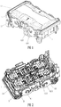
Fig. 1 is a schematic diagram of the external structure of the present invention; -
Fig. 2 is a schematic diagram of the internal structure of the present invention; -
Fig. 3 is a schematic view of an internal cross section of the present invention; -
Fig. 4 is a schematic structural diagram of a TPA member; -
Fig. 5 is a schematic view of installation of a TPA member in a connector mounting groove of a lower fixing member; -
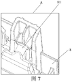
Fig. 6 is a schematic structural view of the bracket; -
Fig. 7 is a partial enlarged view of A inFig. 6 . -
- 1
- cover,
- 11
- pull rod;
- 12
- hook portion;
- 121
- first track;
- 122
- second track;
- 2
- electronic device;
- 3
- upper fixing member;
- 4
- printed circuit board;
- 5
- lower fixing member;
- 51
- connector mounting groove;
- 52
- second insertion hole;
- 53
- guiding member;
- 54
- pre-locking rod member;
- 55
- protrusion;
- 6
- connector;
- 7
- TPA member
- 71
- third insertion hole;
- 8
- bracket; and
- 81
- convex shaft.
- The present invention will be described in detail below with reference to the accompanying drawings and specific embodiments.
- This embodiment is implemented on the premise of the technical solution of the present invention, and a detailed implementation manner and a specific operation process are given. However, the scope of protection of the present invention is not limited to the following embodiments.
- As shown in
Fig. 1, Fig. 2 , andFig. 3 , an electrical distribution center for stabilizing the terminal position includes a housing, anelectronic device 2, anupper fixing member 3, a printed circuit board 4, and a lower fixing, which are sequentially disposed in the housing from top to bottom. Thelower fixing member 5 and theconnector 6 and the upper fixingmember 3 and thelower fixing member 5 are engaged with each other. Thelower fixing member 5 and theconnector 6 are mutually interlocked. Theupper fixing member 3 is provided with a first insertion hole, the pin of theelectronic device 2. The terminal is connected to the printed circuit board 4 after passing through the first insertion hole. Thelower fixing member 5 is provided with a printed circuit board mounting slot for fixing the printed circuit board 4 and aconnector mounting groove 51 for fixing theconnector 6. The second insertion hole 52 and the guidingmember 53, the guidingmember 53 is provided with aTPA member 7 as shown inFig. 4 andFig. 5 . TheTPA member 7 is provided with a guidingmember 53 opposite to the second insertion hole 52. The threeinsertion holes 71, the pin terminals of theconnector 6 pass through thethird insertion hole 71 and the second insertion hole 52 sequentially, and are fixed along the guidingmember 53 along the guidingmember 53 in theconnector mounting groove 51. The pin terminal of theconnector 6 is connected to the printed circuit board 4 after passing through the first insertion hole. - As shown in
Fig. 1 andFig. 6 , the housing includes acover 1 and abracket 8 disposed up and down. Thecover 1 is provided with a rotating shaft and apull rod 11 for connecting the rotating shaft. Thepull rod 11 is provided with ahook portion 12, and thebracket 8 is provided thereon. Theconvex shaft 81 facing thehook portion 12 rotates thepull rod 11 so that thehook portion 12 is engaged with theconvex shaft 81. - The
hook portion 12 includes an upwardly curvedfirst track 121 and a downwardly curvedsecond track 122. Thefirst track 121 is bent upwards to communicate with thesecond track 122. Thesecond track 122 is bent downward to form an opening. - In the present embodiment, two half-frame-shaped
pull rods 11 are used and are disposed along the outer wall of thecover 1, and the rotation axis and the convex axis are four. Each of thepull rods 11 is rotatably connected to two ends of thepull rod 11 respectively. Ahook portion 12 is respectively provided at both ends of thepull rod 11 and thepull rod 11 can be grasped by both hands and lifted upwards. At this time, thehook portion 12 is downward, and the opening contacts theconvex shaft 81 on thebracket 8, and theconvex shaft 81 follows The opening enters thesecond track 122, and then thepull rod 11 is pressed down, so that theconvex shaft 81 enters thefirst track 121 from thesecond track 122 to complete the snap connection. - As shown in
Fig. 5 , theconnector mounting groove 51 is further provided with apre-locking rod member 54. The fixed end of thepre-locking rod member 54 is disposed in theconnector mounting groove 51, and the free end of thepre-locking rod member 54 is configured to define the protrusion 55 of theTPA member 7 at the position of the guidingmember 53. - A plurality of
connector mounting grooves 51 are provided. - In this embodiment, four
connector mounting grooves 51 are uniformly arranged, and fourconnectors 6 can be installed correspondingly. - The
bracket 8 is provided with an elastic clip for clamping within the engine compartment of the automobile, which facilitates installation of the electrical distribution center in the engine compartment of the vehicle. - The electrical distribution center assembly process is as follows:
- Step 1: the
cover 1, theelectronic device 2, the upper fixingmember 3, the printed circuit board 4, and thelower fixing member 5 are sequentially assembled, and the printed circuit board 4 is connected to the power line; - Step 2: The
TPA member 7 is set on the guidingmember 53 of theconnector mounting groove 51, and the position of theTPA member 7 is defined by thepre-locking rod member 54. At this time, theTPA member 7 and theconnector mounting groove 51 The distance between the bottom surface is 8 to 10mm, for example 9 mm, this distance forms the space for stabilizing the terminal position of theconnector 6 when theconnector 6 is installed; - Step 3: The terminal of the
connector 6 is inserted into thethird insertion hole 71, and theTPA member 7 is pushed down until theconnector 6 is engaged with thelower fixing member 5. At this time, theTPA member 7 is tightly attached to the connector. The bottom of theconnector mounting groove 51, the terminal of theconnector 6 through the second insertion hole 52 opposite the third insertion hole to the 71 is connected printed circuit board mounting groove; - Step 4: The
connector 6 is connected to the wire harness, thebracket 8 is in contact with thecover 1 from the side of theconnector 6, thebracket 8 is provided with a wire harness port for harness wire access, and thepull rod 11 causes thebracket 8 and thecover 1 to be snapped to complete the assembly. - The working principle of the electrical distribution center: the printed circuit board 4 has a circuit etched, and the
electronic device 2 includes a fuse, a relay, etc. The printed circuit board 4 connects the power line to the fuse, the relay, and theconnector 6 and theconnector 6 to the inside of the car through the wiring harness. Power is supplied to the components to achieve a reasonable distribution of currents in the various circuits.
Claims (10)
- An electrical distribution center configured to stabilize a position of a terminal, comprising:a housing containing an electronic device (2), an upper fixing member (3), and a printed circuit board (4), which are sequentially arranged in the housing in the order listed;a lower fixing member (5);a connector (6), wherein the upper fixing member (3) is provided with a first insertion hole, and a pin terminal of the electronic device (2) passes through the first insertion hole and connects the printed circuit board (4), said printed circuit board (4) provided with a connector mounting groove (51) for fixing the connector (6) on the lower fixing member (5), wherein a second insertion hole (52) is provided in the connector mounting groove (51), anda guiding member (53) having a TPA member (7) sleeved thereon,wherein the TPA member (7) is provided with the second insertion hole (52) opposite to the guiding member (53) and a third insertion hole (71) opposite the second insertion hole (52), the pin terminal of the connector (6) passes through the third insertion hole (71) and the second insertion hole (52) in sequence, and is guided along with the TPA member (7), said guiding member (53) is fixed in the connector mounting groove (51), and wherein the pin terminal of the connector (6) passes through the first insertion hole and then connects the printed circuit board (4).
- The electrical distribution center according to claim 1, wherein a pre-locking rod member (54) is further provided in the connector mounting groove (51), wherein a fixed end of the lower fixing member (5) is provided in the connector mounting groove (51), and wherein a free end of the pre-locking rod member (54) is provided with a protrusion (55) for limiting a position of the TPA member (7) on the guiding member (53).
- The electrical distribution center according to claim 1, wherein the housing comprises a cover (1) and a bracket (8), wherein the cover (1) is provided with a rotating shaft and a pull rod (11) for connecting the rotating shaft, wherein a hook portion (12) is arranged on the pull rod (11), and wherein a convex shaft (81) opposite to the hook portion (12) is provided on the bracket (8) for rotation, said pull rod (11) causes the hook portion (12) to be engaged with the convex shaft (81).
- The electrical distribution center according to claim 3, wherein the hook portion (12) comprises a first track (121) bent upwards and a second track (122) bent downwards, wherein the first track (121) is bent upwards to communicate with the second track (122), and wherein the second track (122) is bent downward to form an opening.
- The electrical distribution center according to claim 3, wherein the pull rod (11) is in a semi-frame shape and is arranged along an outer wall of the cover (1) and wherein the rotating shaft is rotatably connected with a shaft, and two hook portions are respectively disposed at both ends of the pull rod (11).
- The electrical distribution center according to claim 1, wherein said connector mounting groove (51) is provided in plurality.
- The electrical distribution center according to claim 1, wherein the lower fixing member (5) is further provided with a printed circuit board (4) mounting slot for fixing the printed circuit board (4).
- The electrical distribution center according to claim 1, wherein the upper fixing member (3) and the lower fixing member (5) are engaged with each other.
- The electrical distribution center according to claim 1, wherein the lower fixing member (5) and the connector (6) are connected to each other.
- The electrical distribution center according to claim 3, wherein the bracket (8) is provided with an elastic clip for clamping the electrical distribution center within an engine compartment of an automobile.
Applications Claiming Priority (2)
| Application Number | Priority Date | Filing Date | Title |
|---|---|---|---|
| CN201510957810.0A CN106898905B (en) | 2015-12-18 | 2015-12-18 | A kind of electrical box of stable terminal position degree |
| PCT/CN2016/106734 WO2017101639A1 (en) | 2015-12-18 | 2016-11-22 | Electrical box with stabilized terminal position accuracy |
Publications (3)
| Publication Number | Publication Date |
|---|---|
| EP3392977A1 true EP3392977A1 (en) | 2018-10-24 |
| EP3392977A4 EP3392977A4 (en) | 2019-11-20 |
| EP3392977B1 EP3392977B1 (en) | 2024-07-24 |
Family
ID=59055724
Family Applications (1)
| Application Number | Title | Priority Date | Filing Date |
|---|---|---|---|
| EP16874696.4A Active EP3392977B1 (en) | 2015-12-18 | 2016-11-22 | Electrical box with stabilized terminal position accuracy |
Country Status (5)
| Country | Link |
|---|---|
| US (1) | US10256555B2 (en) |
| EP (1) | EP3392977B1 (en) |
| KR (1) | KR102110062B1 (en) |
| CN (1) | CN106898905B (en) |
| WO (1) | WO2017101639A1 (en) |
Families Citing this family (9)
| Publication number | Priority date | Publication date | Assignee | Title |
|---|---|---|---|---|
| US10923851B2 (en) * | 2016-10-04 | 2021-02-16 | Ampfibian Holdings Pty Ltd | Outdoor electrical plug and socket cover |
| CN108075254B (en) * | 2017-07-12 | 2024-03-19 | 盐城世明电子器件有限公司 | electrical connector |
| CN107257604B (en) * | 2017-08-14 | 2019-06-04 | 安徽江淮汽车集团股份有限公司 | A kind of automobile electrical box provided |
| CN109193196B (en) * | 2018-09-27 | 2024-02-23 | 郑州云海信息技术有限公司 | Labor-saving double-support type module buckling device |
| CN111371004B (en) * | 2018-12-25 | 2022-03-29 | 李尔公司 | Electrical assembly for preventing incorrect installation |
| CN111031670A (en) * | 2019-12-10 | 2020-04-17 | 芜湖宏景电子股份有限公司 | A vehicle wireless charging module wiring harness connector structure |
| US10971856B1 (en) | 2020-01-30 | 2021-04-06 | Aptiv Technologies Limited | Lever-type electrical connector |
| CN112590679A (en) * | 2020-12-18 | 2021-04-02 | 重庆千能实业有限公司 | Automobile central control box mounting bracket |
| CN114459402B (en) * | 2022-01-20 | 2024-05-10 | 上海轩田智能科技股份有限公司 | Pin position degree detection device |
Family Cites Families (10)
| Publication number | Priority date | Publication date | Assignee | Title |
|---|---|---|---|---|
| AU524109B2 (en) * | 1978-05-30 | 1982-09-02 | Amp Incorporated | Electrical junction box |
| CN2562426Y (en) * | 2002-07-11 | 2003-07-23 | 富士康(昆山)电脑接插件有限公司 | Plug seat connector |
| US7931479B1 (en) * | 2009-11-17 | 2011-04-26 | Delphi Technologies, Inc. | Bussed electrical center with combination electrical and mechanical connection |
| KR101668487B1 (en) * | 2010-02-22 | 2016-10-21 | 타이코에이엠피 주식회사 | Joint connector assembly |
| JP2012165590A (en) * | 2011-02-08 | 2012-08-30 | Sumitomo Wiring Syst Ltd | Electric connection box |
| JP5750335B2 (en) * | 2011-07-28 | 2015-07-22 | 矢崎総業株式会社 | Electrical junction box |
| US8926344B2 (en) * | 2013-01-16 | 2015-01-06 | Delphi Technologies, Inc. | Electrical distribution center assembly having a terminal stabilizer plate |
| US20150016077A1 (en) * | 2013-07-15 | 2015-01-15 | Delphi Technologies, Inc. | Electrical center for a vehicle |
| CN203775565U (en) * | 2014-04-10 | 2014-08-13 | 德尔福中央电气(上海)有限公司 | Rod type quick-installation central electrical box |
| CN205303799U (en) * | 2015-12-18 | 2016-06-08 | 德尔福中央电气(上海)有限公司 | Stabilize electric box of terminal position degree |
-
2015
- 2015-12-18 CN CN201510957810.0A patent/CN106898905B/en active Active
-
2016
- 2016-11-22 WO PCT/CN2016/106734 patent/WO2017101639A1/en not_active Ceased
- 2016-11-22 EP EP16874696.4A patent/EP3392977B1/en active Active
- 2016-11-22 US US16/062,398 patent/US10256555B2/en active Active
- 2016-11-22 KR KR1020187020454A patent/KR102110062B1/en active Active
Also Published As
| Publication number | Publication date |
|---|---|
| US10256555B2 (en) | 2019-04-09 |
| CN106898905B (en) | 2019-04-12 |
| CN106898905A (en) | 2017-06-27 |
| EP3392977A4 (en) | 2019-11-20 |
| WO2017101639A1 (en) | 2017-06-22 |
| US20180358724A1 (en) | 2018-12-13 |
| EP3392977B1 (en) | 2024-07-24 |
| KR20190077242A (en) | 2019-07-03 |
| KR102110062B1 (en) | 2020-05-12 |
Similar Documents
| Publication | Publication Date | Title |
|---|---|---|
| US10256555B2 (en) | Electrical distribution center with terminal stabilizing terminal position assurance member | |
| EP2453542B1 (en) | Electrical junction box and relay module | |
| KR101382761B1 (en) | Relay module, electrical center having a relay module and method of assembling the same | |
| JP6300502B2 (en) | Electric distribution center | |
| US6459042B1 (en) | Electrical connector with an electrical component holder | |
| KR101439375B1 (en) | Electric connector | |
| CN108701979A (en) | Electric connection box | |
| CN221628973U (en) | Coil component and electronic expansion valve | |
| US5299942A (en) | Input-output electrical connector | |
| CN100359759C (en) | Moulded sheet for electric cable end | |
| CN105762595A (en) | Electronic adapter card and electronic equipment | |
| CN108513466B (en) | Electric vehicle controller and electric vehicle | |
| KR101801706B1 (en) | Connector assembly | |
| WO2015003598A1 (en) | Relay and multi-relay combination structure | |
| CN203933699U (en) | A kind of chip for cell phone connected structure | |
| CN205303799U (en) | Stabilize electric box of terminal position degree | |
| KR20100006922U (en) | Vehicular junction box | |
| CN219040784U (en) | Double-row pin connector | |
| CN221201686U (en) | Double-port connector | |
| CN221240179U (en) | Hub motor plug structure | |
| CN222995840U (en) | A high-speed card edge connector | |
| CN222261437U (en) | Electric connector | |
| CN202818793U (en) | Instrument panel electric appliance box | |
| EP4391243A1 (en) | Plug connector and receptacle connector, and method of extracting plug connector | |
| CN223729076U (en) | An electrical connector |
Legal Events
| Date | Code | Title | Description |
|---|---|---|---|
| STAA | Information on the status of an ep patent application or granted ep patent |
Free format text: STATUS: THE INTERNATIONAL PUBLICATION HAS BEEN MADE |
|
| PUAI | Public reference made under article 153(3) epc to a published international application that has entered the european phase |
Free format text: ORIGINAL CODE: 0009012 |
|
| STAA | Information on the status of an ep patent application or granted ep patent |
Free format text: STATUS: REQUEST FOR EXAMINATION WAS MADE |
|
| 17P | Request for examination filed |
Effective date: 20180718 |
|
| AK | Designated contracting states |
Kind code of ref document: A1 Designated state(s): AL AT BE BG CH CY CZ DE DK EE ES FI FR GB GR HR HU IE IS IT LI LT LU LV MC MK MT NL NO PL PT RO RS SE SI SK SM TR |
|
| AX | Request for extension of the european patent |
Extension state: BA ME |
|
| DAV | Request for validation of the european patent (deleted) | ||
| DAX | Request for extension of the european patent (deleted) | ||
| A4 | Supplementary search report drawn up and despatched |
Effective date: 20191018 |
|
| RIC1 | Information provided on ipc code assigned before grant |
Ipc: B60R 16/023 20060101ALI20191014BHEP Ipc: H01R 107/00 20060101ALN20191014BHEP Ipc: H01R 13/502 20060101AFI20191014BHEP Ipc: H01R 13/629 20060101ALI20191014BHEP Ipc: H01R 13/506 20060101ALI20191014BHEP Ipc: H01R 12/70 20110101ALI20191014BHEP |
|
| STAA | Information on the status of an ep patent application or granted ep patent |
Free format text: STATUS: EXAMINATION IS IN PROGRESS |
|
| 17Q | First examination report despatched |
Effective date: 20210412 |
|
| RAP1 | Party data changed (applicant data changed or rights of an application transferred) |
Owner name: APTIV TECHNOLOGIES LIMITED |
|
| RAP3 | Party data changed (applicant data changed or rights of an application transferred) |
Owner name: APTIV TECHNOLOGIES LIMITED |
|
| GRAP | Despatch of communication of intention to grant a patent |
Free format text: ORIGINAL CODE: EPIDOSNIGR1 |
|
| STAA | Information on the status of an ep patent application or granted ep patent |
Free format text: STATUS: GRANT OF PATENT IS INTENDED |
|
| RIC1 | Information provided on ipc code assigned before grant |
Ipc: H01R 107/00 20060101ALN20240411BHEP Ipc: H01R 13/506 20060101ALI20240411BHEP Ipc: B60R 16/023 20060101ALI20240411BHEP Ipc: H01R 12/70 20110101ALI20240411BHEP Ipc: H01R 13/629 20060101ALI20240411BHEP Ipc: H01R 13/502 20060101AFI20240411BHEP |
|
| INTG | Intention to grant announced |
Effective date: 20240429 |
|
| RAP1 | Party data changed (applicant data changed or rights of an application transferred) |
Owner name: APTIV TECHNOLOGIES AG |
|
| GRAS | Grant fee paid |
Free format text: ORIGINAL CODE: EPIDOSNIGR3 |
|
| GRAA | (expected) grant |
Free format text: ORIGINAL CODE: 0009210 |
|
| STAA | Information on the status of an ep patent application or granted ep patent |
Free format text: STATUS: THE PATENT HAS BEEN GRANTED |
|
| P01 | Opt-out of the competence of the unified patent court (upc) registered |
Free format text: CASE NUMBER: APP_33240/2024 Effective date: 20240604 |
|
| AK | Designated contracting states |
Kind code of ref document: B1 Designated state(s): AL AT BE BG CH CY CZ DE DK EE ES FI FR GB GR HR HU IE IS IT LI LT LU LV MC MK MT NL NO PL PT RO RS SE SI SK SM TR |
|
| REG | Reference to a national code |
Ref country code: GB Ref legal event code: FG4D |
|
| REG | Reference to a national code |
Ref country code: CH Ref legal event code: EP |
|
| REG | Reference to a national code |
Ref country code: IE Ref legal event code: FG4D Ref country code: DE Ref legal event code: R096 Ref document number: 602016088586 Country of ref document: DE |
|
| RAP4 | Party data changed (patent owner data changed or rights of a patent transferred) |
Owner name: APTIV TECHNOLOGIES AG |
|
| REG | Reference to a national code |
Ref country code: LT Ref legal event code: MG9D |
|
| REG | Reference to a national code |
Ref country code: NL Ref legal event code: MP Effective date: 20240724 |
|
| PG25 | Lapsed in a contracting state [announced via postgrant information from national office to epo] |
Ref country code: PT Free format text: LAPSE BECAUSE OF FAILURE TO SUBMIT A TRANSLATION OF THE DESCRIPTION OR TO PAY THE FEE WITHIN THE PRESCRIBED TIME-LIMIT Effective date: 20241125 |
|
| REG | Reference to a national code |
Ref country code: AT Ref legal event code: MK05 Ref document number: 1707191 Country of ref document: AT Kind code of ref document: T Effective date: 20240724 |
|
| PG25 | Lapsed in a contracting state [announced via postgrant information from national office to epo] |
Ref country code: NL Free format text: LAPSE BECAUSE OF FAILURE TO SUBMIT A TRANSLATION OF THE DESCRIPTION OR TO PAY THE FEE WITHIN THE PRESCRIBED TIME-LIMIT Effective date: 20240724 |
|
| PG25 | Lapsed in a contracting state [announced via postgrant information from national office to epo] |
Ref country code: PT Free format text: LAPSE BECAUSE OF FAILURE TO SUBMIT A TRANSLATION OF THE DESCRIPTION OR TO PAY THE FEE WITHIN THE PRESCRIBED TIME-LIMIT Effective date: 20241125 Ref country code: NL Free format text: LAPSE BECAUSE OF FAILURE TO SUBMIT A TRANSLATION OF THE DESCRIPTION OR TO PAY THE FEE WITHIN THE PRESCRIBED TIME-LIMIT Effective date: 20240724 |
|
| PG25 | Lapsed in a contracting state [announced via postgrant information from national office to epo] |
Ref country code: NO Free format text: LAPSE BECAUSE OF FAILURE TO SUBMIT A TRANSLATION OF THE DESCRIPTION OR TO PAY THE FEE WITHIN THE PRESCRIBED TIME-LIMIT Effective date: 20241024 |
|
| PG25 | Lapsed in a contracting state [announced via postgrant information from national office to epo] |
Ref country code: FI Free format text: LAPSE BECAUSE OF FAILURE TO SUBMIT A TRANSLATION OF THE DESCRIPTION OR TO PAY THE FEE WITHIN THE PRESCRIBED TIME-LIMIT Effective date: 20240724 Ref country code: GR Free format text: LAPSE BECAUSE OF FAILURE TO SUBMIT A TRANSLATION OF THE DESCRIPTION OR TO PAY THE FEE WITHIN THE PRESCRIBED TIME-LIMIT Effective date: 20241025 Ref country code: PL Free format text: LAPSE BECAUSE OF FAILURE TO SUBMIT A TRANSLATION OF THE DESCRIPTION OR TO PAY THE FEE WITHIN THE PRESCRIBED TIME-LIMIT Effective date: 20240724 |
|
| PG25 | Lapsed in a contracting state [announced via postgrant information from national office to epo] |
Ref country code: BG Free format text: LAPSE BECAUSE OF FAILURE TO SUBMIT A TRANSLATION OF THE DESCRIPTION OR TO PAY THE FEE WITHIN THE PRESCRIBED TIME-LIMIT Effective date: 20240724 |
|
| PG25 | Lapsed in a contracting state [announced via postgrant information from national office to epo] |
Ref country code: LV Free format text: LAPSE BECAUSE OF FAILURE TO SUBMIT A TRANSLATION OF THE DESCRIPTION OR TO PAY THE FEE WITHIN THE PRESCRIBED TIME-LIMIT Effective date: 20240724 |
|
| PG25 | Lapsed in a contracting state [announced via postgrant information from national office to epo] |
Ref country code: AT Free format text: LAPSE BECAUSE OF FAILURE TO SUBMIT A TRANSLATION OF THE DESCRIPTION OR TO PAY THE FEE WITHIN THE PRESCRIBED TIME-LIMIT Effective date: 20240724 Ref country code: IS Free format text: LAPSE BECAUSE OF FAILURE TO SUBMIT A TRANSLATION OF THE DESCRIPTION OR TO PAY THE FEE WITHIN THE PRESCRIBED TIME-LIMIT Effective date: 20241124 |
|
| PG25 | Lapsed in a contracting state [announced via postgrant information from national office to epo] |
Ref country code: HR Free format text: LAPSE BECAUSE OF FAILURE TO SUBMIT A TRANSLATION OF THE DESCRIPTION OR TO PAY THE FEE WITHIN THE PRESCRIBED TIME-LIMIT Effective date: 20240724 |
|
| PG25 | Lapsed in a contracting state [announced via postgrant information from national office to epo] |
Ref country code: ES Free format text: LAPSE BECAUSE OF FAILURE TO SUBMIT A TRANSLATION OF THE DESCRIPTION OR TO PAY THE FEE WITHIN THE PRESCRIBED TIME-LIMIT Effective date: 20240724 Ref country code: RS Free format text: LAPSE BECAUSE OF FAILURE TO SUBMIT A TRANSLATION OF THE DESCRIPTION OR TO PAY THE FEE WITHIN THE PRESCRIBED TIME-LIMIT Effective date: 20241024 |
|
| PG25 | Lapsed in a contracting state [announced via postgrant information from national office to epo] |
Ref country code: RS Free format text: LAPSE BECAUSE OF FAILURE TO SUBMIT A TRANSLATION OF THE DESCRIPTION OR TO PAY THE FEE WITHIN THE PRESCRIBED TIME-LIMIT Effective date: 20241024 Ref country code: PL Free format text: LAPSE BECAUSE OF FAILURE TO SUBMIT A TRANSLATION OF THE DESCRIPTION OR TO PAY THE FEE WITHIN THE PRESCRIBED TIME-LIMIT Effective date: 20240724 Ref country code: NO Free format text: LAPSE BECAUSE OF FAILURE TO SUBMIT A TRANSLATION OF THE DESCRIPTION OR TO PAY THE FEE WITHIN THE PRESCRIBED TIME-LIMIT Effective date: 20241024 Ref country code: LV Free format text: LAPSE BECAUSE OF FAILURE TO SUBMIT A TRANSLATION OF THE DESCRIPTION OR TO PAY THE FEE WITHIN THE PRESCRIBED TIME-LIMIT Effective date: 20240724 Ref country code: IS Free format text: LAPSE BECAUSE OF FAILURE TO SUBMIT A TRANSLATION OF THE DESCRIPTION OR TO PAY THE FEE WITHIN THE PRESCRIBED TIME-LIMIT Effective date: 20241124 Ref country code: HR Free format text: LAPSE BECAUSE OF FAILURE TO SUBMIT A TRANSLATION OF THE DESCRIPTION OR TO PAY THE FEE WITHIN THE PRESCRIBED TIME-LIMIT Effective date: 20240724 Ref country code: GR Free format text: LAPSE BECAUSE OF FAILURE TO SUBMIT A TRANSLATION OF THE DESCRIPTION OR TO PAY THE FEE WITHIN THE PRESCRIBED TIME-LIMIT Effective date: 20241025 Ref country code: FI Free format text: LAPSE BECAUSE OF FAILURE TO SUBMIT A TRANSLATION OF THE DESCRIPTION OR TO PAY THE FEE WITHIN THE PRESCRIBED TIME-LIMIT Effective date: 20240724 Ref country code: ES Free format text: LAPSE BECAUSE OF FAILURE TO SUBMIT A TRANSLATION OF THE DESCRIPTION OR TO PAY THE FEE WITHIN THE PRESCRIBED TIME-LIMIT Effective date: 20240724 Ref country code: BG Free format text: LAPSE BECAUSE OF FAILURE TO SUBMIT A TRANSLATION OF THE DESCRIPTION OR TO PAY THE FEE WITHIN THE PRESCRIBED TIME-LIMIT Effective date: 20240724 Ref country code: AT Free format text: LAPSE BECAUSE OF FAILURE TO SUBMIT A TRANSLATION OF THE DESCRIPTION OR TO PAY THE FEE WITHIN THE PRESCRIBED TIME-LIMIT Effective date: 20240724 |
|
| PG25 | Lapsed in a contracting state [announced via postgrant information from national office to epo] |
Ref country code: RO Free format text: LAPSE BECAUSE OF FAILURE TO SUBMIT A TRANSLATION OF THE DESCRIPTION OR TO PAY THE FEE WITHIN THE PRESCRIBED TIME-LIMIT Effective date: 20240724 Ref country code: SM Free format text: LAPSE BECAUSE OF FAILURE TO SUBMIT A TRANSLATION OF THE DESCRIPTION OR TO PAY THE FEE WITHIN THE PRESCRIBED TIME-LIMIT Effective date: 20240724 Ref country code: DK Free format text: LAPSE BECAUSE OF FAILURE TO SUBMIT A TRANSLATION OF THE DESCRIPTION OR TO PAY THE FEE WITHIN THE PRESCRIBED TIME-LIMIT Effective date: 20240724 |
|
| PG25 | Lapsed in a contracting state [announced via postgrant information from national office to epo] |
Ref country code: EE Free format text: LAPSE BECAUSE OF FAILURE TO SUBMIT A TRANSLATION OF THE DESCRIPTION OR TO PAY THE FEE WITHIN THE PRESCRIBED TIME-LIMIT Effective date: 20240724 |
|
| PG25 | Lapsed in a contracting state [announced via postgrant information from national office to epo] |
Ref country code: CZ Free format text: LAPSE BECAUSE OF FAILURE TO SUBMIT A TRANSLATION OF THE DESCRIPTION OR TO PAY THE FEE WITHIN THE PRESCRIBED TIME-LIMIT Effective date: 20240724 |
|
| REG | Reference to a national code |
Ref country code: DE Ref legal event code: R097 Ref document number: 602016088586 Country of ref document: DE |
|
| PG25 | Lapsed in a contracting state [announced via postgrant information from national office to epo] |
Ref country code: SK Free format text: LAPSE BECAUSE OF FAILURE TO SUBMIT A TRANSLATION OF THE DESCRIPTION OR TO PAY THE FEE WITHIN THE PRESCRIBED TIME-LIMIT Effective date: 20240724 Ref country code: IT Free format text: LAPSE BECAUSE OF FAILURE TO SUBMIT A TRANSLATION OF THE DESCRIPTION OR TO PAY THE FEE WITHIN THE PRESCRIBED TIME-LIMIT Effective date: 20240724 |
|
| PLBE | No opposition filed within time limit |
Free format text: ORIGINAL CODE: 0009261 |
|
| STAA | Information on the status of an ep patent application or granted ep patent |
Free format text: STATUS: NO OPPOSITION FILED WITHIN TIME LIMIT |
|
| REG | Reference to a national code |
Ref country code: CH Ref legal event code: PL |
|
| 26N | No opposition filed |
Effective date: 20250425 |
|
| PG25 | Lapsed in a contracting state [announced via postgrant information from national office to epo] |
Ref country code: MC Free format text: LAPSE BECAUSE OF FAILURE TO SUBMIT A TRANSLATION OF THE DESCRIPTION OR TO PAY THE FEE WITHIN THE PRESCRIBED TIME-LIMIT Effective date: 20240724 |
|
| PG25 | Lapsed in a contracting state [announced via postgrant information from national office to epo] |
Ref country code: LU Free format text: LAPSE BECAUSE OF NON-PAYMENT OF DUE FEES Effective date: 20241122 |
|
| REG | Reference to a national code |
Ref country code: CH Ref legal event code: PL |
|
| PG25 | Lapsed in a contracting state [announced via postgrant information from national office to epo] |
Ref country code: CH Free format text: LAPSE BECAUSE OF NON-PAYMENT OF DUE FEES Effective date: 20241130 |
|
| REG | Reference to a national code |
Ref country code: BE Ref legal event code: MM Effective date: 20241130 |
|
| PG25 | Lapsed in a contracting state [announced via postgrant information from national office to epo] |
Ref country code: SE Free format text: LAPSE BECAUSE OF FAILURE TO SUBMIT A TRANSLATION OF THE DESCRIPTION OR TO PAY THE FEE WITHIN THE PRESCRIBED TIME-LIMIT Effective date: 20240724 |
|
| PG25 | Lapsed in a contracting state [announced via postgrant information from national office to epo] |
Ref country code: BE Free format text: LAPSE BECAUSE OF NON-PAYMENT OF DUE FEES Effective date: 20241130 |
|
| PG25 | Lapsed in a contracting state [announced via postgrant information from national office to epo] |
Ref country code: IE Free format text: LAPSE BECAUSE OF NON-PAYMENT OF DUE FEES Effective date: 20241122 |
|
| PGFP | Annual fee paid to national office [announced via postgrant information from national office to epo] |
Ref country code: DE Payment date: 20251010 Year of fee payment: 10 |
|
| PGFP | Annual fee paid to national office [announced via postgrant information from national office to epo] |
Ref country code: GB Payment date: 20251107 Year of fee payment: 10 |
|
| PGFP | Annual fee paid to national office [announced via postgrant information from national office to epo] |
Ref country code: FR Payment date: 20251112 Year of fee payment: 10 |
|
| PG25 | Lapsed in a contracting state [announced via postgrant information from national office to epo] |
Ref country code: HU Free format text: LAPSE BECAUSE OF FAILURE TO SUBMIT A TRANSLATION OF THE DESCRIPTION OR TO PAY THE FEE WITHIN THE PRESCRIBED TIME-LIMIT; INVALID AB INITIO Effective date: 20161122 |
|
| PG25 | Lapsed in a contracting state [announced via postgrant information from national office to epo] |
Ref country code: CY Free format text: LAPSE BECAUSE OF FAILURE TO SUBMIT A TRANSLATION OF THE DESCRIPTION OR TO PAY THE FEE WITHIN THE PRESCRIBED TIME-LIMIT; INVALID AB INITIO Effective date: 20161122 |