EP3392964A1 - Plasma switched array antenna - Google Patents
Plasma switched array antenna Download PDFInfo
- Publication number
- EP3392964A1 EP3392964A1 EP18155708.3A EP18155708A EP3392964A1 EP 3392964 A1 EP3392964 A1 EP 3392964A1 EP 18155708 A EP18155708 A EP 18155708A EP 3392964 A1 EP3392964 A1 EP 3392964A1
- Authority
- EP
- European Patent Office
- Prior art keywords
- antenna
- antenna feed
- plasma
- feed elements
- switches
- Prior art date
- Legal status (The legal status is an assumption and is not a legal conclusion. Google has not performed a legal analysis and makes no representation as to the accuracy of the status listed.)
- Granted
Links
Images




Classifications
-
- H—ELECTRICITY
- H01—ELECTRIC ELEMENTS
- H01Q—ANTENNAS, i.e. RADIO AERIALS
- H01Q15/00—Devices for reflection, refraction, diffraction or polarisation of waves radiated from an antenna, e.g. quasi-optical devices
- H01Q15/02—Refracting or diffracting devices, e.g. lens, prism
-
- H—ELECTRICITY
- H01—ELECTRIC ELEMENTS
- H01Q—ANTENNAS, i.e. RADIO AERIALS
- H01Q3/00—Arrangements for changing or varying the orientation or the shape of the directional pattern of the waves radiated from an antenna or antenna system
- H01Q3/24—Arrangements for changing or varying the orientation or the shape of the directional pattern of the waves radiated from an antenna or antenna system varying the orientation by switching energy from one active radiating element to another, e.g. for beam switching
-
- H—ELECTRICITY
- H01—ELECTRIC ELEMENTS
- H01Q—ANTENNAS, i.e. RADIO AERIALS
- H01Q23/00—Antennas with active circuits or circuit elements integrated within them or attached to them
-
- H—ELECTRICITY
- H01—ELECTRIC ELEMENTS
- H01Q—ANTENNAS, i.e. RADIO AERIALS
- H01Q1/00—Details of, or arrangements associated with, antennas
- H01Q1/36—Structural form of radiating elements, e.g. cone, spiral, umbrella; Particular materials used therewith
- H01Q1/364—Structural form of radiating elements, e.g. cone, spiral, umbrella; Particular materials used therewith using a particular conducting material, e.g. superconductor
- H01Q1/366—Structural form of radiating elements, e.g. cone, spiral, umbrella; Particular materials used therewith using a particular conducting material, e.g. superconductor using an ionized gas
-
- H—ELECTRICITY
- H01—ELECTRIC ELEMENTS
- H01Q—ANTENNAS, i.e. RADIO AERIALS
- H01Q1/00—Details of, or arrangements associated with, antennas
- H01Q1/44—Details of, or arrangements associated with, antennas using equipment having another main function to serve additionally as an antenna, e.g. means for giving an antenna an aesthetic aspect
- H01Q1/46—Electric supply lines or communication lines
-
- H—ELECTRICITY
- H01—ELECTRIC ELEMENTS
- H01Q—ANTENNAS, i.e. RADIO AERIALS
- H01Q15/00—Devices for reflection, refraction, diffraction or polarisation of waves radiated from an antenna, e.g. quasi-optical devices
- H01Q15/0006—Devices acting selectively as reflecting surface, as diffracting or as refracting device, e.g. frequency filtering or angular spatial filtering devices
- H01Q15/0013—Devices acting selectively as reflecting surface, as diffracting or as refracting device, e.g. frequency filtering or angular spatial filtering devices said selective devices working as frequency-selective reflecting surfaces, e.g. FSS, dichroic plates, surfaces being partly transmissive and reflective
- H01Q15/0033—Devices acting selectively as reflecting surface, as diffracting or as refracting device, e.g. frequency filtering or angular spatial filtering devices said selective devices working as frequency-selective reflecting surfaces, e.g. FSS, dichroic plates, surfaces being partly transmissive and reflective used for beam splitting or combining, e.g. acting as a quasi-optical multiplexer
-
- H—ELECTRICITY
- H01—ELECTRIC ELEMENTS
- H01Q—ANTENNAS, i.e. RADIO AERIALS
- H01Q15/00—Devices for reflection, refraction, diffraction or polarisation of waves radiated from an antenna, e.g. quasi-optical devices
- H01Q15/02—Refracting or diffracting devices, e.g. lens, prism
- H01Q15/08—Refracting or diffracting devices, e.g. lens, prism formed of solid dielectric material
-
- H—ELECTRICITY
- H01—ELECTRIC ELEMENTS
- H01Q—ANTENNAS, i.e. RADIO AERIALS
- H01Q19/00—Combinations of primary active antenna elements and units with secondary devices, e.g. with quasi-optical devices, for giving the antenna a desired directional characteristic
- H01Q19/06—Combinations of primary active antenna elements and units with secondary devices, e.g. with quasi-optical devices, for giving the antenna a desired directional characteristic using refracting or diffracting devices, e.g. lens
-
- H—ELECTRICITY
- H01—ELECTRIC ELEMENTS
- H01Q—ANTENNAS, i.e. RADIO AERIALS
- H01Q21/00—Antenna arrays or systems
- H01Q21/0006—Particular feeding systems
-
- H—ELECTRICITY
- H01—ELECTRIC ELEMENTS
- H01Q—ANTENNAS, i.e. RADIO AERIALS
- H01Q21/00—Antenna arrays or systems
- H01Q21/0006—Particular feeding systems
- H01Q21/0031—Parallel-plate fed arrays; Lens-fed arrays
-
- H—ELECTRICITY
- H01—ELECTRIC ELEMENTS
- H01Q—ANTENNAS, i.e. RADIO AERIALS
- H01Q21/00—Antenna arrays or systems
- H01Q21/06—Arrays of individually energised antenna units similarly polarised and spaced apart
- H01Q21/061—Two dimensional planar arrays
- H01Q21/067—Two dimensional planar arrays using endfire radiating aerial units transverse to the plane of the array
-
- H—ELECTRICITY
- H01—ELECTRIC ELEMENTS
- H01Q—ANTENNAS, i.e. RADIO AERIALS
- H01Q21/00—Antenna arrays or systems
- H01Q21/06—Arrays of individually energised antenna units similarly polarised and spaced apart
- H01Q21/22—Antenna units of the array energised non-uniformly in amplitude or phase, e.g. tapered array or binomial array
-
- H—ELECTRICITY
- H01—ELECTRIC ELEMENTS
- H01Q—ANTENNAS, i.e. RADIO AERIALS
- H01Q25/00—Antennas or antenna systems providing at least two radiating patterns
-
- H—ELECTRICITY
- H01—ELECTRIC ELEMENTS
- H01Q—ANTENNAS, i.e. RADIO AERIALS
- H01Q3/00—Arrangements for changing or varying the orientation or the shape of the directional pattern of the waves radiated from an antenna or antenna system
- H01Q3/24—Arrangements for changing or varying the orientation or the shape of the directional pattern of the waves radiated from an antenna or antenna system varying the orientation by switching energy from one active radiating element to another, e.g. for beam switching
- H01Q3/245—Arrangements for changing or varying the orientation or the shape of the directional pattern of the waves radiated from an antenna or antenna system varying the orientation by switching energy from one active radiating element to another, e.g. for beam switching in the focal plane of a focussing device
Definitions
- the present disclosure generally relates to antennas, and more particularly, to reconfigurable antennas.
- Reconfigurable antennas are antennas that can dynamically modify their frequency band, radiation pattern, polarization, and/or gain properties in a controlled and reversible manner, and have applications in the fields of cellular radio communications, geolocation, radar (ground, airplane, and unmanned airborne vehicle), smart weapons, etc.
- reconfigurable antennas that can dynamically modify its radiation pattern, e.g., by steering a radiation beam or changing the width of the beam.
- Phased array antennas may be utilized to electronically steer a radiation beam through different angles, typically in the range of 60 degrees from the normal direction of the fixed physical array.
- Phased array antennas require that each element in the antenna array have an independent antenna element and radio frequency (RF) circuits that are aggregated to provide the overall antenna directivity, thereby creating an N-factor constraint that dictates a significant cost and power consumption penalty. Additionally, this N-factor constraint places significant circuit complexity on the antenna array, which limits production yield and operational reliability.
- RF radio frequency
- a simpler approach employs a mechanically articulatable antenna that includes a mechanical platform that physically moves or tilts the antenna unit to steer a radiation beam through different angles, typically in a range as much as ⁇ 90 degrees. Due to its simple electrical design, which requires only one antenna element, the N-factor constraint typically imposed on phased array antennas is avoided. However, mechanically articulatable antennas are typically slow in articulation, require moving parts that are subject to degradation, are physically very large and heavy, and are relatively expensive, thereby limiting the application of this technology.
- Lens-based antenna approaches offer a viable and lower cost alternative to phased array and mechanically articulable antennas.
- multiple antenna feed elements can be placed around a spherical dielectric lens and selectively switched on and off to produce a wide field of beam coverage that avoids some of the engineering issues of phased array and mechanically articulatable antennas.
- reconfigurable lens-based antennas require multiple antenna feed elements and associated switches, and thus, still suffer from an N-factor constraint in terms of weight, power, size, and cost.
- switches used to selectively turn the antenna feed elements on and off are the switches used to selectively turn the antenna feed elements on and off.
- Various types of conventional switches that can be used for the antenna feed elements include servo-mechanical switches, ferrite switches, and pin-diode switches.
- Servo-mechanical switches are relatively slow, typically having switch speeds on the order of 10 -3 seconds (or several kilohertz).
- Ferrite switches require a relatively large amount of power to operate.
- Pin-diode switches are relatively complicated and expensive. All known conventional switches, including servo-mechanical switches, ferrite switches, and pin-diode switches, require some type of transition from the antenna feed element to a board or to a connector, thereby introducing insertion losses and additional design complexity into the reconfigurable antenna design.
- the present invention refers to a reconfigurable antenna comprising a plurality of antenna feed elements (e.g., a plurality of waveguides).
- the antenna feed elements can be circular, although the antenna feed elements may alternatively be rectangular.
- the reconfigurable antenna further may comprise a focusing element (e.g., a dielectric lens, such as a spherical dielectric lens) having a focal plane on which the antenna feed elements are located.
- the reconfigurable antenna may further comprise a plurality of plasma switches respectively associated with the antenna feed elements.
- the reconfigurable antenna may further comprise a radio frequency (RF) combiner coupled to the antenna feed elements via the respective plasma switches.
- Each of the plasma switches comprises a volume of inert gas (e.g., Neon, Xenon, Argon, or a combination thereof) and a pair of electrodes (e.g., ring electrodes) spanning the respective inert gas volume.
- the reconfigurable antenna may further comprise a dielectric chamber containing the inert gas volumes. This dielectric chamber may comprise side walls that isolate the respective inert gas volumes from each other, with such inert gas volumes being at a pressure less than atmospheric pressure.
- the dielectric chamber may comprise a top dielectric wall in which a first one of the pair of electrodes of each plasma switch is incorporated, and a bottom dielectric wall in which a second one of the pair of electrodes of each plasma switch is incorporated.
- the reconfigurable antenna may further comprise a power supply for supplying a voltage to the pair of electrodes of each of the plasma switches sufficient (e.g., 100V-300V DC/AC-RMS) to ignite the respective inert gas volume into a plasma field (e.g., having a plasma density greater than 10 9 free electrons per cm 3 ).
- the reconfigurable antenna may further comprise control circuitry for independently operating the plasma switches to selectively activate and deactivate the antenna feed elements.
- the control circuitry may be for selectively controlling the supply of the voltage from the power supply to the respective plasma switches to selectively turn the respective antenna feed elements on or off.
- the control circuitry may be for independently operating the plasma switches to attenuate the antenna feed elements.
- the control circuitry may be for independently operating the plasma switches to dynamically steer an RF beam.
- the control circuitry may be for independently operating the plasma switches to selectively activate and then deactivate the respective antenna feed elements one at a time.
- the control circuitry may be for independently operating the plasma switches to alternately activate and then deactivate two halves of the antenna feed elements.
- the control circuitry can be for independently operating the plasma switches to dynamically modify an aperture of a beam.
- the control circuitry can be for independently operating the plasma switches to activate and then deactivate different group sizes of antenna feed elements.
- the antenna can comprise at least one feed element (e.g., at least one waveguide).
- the antenna feed element(s) can be circular, although the antenna feed element(s) may alternatively be rectangular.
- the reconfigurable antenna can further comprise a focusing element (e.g., a dielectric lens, such as a spherical dielectric lens) having a focal plane on which the antenna feed elements(s) are located.
- the antenna may further comprise at least one plasma switch respectively associated with the antenna feed element(s). If there are multiple antenna feed elements, the reconfigurable antenna may further comprise a radio frequency (RF) combiner coupled to the antenna feed elements via the respective plasma switches.
- Each of the plasma switch(es) comprises a volume of inert gas (e.g., Neon, Xenon, Argon, or a combination thereof), and a pair of electrodes spanning the respective volume of inert gas.
- the reconfigurable antenna may further comprise a dielectric chamber containing the inert gas volume(s). In the case of multiple plasma switches, this dielectric chamber may comprise side walls that isolate the respective inert gas volumes from each other, with such inert gas volumes being at a pressure less than atmospheric pressure.
- the dielectric chamber may comprise a top dielectric wall in which a first one of the pair of electrodes of each plasma switch is incorporated, and a bottom dielectric wall in which a second one of the pair of electrodes of each plasma switch is incorporated.
- the antenna further comprises a power supply is for supplying a voltage to the pair of electrodes of each of the plasma switch(es) sufficient to ignite the respective inert gas volume into a plasma field.
- the plasma field is capable of deactivating the respective antenna feed element (e.g., if the plasma density is greater than 10 9 free electrons per cm 3 ).
- the plasma field is capable of attenuating the respective antenna feed element (e.g., if the plasma density is between 10 7 -10 9 free electrons per cm 3 ).
- the antenna may comprise at least one feed element (e.g., at least one waveguide).
- the antenna feed element(s) can be circular, although the antenna feed element(s) may alternatively be rectangular.
- the reconfigurable antenna may further comprise a focusing element (e.g., a dielectric lens, such as a spherical dielectric lens) having a focal plane on which the antenna feed elements(s) are located.
- the antenna may further comprise at least one plasma switch respectively associated with the antenna feed element(s), and control circuitry for operating each of the plasma switch(es) to attenuate each of the antenna feed element(s).
- the reconfigurable antenna may further comprise a radio frequency (RF) combiner coupled to the antenna feed elements via the respective plasma switches.
- RF radio frequency
- Each of the plasma switch(es) comprises a volume of inert gas (e.g., Neon, Xenon, Argon, or a combination thereof), and a pair of electrodes spanning the respective volume of inert gas.
- the reconfigurable antenna may further comprise a dielectric chamber containing the inert gas volume(s).
- this dielectric chamber may comprise side walls that isolate the respective inert gas volumes from each other, with such inert gas volumes being at a pressure less than atmospheric pressure.
- the dielectric chamber may comprise a top dielectric wall in which a first one of the pair of electrodes of each plasma switch is incorporated, and a bottom dielectric wall in which a second one of the pair of electrodes of each plasma switch is incorporated.
- the antenna may further comprise a power supply for supplying a voltage to the pair of electrodes of each of the plasma switches sufficient to ignite the respective inert gas volume into a plasma field (e.g., having a plasma density between 10 7 -10 9 free electrons per cm 3 ).
- the invention also relates to a radio frequency (RF) system comprising the the antenna described above, and transmit and/or receive componentry coupled to the antenna feed element(s) via the respective plasma switch(es).
- RF radio frequency
- the invention also relates to a method of operating an antenna comprising a focusing element and preferably having a focal plane, a plurality of antenna feed elements (e.g., waveguides) located on the focal plane, a plurality of plasma switches respectively associated with the antenna feed elements, and a radio frequency (RF) combiner coupled to the antenna feed elements via the plasma switches, is provided.
- a focusing element and preferably having a focal plane
- antenna feed elements e.g., waveguides
- plasma switches respectively associated with the antenna feed elements
- RF radio frequency
- the antenna feed elements can be circular, although the antenna feed elements may alternatively be rectangular.
- the antenna further may comprise a focusing element (e.g., a dielectric lens, such as a spherical dielectric lens) having a focal plane on which the antenna feed elements are located.
- a focusing element e.g., a dielectric lens, such as a spherical dielectric lens
- the method preferably comprises (a) conveying RF energy between the focusing element and the RF combiner, (b) selecting a subset of the antenna feed elements (which may be a single antenna feed element), (c) independently operating the plasma switches to activate the subset of the antenna feed elements, thereby passing the RF energy through the corresponding subset of the plasma switches, and to deactivate remaining ones of the antenna feed elements, thereby blocking the RF energy through the corresponding remaining ones of the plasma switches, such that the antenna generates at least one RF beam having a characteristic, (d) selecting a different subset of the antenna feed elements, and (e) repeating step (c) with the different subset of antenna feed elements, such that the characteristic of the RF beam(s) is modified.
- the modified characteristic may be a directional angle of the RF beam(s).
- the modified characteristic may be an aperture of the RF beam(s).
- the modified characteristic is a group size of the RF beam(s).
- Each plasma switch may comprise a volume of inert gas (e.g., Neon, Xenon, Argon, or a combination thereof), in which case, operating the plasma switches to activate the subset of the antenna feed elements may comprise not applying an electric field across each inert gas volume of the subset of plasma switches, thereby passing the RF energy through the subset of plasma switches, and applying an electric field across each inert gas volume of the remaining ones of the plasma switches to ignite the each inert gas volume into a respective plasma field (e.g., one having a plasma density greater than 10 9 free electrons per cm 3 ), thereby blocking the RF energy through the remaining ones of the plasma switches.
- a respective plasma field e.g., one having a plasma density greater than 10 9 free electrons per cm 3
- the invention also relates to a method of geolocating an object of interest using an antenna, preferably the antenna referred to above, the antenna preferably comprising a focusing element having a focal plane, a plurality of antenna feed elements located on the focal plane, a plurality of plasma switches respectively associated with the antenna feed elements, and a radio frequency (RF) combiner coupled to the antenna feed elements via the plasma switches, is provided.
- the antenna feed elements can be circular, although the antenna feed elements may alternatively be rectangular.
- the antenna may further comprise a focusing element (e.g., a dielectric lens, such as a spherical dielectric lens) having a focal plane on which the antenna feed elements are located.
- the method preferably comprises (a) receiving RF energy from the object of interest at the focusing element, (b) selecting a subset of the antenna feed elements (which may be a single antenna feed element), (c) independently operating the plasma switches to activate the subset of the antenna feed elements, thereby passing the RF energy from the subset of antenna feed elements to the RF combiner, and to deactivate remaining ones of the antenna feed elements, thereby blocking the RF energy from the remaining antenna feed elements to the RF combiner, such that an RF beam having a directional angle from the focusing element is generated, (d) measuring a signal strength of the RF energy output by the RF combiner, (e) selecting a different subset of the antenna feed elements, (f) repeating steps (c)-(d) for the different subset of antenna feed elements, and (g) geolocating the object of interest based on the measured signal strength corresponding to at least one of the selected subsets of antenna feed elements. Steps (e) and (f) may be repeated until all possible subsets of antenna
- Geolocating the object of interest preferably comprises determining at least one subset of antenna feed elements corresponding to at least one of the highest measured signal strengths, correlating the directional angle of the RF beam to each of the subset(s) of antenna feed elements, and geolocating the object of interest based on the correlated directional angle(s) of the RF beam. If only one subset of antenna feed elements corresponding to the highest measured signal strength is determined, the directional angle of the RF beam may be correlated to the only one subset of antenna feed elements, and the object of interest may be geolocated by identifying the directional angle of the RF beam as the location of the object of interest.
- the directional angles of the RF beam may be correlated to the multiple subsets of antenna feed elements, and the object of interest may be geolocated by computing an interpolated directional angle from the directional angles of the RF beam based on the corresponding highest measured signal strengths, and identifying the interpolated angle of the RF beam as the location of the object of interest.
- Each plasma switch may comprise a volume of inert gas (e.g., Neon, Xenon, Argon, or a combination thereof), in which case, operating the plasma switches to activate the subset of the antenna feed elements may comprise not applying an electric field across each inert gas volume of the subset of plasma switches, thereby passing the RF energy through the subset of plasma switches, and applying an electric field across each inert gas volume of the remaining ones of the plasma switches to ignite the each inert gas volume into a respective plasma field (e.g., one having a plasma density greater than 10 9 free electrons per cm 3 ), thereby blocking the RF energy through the remaining ones of the plasma switches.
- a respective plasma field e.g., one having a plasma density greater than 10 9 free electrons per cm 3
- the reconfigurable antenna 10 is coupled to transmit and/or receive componentry in the form of a transceiver 12 that transmits and/or receives RF signals to and from the reconfigurable antenna 10 via a waveguide 14.
- the reconfigurable antenna 10, transceiver 12, and waveguide 14 form at least a portion of an RF system, such as an RF communications system or geolocation system.
- the reconfigurable antenna 10 can be mounted to the structural body of a communications platform, such as a building (e.g., a tracking station) or spacecraft (e.g., a communications satellite).
- the reconfigurable antenna 10 comprises an RF focusing element 20, which can take the form of a dielectric lens, and in particular, a spherical dielectric lens.
- the RF focusing element 20 can also take the form of flat lens, e.g., a bi-convex, a plano-convex lens, or a gradient-index (GRIN) lens.
- the spherical dielectric lens 20 is composed of a dielectric material having a suitable dielectric constant and loss tangent, such as polytetrafluoroethylene or polycarbonate. As best shown in Fig.
- the spherical dielectric lens 20 exhibits the beneficial property of uniformity across its hemisphere 20a, so that RF plane waves 34 that are incident on this hemisphere 20a from respective particular directional arrival angles are predictably focused at corresponding points 31 along a spherical focal plane 32 adjacent the opposite hemisphere 20b of the spherical dielectric lens 20, and conversely, a RF energy emitted from points 31 along the focal plane 32 that are incident on the opposite hemisphere 20b predictably exits the hemisphere 20a as RF plane waves 34 at corresponding directional departure angles.
- the use of a spherical dielectric lens 20, as opposed to a phased antenna array, allows the use of a single waveguide 14 for routing RF signals between the reconfigurable antenna 10 and the transceiver 12, thereby providing for a simpler antenna design, while still allowing beam steering or beam aperture modification.
- the reconfigurable antenna 10 further comprises an array of switchably selectable antenna feed elements 22, the apertures of which are located at selected points 31 around the focal plane 32 of the spherical dielectric lens 20.
- Each antenna feed element 22 can take the form of a waveguide.
- the focal plane 32 may be coincident with the surface of the spherical dielectric lens 20, such that the antenna feed elements 22 may be bonded directly to the surface of the spherical dielectric lens 20, although in presented embodiments, the focal plane 32 may be spatially offset from the surface of the spherical dielectric lens 20, in which case, the antenna feed elements 22 may be likewise spatially offset from the surface of the spherical dielectric lens 20, allowing the spherical dielectric lens 20 to be moved relative to the antenna feed elements 22 to align the apertures of the antenna feed elements 22 with the focal plane 32.
- an incoming RF beam 36a emitted from an object of interest 38a may be incident on the surface of the spherical dielectric lens 20 and focused on one or more of the antenna feed elements 22.
- RF energy emitted by one or more of the antenna feed elements 22 may be directed from the surface of the spherical dielectric lens 20 as an outgoing RF beam 36b to an object of interest 38b.
- the antenna feed elements 22 may be selectively and independently activated to allow the transceiver 12 to receive RF energy emitted by the object of interest 38a, and when the reconfigurable antenna 10 is operated in a transmit mode, the antenna feed elements 22 may be selectively and independently activated to allow the transceiver 12 to transmit RF energy to the object of interest 38b.
- the reconfigurable antenna 10 further comprises an array of plasma switches 24 respectively associated with the antenna feed elements 22, and an RF combiner 26 coupled to the antenna feed elements 22 that serves to convey RF energy between the multiple antenna feed elements 22 and the single waveguide 14 coupled to the transceiver 12.
- the plasma switches 24 may be conveniently disposed between the respective antenna feed elements 22 and the RF combiner 26, although in alternative embodiments, the plasma switches 24 may be located anywhere in the path of the antenna feed elements 22.
- the reconfigurable antenna 10 can be designed to transmit and receive circularly polarized RF energy (e.g., both left hand circularly polarized (LHCP) and right hand circularly polarized (RHCP)), although in alternative embodiments, the reconfigurable antenna 10 may be designed to transmit and receive linearly polarized RF energy (e.g., both horizontally polarized (HP) and vertically polarized (VP)).
- LHCP left hand circularly polarized
- RVCP right hand circularly polarized
- linearly polarized RF energy e.g., both horizontally polarized (HP) and vertically polarized (VP)
- the cross-sectional profile of the antenna feed elements 22, plasma switches 24, RF combiner 26, and waveguide 14 can be circular, although in alternative embodiments, the cross-sectional profile may be rectangular.
- the antenna feed elements 22 may be selectively activated via the plasma switches 24.
- the reconfigurable antenna 10 further comprises a power supply 28 for supplying power to the plasma switches 24, and control circuitry 30 for independently operating the plasma switches 24 to selectively activate the respective antenna feed elements 22 by selectively controlling the supply of voltage from the power supply 28 to the respective plasma switches 24, as will be described in further detail below.
- the control circuitry 30 may independently attenuate the antenna feed elements 22 by selectively controlling the supply of voltage form the power supply 28 to the respective plasma switches 24.
- the control circuitry 30 may be for independently operating the plasma switches 24 via the power supply 28 to dynamically steer the RF beam.
- the control circuitry 30 may independently operate the plasma switches 24 to direct the RF beam towards a small portion of the sky by activating and then deactivating only one antenna feed element 22 at a time.
- the control circuitry 30 may independently operate the plasma switches 24 to direct the RF beam towards half of the sky by activating a first contiguous half of the antenna feed elements 22 while deactivating the second contiguous half of the antenna feed elements 22, and then activating the second contiguous half of the antenna feed elements 22 while deactivating the first contiguous half of the antenna feed elements 22.
- the control circuitry 30 may also be for independently operating the plasma switches 24 to dynamically modify an aperture of the RF beam.
- the control circuitry 30 may independently operate the plasma switches 24 to modify the aperture of the RF beam by activating different sized ellipsoidal groups of antenna feed elements 22.
- the control circuitry 30 may also be for independently operating the plasma switches 24 to dynamically generate different groupings of multiple RF beams 36.
- the control circuitry 30 may independently operate the plasma switches 24 to generate fifteen RF beams by activating fifteen corresponding antenna elements 22.
- the reconfigurable antenna 10 may be utilized to geolocate the object of interest 38, and depending on the particular application, to communicate with such object of interest 38.
- the specific direction of arrival of the incoming RF beam 36a, and thus, the angular location of the object of interest 38 may be ascertained by interrogating the antenna feed elements 22, and in particular, by activating and deactivating selected ones of the antenna feed elements 22, and determining the particular antenna feed element(s) 22 that receive RF energy from the object of interest 38.
- the antenna feed element(s) 22 that receive the RF energy from the object of interest 38 can then be selected to communicate (either in receive mode to receive RF energy or transmit mode to transmit RF energy) with the geolocated object of interest 38.
- Each plasma switch 24 comprises a volume of inert gas 40 disposed in a signal path between the aperture of the respective antenna feed element 22 and the RF combiner 26, a pair of electrodes 42 spanning the inert gas volume 40, and a dielectric chamber 44 containing the inert gas volume 40.
- the inert gas volume 40 can be located between the end of the antenna feed element 22 and the RF combiner 26, although the volume of inert gas 40 may be disposed in the middle of the antenna feed element 22 if desired.
- the inert gas volume 40 may comprise, e.g., Neon, Xenon, or Argon, or a combination thereof to minimize corrosion of the electrodes 42, although the inert gas volume 40 may alternatively comprise air if the electrodes 42 are not exposed to the inert gas volume 40.
- Both electrodes 42 can be ring electrodes that are disposed around the circumference of the inner cavity of the respective antenna feed element 22 to minimize interference of RF signals propagating within the antenna feed element 22 when activated. Because the cross-section of the antenna feed element 22 may be circular, the ring electrode 42 can likewise be circular. However, in the case where the cross-section of the antenna feed element 22 can be rectangular, the ring electrode 42 may also be be rectangular. The electrodes 42 may take other forms that do not significantly interfere with the RF signal propagating through the antenna feed element 22 when activated.
- the dielectric chamber 44 can be composed of any suitable dielectric material (e.g., glass) that is essentially transparent to RF energy and that is capable of containing the inert gas volume 40.
- the dielectric chamber 44 comprises a top wall 44a (or layer) in which the top electrode 42a is incorporated, and a bottom wall 44b (or layer) in which the bottom electrode 42b is incorporated.
- the electrodes 42 may be suitably patterned onto or within the respective top and bottom dielectric walls 44.
- the top wall 44a and bottom wall 44b of the dielectric chamber 44 may span the entire array of plasma switches 24, such that a single top wall 44a and a single bottom wall 44b may be used to contain all of the inert gas volumes 40 in the array of plasma switches 24.
- the dielectric chamber 44 may optionally comprise side walls 44c that isolate the respective inert gas volumes 40 for the plasma switches 24 from each other.
- Each plasma switch 24 is capable of transforming the respective inert gas volume 40 into plasma, which is an ionized gas consisting of positive ions and free electrons, and is one of the four fundamental states of matter.
- plasma is an ionized gas consisting of positive ions and free electrons, and is one of the four fundamental states of matter.
- a plasma does not have a definite shape or volume.
- a plasma is electrically conductive.
- a plasma can be created by heating a gas to a high temperature or by subjecting a gas to a strong electric field.
- the power supply 28 is electrically coupled between the electrodes 42 of each respective plasma switch 24 via insulated wires (not shown) incorporated into the respective top and bottom dielectric walls 44a, 44b. Under control of the control circuitry 30, the power supply 28 is capable of supplying a voltage potential between the electrodes 42 of each respective plasma switch 24 to ignite the respective inert gas volume 40 into a plasma field 48, and terminating the supply of the voltage potential between the electrodes 42 to extinguish the plasma field 48.
- the plasma switch 24 operates like a virtual "door" within the respective antenna feed element 22 in that the energized plasma field 48 generates a virtual wall that blocks the RF energy through the plasma switch 24 between the respective antenna feed element 22 and the RF combiner 26 (thereby deactivating that antenna feed element 22), and the lack of the energized plasma field 48 generates a window that allows the RF signal to seamlessly pass through the plasma switch 24 between the respective antenna feed element 22 and the RF combiner 26 (thereby activating that antenna feed element 22).
- the plasma field 48 may attenuate the RF energy propagating through the antenna feed element 22 to the RF combiner 26.
- a plasma is defined by three parameters, which must meet three conditions.
- a plasma requires that ⁇ D ⁇ L, where L is the physical extent of the plasma. Therefore, the physical extent of the plasma must be many times greater than the Debye length so that it can "screen" an imposed electric field.
- a plasma requires that ⁇ >>1 , such that there are many free electrons in the plasma.
- a plasma requires that ⁇ pe ⁇ >>1, where ⁇ is the electron collision time, requiring that the natural oscillations of the plasma occur at the plasma frequency.
- the power supply 28 can be an RF power supply 28 having a typical RF frequency, such as, e.g., 900MHz, 2.4GHz, and 13.56GHz, although the power supply 28 can take the form of a typical 60Hz power supply used for standard Neon light bulbs, or can even be DC.
- the voltage potential supplied to the electrodes 42 by the power supply 28 is preferably high enough, and the distance between the electrodes 42 is preferably close enough, such that the inert gas volume 40, at given chamber pressure, will be ignited into the plasma field 48 in accordance with the three conditions for generating the plasma field 46 set forth above.
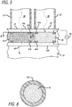
- the inert gas volumes 40 of the respective plasma switches 24 are not isolated from each other, as illustrated in Fig. 5 , the inert gas volumes 40 are preferably maintained at atmospheric pressure, and the distance between the electrodes 42 of each plasma switch 24 are preferably less than 0.2 of the distance between adjacent plasma switches 24, thereby minimizing the possibility that the energized electrodes 42 of one plasma switch 24 will ignite the inert gas volume 40 of an adjacent plasma switch 24 into a plasma field 48; that is, ignition of the inert gas volume 40 into the plasma field 48 will be localized to the plasma switch 24 that is energized.
- the inert gas volumes 40 of the respective plasma switches 24 are isolated from each other via the dielectric side walls 44c, as illustrated in Fig.
- the ignition of the inert gas volume 40 into the plasma field 48 will naturally be localized to the plasma switch 24 that is energized, the distance between the electrodes 42 of each plasma switch 24 may be greater than 0.2 of the distance between adjacent plasma switches 24. Furthermore, the inert gas volumes 40 may be maintained at a pressure substantially less than atmospheric pressure (e.g., 0.1 to 10 Torr cm), thereby enhancing ignition of the inert gas volume 40 into the respective plasma field 48 in response to the supply of the voltage potential to the respective electrodes 42.
- atmospheric pressure e.g., 0.1 to 10 Torr cm
- the switch times for the plasma switch 24 are on the order of microseconds to seconds, based on the time required to activate the plasma field 48.
- the plasma field 48 may be activated in the time it takes to establish a standing wave for the frequency generated by the power supply 28.
- Typical ionization rate constants for ionization are on the order of 10 -12 s (10 12 Hz) with relaxation times of 10 -8 s (10 8 Hz) or faster.
- the operating frequency of the power supply 28 is less than the relaxation time of the plasma field 48 to conserve power.
- the plasma field 48 have an effective permittivity ⁇ n , such that the desired blocking or attenuation characteristics of the plasma field 48 with respect to the RF signal propagating within the respective antenna feed element 22 are achieved.
- ⁇ n an effective permittivity
- Region 1 can be considered the media within the antenna feed element 22 (e.g., air)
- region 2 can be considered the plasma field 48 within the plasma switch 24.
- some of the energy from the incident wave must be reflected off the interface, as illustrated in Fig. 5 .
- T ⁇ 2 n ⁇ 2 n ⁇ 1 + n ⁇ 2
- the plasma field 48 must provide a reflection coefficient at the interface of 1 for total blocking of the RF signal, and a reflection coefficient greater than 0, but less than 1, for attenuation of the RF signal.
- the effective permittivity ⁇ n of plasma is controlled by the collision frequency ⁇ , plasma frequency ⁇ pe , and electron number density n e .
- the plasma is "underdense" when the plasma density n e ⁇ n ec , and "overdense” when n e > n ec .
- An overdense medium has a reflective constant of unity, so that the RF signal is completely blocked, and none of the RF signal is transmitted through the plasma field 48.
- An underdense medium can still provide attenuation to an RF signal (the attenuation increasing with the density of the plasma) by reflecting a portion of the incident RF signal.
- the RF signal will be blocked by the plasma switch 24, and if the frequency of the RF signal is greater than the resonant frequency of the plasma field 48, the RF signal will pass through the plasma switch 24.
- the plasma density of the plasma field 48 will generally dictate the blocking or attenuating characteristics of the plasma switch 24 with respect to the RF energy propagating through the respective antenna feed element 22. For example, for RF energy having a frequency of several GHz, as a general rule, a plasma field 48 having a plasma density greater than 10 9 free electrons per cm 3 will completely block RF energy incident on the plasma field 48, whereas a plasma field 48 having a plasma density in the range of 10 7 -10 9 free electrons per cm 3 will attenuate, at varying degrees, RF energy incident on the plasma field 48.
- RF energy is blocked if less than ten percent of the RF energy passes through the plasma switch 24; however, it is preferred that less than one percent of the RF energy passes through the plasma switch 24 when the RF energy is blocked.
- the voltage applied to the electrodes 42 by the power supply 28 and the distance between the electrodes 42 can be selected to provide the desired blocking or attenuation (at various attenuation levels) of the RF energy of a given frequency through the plasma switch 24.
- the level of the voltage applied to the electrodes 42 by the power supply 28 to completely block the RF energy will generally be higher than the voltage applied to the electrodes 42 by the power supply 28 to attenuate the RF energy.
- several different voltage levels and corresponding attenuation levels may be stored in memory, such that the control circuitry 30, for any desired attenuation level for an antenna feed element 22, the control circuitry 30 may retrieve the corresponding voltage level from memory, and command the power supply 28 to deliver that that corresponding voltage level to the electrodes 42 of the plasma switch 24 corresponding to that antenna feed element 22.
- the antenna 10 is operated in the transmit mode or receive mode (step 102).
- a subset of the antenna feed elements 22 is selected (step 104).
- the subset of antenna feed elements 22 may be selected by the control circuitry 30.
- the subset of the antenna feed elements 22 may comprise, e.g., only a single antenna feed element, or may comprise multiple antenna feed elements.
- RF energy is conveyed between the spherical dielectric lens 20 and the RF combiner 26 in accordance with the transmit mode or the receive mode (step 106). That is, in the receive mode, the RF energy is received from the object of interest 38a at the spherical dielectric lens 20, and in the transmit mode, the RF energy is transmitted from the spherical dielectric lens 20 to an object of interest 38b.
- the plasma switches 24 can be independently operated to generate at least one RF beam 36 having a characteristic (e.g., a directional angle, an aperture, or a group size of the RF beam(s) 36).
- the subset of the antenna feed elements 22 is activated by not energizing the corresponding plasma switches 24, thereby passing the RF energy through the corresponding subset of the plasma switches 24 (step 108), and the remaining ones of the antenna feed elements are deactivated by energizing the corresponding plasma switches 24, thereby blocking the RF energy through the corresponding remaining ones of the plasma switches 24 (step 110).
- the control circuitry 30 may activate the subset of plasma switches 24 by commanding the power supply 28 to not apply voltage across each pair of electrodes 42 of the subset of plasma switches 24. As a result, an electric field is not applied across each inert gas volume 40 of the subset of the plasma switches 24, such that the inert gas volume 40 is not ignited into a plasma field 46, thereby passing the RF energy through the subset of plasma switches 24.
- the control circuitry 30 deactivates the remaining plasma switches 24 by commanding the power supply 28 to apply voltage across each pair of electrodes 42 of the remaining plasma switches 24. As a result, an electric field is applied across each inert gas volume 40 of the remaining plasma switches 24, such that the inert gas volume 40 is ignited into a plasma field 46, thereby blocking the RF energy through the remaining plasma switches 24.
- a different subset of the antenna feed elements 22 is selected (step 112), and the plasma switches 24 are independently operated again at steps 108 and 110 to modify the characteristic of the RF beam(s) 36. Steps 108 and 110 can be repeated to continually modify the characteristic of the RF beam(s) 36 as many times as desired.
- Another method 200 of operating the reconfigurable antenna 10 to geolocate an object of interest 38a will now be described with respect to Fig. 10 .
- the antenna 10 is operated in the receive mode (step 202).
- a subset of the antenna feed elements 22 is selected (step 204).
- the subset of antenna feed elements 22 can be selected by the control circuitry 30.
- the subset of the antenna feed elements 22 preferably includes only a single antenna feed element (e.g., if the object of interest 38a is to be located in a very small area of the sky), although in alternative embodiments, the subset of antenna feed elements 22 may comprise multiple antenna feed elements (e.g., if the object of interest 38a is to be located in large area of the sky). Then, RF energy is received from the object of interest 38a at the spherical dielectric lens 20 (step 206).
- the plasma switches 24 are independently operated to generate an RF beam 36a having a directional angle from the focusing element 20 is generated.
- the subset of the antenna feed elements is activated by not energizing the corresponding plasma switches 24, thereby passing the RF energy from the subset of antenna feed elements 22 to the RF combiner 26 (step 208), and the remaining ones of the antenna feed elements are deactivated by energizing the corresponding plasma switches 24, thereby blocking the RF energy from the antenna feed elements 22 to the RF combiner 26 (step 210).
- the control circuitry 30 preferably activates the subset of plasma switches 24 by commanding the power supply 28 to not apply voltage across each pair of electrodes 42 of the subset of plasma switches 24. As a result, an electric field is not applied across each inert gas volume 40 of the subset of the plasma switches 24, such that the inert gas volume 40 is not ignited into a plasma field 46, thereby passing the RF energy through the subset of plasma switches 24.
- the control circuitry 30 deactivates the remaining plasma switches 24 by commanding the power supply 28 to apply voltage across each pair of electrodes 42 of the remaining plasma switches 24. As a result, an electric field is applied across each inert gas volume 40 of the remaining plasma switches 24, such that the inert gas volume 40 is ignited into a plasma field 46, thereby blocking the RF energy through the remaining plasma switches 24.
- the signal strength of the RF energy output by the RF combiner 26 is measured, e.g., by the transceiver 12 (step 212). Then, it is determined whether or not all possible subsets of antenna feed elements 22 have been selected for activation (step 214). If not, different subsets of the antenna feed elements 22 are selected (step 216), and the plasma switches 24 are independently operated again at steps 208 and 210 to modify directional angle of the RF beam 36a and the RF energy output by the RF combiner 26 is measured at step 212.
- the object of interest 38a is geolocated based on the measured signal strength corresponding to at least one of the selected subsets of antenna feed elements 22, e.g., by the control circuitry 30.
- at least one subset of antenna feed elements 22 corresponding to at least one of the highest measured signal strengths is determined (step 218), the directional angle of the RF beam 36a is correlated to each of these subset(s) of antenna feed elements 22 (step 220), and the object of interest 38a is geolocated based on the correlated directional angle(s) of the RF beam 36a.
- Correlation can be accomplished, e.g., by storing in memory directional angles corresponding to the respective subsets of the antenna feed elements 22, and retrieving the directional angle corresponding to the subset(s) of antenna feed elements 22 corresponding to the highest measured signal strength(s).
- the directional angle of the RF beam 36a can be correlated to only this subset of antenna feed elements 22, and the object of interest 38a is geolocated by identifying the directional angle of the RF beam 36a as the location of the object of interest 38a.
- the directional angles of the RF beam 36a are correlated to the multiple subsets of antenna feed elements 22, and the object of interest 38a is geolocated by computing an interpolated directional angle from the directional angles of the RF beam 36a based on the corresponding highest measured signal strengths, and identifying the interpolated angle of the RF beam 36a as the location of the object of interest 38a.
- the directional angles can be weighted in accordance with the measured signal strengths corresponding to the multiple subsets of antenna feed elements 22, and then averaged to obtain the interpolated directional angle.
Landscapes
- Aerials With Secondary Devices (AREA)
- Variable-Direction Aerials And Aerial Arrays (AREA)
- Plasma Technology (AREA)
Abstract
Description
- The present disclosure generally relates to antennas, and more particularly, to reconfigurable antennas.
- Reconfigurable antennas are antennas that can dynamically modify their frequency band, radiation pattern, polarization, and/or gain properties in a controlled and reversible manner, and have applications in the fields of cellular radio communications, geolocation, radar (ground, airplane, and unmanned airborne vehicle), smart weapons, etc. Of particular interest to the present disclosure are reconfigurable antennas that can dynamically modify its radiation pattern, e.g., by steering a radiation beam or changing the width of the beam.
- Phased array antennas may be utilized to electronically steer a radiation beam through different angles, typically in the range of 60 degrees from the normal direction of the fixed physical array. Phased array antennas require that each element in the antenna array have an independent antenna element and radio frequency (RF) circuits that are aggregated to provide the overall antenna directivity, thereby creating an N-factor constraint that dictates a significant cost and power consumption penalty. Additionally, this N-factor constraint places significant circuit complexity on the antenna array, which limits production yield and operational reliability.
- A simpler approach employs a mechanically articulatable antenna that includes a mechanical platform that physically moves or tilts the antenna unit to steer a radiation beam through different angles, typically in a range as much as ±90 degrees. Due to its simple electrical design, which requires only one antenna element, the N-factor constraint typically imposed on phased array antennas is avoided. However, mechanically articulatable antennas are typically slow in articulation, require moving parts that are subject to degradation, are physically very large and heavy, and are relatively expensive, thereby limiting the application of this technology.
- Lens-based antenna approaches offer a viable and lower cost alternative to phased array and mechanically articulable antennas. For example, in one embodiment, multiple antenna feed elements can be placed around a spherical dielectric lens and selectively switched on and off to produce a wide field of beam coverage that avoids some of the engineering issues of phased array and mechanically articulatable antennas. However, although less technically complex than phased array antennas, reconfigurable lens-based antennas require multiple antenna feed elements and associated switches, and thus, still suffer from an N-factor constraint in terms of weight, power, size, and cost.
- Of particular interest to the present disclosure are the switches used to selectively turn the antenna feed elements on and off. Various types of conventional switches that can be used for the antenna feed elements include servo-mechanical switches, ferrite switches, and pin-diode switches. Servo-mechanical switches are relatively slow, typically having switch speeds on the order of 10-3 seconds (or several kilohertz). Ferrite switches require a relatively large amount of power to operate. Pin-diode switches are relatively complicated and expensive. All known conventional switches, including servo-mechanical switches, ferrite switches, and pin-diode switches, require some type of transition from the antenna feed element to a board or to a connector, thereby introducing insertion losses and additional design complexity into the reconfigurable antenna design.
- There, thus remains a need for an improved mechanism for selectively switching antenna feed elements in a reconfigurable antenna.
- The present invention refers to a reconfigurable antenna comprising a plurality of antenna feed elements (e.g., a plurality of waveguides). The antenna feed elements can be circular, although the antenna feed elements may alternatively be rectangular. The reconfigurable antenna further may comprise a focusing element (e.g., a dielectric lens, such as a spherical dielectric lens) having a focal plane on which the antenna feed elements are located.
- The reconfigurable antenna may further comprise a plurality of plasma switches respectively associated with the antenna feed elements. The reconfigurable antenna may further comprise a radio frequency (RF) combiner coupled to the antenna feed elements via the respective plasma switches. Each of the plasma switches comprises a volume of inert gas (e.g., Neon, Xenon, Argon, or a combination thereof) and a pair of electrodes (e.g., ring electrodes) spanning the respective inert gas volume. In such case, the reconfigurable antenna may further comprise a dielectric chamber containing the inert gas volumes. This dielectric chamber may comprise side walls that isolate the respective inert gas volumes from each other, with such inert gas volumes being at a pressure less than atmospheric pressure. The dielectric chamber may comprise a top dielectric wall in which a first one of the pair of electrodes of each plasma switch is incorporated, and a bottom dielectric wall in which a second one of the pair of electrodes of each plasma switch is incorporated. The reconfigurable antenna may further comprise a power supply for supplying a voltage to the pair of electrodes of each of the plasma switches sufficient (e.g., 100V-300V DC/AC-RMS) to ignite the respective inert gas volume into a plasma field (e.g., having a plasma density greater than 109 free electrons per cm3).
- The reconfigurable antenna may further comprise control circuitry for independently operating the plasma switches to selectively activate and deactivate the antenna feed elements. To this end, the control circuitry may be for selectively controlling the supply of the voltage from the power supply to the respective plasma switches to selectively turn the respective antenna feed elements on or off. The control circuitry may be for independently operating the plasma switches to attenuate the antenna feed elements. The control circuitry may be for independently operating the plasma switches to dynamically steer an RF beam. For example, the control circuitry may be for independently operating the plasma switches to selectively activate and then deactivate the respective antenna feed elements one at a time. The control circuitry may be for independently operating the plasma switches to alternately activate and then deactivate two halves of the antenna feed elements. The control circuitry can be for independently operating the plasma switches to dynamically modify an aperture of a beam. The control circuitry can be for independently operating the plasma switches to activate and then deactivate different group sizes of antenna feed elements.
- The antenna can comprise at least one feed element (e.g., at least one waveguide). , The antenna feed element(s) can be circular, although the antenna feed element(s) may alternatively be rectangular. The reconfigurable antenna can further comprise a focusing element (e.g., a dielectric lens, such as a spherical dielectric lens) having a focal plane on which the antenna feed elements(s) are located.
- The antenna may further comprise at least one plasma switch respectively associated with the antenna feed element(s). If there are multiple antenna feed elements, the reconfigurable antenna may further comprise a radio frequency (RF) combiner coupled to the antenna feed elements via the respective plasma switches. Each of the plasma switch(es) comprises a volume of inert gas (e.g., Neon, Xenon, Argon, or a combination thereof), and a pair of electrodes spanning the respective volume of inert gas. In such case, the reconfigurable antenna may further comprise a dielectric chamber containing the inert gas volume(s). In the case of multiple plasma switches, this dielectric chamber may comprise side walls that isolate the respective inert gas volumes from each other, with such inert gas volumes being at a pressure less than atmospheric pressure. The dielectric chamber may comprise a top dielectric wall in which a first one of the pair of electrodes of each plasma switch is incorporated, and a bottom dielectric wall in which a second one of the pair of electrodes of each plasma switch is incorporated.
- The antenna further comprises a power supply is for supplying a voltage to the pair of electrodes of each of the plasma switch(es) sufficient to ignite the respective inert gas volume into a plasma field. In one embodiment, the plasma field is capable of deactivating the respective antenna feed element (e.g., if the plasma density is greater than 109 free electrons per cm3). In another embodiment, the plasma field is capable of attenuating the respective antenna feed element (e.g., if the plasma density is between 107-109 free electrons per cm3).
- The antenna may comprise at least one feed element (e.g., at least one waveguide). The antenna feed element(s) can be circular, although the antenna feed element(s) may alternatively be rectangular. The reconfigurable antenna may further comprise a focusing element (e.g., a dielectric lens, such as a spherical dielectric lens) having a focal plane on which the antenna feed elements(s) are located.
- The antenna may further comprise at least one plasma switch respectively associated with the antenna feed element(s), and control circuitry for operating each of the plasma switch(es) to attenuate each of the antenna feed element(s). If there are multiple antenna feed elements, the reconfigurable antenna may further comprise a radio frequency (RF) combiner coupled to the antenna feed elements via the respective plasma switches. Each of the plasma switch(es) comprises a volume of inert gas (e.g., Neon, Xenon, Argon, or a combination thereof), and a pair of electrodes spanning the respective volume of inert gas. In such case, the reconfigurable antenna may further comprise a dielectric chamber containing the inert gas volume(s).
- In the case of multiple plasma switches, this dielectric chamber may comprise side walls that isolate the respective inert gas volumes from each other, with such inert gas volumes being at a pressure less than atmospheric pressure. The dielectric chamber may comprise a top dielectric wall in which a first one of the pair of electrodes of each plasma switch is incorporated, and a bottom dielectric wall in which a second one of the pair of electrodes of each plasma switch is incorporated. The antenna may further comprise a power supply for supplying a voltage to the pair of electrodes of each of the plasma switches sufficient to ignite the respective inert gas volume into a plasma field (e.g., having a plasma density between 107-109 free electrons per cm3).
- The invention also relates to a radio frequency (RF) system comprising the the antenna described above, and transmit and/or receive componentry coupled to the antenna feed element(s) via the respective plasma switch(es).
- The invention also relates to a method of operating an antenna comprising a focusing element and preferably having a focal plane, a plurality of antenna feed elements (e.g., waveguides) located on the focal plane, a plurality of plasma switches respectively associated with the antenna feed elements, and a radio frequency (RF) combiner coupled to the antenna feed elements via the plasma switches, is provided.
- The antenna feed elements can be circular, although the antenna feed elements may alternatively be rectangular. The antenna further may comprise a focusing element (e.g., a dielectric lens, such as a spherical dielectric lens) having a focal plane on which the antenna feed elements are located.
- The method preferably comprises (a) conveying RF energy between the focusing element and the RF combiner, (b) selecting a subset of the antenna feed elements (which may be a single antenna feed element), (c) independently operating the plasma switches to activate the subset of the antenna feed elements, thereby passing the RF energy through the corresponding subset of the plasma switches, and to deactivate remaining ones of the antenna feed elements, thereby blocking the RF energy through the corresponding remaining ones of the plasma switches, such that the antenna generates at least one RF beam having a characteristic, (d) selecting a different subset of the antenna feed elements, and (e) repeating step (c) with the different subset of antenna feed elements, such that the characteristic of the RF beam(s) is modified. As one example, the modified characteristic may be a directional angle of the RF beam(s). As another example, the modified characteristic may be an aperture of the RF beam(s). In still another example, the modified characteristic is a group size of the RF beam(s).
- Each plasma switch may comprise a volume of inert gas (e.g., Neon, Xenon, Argon, or a combination thereof), in which case, operating the plasma switches to activate the subset of the antenna feed elements may comprise not applying an electric field across each inert gas volume of the subset of plasma switches, thereby passing the RF energy through the subset of plasma switches, and applying an electric field across each inert gas volume of the remaining ones of the plasma switches to ignite the each inert gas volume into a respective plasma field (e.g., one having a plasma density greater than 109 free electrons per cm3), thereby blocking the RF energy through the remaining ones of the plasma switches.
- The invention also relates to a method of geolocating an object of interest using an antenna, preferably the antenna referred to above, the antenna preferably comprising a focusing element having a focal plane, a plurality of antenna feed elements located on the focal plane, a plurality of plasma switches respectively associated with the antenna feed elements, and a radio frequency (RF) combiner coupled to the antenna feed elements via the plasma switches, is provided. The antenna feed elements can be circular, although the antenna feed elements may alternatively be rectangular. The antenna may further comprise a focusing element (e.g., a dielectric lens, such as a spherical dielectric lens) having a focal plane on which the antenna feed elements are located.
- The method preferably comprises (a) receiving RF energy from the object of interest at the focusing element, (b) selecting a subset of the antenna feed elements (which may be a single antenna feed element), (c) independently operating the plasma switches to activate the subset of the antenna feed elements, thereby passing the RF energy from the subset of antenna feed elements to the RF combiner, and to deactivate remaining ones of the antenna feed elements, thereby blocking the RF energy from the remaining antenna feed elements to the RF combiner, such that an RF beam having a directional angle from the focusing element is generated, (d) measuring a signal strength of the RF energy output by the RF combiner, (e) selecting a different subset of the antenna feed elements, (f) repeating steps (c)-(d) for the different subset of antenna feed elements, and (g) geolocating the object of interest based on the measured signal strength corresponding to at least one of the selected subsets of antenna feed elements. Steps (e) and (f) may be repeated until all possible subsets of antenna feed elements have been selected and activated.
- Geolocating the object of interest preferably comprises determining at least one subset of antenna feed elements corresponding to at least one of the highest measured signal strengths, correlating the directional angle of the RF beam to each of the subset(s) of antenna feed elements, and geolocating the object of interest based on the correlated directional angle(s) of the RF beam. If only one subset of antenna feed elements corresponding to the highest measured signal strength is determined, the directional angle of the RF beam may be correlated to the only one subset of antenna feed elements, and the object of interest may be geolocated by identifying the directional angle of the RF beam as the location of the object of interest. If multiple subsets of antenna feed elements corresponding to the highest measured signal strengths are determined, the directional angles of the RF beam may be correlated to the multiple subsets of antenna feed elements, and the object of interest may be geolocated by computing an interpolated directional angle from the directional angles of the RF beam based on the corresponding highest measured signal strengths, and identifying the interpolated angle of the RF beam as the location of the object of interest.
- Each plasma switch may comprise a volume of inert gas (e.g., Neon, Xenon, Argon, or a combination thereof), in which case, operating the plasma switches to activate the subset of the antenna feed elements may comprise not applying an electric field across each inert gas volume of the subset of plasma switches, thereby passing the RF energy through the subset of plasma switches, and applying an electric field across each inert gas volume of the remaining ones of the plasma switches to ignite the each inert gas volume into a respective plasma field (e.g., one having a plasma density greater than 109 free electrons per cm3), thereby blocking the RF energy through the remaining ones of the plasma switches.
- Other and further aspects and features of the disclosure will be evident from reading the following detailed description of the presented embodiments, which are intended to illustrate, not limit, the disclosure.
- The drawings illustrate the design and utility of the present invention in which similar elements are referred to by common reference numerals. In order to better appreciate how the above-recited and other advantages and objects of the present invention are obtained, a more particular description of the present invention briefly described above will be rendered by reference to the accompanying drawings in which:
-
Fig. 1 is a block diagram of a radio frequency (RF) system; -
Fig. 2 is a plan view of a reconfigurable antenna used in the RF system ofFig. 1 ; -
Fig. 3 is a plan view of a spherical dielectric lens used in the reconfigurable antenna ofFig. 2 ; -
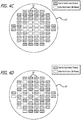
Fig. 4a is a plan view of an array of antenna feed elements used in the reconfigurable antenna ofFig. 2 , particularly showing one configuration of activated antenna feed elements; -
Fig. 4b is a plan view of an array of antenna feed elements used in the reconfigurable antenna ofFig. 2 , particularly showing another configuration of activated antenna feed elements; -
Fig. 4c is a plan view of an array of antenna feed elements used in the reconfigurable antenna ofFig. 2 , particularly showing still another configuration of activated antenna feed elements; -
Fig. 4d is a plan view of an array of antenna feed elements used in the reconfigurable antenna ofFig. 2 , particularly showing yet another configuration of activated antenna feed elements; -
Fig. 5 is a cross-sectional view of one embodiment of plasma switches used in the reconfigurable antenna ofFig. 2 ; -
Fig. 6 is a cross-sectional view of a plasma switch ofFig. 5 , taken along the line 6-6; -
Fig. 7 is a cross-sectional view of another embodiment of plasma switches used in the reconfigurable antenna ofFig. 2 ; -
Fig. 8 is a plan view of an electromagnetic wave transmitted through and reflected from an interface between two media; -
Fig. 9 is a flow diagram illustrating one method of operating the reconfigurable antenna ofFig. 2 to dynamically generate RF beams with differing characteristics; and -
Fig. 10 is a flow diagram illustrating one method of operating the reconfigurable antenna ofFig. 2 to geolocate an object of interest. - Referring to
Figs. 1-3 , areconfigurable antenna 10 will now be described. In a conventional manner, thereconfigurable antenna 10 is coupled to transmit and/or receive componentry in the form of atransceiver 12 that transmits and/or receives RF signals to and from thereconfigurable antenna 10 via awaveguide 14. Thereconfigurable antenna 10,transceiver 12, andwaveguide 14 form at least a portion of an RF system, such as an RF communications system or geolocation system. Thereconfigurable antenna 10 can be mounted to the structural body of a communications platform, such as a building (e.g., a tracking station) or spacecraft (e.g., a communications satellite). - The
reconfigurable antenna 10 comprises anRF focusing element 20, which can take the form of a dielectric lens, and in particular, a spherical dielectric lens. TheRF focusing element 20 can also take the form of flat lens, e.g., a bi-convex, a plano-convex lens, or a gradient-index (GRIN) lens. The sphericaldielectric lens 20 is composed of a dielectric material having a suitable dielectric constant and loss tangent, such as polytetrafluoroethylene or polycarbonate. As best shown inFig. 3 , the sphericaldielectric lens 20 exhibits the beneficial property of uniformity across itshemisphere 20a, so that RF plane waves 34 that are incident on thishemisphere 20a from respective particular directional arrival angles are predictably focused at correspondingpoints 31 along a sphericalfocal plane 32 adjacent theopposite hemisphere 20b of the sphericaldielectric lens 20, and conversely, a RF energy emitted frompoints 31 along thefocal plane 32 that are incident on theopposite hemisphere 20b predictably exits thehemisphere 20a as RF plane waves 34 at corresponding directional departure angles. As can be appreciated from the following discussion, the use of a sphericaldielectric lens 20, as opposed to a phased antenna array, allows the use of asingle waveguide 14 for routing RF signals between thereconfigurable antenna 10 and thetransceiver 12, thereby providing for a simpler antenna design, while still allowing beam steering or beam aperture modification. - The
reconfigurable antenna 10 further comprises an array of switchably selectableantenna feed elements 22, the apertures of which are located atselected points 31 around thefocal plane 32 of the sphericaldielectric lens 20. Eachantenna feed element 22 can take the form of a waveguide. Thefocal plane 32 may be coincident with the surface of the sphericaldielectric lens 20, such that theantenna feed elements 22 may be bonded directly to the surface of the sphericaldielectric lens 20, although in presented embodiments, thefocal plane 32 may be spatially offset from the surface of the sphericaldielectric lens 20, in which case, theantenna feed elements 22 may be likewise spatially offset from the surface of the sphericaldielectric lens 20, allowing the sphericaldielectric lens 20 to be moved relative to theantenna feed elements 22 to align the apertures of theantenna feed elements 22 with thefocal plane 32. - Thus, an
incoming RF beam 36a emitted from an object ofinterest 38a (in this case, a source of RF radiation) may be incident on the surface of the sphericaldielectric lens 20 and focused on one or more of theantenna feed elements 22. Conversely, RF energy emitted by one or more of theantenna feed elements 22 may be directed from the surface of the sphericaldielectric lens 20 as anoutgoing RF beam 36b to an object ofinterest 38b. When thereconfigurable antenna 10 is operated in a receive mode, theantenna feed elements 22 may be selectively and independently activated to allow thetransceiver 12 to receive RF energy emitted by the object ofinterest 38a, and when thereconfigurable antenna 10 is operated in a transmit mode, theantenna feed elements 22 may be selectively and independently activated to allow thetransceiver 12 to transmit RF energy to the object ofinterest 38b. - To this end, the
reconfigurable antenna 10 further comprises an array of plasma switches 24 respectively associated with theantenna feed elements 22, and anRF combiner 26 coupled to theantenna feed elements 22 that serves to convey RF energy between the multipleantenna feed elements 22 and thesingle waveguide 14 coupled to thetransceiver 12. The plasma switches 24 may be conveniently disposed between the respectiveantenna feed elements 22 and theRF combiner 26, although in alternative embodiments, the plasma switches 24 may be located anywhere in the path of theantenna feed elements 22. - The
reconfigurable antenna 10 can be designed to transmit and receive circularly polarized RF energy (e.g., both left hand circularly polarized (LHCP) and right hand circularly polarized (RHCP)), although in alternative embodiments, thereconfigurable antenna 10 may be designed to transmit and receive linearly polarized RF energy (e.g., both horizontally polarized (HP) and vertically polarized (VP)). The cross-sectional profile of theantenna feed elements 22, plasma switches 24,RF combiner 26, andwaveguide 14 can be circular, although in alternative embodiments, the cross-sectional profile may be rectangular. - As briefly discussed above, the
antenna feed elements 22 may be selectively activated via the plasma switches 24. To this end, thereconfigurable antenna 10 further comprises apower supply 28 for supplying power to the plasma switches 24, andcontrol circuitry 30 for independently operating the plasma switches 24 to selectively activate the respectiveantenna feed elements 22 by selectively controlling the supply of voltage from thepower supply 28 to the respective plasma switches 24, as will be described in further detail below. Rather than turning the antenna feed element(s) 22 on or off, thecontrol circuitry 30 may independently attenuate theantenna feed elements 22 by selectively controlling the supply of voltage form thepower supply 28 to the respective plasma switches 24. - The
control circuitry 30 may be for independently operating the plasma switches 24 via thepower supply 28 to dynamically steer the RF beam. InFig. 4a , thecontrol circuitry 30 may independently operate the plasma switches 24 to direct the RF beam towards a small portion of the sky by activating and then deactivating only oneantenna feed element 22 at a time. InFig. 4b , thecontrol circuitry 30 may independently operate the plasma switches 24 to direct the RF beam towards half of the sky by activating a first contiguous half of theantenna feed elements 22 while deactivating the second contiguous half of theantenna feed elements 22, and then activating the second contiguous half of theantenna feed elements 22 while deactivating the first contiguous half of theantenna feed elements 22. - The
control circuitry 30 may also be for independently operating the plasma switches 24 to dynamically modify an aperture of the RF beam. InFig. 4c , thecontrol circuitry 30 may independently operate the plasma switches 24 to modify the aperture of the RF beam by activating different sized ellipsoidal groups ofantenna feed elements 22. Thecontrol circuitry 30 may also be for independently operating the plasma switches 24 to dynamically generate different groupings of multiple RF beams 36. InFig. 4d , thecontrol circuitry 30 may independently operate the plasma switches 24 to generate fifteen RF beams by activating fifteen correspondingantenna elements 22. - It can be appreciated from the foregoing that the
reconfigurable antenna 10 may be utilized to geolocate the object of interest 38, and depending on the particular application, to communicate with such object of interest 38. For example, the specific direction of arrival of theincoming RF beam 36a, and thus, the angular location of the object of interest 38, may be ascertained by interrogating theantenna feed elements 22, and in particular, by activating and deactivating selected ones of theantenna feed elements 22, and determining the particular antenna feed element(s) 22 that receive RF energy from the object of interest 38. The antenna feed element(s) 22 that receive the RF energy from the object of interest 38 can then be selected to communicate (either in receive mode to receive RF energy or transmit mode to transmit RF energy) with the geolocated object of interest 38. - Referring now to
Figs. 5 and 6 , aplasma switch 24 will be described in further detail. Eachplasma switch 24 comprises a volume ofinert gas 40 disposed in a signal path between the aperture of the respectiveantenna feed element 22 and theRF combiner 26, a pair of electrodes 42 spanning theinert gas volume 40, and adielectric chamber 44 containing theinert gas volume 40. - The
inert gas volume 40 can be located between the end of theantenna feed element 22 and theRF combiner 26, although the volume ofinert gas 40 may be disposed in the middle of theantenna feed element 22 if desired. Theinert gas volume 40 may comprise, e.g., Neon, Xenon, or Argon, or a combination thereof to minimize corrosion of the electrodes 42, although theinert gas volume 40 may alternatively comprise air if the electrodes 42 are not exposed to theinert gas volume 40. - Both electrodes 42 can be ring electrodes that are disposed around the circumference of the inner cavity of the respective
antenna feed element 22 to minimize interference of RF signals propagating within theantenna feed element 22 when activated. Because the cross-section of theantenna feed element 22 may be circular, the ring electrode 42 can likewise be circular. However, in the case where the cross-section of theantenna feed element 22 can be rectangular, the ring electrode 42 may also be be rectangular. The electrodes 42 may take other forms that do not significantly interfere with the RF signal propagating through theantenna feed element 22 when activated. - The
dielectric chamber 44 can be composed of any suitable dielectric material (e.g., glass) that is essentially transparent to RF energy and that is capable of containing theinert gas volume 40. Thedielectric chamber 44 comprises atop wall 44a (or layer) in which thetop electrode 42a is incorporated, and abottom wall 44b (or layer) in which thebottom electrode 42b is incorporated. The electrodes 42 may be suitably patterned onto or within the respective top and bottomdielectric walls 44. Notably, thetop wall 44a andbottom wall 44b of thedielectric chamber 44 may span the entire array of plasma switches 24, such that a singletop wall 44a and asingle bottom wall 44b may be used to contain all of theinert gas volumes 40 in the array of plasma switches 24. As illustrated inFig. 7 , thedielectric chamber 44 may optionally comprise side walls 44c that isolate the respectiveinert gas volumes 40 for the plasma switches 24 from each other. - Each
plasma switch 24 is capable of transforming the respectiveinert gas volume 40 into plasma, which is an ionized gas consisting of positive ions and free electrons, and is one of the four fundamental states of matter. Like a gas, a plasma does not have a definite shape or volume. However, unlike a gas, a plasma is electrically conductive. A plasma can be created by heating a gas to a high temperature or by subjecting a gas to a strong electric field. - The
power supply 28 is electrically coupled between the electrodes 42 of eachrespective plasma switch 24 via insulated wires (not shown) incorporated into the respective top and bottomdielectric walls control circuitry 30, thepower supply 28 is capable of supplying a voltage potential between the electrodes 42 of eachrespective plasma switch 24 to ignite the respectiveinert gas volume 40 into aplasma field 48, and terminating the supply of the voltage potential between the electrodes 42 to extinguish theplasma field 48. Thus, theplasma switch 24 operates like a virtual "door" within the respectiveantenna feed element 22 in that the energizedplasma field 48 generates a virtual wall that blocks the RF energy through theplasma switch 24 between the respectiveantenna feed element 22 and the RF combiner 26 (thereby deactivating that antenna feed element 22), and the lack of the energizedplasma field 48 generates a window that allows the RF signal to seamlessly pass through theplasma switch 24 between the respectiveantenna feed element 22 and the RF combiner 26 (thereby activating that antenna feed element 22). Instead of completely blocking the RF signal propagating within theantenna feed element 22, theplasma field 48 may attenuate the RF energy propagating through theantenna feed element 22 to theRF combiner 26. - Notably, a plasma is defined by three parameters, which must meet three conditions. First, a plasma has a Debye length over which an imposed electric field can be neutralized, defined as


- The
power supply 28 can be anRF power supply 28 having a typical RF frequency, such as, e.g., 900MHz, 2.4GHz, and 13.56GHz, although thepower supply 28 can take the form of a typical 60Hz power supply used for standard Neon light bulbs, or can even be DC. The voltage potential supplied to the electrodes 42 by thepower supply 28 is preferably high enough, and the distance between the electrodes 42 is preferably close enough, such that theinert gas volume 40, at given chamber pressure, will be ignited into theplasma field 48 in accordance with the three conditions for generating theplasma field 46 set forth above. - If the
inert gas volumes 40 of the respective plasma switches 24 are not isolated from each other, as illustrated inFig. 5 , theinert gas volumes 40 are preferably maintained at atmospheric pressure, and the distance between the electrodes 42 of eachplasma switch 24 are preferably less than 0.2 of the distance between adjacent plasma switches 24, thereby minimizing the possibility that the energized electrodes 42 of oneplasma switch 24 will ignite theinert gas volume 40 of anadjacent plasma switch 24 into aplasma field 48; that is, ignition of theinert gas volume 40 into theplasma field 48 will be localized to theplasma switch 24 that is energized. However, if theinert gas volumes 40 of the respective plasma switches 24 are isolated from each other via the dielectric side walls 44c, as illustrated inFig. 7 , the ignition of theinert gas volume 40 into theplasma field 48 will naturally be localized to theplasma switch 24 that is energized, the distance between the electrodes 42 of eachplasma switch 24 may be greater than 0.2 of the distance between adjacent plasma switches 24. Furthermore, theinert gas volumes 40 may be maintained at a pressure substantially less than atmospheric pressure (e.g., 0.1 to 10 Torr cm), thereby enhancing ignition of theinert gas volume 40 into therespective plasma field 48 in response to the supply of the voltage potential to the respective electrodes 42. - The switch times for the
plasma switch 24 are on the order of microseconds to seconds, based on the time required to activate theplasma field 48. Theoretically, theplasma field 48 may be activated in the time it takes to establish a standing wave for the frequency generated by thepower supply 28. Typical ionization rate constants for ionization are on the order of 10-12s (1012 Hz) with relaxation times of 10-8s (108 Hz) or faster. Preferably, the operating frequency of thepower supply 28 is less than the relaxation time of theplasma field 48 to conserve power. - It is desirable that the
plasma field 48 have an effective permittivity εn , such that the desired blocking or attenuation characteristics of theplasma field 48 with respect to the RF signal propagating within the respectiveantenna feed element 22 are achieved. In particular, with reference toFig. 8 , consider a plane wave that is propagating along the positive z-axis with its electric field oriented in the x-direction. This plane wave is incident on an interface separating two media (Region 1 and Region 2), each with a unique permittivity ε, permeability µ, conductivity σ.Region 1 can be considered the media within the antenna feed element 22 (e.g., air), whereasregion 2 can be considered theplasma field 48 within theplasma switch 24. To satisfy the boundary condition betweenRegion 1 andRegion 2, some of the energy from the incident wave must be reflected off the interface, as illustrated inFig. 5 . - Two parameters that predict the amplitude of the transmitted and reflected waves can be developed. One parameter is known as the transmission coefficient


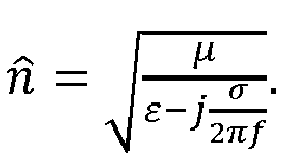
- Thus, it can be appreciated that the
plasma field 48 must provide a reflection coefficient at the interface of 1 for total blocking of the RF signal, and a reflection coefficient greater than 0, but less than 1, for attenuation of the RF signal. Associated with a plasma is an effective permittivity εn equal to:

plasma field 48. An underdense medium can still provide attenuation to an RF signal (the attenuation increasing with the density of the plasma) by reflecting a portion of the incident RF signal. As a general rule, if the frequency of the RF signal is less than the resonant frequency of theplasma field 48, the RF signal will be blocked by theplasma switch 24, and if the frequency of the RF signal is greater than the resonant frequency of theplasma field 48, the RF signal will pass through theplasma switch 24. - The plasma density of the
plasma field 48 will generally dictate the blocking or attenuating characteristics of theplasma switch 24 with respect to the RF energy propagating through the respectiveantenna feed element 22. For example, for RF energy having a frequency of several GHz, as a general rule, aplasma field 48 having a plasma density greater than 109 free electrons per cm3 will completely block RF energy incident on theplasma field 48, whereas aplasma field 48 having a plasma density in the range of 107-109 free electrons per cm3 will attenuate, at varying degrees, RF energy incident on theplasma field 48. - For the purposes of this specification, RF energy is blocked if less than ten percent of the RF energy passes through the
plasma switch 24; however, it is preferred that less than one percent of the RF energy passes through theplasma switch 24 when the RF energy is blocked. The voltage applied to the electrodes 42 by thepower supply 28 and the distance between the electrodes 42 can be selected to provide the desired blocking or attenuation (at various attenuation levels) of the RF energy of a given frequency through theplasma switch 24. The level of the voltage applied to the electrodes 42 by thepower supply 28 to completely block the RF energy will generally be higher than the voltage applied to the electrodes 42 by thepower supply 28 to attenuate the RF energy. By the same token, the greater the level of voltage applied to the electrodes 42 by thepower supply 28, the greater the RF energy will be attenuated (if not otherwise completely blocked). For attenuation, several different voltage levels and corresponding attenuation levels may be stored in memory, such that thecontrol circuitry 30, for any desired attenuation level for anantenna feed element 22, thecontrol circuitry 30 may retrieve the corresponding voltage level from memory, and command thepower supply 28 to deliver that that corresponding voltage level to the electrodes 42 of theplasma switch 24 corresponding to thatantenna feed element 22. - Having described the arrangement, structure, and function of the
reconfigurable antenna 10, amethod 100 of operating thereconfigurable antenna 10 will now be described with respect toFig. 9 . First, theantenna 10 is operated in the transmit mode or receive mode (step 102). Next, a subset of theantenna feed elements 22 is selected (step 104). The subset ofantenna feed elements 22 may be selected by thecontrol circuitry 30. The subset of theantenna feed elements 22 may comprise, e.g., only a single antenna feed element, or may comprise multiple antenna feed elements. Then, RF energy is conveyed between the sphericaldielectric lens 20 and theRF combiner 26 in accordance with the transmit mode or the receive mode (step 106). That is, in the receive mode, the RF energy is received from the object ofinterest 38a at the sphericaldielectric lens 20, and in the transmit mode, the RF energy is transmitted from the sphericaldielectric lens 20 to an object ofinterest 38b. - Then, the plasma switches 24 can be independently operated to generate at least one RF beam 36 having a characteristic (e.g., a directional angle, an aperture, or a group size of the RF beam(s) 36). In particular, the subset of the
antenna feed elements 22 is activated by not energizing the corresponding plasma switches 24, thereby passing the RF energy through the corresponding subset of the plasma switches 24 (step 108), and the remaining ones of the antenna feed elements are deactivated by energizing the corresponding plasma switches 24, thereby blocking the RF energy through the corresponding remaining ones of the plasma switches 24 (step 110). - The
control circuitry 30 may activate the subset of plasma switches 24 by commanding thepower supply 28 to not apply voltage across each pair of electrodes 42 of the subset of plasma switches 24. As a result, an electric field is not applied across eachinert gas volume 40 of the subset of the plasma switches 24, such that theinert gas volume 40 is not ignited into aplasma field 46, thereby passing the RF energy through the subset of plasma switches 24. In contrast, thecontrol circuitry 30 deactivates the remaining plasma switches 24 by commanding thepower supply 28 to apply voltage across each pair of electrodes 42 of the remaining plasma switches 24. As a result, an electric field is applied across eachinert gas volume 40 of the remaining plasma switches 24, such that theinert gas volume 40 is ignited into aplasma field 46, thereby blocking the RF energy through the remaining plasma switches 24. - Next, a different subset of the
antenna feed elements 22 is selected (step 112), and the plasma switches 24 are independently operated again atsteps Steps method 200 of operating thereconfigurable antenna 10 to geolocate an object ofinterest 38a will now be described with respect toFig. 10 . First, theantenna 10 is operated in the receive mode (step 202). Next, a subset of theantenna feed elements 22 is selected (step 204). The subset ofantenna feed elements 22 can be selected by thecontrol circuitry 30. For detailed geolocation of the object ofinterest 38a, the subset of theantenna feed elements 22 preferably includes only a single antenna feed element (e.g., if the object ofinterest 38a is to be located in a very small area of the sky), although in alternative embodiments, the subset ofantenna feed elements 22 may comprise multiple antenna feed elements (e.g., if the object ofinterest 38a is to be located in large area of the sky). Then, RF energy is received from the object ofinterest 38a at the spherical dielectric lens 20 (step 206). - Then, the plasma switches 24 are independently operated to generate an
RF beam 36a having a directional angle from the focusingelement 20 is generated. In particular, the subset of the antenna feed elements is activated by not energizing the corresponding plasma switches 24, thereby passing the RF energy from the subset ofantenna feed elements 22 to the RF combiner 26 (step 208), and the remaining ones of the antenna feed elements are deactivated by energizing the corresponding plasma switches 24, thereby blocking the RF energy from theantenna feed elements 22 to the RF combiner 26 (step 210). - The
control circuitry 30 preferably activates the subset of plasma switches 24 by commanding thepower supply 28 to not apply voltage across each pair of electrodes 42 of the subset of plasma switches 24. As a result, an electric field is not applied across eachinert gas volume 40 of the subset of the plasma switches 24, such that theinert gas volume 40 is not ignited into aplasma field 46, thereby passing the RF energy through the subset of plasma switches 24. In contrast, thecontrol circuitry 30 deactivates the remaining plasma switches 24 by commanding thepower supply 28 to apply voltage across each pair of electrodes 42 of the remaining plasma switches 24. As a result, an electric field is applied across eachinert gas volume 40 of the remaining plasma switches 24, such that theinert gas volume 40 is ignited into aplasma field 46, thereby blocking the RF energy through the remaining plasma switches 24. - Next, the signal strength of the RF energy output by the
RF combiner 26 is measured, e.g., by the transceiver 12 (step 212). Then, it is determined whether or not all possible subsets ofantenna feed elements 22 have been selected for activation (step 214). If not, different subsets of theantenna feed elements 22 are selected (step 216), and the plasma switches 24 are independently operated again atsteps RF beam 36a and the RF energy output by theRF combiner 26 is measured atstep 212. - If all the possible subsets of
antenna feed elements 22 have been determined to be selected for activation atstep 214, the object ofinterest 38a is geolocated based on the measured signal strength corresponding to at least one of the selected subsets ofantenna feed elements 22, e.g., by thecontrol circuitry 30. In particular, at least one subset ofantenna feed elements 22 corresponding to at least one of the highest measured signal strengths is determined (step 218), the directional angle of theRF beam 36a is correlated to each of these subset(s) of antenna feed elements 22 (step 220), and the object ofinterest 38a is geolocated based on the correlated directional angle(s) of theRF beam 36a. Correlation can be accomplished, e.g., by storing in memory directional angles corresponding to the respective subsets of theantenna feed elements 22, and retrieving the directional angle corresponding to the subset(s) ofantenna feed elements 22 corresponding to the highest measured signal strength(s). - Only one subset of
antenna feed elements 22 corresponding to the highest measured signal strength may be determined, in which case, the directional angle of theRF beam 36a can be correlated to only this subset ofantenna feed elements 22, and the object ofinterest 38a is geolocated by identifying the directional angle of theRF beam 36a as the location of the object ofinterest 38a. Multiple subsets ofantenna feed elements 22 corresponding to the highest measured signal strengths can also be determined, in which case, the directional angles of theRF beam 36a are correlated to the multiple subsets ofantenna feed elements 22, and the object ofinterest 38a is geolocated by computing an interpolated directional angle from the directional angles of theRF beam 36a based on the corresponding highest measured signal strengths, and identifying the interpolated angle of theRF beam 36a as the location of the object ofinterest 38a. For example, the directional angles can be weighted in accordance with the measured signal strengths corresponding to the multiple subsets ofantenna feed elements 22, and then averaged to obtain the interpolated directional angle. - Further, the disclosure comprises embodiments according to the following clauses:
- 1. A reconfigurable antenna, comprising:
- a plurality of antenna feed elements;
- a plurality of plasma switches respectively associated with the antenna feed elements; and
- control circuitry for independently operating the plasma switches to selectively activate and deactivate the antenna feed elements.
- 2. The reconfigurable antenna of
clause 1, further comprising a focusing element having a focal plane on which the antenna feed elements are located. - 3. The reconfigurable antenna of
clause 2, wherein the focusing element is a dielectric lens. - 4. The reconfigurable antenna of clause 3, wherein the dielectric lens is a spherical dielectric lens.
- 5. The reconfigurable antenna of any of the preceding clauses, wherein each of the antenna feed elements comprises a waveguide.
- 6. The reconfigurable antenna of any of the preceding clauses, wherein the control circuitry is for independently operating the plasma switches to attenuate the antenna feed elements.
- 7. The reconfigurable antenna of any of the preceding clauses, further comprising a radio frequency (RF) combiner coupled to the antenna feed elements via the respective plasma switches.
- 8. The reconfigurable antenna of any of the preceding clauses, wherein each of the plasma switches comprises:
- a volume of inert gas; and
- a pair of electrodes spanning the respective inert gas volume.
- 9. The reconfigurable antenna of clause 8, wherein at least one of the electrodes is a ring electrode.
- 10. The reconfigurable antenna of clauses 8 or 9, further comprising a dielectric chamber containing the inert gas volumes.
- 11. The reconfigurable antenna of
clause 10, wherein the dielectric chamber comprises side walls that isolate the respective inert gas volumes from each other. - 12. The reconfigurable antenna of any of the
clauses 10 or 11, wherein the dielectric chamber contains the inert gas volumes at a pressure less than atmospheric pressure. - 13. The reconfigurable antenna of any of the clauses 10-12, wherein the dielectric chamber comprises a top dielectric wall in which a first one of the pair of electrodes of each plasma switch is incorporated, and a bottom dielectric wall in which a second one of the pair of electrodes of each plasma switch is incorporated.
- 14. The reconfigurable antenna of any of the clauses 8-13, wherein the inert gas is Neon, Xenon, Argon, or a combination thereof.
- 15. The reconfigurable antenna of any of the clauses 8-14, further comprising a power supply for supplying a voltage to the pair of electrodes of each of the plasma switches sufficient to ignite the respective inert gas volume into a plasma field.
- 16. The reconfigurable antenna of clause 15, wherein the plasma field has a plasma density greater than 109 free electrons per cm3.
- 17. The reconfigurable antenna of clause 15 or 16, wherein the control circuitry is for selectively controlling the supply of the voltage from the power supply to the respective plasma switches to selectively turn the respective antenna feed elements on or off.
- 18. The reconfigurable antenna of any of the preceding clauses, wherein the control circuitry is for independently operating the plasma switches to dynamically steer an RF beam.
- 19. The reconfigurable antenna of clause 18, wherein the control circuitry is for independently operating the plasma switches to selectively activate and then deactivate the respective antenna feed elements one at a time.
- 20. The reconfigurable antenna of clause 18 or 19, wherein the control circuitry is for independently operating the plasma switches to alternately activate and then deactivate two halves of the antenna feed elements.
- 21. The reconfigurable antenna of any of the preceding clauses, wherein the control circuitry is for independently operating the plasma switches to dynamically modify an aperture of a beam.
- 22. The reconfigurable antenna of any of the preceding clauses, wherein the control circuitry is for independently operating the plasma switches to activate and then deactivate different group sizes of antenna feed elements.
- 23. The reconfigurable antenna of any of the preceding clauses wherein each of the antenna feed elements is circular.
- 24. A radio frequency (RF) system, comprising:
- the reconfigurable antenna of any of the preceding clauses and
- transmit and/or receive componentry coupled to the antenna feed elements via the respective plasma switches.
- 25. An antenna, comprising:
- at least one antenna feed element;
- at least one plasma switch respectively associated with the at least one antenna feed element, wherein each of the at least one plasma switch comprises a volume of inert gas, and a pair of electrodes spanning the respective volume of inert gas; and
- a power supply for supplying a voltage to the pair of electrodes of each of the at least one plasma switch sufficient to ignite the respective inert gas volume into a plasma field.
- 26. The antenna of clause 25, further comprising a focusing element having a focal plane on which the antenna feed element is located.
- 27. The antenna of
clause 26, wherein the focusing element is a dielectric lens. - 28. The antenna of clause 27, wherein the dielectric lens is a spherical dielectric lens.
- 29. The antenna of any of the clauses 25-28, wherein each of the at least one antenna feed element comprises a waveguide with which the respective plasma switch is associated.
- 30. The antenna of any of the clauses 25-29, wherein the plasma field is capable of deactivating the respective antenna feed element.
- 31. The antenna of any of the clauses 25-30, wherein the plasma field is capable of attenuating the respective antenna feed element.
- 32. The antenna of any of the clauses 25-31, wherein at least one of the electrodes is a ring electrode.
- 33. The antenna of any of the clauses 25-32, wherein the at least one antenna feed element comprises a plurality of antenna feed elements, and the at least one plasma switch comprises a plurality of plasma switches.
- 34. The antenna of any of the clauses 25-33, further comprising a radio frequency (RF) combiner coupled to the antenna feed elements.
- 35. The antenna of any of the clauses 25-34, further comprising a dielectric chamber containing the inert gas volumes.
- 36. The antenna of clause 35, wherein the dielectric chamber comprises side walls that isolate the respective inert gas volumes from each other.
- 37. The antenna of clause 35 or 36, wherein the dielectric chamber contains the inert gas volumes at a pressure less than atmospheric pressure.
- 38. The antenna of any of the clauses 35-37, wherein the dielectric chamber comprises a top dielectric wall in which a first one of the pair of electrodes of each plasma switch is incorporated, and a bottom dielectric wall in which a second one of the pair of electrodes of each plasma switch is incorporated.
- 39. The antenna of any of the clauses 25-38, wherein the inert gas is Neon, Xenon, Argon, or a combination thereof.
- 40. The antenna of any of the clauses 25-39, wherein the plasma field has a plasma density greater than 109 free electrons per cm3.
- 41. The antenna of any of the clauses 25-40, wherein the plasma field has a plasma density between 107-109 free electrons per cm3.
- 42. The antenna of any of the clauses 25-41, wherein each of the at least one antenna feed element is circular.
- 43. A radio frequency (RF) system, comprising:
- the antenna of any of the clauses 25-42; and
- transmit and/or receive componentry coupled to the at least one antenna feed element via the at least one plasma switch.
- 44. An antenna, comprising:
- at least one antenna feed element;
- at least one plasma switch respectively associated with the at least one antenna feed element; and
- control circuitry for operating each of the at least one plasma switch to attenuate each of the at least one antenna feed element.
- 45. The antenna of
clause 44, further comprising a focusing element having a focal plane on which the at least one antenna feed element is located. - 46. The antenna of clause 45, wherein the focusing element is a dielectric lens.
- 47. The antenna of
clause 46, wherein the dielectric lens is a spherical dielectric lens. - 48. The antenna of any of the clauses 44-47, wherein each of the at least one antenna feed element comprises a waveguide.
- 49. The antenna of any of the clauses 44-48, wherein the at least one antenna feed element comprises a plurality of antenna feed element, and the at least one plasma switch comprises a plurality of plasma switches.
- 50. The antenna of clause 49, further comprising a radio frequency (RF) combiner coupled to the antenna feed elements via the respective plasma switches.
- 51. The antenna of any of the clauses 44-50, wherein each of the at least one plasma switch comprises:
- a volume of inert gas; and
- a pair of electrodes spanning the respective inert gas volume.
- 52. The antenna of clause 51, wherein at least one of the electrodes is a ring electrode.
- 53. The antenna of clause 51 or 52, further comprising a dielectric chamber containing the inert gas volume of the at least one plasma switch.
- 54. The antenna of clause 53, wherein the at least one antenna feed element comprises a plurality of antenna feed element, the at least one plasma switch comprises a plurality of plasma switches, and the dielectric chamber comprises side walls that isolate the respective inert gas volumes from each other.
- 55. The antenna of clause 53 or 54, wherein the dielectric chamber contains the inert gas volume of the at least one plasma switch at a pressure less than atmospheric pressure.
- 56. The antenna of any of the clauses 53-55, wherein the dielectric chamber comprises a top dielectric wall in which a first one of the pair of electrodes of each of the at least one plasma switch is incorporated, and a bottom dielectric wall in which a second one of the pair of electrodes of each of the at least one plasma switch is incorporated.
- 57. The antenna of any of the clauses 51-56, wherein the inert gas is Neon, Xenon, Argon, or a combination thereof.
- 58. The antenna of any of the clauses 51-57, further comprising a power supply for supplying a voltage to the pair of electrodes of each of the at least one plasma switch sufficient to ignite the respective inert gas volume into a plasma field.
- 59. The antenna of clause 58, wherein the plasma field has a plasma density between 107-109 free electrons per cm3.
- 60. The antenna of any of the preceding clauses 44-59, wherein each of the at least one antenna feed element is circular.
- 61. A radio frequency (RF) system, comprising:
- the antenna of any of the clauses 44-60; and
- transmit and/or receive componentry coupled to the antenna feed elements via the respective plasma switches.
- 62. A method of operating an antenna comprising a focusing element having a focal plane, a plurality of antenna feed elements located on the focal plane, a plurality of plasma switches respectively associated with the antenna feed elements, and a radio frequency (RF) combiner coupled to the antenna feed elements via the plasma switches, the method comprising:
- (a) conveying RF energy between the focusing element and the RF combiner;
- (b) selecting a subset of the antenna feed elements;
- (c) independently operating the plasma switches to activate the subset of the antenna feed elements, thereby passing the RF energy through the corresponding subset of the plasma switches, and to deactivate remaining ones of the antenna feed elements, thereby blocking the RF energy through the corresponding remaining ones of the plasma switches, such that the antenna generates at least one RF beam having a characteristic;
- (d) selecting a different subset of the antenna feed elements;
- (e) repeating step (c) with the different subset of antenna feed elements, such that the characteristic of the at least one RF beam is modified.
- 63. The method of clause 62, wherein the subset of the antenna feed elements comprises a single antenna feed element.
- 64. The method of clause 62 or 63, wherein the characteristic of the at least one RF beam is one or more of the following: a directional angle of the at least one RF beam;
an aperture of the at least one RF beam
a group size of the at least one RF beam; - 65. The method of any of the clauses 62-64, wherein the focusing element is a dielectric lens.
- 66. The method of clause 65, wherein the dielectric lens is a spherical dielectric lens.
- 67. The method of any of the clauses 62-66, wherein each of the antenna feed elements comprises a waveguide with which the respective plasma switch is associated.
- 68. The method of any of the clauses 62-67, wherein each plasma switch comprises a volume of inert gas, and wherein operating the plasma switches to activate the subset of the antenna feed elements comprises not applying an electric field across each inert gas volume of the subset of plasma switches, thereby passing the RF energy through the subset of plasma switches, and applying an electric field across each inert gas volume of the remaining ones of the plasma switches to ignite the each inert gas volume into a respective plasma field, thereby blocking the RF energy through the remaining ones of the plasma switches.
- 69. The method of clause 68, wherein the inert gas is Neon, Xenon, Argon, or a combination thereof.
- 70. The method of clause 68 or 69, wherein the respective plasma field has a plasma density greater than 109 free electrons per cm3.
- 71. A method of geolocating an object of interest using an antenna comprising a focusing element having a focal plane, a plurality of antenna feed elements located on the focal plane, a plurality of plasma switches respectively associated with the antenna feed elements, and a radio frequency (RF) combiner coupled to the antenna feed elements via the plasma switches, the method comprising:
- (a) receiving RF energy from the object of interest at the focusing element;
- (b) selecting a subset of the antenna feed elements;
- (c) independently operating the plasma switches to activate the subset of the antenna feed elements, thereby passing the RF energy from the subset of antenna feed elements to the RF combiner, and to deactivate remaining ones of the antenna feed elements, thereby blocking the RF energy from the remaining antenna feed elements to the RF combiner, such that an RF beam having a directional angle from the focusing element is generated;
- (d) measuring a signal strength of RF energy output by the RF combiner;
- (e) selecting a different subset of the antenna feed elements;
- (f) repeating steps (c)-(d) for the different subset of antenna feed elements; and
- (g) geolocating the object of interest based on the measured signal strength corresponding to at least one of the selected subsets of antenna feed elements.
- 72. The method of clause 71, wherein geolocating the object of interest comprises determining at least one subset of antenna feed elements corresponding to at least one of the highest measured signal strengths, correlating the directional angle of the RF beam to each of the at least one subset of antenna feed elements, and geolocating the object of interest based on the at least one correlated directional angle of the RF beam.
- 73. The method of clause 72, wherein only one subset of antenna feed elements corresponding to the highest measured signal strength is determined, the directional angle of the RF beam is correlated to the only one subset of antenna feed elements, and the object of interest is geolocated by identifying the directional angle of the RF beam as the location of the object of interest.
- 74. The method of clause 72, wherein multiple subsets of antenna feed elements corresponding to the highest measured signal strengths are determined, the directional angles of the RF beam are correlated to the multiple subsets of antenna feed elements, and the object of interest is geolocated by computing an interpolated directional angle from the directional angles of the RF beam based on the corresponding highest measured signal strengths, and identifying the interpolated angle of the RF beam as the location of the object of interest.
- 75. The method of any of the clauses 71-74, wherein steps (e) and (f) are repeated until all possible subsets of antenna feed elements have been selected and activated.
- 76. The method of any of the clauses 71-75, wherein the subset of the antenna feed elements comprises a single antenna feed element.
- 77. The method of any of the clauses 71-76, wherein the focusing element is a dielectric lens.
- 78. The method of clause 77, wherein the dielectric lens is a spherical dielectric lens.
- 79. The method of any of the clauses 71-78, wherein each of the antenna feed elements comprises a waveguide with which the respective plasma switch is associated.
- 80. The method of any of the clauses 71-79, wherein each plasma switch comprises a volume of inert gas, and wherein operating the plasma switches to activate the subset of the antenna feed elements comprises not applying an electric field across each inert gas volume of the subset of plasma switches, thereby passing the RF energy through the subset of plasma switches, and applying an electric field across each inert gas volume of the remaining ones of the plasma switches to ignite the each inert gas volume into a respective plasma field, thereby blocking the RF energy through the remaining ones of the plasma switches.
- 81. The method of clause 80, wherein the inert gas is Neon, Xenon, Argon, or a combination thereof.
- 82. The method of clause 80 or 81 wherein the respective plasma field has a plasma density greater than 109 free electrons per cm3.
- Although certain illustrative embodiments and methods have been disclosed herein, it can be apparent from the foregoing disclosure to those skilled in the art that variations and modifications of such embodiments and methods can be made without departing from the true spirit and scope of the art disclosed. Many other examples of the art disclosed exist, each differing from others in matters of detail only. Accordingly, it is intended that the art disclosed shall be limited only to the extent required by the appended claims and the rules and principles of applicable law.
Claims (15)
- A reconfigurable antenna, comprising:a plurality of antenna feed elements;a plurality of plasma switches respectively associated with the antenna feed elements; andcontrol circuitry for independently operating the plasma switches to selectively activate and deactivate the antenna feed elements.
- The reconfigurable antenna of claim 1, further comprising a focusing element having a focal plane on which the antenna feed elements are located, preferably
wherein the focusing element is a dielectric lens, more preferably
wherein the dielectric lens is a spherical dielectric lens. - The reconfigurable antenna of claims 1 or 2,wherein the control circuitry independently operates the plasma switches to attenuate the antenna feed elements.
- The reconfigurable antenna of any of the preceding claims, further comprising a radio frequency (RF) combiner coupled to the antenna feed elements via the respective plasma switches.
- The reconfigurable antenna of any of the preceding claims, wherein each of the plasma switches comprises:a volume of inert gas; anda pair of electrodes spanning the respective inert gas volume.
- The reconfigurable antenna of claim 5, further comprising a power supply for supplying a voltage to the pair of electrodes of each of the plasma switches sufficient to ignite the respective inert gas volume into a plasma field, preferably wherein the control circuitry selectively controls the supply of the voltage from the power supply to the respective plasma switches to selectively turn the respective antenna feed elements on or off.
- The reconfigurable antenna of any of the preceding claims, wherein the control circuitry independently operates the plasma switches to dynamically steer an RF beam, preferably wherein the control circuitry independently operates the plasma switches to selectively activate and then deactivate the respective antenna feed elements one at a time.
- A method of operating an antenna comprising a focusing element having a focal plane, a plurality of antenna feed elements located on the focal plane, a plurality of plasma switches respectively associated with the antenna feed elements, and a radio frequency (RF) combiner coupled to the antenna feed elements via the plasma switches, the method comprising:(a) conveying RF energy between the focusing element and the RF combiner;(b) selecting a subset of the antenna feed elements;(c) independently operating the plasma switches to activate the subset of the antenna feed elements, thereby passing the RF energy through the corresponding subset of the plasma switches, and to deactivate remaining ones of the antenna feed elements, thereby blocking the RF energy through the corresponding remaining ones of the plasma switches, such that the antenna generates at least one RF beam having a characteristic;(d) selecting a different subset of the antenna feed elements;(e) repeating step (c) with the different subset of antenna feed elements, such that the characteristic of the at least one RF beam is modified.
- The method of claim 8, wherein the characteristic of the at least one RF beam is one or more of the following:a directional angle of the at least one RF beam;an aperture of the at least one RF beam;a group size of the at least one RF beam.
- Use of a plasma switch in a reconfigurable antenna.
- A reconfigurable antenna comprising a plasma switch.
- Use of an antenna according to any of the preceding claims 1-7, 11, for geolocating an object of interest.
- A radio frequency system comprising an antenna according to any of the preceding claims 1-7, 11, and transmit and/or receive componentry coupled to the antenna feed elements via respective plasma swtiches.
- An aircraft comprising an antenna according to any of the preceding claims 1-7, 11.
- A method of geolocating an object of interest using an antenna according to any of the preceding claims 1-7, 11 comprising the steps of(a) receiving RF energy from the object of interest at the focusing element;(b) selecting a subset of the antenna feed elements;(c) independently operating the plasma switches to activate the subset of the antenna feed elements, thereby passing the RF energy from the subset of antenna feed elements to the RF combiner, and to deactivate remaining ones of the antenna feed elements, thereby blocking the RF energy from the remaining antenna feed elements to the RF combiner, such that an RF beam having a directional angle from the focusing element is generated;(d) measuring a signal strength of RF energy output by the RF combiner;(e) selecting a different subset of the antenna feed elements;(f) repeating steps (c)-(d) for the different subset of antenna feed elements; and(g) geolocating the object of interest based on the measured signal strength corresponding to at least one of the selected subsets of antenna feed elements.
Applications Claiming Priority (1)
| Application Number | Priority Date | Filing Date | Title |
|---|---|---|---|
| US15/490,750 US10230166B2 (en) | 2017-04-18 | 2017-04-18 | Plasma switched array antenna |
Publications (2)
| Publication Number | Publication Date |
|---|---|
| EP3392964A1 true EP3392964A1 (en) | 2018-10-24 |
| EP3392964B1 EP3392964B1 (en) | 2021-06-02 |
Family
ID=61188657
Family Applications (1)
| Application Number | Title | Priority Date | Filing Date |
|---|---|---|---|
| EP18155708.3A Active EP3392964B1 (en) | 2017-04-18 | 2018-02-08 | Plasma switched array antenna |
Country Status (6)
| Country | Link |
|---|---|
| US (1) | US10230166B2 (en) |
| EP (1) | EP3392964B1 (en) |
| JP (1) | JP7066428B2 (en) |
| KR (1) | KR102399040B1 (en) |
| CN (1) | CN108736174B (en) |
| TW (1) | TWI752164B (en) |
Cited By (1)
| Publication number | Priority date | Publication date | Assignee | Title |
|---|---|---|---|---|
| WO2021061447A1 (en) * | 2019-09-23 | 2021-04-01 | Amphenol Antenna Solutions, Inc. | High gain single lens repeater platform |
Families Citing this family (8)
| Publication number | Priority date | Publication date | Assignee | Title |
|---|---|---|---|---|
| US10553943B2 (en) * | 2015-09-22 | 2020-02-04 | Qualcomm Incorporated | Low-cost satellite user terminal antenna |
| WO2019060596A2 (en) * | 2017-09-20 | 2019-03-28 | Cohere Technologies, Inc. | Low cost electromagnetic feed network |
| US20200137713A1 (en) * | 2018-10-26 | 2020-04-30 | Rohde & Schwarz Gmbh & Co. Kg | Method and system for beam assisted positioning |
| KR20220037508A (en) * | 2019-07-30 | 2022-03-24 | 룬웨이브 인코퍼레이티드 | Refractive index distribution lens-based communication system |
| US12283758B2 (en) * | 2020-01-24 | 2025-04-22 | Gilat Satellite Networks Ltd. | System and methods for use with electronically steerable antennas for wireless communications |
| AU2022288706A1 (en) * | 2021-06-10 | 2024-01-04 | Viasat, Inc. | Thinned array fed reflector and beam peak adjustment method thereof |
| US11894612B2 (en) * | 2022-02-25 | 2024-02-06 | Qualcomm Incorporated | Antenna array having a curved configuration |
| CN116315664B (en) * | 2023-05-11 | 2023-07-25 | 微网优联科技(成都)有限公司 | Reconfigurable antenna |
Citations (3)
| Publication number | Priority date | Publication date | Assignee | Title |
|---|---|---|---|---|
| US20040041741A1 (en) * | 2000-06-28 | 2004-03-04 | David Hayes | Antenna |
| US20160111793A1 (en) * | 2014-10-20 | 2016-04-21 | Honeywell International Inc. | Multiple beam antenna systems with embedded active transmit and receive rf modules |
| US20160149287A1 (en) * | 2014-11-20 | 2016-05-26 | The Boeing Company | Plasma-integrated switching devices |
Family Cites Families (21)
| Publication number | Priority date | Publication date | Assignee | Title |
|---|---|---|---|---|
| US5748151A (en) * | 1980-12-17 | 1998-05-05 | Lockheed Martin Corporation | Low radar cross section (RCS) high gain lens antenna |
| JPH0738562A (en) * | 1993-06-25 | 1995-02-07 | Mitsubishi Electric Corp | Wireless LAN antenna system |
| KR970029291A (en) * | 1995-11-16 | 1997-06-26 | 이데이 노부유키 | Electro-optical display device and its driving method |
| JPH10163730A (en) * | 1996-11-27 | 1998-06-19 | Murata Mfg Co Ltd | Automatic tracking antenna and tracking method for the same |
| JP2001094330A (en) * | 1999-09-21 | 2001-04-06 | Toshiba Corp | Array antenna device |
| JP2004500779A (en) * | 2000-03-20 | 2004-01-08 | サーノフ コーポレイション | Reconfigurable antenna |
| US6801790B2 (en) * | 2001-01-17 | 2004-10-05 | Lucent Technologies Inc. | Structure for multiple antenna configurations |
| US7132655B2 (en) * | 2002-12-02 | 2006-11-07 | Raytheon Company | Passive millimeter wave sensor using high temperature superconducting leads |
| US7292191B2 (en) * | 2004-06-21 | 2007-11-06 | Theodore Anderson | Tunable plasma frequency devices |
| US7145512B2 (en) * | 2005-03-30 | 2006-12-05 | Lucent Technologies Inc. | Reconfigurable plasma antenna with interconnected gas enclosures |
| US7151499B2 (en) * | 2005-04-28 | 2006-12-19 | Aramais Avakian | Reconfigurable dielectric waveguide antenna |
| US7855696B2 (en) * | 2007-03-16 | 2010-12-21 | Rayspan Corporation | Metamaterial antenna arrays with radiation pattern shaping and beam switching |
| US7756471B2 (en) * | 2007-03-31 | 2010-07-13 | Intel Corporation | Systems and methods for multi-element antenna arrays with aperture control shutters |
| KR100880892B1 (en) * | 2007-04-11 | 2009-01-30 | 한국전자통신연구원 | Multi-mode antenna and method of controlling mode of the same antenna |
| WO2010033779A1 (en) * | 2008-09-19 | 2010-03-25 | Delphi Technologies, Inc. | A multi-beam, polarization diversity narrow-band cognitive antenna |
| KR101266698B1 (en) * | 2008-11-28 | 2013-05-28 | 히타치가세이가부시끼가이샤 | Multibeam antenna device |
| WO2012080375A2 (en) * | 2010-12-14 | 2012-06-21 | Fasmetrics Ltd | Antenna system to control rf radiation exposure |
| US9166290B2 (en) * | 2011-12-21 | 2015-10-20 | Sony Corporation | Dual-polarized optically controlled microwave antenna |
| US9059505B1 (en) * | 2013-12-31 | 2015-06-16 | Google Technology Holdings LLC | Systems and methods for a reconfigurable antenna using design elements on an electronic device housing |
| JP2016082517A (en) * | 2014-10-21 | 2016-05-16 | シャープ株式会社 | Wireless device |
| US10553943B2 (en) * | 2015-09-22 | 2020-02-04 | Qualcomm Incorporated | Low-cost satellite user terminal antenna |
-
2017
- 2017-04-18 US US15/490,750 patent/US10230166B2/en active Active
-
2018
- 2018-01-31 TW TW107103502A patent/TWI752164B/en active
- 2018-02-02 JP JP2018017160A patent/JP7066428B2/en active Active
- 2018-02-08 EP EP18155708.3A patent/EP3392964B1/en active Active
- 2018-03-27 KR KR1020180035382A patent/KR102399040B1/en active Active
- 2018-03-27 CN CN201810258261.1A patent/CN108736174B/en active Active
Patent Citations (3)
| Publication number | Priority date | Publication date | Assignee | Title |
|---|---|---|---|---|
| US20040041741A1 (en) * | 2000-06-28 | 2004-03-04 | David Hayes | Antenna |
| US20160111793A1 (en) * | 2014-10-20 | 2016-04-21 | Honeywell International Inc. | Multiple beam antenna systems with embedded active transmit and receive rf modules |
| US20160149287A1 (en) * | 2014-11-20 | 2016-05-26 | The Boeing Company | Plasma-integrated switching devices |
Cited By (1)
| Publication number | Priority date | Publication date | Assignee | Title |
|---|---|---|---|---|
| WO2021061447A1 (en) * | 2019-09-23 | 2021-04-01 | Amphenol Antenna Solutions, Inc. | High gain single lens repeater platform |
Also Published As
| Publication number | Publication date |
|---|---|
| KR102399040B1 (en) | 2022-05-16 |
| CN108736174B (en) | 2021-02-19 |
| US10230166B2 (en) | 2019-03-12 |
| TW201840251A (en) | 2018-11-01 |
| JP7066428B2 (en) | 2022-05-13 |
| JP2018182723A (en) | 2018-11-15 |
| EP3392964B1 (en) | 2021-06-02 |
| KR20180117038A (en) | 2018-10-26 |
| CN108736174A (en) | 2018-11-02 |
| TWI752164B (en) | 2022-01-11 |
| US20180301803A1 (en) | 2018-10-18 |
Similar Documents
| Publication | Publication Date | Title |
|---|---|---|
| EP3392964B1 (en) | Plasma switched array antenna | |
| KR102130312B1 (en) | A beam steering antenna with a metasurface | |
| Dadgarpour et al. | One-and two-dimensional beam-switching antenna for millimeter-wave MIMO applications | |
| Sievenpiper et al. | A tunable impedance surface performing as a reconfigurable beam steering reflector | |
| Dadgarpour et al. | Passive beam switching and dual-beam radiation slot antenna loaded with ENZ medium and excited through ridge gap waveguide at millimeter-waves | |
| US5963169A (en) | Multiple tube plasma antenna | |
| US6870517B1 (en) | Configurable arrays for steerable antennas and wireless network incorporating the steerable antennas | |
| US4989006A (en) | Microwave absorption system | |
| KR20160130975A (en) | Dynamic polarization and coupling control for a steerable cylindrically fed holographic antenna | |
| US8384602B2 (en) | Plasma devices for steering and focusing antenna beams | |
| Gao et al. | Beam steering performance of compressed Luneburg lens based on transformation optics | |
| Vilar et al. | Q-band millimeter-wave antennas: An enabling technology for multigigabit wireless backhaul | |
| Kavitha et al. | A wide-scan phased array antenna for a small active electronically scanned array: a review | |
| Li et al. | A gain enhancement and flexible control of beam numbers antenna based on frequency selective surfaces | |
| US3484784A (en) | Antenna array duplexing system | |
| Shavit et al. | Scattering analysis of high performance large sandwich radomes | |
| Kamoda et al. | Millimeter‐wave beam former using liquid crystal | |
| Anand | Applications of metamaterial in antenna engineering | |
| Sadeghikia et al. | An advanced beamforming mechanism based on programmable plasma prisms | |
| Goode et al. | 3D printed 18 GHz to 28 GHz horn antenna and gradient index of refraction lens | |
| Xue et al. | Patch-fed planar dielectric slab waveguide Luneburg lens | |
| Shaikh et al. | Cost-Effective Electromagnetic Lens-Assisted Microstrip Patch Antenna Design for Location-Based Services in 5G/6G Technology Radio Frequency Front End. | |
| Anderson et al. | New Smart Plasma Antenna with Radiation Patterns and VSWR Measurements | |
| Astapenia et al. | Problematic Issues of the Accelerating Lens Deployment | |
| Yin et al. | Multifunctional Adaptive Invisibility Cloak Based on 3-Bit Reconfigurable Metasurface |
Legal Events
| Date | Code | Title | Description |
|---|---|---|---|
| PUAI | Public reference made under article 153(3) epc to a published international application that has entered the european phase |
Free format text: ORIGINAL CODE: 0009012 |
|
| STAA | Information on the status of an ep patent application or granted ep patent |
Free format text: STATUS: REQUEST FOR EXAMINATION WAS MADE |
|
| 17P | Request for examination filed |
Effective date: 20180208 |
|
| AK | Designated contracting states |
Kind code of ref document: A1 Designated state(s): AL AT BE BG CH CY CZ DE DK EE ES FI FR GB GR HR HU IE IS IT LI LT LU LV MC MK MT NL NO PL PT RO RS SE SI SK SM TR |
|
| AX | Request for extension of the european patent |
Extension state: BA ME |
|
| GRAP | Despatch of communication of intention to grant a patent |
Free format text: ORIGINAL CODE: EPIDOSNIGR1 |
|
| STAA | Information on the status of an ep patent application or granted ep patent |
Free format text: STATUS: GRANT OF PATENT IS INTENDED |
|
| INTG | Intention to grant announced |
Effective date: 20201028 |
|
| GRAJ | Information related to disapproval of communication of intention to grant by the applicant or resumption of examination proceedings by the epo deleted |
Free format text: ORIGINAL CODE: EPIDOSDIGR1 |
|
| STAA | Information on the status of an ep patent application or granted ep patent |
Free format text: STATUS: REQUEST FOR EXAMINATION WAS MADE |
|
| GRAP | Despatch of communication of intention to grant a patent |
Free format text: ORIGINAL CODE: EPIDOSNIGR1 |
|
| STAA | Information on the status of an ep patent application or granted ep patent |
Free format text: STATUS: GRANT OF PATENT IS INTENDED |
|
| INTC | Intention to grant announced (deleted) | ||
| INTG | Intention to grant announced |
Effective date: 20210226 |
|
| GRAS | Grant fee paid |
Free format text: ORIGINAL CODE: EPIDOSNIGR3 |
|
| GRAA | (expected) grant |
Free format text: ORIGINAL CODE: 0009210 |
|
| STAA | Information on the status of an ep patent application or granted ep patent |
Free format text: STATUS: THE PATENT HAS BEEN GRANTED |
|
| REG | Reference to a national code |
Ref country code: CH Ref legal event code: EP |
|
| AK | Designated contracting states |
Kind code of ref document: B1 Designated state(s): AL AT BE BG CH CY CZ DE DK EE ES FI FR GB GR HR HU IE IS IT LI LT LU LV MC MK MT NL NO PL PT RO RS SE SI SK SM TR |
|
| REG | Reference to a national code |
Ref country code: GB Ref legal event code: FG4D |
|
| REG | Reference to a national code |
Ref country code: AT Ref legal event code: REF Ref document number: 1399299 Country of ref document: AT Kind code of ref document: T Effective date: 20210615 |
|
| REG | Reference to a national code |
Ref country code: IE Ref legal event code: FG4D |
|
| REG | Reference to a national code |
Ref country code: DE Ref legal event code: R096 Ref document number: 602018017861 Country of ref document: DE |
|
| REG | Reference to a national code |
Ref country code: LT Ref legal event code: MG9D |
|
| PG25 | Lapsed in a contracting state [announced via postgrant information from national office to epo] |
Ref country code: BG Free format text: LAPSE BECAUSE OF FAILURE TO SUBMIT A TRANSLATION OF THE DESCRIPTION OR TO PAY THE FEE WITHIN THE PRESCRIBED TIME-LIMIT Effective date: 20210902 Ref country code: HR Free format text: LAPSE BECAUSE OF FAILURE TO SUBMIT A TRANSLATION OF THE DESCRIPTION OR TO PAY THE FEE WITHIN THE PRESCRIBED TIME-LIMIT Effective date: 20210602 Ref country code: LT Free format text: LAPSE BECAUSE OF FAILURE TO SUBMIT A TRANSLATION OF THE DESCRIPTION OR TO PAY THE FEE WITHIN THE PRESCRIBED TIME-LIMIT Effective date: 20210602 Ref country code: FI Free format text: LAPSE BECAUSE OF FAILURE TO SUBMIT A TRANSLATION OF THE DESCRIPTION OR TO PAY THE FEE WITHIN THE PRESCRIBED TIME-LIMIT Effective date: 20210602 |
|
| REG | Reference to a national code |
Ref country code: NL Ref legal event code: MP Effective date: 20210602 |
|
| REG | Reference to a national code |
Ref country code: AT Ref legal event code: MK05 Ref document number: 1399299 Country of ref document: AT Kind code of ref document: T Effective date: 20210602 |
|
| PG25 | Lapsed in a contracting state [announced via postgrant information from national office to epo] |
Ref country code: SE Free format text: LAPSE BECAUSE OF FAILURE TO SUBMIT A TRANSLATION OF THE DESCRIPTION OR TO PAY THE FEE WITHIN THE PRESCRIBED TIME-LIMIT Effective date: 20210602 Ref country code: RS Free format text: LAPSE BECAUSE OF FAILURE TO SUBMIT A TRANSLATION OF THE DESCRIPTION OR TO PAY THE FEE WITHIN THE PRESCRIBED TIME-LIMIT Effective date: 20210602 Ref country code: LV Free format text: LAPSE BECAUSE OF FAILURE TO SUBMIT A TRANSLATION OF THE DESCRIPTION OR TO PAY THE FEE WITHIN THE PRESCRIBED TIME-LIMIT Effective date: 20210602 Ref country code: PL Free format text: LAPSE BECAUSE OF FAILURE TO SUBMIT A TRANSLATION OF THE DESCRIPTION OR TO PAY THE FEE WITHIN THE PRESCRIBED TIME-LIMIT Effective date: 20210602 Ref country code: NO Free format text: LAPSE BECAUSE OF FAILURE TO SUBMIT A TRANSLATION OF THE DESCRIPTION OR TO PAY THE FEE WITHIN THE PRESCRIBED TIME-LIMIT Effective date: 20210902 Ref country code: GR Free format text: LAPSE BECAUSE OF FAILURE TO SUBMIT A TRANSLATION OF THE DESCRIPTION OR TO PAY THE FEE WITHIN THE PRESCRIBED TIME-LIMIT Effective date: 20210903 |
|
| PG25 | Lapsed in a contracting state [announced via postgrant information from national office to epo] |
Ref country code: SK Free format text: LAPSE BECAUSE OF FAILURE TO SUBMIT A TRANSLATION OF THE DESCRIPTION OR TO PAY THE FEE WITHIN THE PRESCRIBED TIME-LIMIT Effective date: 20210602 Ref country code: SM Free format text: LAPSE BECAUSE OF FAILURE TO SUBMIT A TRANSLATION OF THE DESCRIPTION OR TO PAY THE FEE WITHIN THE PRESCRIBED TIME-LIMIT Effective date: 20210602 Ref country code: ES Free format text: LAPSE BECAUSE OF FAILURE TO SUBMIT A TRANSLATION OF THE DESCRIPTION OR TO PAY THE FEE WITHIN THE PRESCRIBED TIME-LIMIT Effective date: 20210602 Ref country code: EE Free format text: LAPSE BECAUSE OF FAILURE TO SUBMIT A TRANSLATION OF THE DESCRIPTION OR TO PAY THE FEE WITHIN THE PRESCRIBED TIME-LIMIT Effective date: 20210602 Ref country code: AT Free format text: LAPSE BECAUSE OF FAILURE TO SUBMIT A TRANSLATION OF THE DESCRIPTION OR TO PAY THE FEE WITHIN THE PRESCRIBED TIME-LIMIT Effective date: 20210602 Ref country code: CZ Free format text: LAPSE BECAUSE OF FAILURE TO SUBMIT A TRANSLATION OF THE DESCRIPTION OR TO PAY THE FEE WITHIN THE PRESCRIBED TIME-LIMIT Effective date: 20210602 Ref country code: RO Free format text: LAPSE BECAUSE OF FAILURE TO SUBMIT A TRANSLATION OF THE DESCRIPTION OR TO PAY THE FEE WITHIN THE PRESCRIBED TIME-LIMIT Effective date: 20210602 Ref country code: NL Free format text: LAPSE BECAUSE OF FAILURE TO SUBMIT A TRANSLATION OF THE DESCRIPTION OR TO PAY THE FEE WITHIN THE PRESCRIBED TIME-LIMIT Effective date: 20210602 Ref country code: PT Free format text: LAPSE BECAUSE OF FAILURE TO SUBMIT A TRANSLATION OF THE DESCRIPTION OR TO PAY THE FEE WITHIN THE PRESCRIBED TIME-LIMIT Effective date: 20211004 |
|
| REG | Reference to a national code |
Ref country code: DE Ref legal event code: R097 Ref document number: 602018017861 Country of ref document: DE |
|
| PLBE | No opposition filed within time limit |
Free format text: ORIGINAL CODE: 0009261 |
|
| STAA | Information on the status of an ep patent application or granted ep patent |
Free format text: STATUS: NO OPPOSITION FILED WITHIN TIME LIMIT |
|
| PG25 | Lapsed in a contracting state [announced via postgrant information from national office to epo] |
Ref country code: DK Free format text: LAPSE BECAUSE OF FAILURE TO SUBMIT A TRANSLATION OF THE DESCRIPTION OR TO PAY THE FEE WITHIN THE PRESCRIBED TIME-LIMIT Effective date: 20210602 |
|
| 26N | No opposition filed |
Effective date: 20220303 |
|
| PG25 | Lapsed in a contracting state [announced via postgrant information from national office to epo] |
Ref country code: AL Free format text: LAPSE BECAUSE OF FAILURE TO SUBMIT A TRANSLATION OF THE DESCRIPTION OR TO PAY THE FEE WITHIN THE PRESCRIBED TIME-LIMIT Effective date: 20210602 |
|
| PG25 | Lapsed in a contracting state [announced via postgrant information from national office to epo] |
Ref country code: IT Free format text: LAPSE BECAUSE OF FAILURE TO SUBMIT A TRANSLATION OF THE DESCRIPTION OR TO PAY THE FEE WITHIN THE PRESCRIBED TIME-LIMIT Effective date: 20210602 |
|
| PG25 | Lapsed in a contracting state [announced via postgrant information from national office to epo] |
Ref country code: MC Free format text: LAPSE BECAUSE OF FAILURE TO SUBMIT A TRANSLATION OF THE DESCRIPTION OR TO PAY THE FEE WITHIN THE PRESCRIBED TIME-LIMIT Effective date: 20210602 |
|
| REG | Reference to a national code |
Ref country code: CH Ref legal event code: PL |
|
| REG | Reference to a national code |
Ref country code: BE Ref legal event code: MM Effective date: 20220228 |
|
| PG25 | Lapsed in a contracting state [announced via postgrant information from national office to epo] |
Ref country code: LU Free format text: LAPSE BECAUSE OF NON-PAYMENT OF DUE FEES Effective date: 20220208 |
|
| PG25 | Lapsed in a contracting state [announced via postgrant information from national office to epo] |
Ref country code: LI Free format text: LAPSE BECAUSE OF NON-PAYMENT OF DUE FEES Effective date: 20220228 Ref country code: IE Free format text: LAPSE BECAUSE OF NON-PAYMENT OF DUE FEES Effective date: 20220208 Ref country code: CH Free format text: LAPSE BECAUSE OF NON-PAYMENT OF DUE FEES Effective date: 20220228 |
|
| PG25 | Lapsed in a contracting state [announced via postgrant information from national office to epo] |
Ref country code: BE Free format text: LAPSE BECAUSE OF NON-PAYMENT OF DUE FEES Effective date: 20220228 |
|
| P01 | Opt-out of the competence of the unified patent court (upc) registered |
Effective date: 20230516 |
|
| PG25 | Lapsed in a contracting state [announced via postgrant information from national office to epo] |
Ref country code: HU Free format text: LAPSE BECAUSE OF FAILURE TO SUBMIT A TRANSLATION OF THE DESCRIPTION OR TO PAY THE FEE WITHIN THE PRESCRIBED TIME-LIMIT; INVALID AB INITIO Effective date: 20180208 |
|
| PG25 | Lapsed in a contracting state [announced via postgrant information from national office to epo] |
Ref country code: MK Free format text: LAPSE BECAUSE OF FAILURE TO SUBMIT A TRANSLATION OF THE DESCRIPTION OR TO PAY THE FEE WITHIN THE PRESCRIBED TIME-LIMIT Effective date: 20210602 Ref country code: CY Free format text: LAPSE BECAUSE OF FAILURE TO SUBMIT A TRANSLATION OF THE DESCRIPTION OR TO PAY THE FEE WITHIN THE PRESCRIBED TIME-LIMIT Effective date: 20210602 |
|
| PG25 | Lapsed in a contracting state [announced via postgrant information from national office to epo] |
Ref country code: MT Free format text: LAPSE BECAUSE OF FAILURE TO SUBMIT A TRANSLATION OF THE DESCRIPTION OR TO PAY THE FEE WITHIN THE PRESCRIBED TIME-LIMIT Effective date: 20210602 |
|
| PG25 | Lapsed in a contracting state [announced via postgrant information from national office to epo] |
Ref country code: TR Free format text: LAPSE BECAUSE OF FAILURE TO SUBMIT A TRANSLATION OF THE DESCRIPTION OR TO PAY THE FEE WITHIN THE PRESCRIBED TIME-LIMIT Effective date: 20210602 |
|
| PGFP | Annual fee paid to national office [announced via postgrant information from national office to epo] |
Ref country code: GB Payment date: 20260227 Year of fee payment: 9 |
|
| PGFP | Annual fee paid to national office [announced via postgrant information from national office to epo] |
Ref country code: DE Payment date: 20260227 Year of fee payment: 9 |
|
| PGFP | Annual fee paid to national office [announced via postgrant information from national office to epo] |
Ref country code: FR Payment date: 20260225 Year of fee payment: 9 |