EP3392952A1 - Fuel cell - Google Patents
Fuel cell Download PDFInfo
- Publication number
- EP3392952A1 EP3392952A1 EP18166548.0A EP18166548A EP3392952A1 EP 3392952 A1 EP3392952 A1 EP 3392952A1 EP 18166548 A EP18166548 A EP 18166548A EP 3392952 A1 EP3392952 A1 EP 3392952A1
- Authority
- EP
- European Patent Office
- Prior art keywords
- gas introduction
- resin
- frame
- resin frame
- separators
- Prior art date
- Legal status (The legal status is an assumption and is not a legal conclusion. Google has not performed a legal analysis and makes no representation as to the accuracy of the status listed.)
- Granted
Links
Images




Classifications
-
- H—ELECTRICITY
- H01—ELECTRIC ELEMENTS
- H01M—PROCESSES OR MEANS, e.g. BATTERIES, FOR THE DIRECT CONVERSION OF CHEMICAL ENERGY INTO ELECTRICAL ENERGY
- H01M8/00—Fuel cells; Manufacture thereof
- H01M8/10—Fuel cells with solid electrolytes
- H01M8/1004—Fuel cells with solid electrolytes characterised by membrane-electrode assemblies [MEA]
-
- H—ELECTRICITY
- H01—ELECTRIC ELEMENTS
- H01M—PROCESSES OR MEANS, e.g. BATTERIES, FOR THE DIRECT CONVERSION OF CHEMICAL ENERGY INTO ELECTRICAL ENERGY
- H01M8/00—Fuel cells; Manufacture thereof
- H01M8/02—Details
- H01M8/0202—Collectors; Separators, e.g. bipolar separators; Interconnectors
- H01M8/0247—Collectors; Separators, e.g. bipolar separators; Interconnectors characterised by the form
-
- H—ELECTRICITY
- H01—ELECTRIC ELEMENTS
- H01M—PROCESSES OR MEANS, e.g. BATTERIES, FOR THE DIRECT CONVERSION OF CHEMICAL ENERGY INTO ELECTRICAL ENERGY
- H01M8/00—Fuel cells; Manufacture thereof
- H01M8/02—Details
- H01M8/0271—Sealing or supporting means around electrodes, matrices or membranes
-
- H—ELECTRICITY
- H01—ELECTRIC ELEMENTS
- H01M—PROCESSES OR MEANS, e.g. BATTERIES, FOR THE DIRECT CONVERSION OF CHEMICAL ENERGY INTO ELECTRICAL ENERGY
- H01M8/00—Fuel cells; Manufacture thereof
- H01M8/02—Details
- H01M8/0297—Arrangements for joining electrodes, reservoir layers, heat exchange units or bipolar separators to each other
-
- H—ELECTRICITY
- H01—ELECTRIC ELEMENTS
- H01M—PROCESSES OR MEANS, e.g. BATTERIES, FOR THE DIRECT CONVERSION OF CHEMICAL ENERGY INTO ELECTRICAL ENERGY
- H01M8/00—Fuel cells; Manufacture thereof
- H01M8/02—Details
-
- H—ELECTRICITY
- H01—ELECTRIC ELEMENTS
- H01M—PROCESSES OR MEANS, e.g. BATTERIES, FOR THE DIRECT CONVERSION OF CHEMICAL ENERGY INTO ELECTRICAL ENERGY
- H01M8/00—Fuel cells; Manufacture thereof
- H01M8/02—Details
- H01M8/0202—Collectors; Separators, e.g. bipolar separators; Interconnectors
- H01M8/0258—Collectors; Separators, e.g. bipolar separators; Interconnectors characterised by the configuration of channels, e.g. by the flow field of the reactant or coolant
-
- H—ELECTRICITY
- H01—ELECTRIC ELEMENTS
- H01M—PROCESSES OR MEANS, e.g. BATTERIES, FOR THE DIRECT CONVERSION OF CHEMICAL ENERGY INTO ELECTRICAL ENERGY
- H01M8/00—Fuel cells; Manufacture thereof
- H01M8/02—Details
- H01M8/0271—Sealing or supporting means around electrodes, matrices or membranes
- H01M8/0273—Sealing or supporting means around electrodes, matrices or membranes with sealing or supporting means in the form of a frame
-
- H—ELECTRICITY
- H01—ELECTRIC ELEMENTS
- H01M—PROCESSES OR MEANS, e.g. BATTERIES, FOR THE DIRECT CONVERSION OF CHEMICAL ENERGY INTO ELECTRICAL ENERGY
- H01M8/00—Fuel cells; Manufacture thereof
- H01M8/02—Details
- H01M8/0289—Means for holding the electrolyte
-
- H—ELECTRICITY
- H01—ELECTRIC ELEMENTS
- H01M—PROCESSES OR MEANS, e.g. BATTERIES, FOR THE DIRECT CONVERSION OF CHEMICAL ENERGY INTO ELECTRICAL ENERGY
- H01M8/00—Fuel cells; Manufacture thereof
- H01M8/10—Fuel cells with solid electrolytes
-
- H—ELECTRICITY
- H01—ELECTRIC ELEMENTS
- H01M—PROCESSES OR MEANS, e.g. BATTERIES, FOR THE DIRECT CONVERSION OF CHEMICAL ENERGY INTO ELECTRICAL ENERGY
- H01M8/00—Fuel cells; Manufacture thereof
- H01M8/10—Fuel cells with solid electrolytes
- H01M8/1007—Fuel cells with solid electrolytes with both reactants being gaseous or vaporised
-
- H—ELECTRICITY
- H01—ELECTRIC ELEMENTS
- H01M—PROCESSES OR MEANS, e.g. BATTERIES, FOR THE DIRECT CONVERSION OF CHEMICAL ENERGY INTO ELECTRICAL ENERGY
- H01M8/00—Fuel cells; Manufacture thereof
- H01M8/24—Grouping of fuel cells, e.g. stacking of fuel cells
- H01M8/241—Grouping of fuel cells, e.g. stacking of fuel cells with solid or matrix-supported electrolytes
- H01M8/242—Grouping of fuel cells, e.g. stacking of fuel cells with solid or matrix-supported electrolytes comprising framed electrodes or intermediary frame-like gaskets
-
- H—ELECTRICITY
- H01—ELECTRIC ELEMENTS
- H01M—PROCESSES OR MEANS, e.g. BATTERIES, FOR THE DIRECT CONVERSION OF CHEMICAL ENERGY INTO ELECTRICAL ENERGY
- H01M8/00—Fuel cells; Manufacture thereof
- H01M8/24—Grouping of fuel cells, e.g. stacking of fuel cells
- H01M8/2465—Details of groupings of fuel cells
- H01M8/2483—Details of groupings of fuel cells characterised by internal manifolds
-
- H—ELECTRICITY
- H01—ELECTRIC ELEMENTS
- H01M—PROCESSES OR MEANS, e.g. BATTERIES, FOR THE DIRECT CONVERSION OF CHEMICAL ENERGY INTO ELECTRICAL ENERGY
- H01M8/00—Fuel cells; Manufacture thereof
- H01M8/02—Details
- H01M8/0202—Collectors; Separators, e.g. bipolar separators; Interconnectors
- H01M8/0267—Collectors; Separators, e.g. bipolar separators; Interconnectors having heating or cooling means, e.g. heaters or coolant flow channels
-
- Y—GENERAL TAGGING OF NEW TECHNOLOGICAL DEVELOPMENTS; GENERAL TAGGING OF CROSS-SECTIONAL TECHNOLOGIES SPANNING OVER SEVERAL SECTIONS OF THE IPC; TECHNICAL SUBJECTS COVERED BY FORMER USPC CROSS-REFERENCE ART COLLECTIONS [XRACs] AND DIGESTS
- Y02—TECHNOLOGIES OR APPLICATIONS FOR MITIGATION OR ADAPTATION AGAINST CLIMATE CHANGE
- Y02E—REDUCTION OF GREENHOUSE GAS [GHG] EMISSIONS, RELATED TO ENERGY GENERATION, TRANSMISSION OR DISTRIBUTION
- Y02E60/00—Enabling technologies; Technologies with a potential or indirect contribution to GHG emissions mitigation
- Y02E60/30—Hydrogen technology
- Y02E60/50—Fuel cells
Definitions
- the invention relates to a fuel cell.
- a fuel cell having a resin frame that is placed at the outer periphery of a membrane electrode assembly, and is sandwiched between a pair of separators, is known (see Japanese Patent Application Publication No. 2014-063727 ( JP 2014-063727 A )).
- JP 2014-063727 A when a through-hole is formed in a resin frame within a range in which the frame is sandwiched between separators, to form a gas introduction channel, as shown in FIG. 6 , an inlet through which reaction gas is introduced may be closed or blocked, as shown in the lower section of FIG. 6 , if the position of the resin frame relative to the separators is shifted due to a manufacturing error, for example. Therefore, variations may arise in a pressure loss that appears when reaction gas is led to the membrane electrode assembly, and the voltage of the fuel cell may become unstable. Thus, a technology that can reduce or eliminate the variation in the pressure loss at the time of introduction of reaction gas into the fuel cell has been desired.
- One aspect of the invention is concerned with a fuel cell having a power generating body including a membrane electrode assembly, a resin frame placed around the power generating body, and a pair of separators laminated on the resin frame so as to sandwich the power generating body and the resin frame.
- the resin frame has a resin-frame-side manifold in which reaction gas flows in a direction passing through the resin frame, an opening that holds the power generating body, and a gas introduction channel formed through the resin frame between the resin-frame-side manifold and the opening.
- the pair of separators has a separator-side manifold through which the reaction gas flows, and the separator-side manifold is provided at a position corresponding to the resin-frame-side manifold as viewed in a lamination direction.
- the gas introduction channel has a gas introduction part that extends into the separator-side manifold, when viewed in the lamination direction.
- the gas introduction channel formed in the resin frame extends into the separator-side manifold. Therefore, even when the position of the resin frame relative to the separators is shifted due to a manufacturing error, for example, an inlet through which reaction gas is introduced can be prevented from being closed or blocked. Accordingly, variation in a pressure loss at the time of introduction of reaction gas into the fuel cell can be reduced or eliminated.
- At least one of the pair of separators may have a recessed portion at a position facing the gas introduction channel, and the length of the recessed portion along a direction of gas flow in the gas introduction channel may be shorter than the length of the gas introduction channel.
- the resin frame may have a plurality of gas introduction channels between the resin-frame-side manifold and the opening, and each of the plurality of gas introduction channels may be the above-indicated gas introduction channel of the resin frame.
- the gas introduction parts of at least a part of the plurality of gas introduction channels may have substantially the same length.
- a plurality of flow channels that permit the reaction gas to flow into the power generating body may be connected with the gas introduction channel, between the pair of separators and the resin frame, and the pair of separators may have a distribution flow channel that distributes the reaction gas supplied from the gas introduction channel to the flow channels.
- the present invention may be implemented in various forms.
- the invention may be implemented in the form of a fuel cell stack that consists of a plurality of fuel cells stacked together, or a fuel cell, or in the form of a method of producing the fuel cell.
- FIG. 1 is an explanatory exploded view of a fuel cell 100 according to one embodiment of the invention.
- the fuel cell 100 is a polymer electrolyte fuel cell that is supplied with hydrogen and oxygen as reaction gases, and generates electric power.
- the fuel cell 100 includes a power generating body 10, a resin frame 20, a pair of separators 40a, 40b, coolant manifolds 31, flow channels 41, and distribution flow channels 42.
- the power generating body 10 includes an electrolyte membrane (not shown), catalyst layers (not shown) formed adjacent to the opposite surfaces of the electrolyte membrane, and gas diffusion layers (not shown).
- the electrolyte membrane is a solid polymer thin film that shows good protonic conductivity when it is in a wet state.
- the electrolyte membrane is provided by an ion-exchange membrane of fluorine-based resin, for example.
- the catalyst layer includes a catalyst that promotes chemical reaction between hydrogen and oxygen, and carbon particles that carry the catalyst.
- the electrolyte membrane and the catalyst layers are assembled together to form a membrane electrode assembly (MEA).
- MEA membrane electrode assembly
- the gas diffusion layers are provided adjacent to corresponding surfaces of the catalyst layers.
- the gas diffusion layers serve to diffuse reaction gas used for electrode reaction, along a planar direction of the electrolyte membrane, and are formed of a porous base material for diffusion layers.
- porous base materials having electrical conductivity and gas diffusibility, including carbon fiber base materials, graphitic fiber base materials, and foam metals, may be used.
- the electrolyte membrane, catalyst layers, and the gas diffusion layers are assembled together to form a membrane electrode gas-diffusion-layer assembly (MEGA).
- MEGA membrane electrode gas-diffusion-layer assembly
- the resin frame 20 is a frame-like resin member placed around the power generating body 10.
- polyethylene terephthalate (PET) is used for the resin member.
- various thermoplastic resin members such as polypropylene and polyethylene, may also be used.
- the resin frame 20 has an opening 21, and resin-frame-side manifolds 30a.
- the resin frame 20 holds the power generating body 10 in the opening 21.
- the reaction gas flows through the resin-frame-side manifolds 30a, in a direction (z-axis direction) that extends through the resin frame 20.
- the resin frame 20 includes a plurality of gas introduction channels 50 between each of the resin-frame-side manifolds 30a and the opening 21.
- the gas introduction channels 50 are formed through the resin frame 20. With the gas introduction channels 50 thus formed through the resin frame 20, the thickness of the resin frame 20, and consequently, the thickness of the fuel cell 100, can be reduced, as compared with the case where grooves are formed in a surface of the resin frame 20 to form gas introduction channels.
- the resin frame 20 may have only one gas introduction channel 50 between each resin-frame-side manifold 30a and the opening 21.
- the above-mentioned pair of separators 40a, 40b are laminated on the resin frame 20 so as to sandwich the power generating body 10 including the membrane electrode assembly, and the resin frame 20.
- Each of the separators 40a, 40b is formed by pressing and shaping a metal plate made of stainless steel, titanium, or an alloy thereof, for example.
- the separator 40a is a cathode-side separator
- the separator 40b is an anode-side separator.
- the separator 40a and the separator 40b will be collectively called "separators 40".
- the separators 40 have separator-side manifolds 30b through which reaction gas flows.
- the separator-side manifolds 30b are provided at positions corresponding to the resin-frame-side manifolds 30a as viewed in the lamination direction (z-axis direction).
- the corresponding positions as viewed in the lamination direction mean substantially the same positions in the planar direction (x-axis direction and y-axis direction).
- the opening area of the resin-frame-side manifold 30a is smaller than the opening area of the separator-side manifold 30b.
- the resin-frame-side manifolds 30a and the separator-side manifolds 30b will be collectively called "manifolds 30".
- the manifolds 30 communicate the resin frame 20 with the separators 40, and the reaction gas flows through the manifolds 30.
- the coolant manifolds 31 communicate the resin frame 20 with the separators 40, and coolant flows through the coolant manifolds 31.
- the flow channels 41 are formed between the separators 40 and the resin frame 20.
- the flow channels 41 permit the reaction gas to flow into the power generating body 10.
- the distribution flow channels 42 distribute the reaction gas supplied from the gas introduction channels 50, to the flow channels 41.
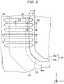
- FIG. 2 is an enlarged view of an "A" portion in the case where the resin frame 20 and the pair of separators 40 of FIG. 1 are joined together.
- the vicinity of the manifolds 30 through which hydrogen gas flows is illustrated.
- the resin frame 20 includes gas introduction parts 51 in the vicinity of the resin-frame-side manifold 30a.
- the gas introduction parts 51 serve to introduce hydrogen gas from the manifolds 30 into the gas introduction channels 50.
- the gas introduction part 51 is an end portion of each gas introduction channel 50 which is closer to the manifolds 30. More specifically, the gas introduction part 51 is an end portion of the gas introduction channel 50 which extends into the separator-side manifolds 30b, as viewed in the lamination direction (z-axis direction) of the separators 40 on the resin frame 20.
- the length L1 of each of the gas introduction parts 51 is the same length.
- the length L1 may be determined as desired provided that it is larger than zero.
- the length L1 is preferably determined such that the opening area of the gas introduction part 51 when it is viewed in the lamination direction (z-axis direction) is equal to or smaller than the channel cross-sectional area of the gas introduction channel 50.
- the length L2 from the end portion 52 of the gas introduction part 51 to an edge of the resin-frame-side manifold 30a may also be determined as desired provided that it is larger than zero, and it does not excessively impede flow of reaction gas in the manifolds 30.
- the ratio of the width W of the gas introduction channel 50 to the distance D between adjacent ones of the gas introduction channels 50 is preferably in the range of 0.5 to 3.0
- FIG. 3 is a cross-sectional view taken along line III-III in FIG. 2 , and illustrates the case where two or more fuel cells 100 are stacked together.
- a gasket 60 is provided between the separator 40a of one of the fuel cells 100 and the separator 40b of the other fuel cell 100.
- the gasket 60 is bonded to a recessed portion 43 of the separator 40a provided around the separator-side manifold 30b, more specifically, the recessed portion 43 provided at a position of the separator 40a which faces the gas introduction channels 50.
- a surface of the recessed portion 43 opposite to the gasket 60 is bonded to the resin frame 20.
- a recessed portion 44 is also formed in the separator 40b, and its bottom is bonded to the resin frame 20. End portions of the separators 40a, 40b are respectively spaced apart from the resin frame 20 in the lamination direction (z-axis direction), and protrude toward the insides of the manifolds 30.
- the gasket 60 is formed of silicone rubber, for example. Coolant channels through which the coolant from the coolant manifolds 31 flows are formed between adjacent ones of the fuel cells 100, and the coolant channels are sealed by the gasket 60.
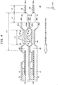
- FIG. 4 is a cross-sectional view taken along line IV-IV in FIG. 2 , and illustrates the case where two or more fuel cells 100 are stacked together. More specifically, the cross-sectional view of FIG. 4 is obtained by cutting the fuel cells 100 along one of the gas introduction channels 50.
- the length L3 (width) of the recessed portions 43, 44 as measured along the direction of flow of gas in the gas introduction channels 50 is shorter than the length L4 of the gas introduction channels 50.
- each of the gas introduction channels 50 is provided at a position opposed to the lower surface of the corresponding recessed portion 43.
- the gas introduction channel 50 permits hydrogen gas to flow from the manifolds 30 into the power generating body 10. More specifically, hydrogen gas flows from the manifolds 30 into the gas introduction channels 50 via the gas introduction parts 51. Then, the hydrogen gas is distributed to the respective flow channels 41 via the distribution flow channels 42, and supplied to the anode side of the power generating body 10.
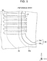
- FIG. 5 is a reference view showing the structure of the "A" portion of FIG. 1 when the end portions 52 of the gas introduction parts 51 closer to the manifolds 30 in FIG. 2 are cut off.
- the structure in the case where the length L2 is zero is illustrated.
- the gas introduction parts 51 may bend or flop in the y-axis direction, for example, and the gas introduction channels 50 may be partially closed.
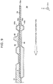
- FIG. 6 is a reference view showing the structure of a portion corresponding to the cross-section ( FIG. 4 ) taken along line IV-IV in FIG. 2 , in the case where the gas introduction channels 50 do not extend into the separator-side manifold 30b.
- an inlet through which the reaction gas is introduced may be closed or blocked, as indicated in the lower section of FIG. 6 . Therefore, variation in the pressure loss is increased, and the voltage may become unstable.
- the gas introduction channels 50 formed in the resin frame 20 extend into the separator-side manifolds 30b; therefore, even when the position of the resin frame 20 relative to the separators 40 is shifted due to a manufacturing error, for example, the inlet is less likely or unlikely to be closed or blocked. Accordingly, variation in the pressure loss at the time of introduction of reaction gas into the fuel cell 100 can be reduced or eliminated.
- the gas introduction channels 50 are formed between the resin-frame-side manifold 30a and the opening 21, and the end portions 52 of the gas introduction parts 51 are connected; therefore, the gas introduction parts 51 are prevented from being partially closed due to bending (flopping) of the gas introduction parts 51 in the y-axis direction.
- the length L1 of the gas introduction parts 51 is the same length, variation in the pressure loss among the gas introduction channels 50 can be reduced or eliminated.
- the distribution flow channels 42 are provided between the resin frame 20 and the separators 40, the reaction gas introduced from the gas introduction channels 50 can be distributed to a larger number of flow channels 41, and the power generation efficiency can be improved. With the distribution flow channels 42 thus provided, even when the position of the resin frame 20 relative to the separators 40 is shifted, the end portions of the gas introduction channels 50 closer to the separators 40 are less likely or unlikely to be closed.
- the separators 40a, 40b have respective recessed portions 43, 44; therefore, the total thickness of the two or more fuel cells 100 stacked together can be reduced by an amount corresponding to the thickness of the recessed portions. Therefore, the thickness of the fuel cells 100 stacked together can be prevented from being excessively increased. While the separators 40a, 40b have respective recessed portions 43, 44 in this embodiment, either one of the separator 40a and the separator 40b may have a recessed portion. Also, the recessed portions 43, 44 may be omitted.
- the structure of the gas introduction channels 50 on the side where hydrogen gas flows into the power generating body 10 has been described above.
- the structure of the gas introduction channels 50 on the side where oxygen gas flows into the power generating body 10 may be similar to the structure of the gas introduction channels 50 as described above.
- the structure of gas discharge channels on the side where reaction gas is discharged from the power generating body 10 may be similar to the structure of the gas introduction channels 50 as described above.
- FIG. 7 is an enlarged view of a first modified example corresponding to the enlarged view ( FIG. 2 ) of the "A" portion, which illustrates the case where the resin frame 20 and the pair of separators 40 of FIG. 1 are joined together.
- the gas introduction channels 50 are formed in parallel with each other, when viewed in the direction (z-axis direction) of lamination of the separators 40 on the resin frame 20.
- the gas introduction channels 50 may be formed such that some of the channels 50 are arranged in a fan-like form against the manifolds 30.
- the resin frame 20 has a plurality of gas introduction channels 50, and the length L1 of all of the gas introduction parts 51 is the same length.
- the gas introduction parts 51 of some of the gas introduction channels 50 may have a different length or lengths.
- the fuel cell 100 has the distribution flow channels 42 that distribute reaction gas supplied from the gas introduction channels 50 to the flow channels 41.
- the fuel cell 100 may not have the distribution flow channels 42, and each of the gas introduction channels 50 may be directly connected to a corresponding one of the flow channels 41.
- FIG. 8 and FIG. 9 are cross-sectional views of a fourth modified example, which correspond to the cross-sectional view ( FIG. 3 ) taken along line III-III in FIG. 2 .
- the end portions of the separators 40 at the peripheral edges of the manifolds 30 are respectively spaced apart from the resin frame 20 in the lamination direction (z-axis direction), and protrude toward the interiors of the gas introduction channels 50.
- the end portions of the separators 40 at the peripheral edges of the manifolds 30 may not be spaced apart from the resin frame 20.
- the end portions of the separators 40 at the peripheral edges of the manifolds 30 may be spaced apart from the resin frame 20 in the lamination direction, and then contact with the resin frame 20 again, as they proceed toward the manifolds 30.
- the present invention is not limited to the above embodiment and modified examples, but may be realized with various arrangements, without departing from its principle.
- the technical features in the embodiment and modified examples which correspond to the technical features described in the "SUMMARY OF THE INVENTION" above, may be replaced or combined as appropriate, so as to solve the problem as described above, or achieve a part or all of the above-described effects.
- the technical features may be deleted as appropriate, if they are not described as being essential to the invention in this specification.
Landscapes
- Life Sciences & Earth Sciences (AREA)
- Engineering & Computer Science (AREA)
- Manufacturing & Machinery (AREA)
- Sustainable Development (AREA)
- Sustainable Energy (AREA)
- Chemical & Material Sciences (AREA)
- Chemical Kinetics & Catalysis (AREA)
- Electrochemistry (AREA)
- General Chemical & Material Sciences (AREA)
- Fuel Cell (AREA)
Abstract
Description
- The invention relates to a fuel cell.
- A fuel cell having a resin frame that is placed at the outer periphery of a membrane electrode assembly, and is sandwiched between a pair of separators, is known (see Japanese Patent Application Publication No.
2014-063727 JP 2014-063727 A - For example, in
JP 2014-063727 A FIG. 6 , an inlet through which reaction gas is introduced may be closed or blocked, as shown in the lower section ofFIG. 6 , if the position of the resin frame relative to the separators is shifted due to a manufacturing error, for example. Therefore, variations may arise in a pressure loss that appears when reaction gas is led to the membrane electrode assembly, and the voltage of the fuel cell may become unstable. Thus, a technology that can reduce or eliminate the variation in the pressure loss at the time of introduction of reaction gas into the fuel cell has been desired. - One aspect of the invention is concerned with a fuel cell having a power generating body including a membrane electrode assembly, a resin frame placed around the power generating body, and a pair of separators laminated on the resin frame so as to sandwich the power generating body and the resin frame. The resin frame has a resin-frame-side manifold in which reaction gas flows in a direction passing through the resin frame, an opening that holds the power generating body, and a gas introduction channel formed through the resin frame between the resin-frame-side manifold and the opening. The pair of separators has a separator-side manifold through which the reaction gas flows, and the separator-side manifold is provided at a position corresponding to the resin-frame-side manifold as viewed in a lamination direction. The gas introduction channel has a gas introduction part that extends into the separator-side manifold, when viewed in the lamination direction. In the fuel cell thus constructed, the gas introduction channel formed in the resin frame extends into the separator-side manifold. Therefore, even when the position of the resin frame relative to the separators is shifted due to a manufacturing error, for example, an inlet through which reaction gas is introduced can be prevented from being closed or blocked. Accordingly, variation in a pressure loss at the time of introduction of reaction gas into the fuel cell can be reduced or eliminated.
- At least one of the pair of separators may have a recessed portion at a position facing the gas introduction channel, and the length of the recessed portion along a direction of gas flow in the gas introduction channel may be shorter than the length of the gas introduction channel. In the fuel cell thus constructed, the total thickness of a plurality of fuel cells stacked together can be reduced by an amount corresponding to the thickness of the recessed portions; therefore, the thickness can be prevented from being excessively increased.
- The resin frame may have a plurality of gas introduction channels between the resin-frame-side manifold and the opening, and each of the plurality of gas introduction channels may be the above-indicated gas introduction channel of the resin frame. The gas introduction parts of at least a part of the plurality of gas introduction channels may have substantially the same length. With the fuel cell thus constructed, variation in the pressure loss among the gas introduction channels can be reduced or eliminated.
- In the fuel cell as described above, a plurality of flow channels that permit the reaction gas to flow into the power generating body may be connected with the gas introduction channel, between the pair of separators and the resin frame, and the pair of separators may have a distribution flow channel that distributes the reaction gas supplied from the gas introduction channel to the flow channels. With the fuel cell thus constructed, the reaction gas introduced from the gas introduction channel can be distributed to a larger number of flow channels; therefore, the power generation efficiency can be improved.
- The present invention may be implemented in various forms. For example, the invention may be implemented in the form of a fuel cell stack that consists of a plurality of fuel cells stacked together, or a fuel cell, or in the form of a method of producing the fuel cell.
- Features, advantages, and technical and industrial significance of exemplary embodiments of the invention will be described below with reference to the accompanying drawings, in which like numerals denote like elements, and wherein:
-
FIG. 1 is an explanatory exploded view showing a fuel cell according to one embodiment of the invention; -
FIG. 2 is an enlarged view of "A" portion ofFIG. 1 ; -
FIG. 3 is a cross-sectional view taken along line III-III inFIG. 2 ; -
FIG. 4 is a cross-sectional view taken along line IV-IV inFIG. 2 ; -
FIG. 5 is a reference view of the "A" portion ofFIG. 2 ; -
FIG. 6 is a reference view of a cross-section taken along line IV-IV inFIG. 2 ; -
FIG. 7 is an enlarged view of the "A" portion ofFIG. 1 , showing a first modified example; -
FIG. 8 is a cross-sectional view taken along line IV-IV inFIG. 2 , showing a fourth modified example; and -
FIG. 9 is a cross-sectional view taken along line IV-IV inFIG. 2 , showing the fourth modified example. -
FIG. 1 is an explanatory exploded view of afuel cell 100 according to one embodiment of the invention. Thefuel cell 100 is a polymer electrolyte fuel cell that is supplied with hydrogen and oxygen as reaction gases, and generates electric power. Thefuel cell 100 includes a power generatingbody 10, aresin frame 20, a pair ofseparators coolant manifolds 31,flow channels 41, anddistribution flow channels 42. - The power generating
body 10 includes an electrolyte membrane (not shown), catalyst layers (not shown) formed adjacent to the opposite surfaces of the electrolyte membrane, and gas diffusion layers (not shown). The electrolyte membrane is a solid polymer thin film that shows good protonic conductivity when it is in a wet state. The electrolyte membrane is provided by an ion-exchange membrane of fluorine-based resin, for example. The catalyst layer includes a catalyst that promotes chemical reaction between hydrogen and oxygen, and carbon particles that carry the catalyst. The electrolyte membrane and the catalyst layers are assembled together to form a membrane electrode assembly (MEA). - The gas diffusion layers are provided adjacent to corresponding surfaces of the catalyst layers. The gas diffusion layers serve to diffuse reaction gas used for electrode reaction, along a planar direction of the electrolyte membrane, and are formed of a porous base material for diffusion layers. As the diffusion-layer base material, porous base materials having electrical conductivity and gas diffusibility, including carbon fiber base materials, graphitic fiber base materials, and foam metals, may be used. The electrolyte membrane, catalyst layers, and the gas diffusion layers are assembled together to form a membrane electrode gas-diffusion-layer assembly (MEGA).
- The
resin frame 20 is a frame-like resin member placed around the power generatingbody 10. In this embodiment, polyethylene terephthalate (PET) is used for the resin member. However, as the resin member, various thermoplastic resin members, such as polypropylene and polyethylene, may also be used. Theresin frame 20 has an opening 21, and resin-frame-side manifolds 30a. Theresin frame 20 holds the power generatingbody 10 in the opening 21. The reaction gas flows through the resin-frame-side manifolds 30a, in a direction (z-axis direction) that extends through theresin frame 20. - The
resin frame 20 includes a plurality ofgas introduction channels 50 between each of the resin-frame-side manifolds 30a and the opening 21. Thegas introduction channels 50 are formed through theresin frame 20. With thegas introduction channels 50 thus formed through theresin frame 20, the thickness of theresin frame 20, and consequently, the thickness of thefuel cell 100, can be reduced, as compared with the case where grooves are formed in a surface of theresin frame 20 to form gas introduction channels. In another embodiment, theresin frame 20 may have only onegas introduction channel 50 between each resin-frame-side manifold 30a and the opening 21. - The above-mentioned pair of
separators resin frame 20 so as to sandwich the power generatingbody 10 including the membrane electrode assembly, and theresin frame 20. Each of theseparators separator 40a is a cathode-side separator, and theseparator 40b is an anode-side separator. In this embodiment, theseparator 40a and theseparator 40b will be collectively called "separators 40". Theseparators 40 have separator-side manifolds 30b through which reaction gas flows. - The separator-
side manifolds 30b are provided at positions corresponding to the resin-frame-side manifolds 30a as viewed in the lamination direction (z-axis direction). The corresponding positions as viewed in the lamination direction mean substantially the same positions in the planar direction (x-axis direction and y-axis direction). In this embodiment, the opening area of the resin-frame-side manifold 30a is smaller than the opening area of the separator-side manifold 30b. In this embodiment, the resin-frame-side manifolds 30a and the separator-side manifolds 30b will be collectively called "manifolds 30". Themanifolds 30 communicate theresin frame 20 with theseparators 40, and the reaction gas flows through themanifolds 30. The coolant manifolds 31 communicate theresin frame 20 with theseparators 40, and coolant flows through the coolant manifolds 31. - The
flow channels 41 are formed between theseparators 40 and theresin frame 20. Theflow channels 41 permit the reaction gas to flow into thepower generating body 10. Thedistribution flow channels 42 distribute the reaction gas supplied from thegas introduction channels 50, to theflow channels 41. -
FIG. 2 is an enlarged view of an "A" portion in the case where theresin frame 20 and the pair ofseparators 40 ofFIG. 1 are joined together. In the enlarged view ofFIG. 2 , the vicinity of themanifolds 30 through which hydrogen gas flows is illustrated. As shown inFIG. 2 , theresin frame 20 includesgas introduction parts 51 in the vicinity of the resin-frame-side manifold 30a. Thegas introduction parts 51 serve to introduce hydrogen gas from themanifolds 30 into thegas introduction channels 50. Thegas introduction part 51 is an end portion of eachgas introduction channel 50 which is closer to themanifolds 30. More specifically, thegas introduction part 51 is an end portion of thegas introduction channel 50 which extends into the separator-side manifolds 30b, as viewed in the lamination direction (z-axis direction) of theseparators 40 on theresin frame 20. - The length L1 of each of the
gas introduction parts 51, more specifically, a distance from an edge of the separator-side manifold 30b to anend portion 52 of thegas introduction part 51, is the same length. The length L1 may be determined as desired provided that it is larger than zero. For example, the length L1 is preferably determined such that the opening area of thegas introduction part 51 when it is viewed in the lamination direction (z-axis direction) is equal to or smaller than the channel cross-sectional area of thegas introduction channel 50. The length L2 from theend portion 52 of thegas introduction part 51 to an edge of the resin-frame-side manifold 30a may also be determined as desired provided that it is larger than zero, and it does not excessively impede flow of reaction gas in themanifolds 30. The ratio of the width W of thegas introduction channel 50 to the distance D between adjacent ones of thegas introduction channels 50 is preferably in the range of 0.5 to 3.0 -
FIG. 3 is a cross-sectional view taken along line III-III inFIG. 2 , and illustrates the case where two ormore fuel cells 100 are stacked together. Between adjacent ones of thefuel cells 100, agasket 60 is provided between theseparator 40a of one of thefuel cells 100 and theseparator 40b of theother fuel cell 100. In this embodiment, thegasket 60 is bonded to a recessedportion 43 of theseparator 40a provided around the separator-side manifold 30b, more specifically, the recessedportion 43 provided at a position of theseparator 40a which faces thegas introduction channels 50. A surface of the recessedportion 43 opposite to thegasket 60 is bonded to theresin frame 20. A recessedportion 44 is also formed in theseparator 40b, and its bottom is bonded to theresin frame 20. End portions of theseparators resin frame 20 in the lamination direction (z-axis direction), and protrude toward the insides of the manifolds 30. - The
gasket 60 is formed of silicone rubber, for example. Coolant channels through which the coolant from thecoolant manifolds 31 flows are formed between adjacent ones of thefuel cells 100, and the coolant channels are sealed by thegasket 60. -
FIG. 4 is a cross-sectional view taken along line IV-IV inFIG. 2 , and illustrates the case where two ormore fuel cells 100 are stacked together. More specifically, the cross-sectional view ofFIG. 4 is obtained by cutting thefuel cells 100 along one of thegas introduction channels 50. The length L3 (width) of the recessedportions gas introduction channels 50 is shorter than the length L4 of thegas introduction channels 50. Also, each of thegas introduction channels 50 is provided at a position opposed to the lower surface of the corresponding recessedportion 43. - As indicated by an arrow in
FIG. 4 , thegas introduction channel 50 permits hydrogen gas to flow from themanifolds 30 into thepower generating body 10. More specifically, hydrogen gas flows from themanifolds 30 into thegas introduction channels 50 via thegas introduction parts 51. Then, the hydrogen gas is distributed to therespective flow channels 41 via thedistribution flow channels 42, and supplied to the anode side of thepower generating body 10. -
FIG. 5 is a reference view showing the structure of the "A" portion ofFIG. 1 when theend portions 52 of thegas introduction parts 51 closer to themanifolds 30 inFIG. 2 are cut off. In other words, the structure in the case where the length L2 is zero is illustrated. In this structure, when reaction gas is introduced, thegas introduction parts 51 may bend or flop in the y-axis direction, for example, and thegas introduction channels 50 may be partially closed. -
FIG. 6 is a reference view showing the structure of a portion corresponding to the cross-section (FIG. 4 ) taken along line IV-IV inFIG. 2 , in the case where thegas introduction channels 50 do not extend into the separator-side manifold 30b. With this structure, when the position of theresin frame 20 relative to theseparators 40 is shifted in a direction of an arrow (-x-axis direction) inFIG. 6 due to a manufacturing error, for example, an inlet through which the reaction gas is introduced may be closed or blocked, as indicated in the lower section ofFIG. 6 . Therefore, variation in the pressure loss is increased, and the voltage may become unstable. - As compared with the structures shown in
FIG. 5 andFIG. 6 , in thefuel cell 100 of this embodiment, thegas introduction channels 50 formed in theresin frame 20 extend into the separator-side manifolds 30b; therefore, even when the position of theresin frame 20 relative to theseparators 40 is shifted due to a manufacturing error, for example, the inlet is less likely or unlikely to be closed or blocked. Accordingly, variation in the pressure loss at the time of introduction of reaction gas into thefuel cell 100 can be reduced or eliminated. Also, thegas introduction channels 50 are formed between the resin-frame-side manifold 30a and theopening 21, and theend portions 52 of thegas introduction parts 51 are connected; therefore, thegas introduction parts 51 are prevented from being partially closed due to bending (flopping) of thegas introduction parts 51 in the y-axis direction. - Also, in this embodiment, since the length L1 of the
gas introduction parts 51 is the same length, variation in the pressure loss among thegas introduction channels 50 can be reduced or eliminated. Further, since thedistribution flow channels 42 are provided between theresin frame 20 and theseparators 40, the reaction gas introduced from thegas introduction channels 50 can be distributed to a larger number offlow channels 41, and the power generation efficiency can be improved. With thedistribution flow channels 42 thus provided, even when the position of theresin frame 20 relative to theseparators 40 is shifted, the end portions of thegas introduction channels 50 closer to theseparators 40 are less likely or unlikely to be closed. - Also, in this embodiment, the
separators portions more fuel cells 100 stacked together can be reduced by an amount corresponding to the thickness of the recessed portions. Therefore, the thickness of thefuel cells 100 stacked together can be prevented from being excessively increased. While theseparators portions separator 40a and theseparator 40b may have a recessed portion. Also, the recessedportions - In the illustrated embodiment, the structure of the
gas introduction channels 50 on the side where hydrogen gas flows into thepower generating body 10 has been described above. However, the structure of thegas introduction channels 50 on the side where oxygen gas flows into thepower generating body 10 may be similar to the structure of thegas introduction channels 50 as described above. Also, the structure of gas discharge channels on the side where reaction gas is discharged from thepower generating body 10 may be similar to the structure of thegas introduction channels 50 as described above. -
FIG. 7 is an enlarged view of a first modified example corresponding to the enlarged view (FIG. 2 ) of the "A" portion, which illustrates the case where theresin frame 20 and the pair ofseparators 40 ofFIG. 1 are joined together. In the illustrated embodiment, thegas introduction channels 50 are formed in parallel with each other, when viewed in the direction (z-axis direction) of lamination of theseparators 40 on theresin frame 20. On the other hand, as shown inFIG. 7 , thegas introduction channels 50 may be formed such that some of thechannels 50 are arranged in a fan-like form against themanifolds 30. - In the illustrated embodiment, the
resin frame 20 has a plurality ofgas introduction channels 50, and the length L1 of all of thegas introduction parts 51 is the same length. On the other hand, thegas introduction parts 51 of some of thegas introduction channels 50 may have a different length or lengths. - In the illustrated embodiment, the
fuel cell 100 has thedistribution flow channels 42 that distribute reaction gas supplied from thegas introduction channels 50 to theflow channels 41. On the other hand, thefuel cell 100 may not have thedistribution flow channels 42, and each of thegas introduction channels 50 may be directly connected to a corresponding one of theflow channels 41. -
FIG. 8 andFIG. 9 are cross-sectional views of a fourth modified example, which correspond to the cross-sectional view (FIG. 3 ) taken along line III-III inFIG. 2 . In the illustrated embodiment, the end portions of theseparators 40 at the peripheral edges of themanifolds 30 are respectively spaced apart from theresin frame 20 in the lamination direction (z-axis direction), and protrude toward the interiors of thegas introduction channels 50. On the other hand, as shown inFIG. 8 , the end portions of theseparators 40 at the peripheral edges of themanifolds 30 may not be spaced apart from theresin frame 20. Also, as shown inFIG. 9 , the end portions of theseparators 40 at the peripheral edges of themanifolds 30 may be spaced apart from theresin frame 20 in the lamination direction, and then contact with theresin frame 20 again, as they proceed toward themanifolds 30. - The present invention is not limited to the above embodiment and modified examples, but may be realized with various arrangements, without departing from its principle. For example, the technical features in the embodiment and modified examples, which correspond to the technical features described in the "SUMMARY OF THE INVENTION" above, may be replaced or combined as appropriate, so as to solve the problem as described above, or achieve a part or all of the above-described effects. Also, the technical features may be deleted as appropriate, if they are not described as being essential to the invention in this specification.
Claims (4)
- A fuel cell comprising:a power generating body (10) including a membrane electrode assembly;a resin frame (20) placed around the power generating body (10); anda pair of separators (40a, 40b) laminated on the resin frame so as to sandwich the power generating body (10) and the resin frame (20),wherein the resin frame (20) has a resin-frame-side manifold (30a) in which reaction gas flows in a direction passing through the resin frame (20), an opening (21) that holds the power generating body (10), and a gas introduction channel (50) formed through the resin frame (20) between the resin-frame-side manifold (30a) and the opening (21),the pair of separators (40a, 40b) has a separator-side manifold (30b) through which the reaction gas flows, the separator-side manifold (30b) being provided at a position corresponding to the resin-frame-side manifold (30a) as viewed in a lamination direction, andthe gas introduction channel (50) has a gas introduction part (51) that extends into the separator-side manifold (30b), when viewed in the lamination direction.
- The fuel cell according to claim 1, wherein:at least one of the pair of separators (40a, 40b) has a recessed portion (43) at a position facing the gas introduction channel (50); anda length of the recessed portion (43) along a direction of gas flow in the gas introduction channel (50) is shorter than a length of the gas introduction channel (50).
- The fuel cell according to claim 1 or 2, wherein:the resin frame (20) has a plurality of gas introduction channels (50) between the resin-frame-side manifold (30a) and the opening (21), each of the plurality of gas introduction channels (50) being the gas introduction channel (50) of the resin frame; andthe gas introduction parts (51) of at least a part of the plurality of gas introduction channels (50) have substantially the same length.
- The fuel cell according to any one of claims 1 to 3, wherein:a plurality of flow channels (41) that permit the reaction gas to flow into the power generating body (10) are connected with the gas introduction channel (50), between the pair of separators (40a, 40b) and the resin frame (20); andthe pair of separators (40a, 40b) has a distribution flow channel (42) that distributes the reaction gas supplied from the gas introduction channel (50) to the flow channels (41).
Applications Claiming Priority (1)
| Application Number | Priority Date | Filing Date | Title |
|---|---|---|---|
| JP2017081042A JP6859823B2 (en) | 2017-04-17 | 2017-04-17 | Fuel cell |
Publications (2)
| Publication Number | Publication Date |
|---|---|
| EP3392952A1 true EP3392952A1 (en) | 2018-10-24 |
| EP3392952B1 EP3392952B1 (en) | 2022-05-11 |
Family
ID=61965773
Family Applications (1)
| Application Number | Title | Priority Date | Filing Date |
|---|---|---|---|
| EP18166548.0A Active EP3392952B1 (en) | 2017-04-17 | 2018-04-10 | Fuel cell |
Country Status (8)
| Country | Link |
|---|---|
| US (1) | US10826097B2 (en) |
| EP (1) | EP3392952B1 (en) |
| JP (1) | JP6859823B2 (en) |
| KR (1) | KR102173663B1 (en) |
| CN (1) | CN108736039B (en) |
| BR (1) | BR102018007184A2 (en) |
| CA (1) | CA3001024C (en) |
| RU (1) | RU2679898C1 (en) |
Families Citing this family (4)
| Publication number | Priority date | Publication date | Assignee | Title |
|---|---|---|---|---|
| JP7110971B2 (en) * | 2018-12-21 | 2022-08-02 | トヨタ自動車株式会社 | fuel cell |
| WO2020209047A1 (en) * | 2019-04-09 | 2020-10-15 | Nok株式会社 | Separator-integrated gasket |
| JP7188365B2 (en) * | 2019-11-27 | 2022-12-13 | トヨタ自動車株式会社 | Fuel cell and manufacturing method thereof |
| JP7634028B2 (en) * | 2023-01-13 | 2025-02-20 | 本田技研工業株式会社 | Power generation cells and fuel cell stacks |
Citations (4)
| Publication number | Priority date | Publication date | Assignee | Title |
|---|---|---|---|---|
| US20050277013A1 (en) * | 2004-06-14 | 2005-12-15 | Kenji Yamaga | Solid polymer type fuel cell, metal separator for fuel cell, and kit for fuel cell |
| JP2014063727A (en) | 2012-08-31 | 2014-04-10 | Honda Motor Co Ltd | Fuel cell |
| JP2015195153A (en) * | 2014-03-31 | 2015-11-05 | トヨタ車体株式会社 | Fuel cell |
| US20160336605A1 (en) * | 2014-01-15 | 2016-11-17 | Ngk Spark Plug Co. Ltd. | Fuel cell cassette and fuel cell stack |
Family Cites Families (10)
| Publication number | Priority date | Publication date | Assignee | Title |
|---|---|---|---|---|
| GB2437994A (en) * | 2006-05-13 | 2007-11-14 | Intelligent Energy Ltd | Gaskets for fuel cells |
| JP4585036B2 (en) * | 2008-05-30 | 2010-11-24 | パナソニック株式会社 | MEA member and polymer electrolyte fuel cell |
| JP5560728B2 (en) * | 2010-01-19 | 2014-07-30 | トヨタ車体株式会社 | Fuel cell |
| JP5386541B2 (en) * | 2011-05-20 | 2014-01-15 | 本田技研工業株式会社 | Fuel cell |
| JP2013033650A (en) * | 2011-08-02 | 2013-02-14 | Honda Motor Co Ltd | Membrane electrode assembly for solid electrolyte fuel cell |
| RU114808U1 (en) * | 2011-10-25 | 2012-04-10 | Российская Федерация, От Имени Которой Выступает Министерство Промышленности И Торговли Российской Федерации | FULL-SCALE FUEL CELL WITH A SOLID-POLYMER ELECTROLYTE FOR BATTERIES OF FUEL CELLS WITH A POWER OF ABOUT 60 kW |
| WO2013136816A1 (en) * | 2012-03-15 | 2013-09-19 | Nissan Motor Co., Ltd. | Fuel cell |
| JP6068371B2 (en) * | 2014-01-22 | 2017-01-25 | 本田技研工業株式会社 | Fuel cell |
| JP6177212B2 (en) * | 2014-10-07 | 2017-08-09 | 本田技研工業株式会社 | Fuel cell |
| JP2017117780A (en) | 2015-12-17 | 2017-06-29 | トヨタ自動車株式会社 | Fuel battery module |
-
2017
- 2017-04-17 JP JP2017081042A patent/JP6859823B2/en active Active
-
2018
- 2018-04-10 BR BR102018007184A patent/BR102018007184A2/en not_active Application Discontinuation
- 2018-04-10 EP EP18166548.0A patent/EP3392952B1/en active Active
- 2018-04-11 CA CA3001024A patent/CA3001024C/en active Active
- 2018-04-11 US US15/950,406 patent/US10826097B2/en active Active
- 2018-04-12 KR KR1020180042597A patent/KR102173663B1/en active Active
- 2018-04-13 CN CN201810329829.4A patent/CN108736039B/en active Active
- 2018-04-16 RU RU2018113723A patent/RU2679898C1/en active
Patent Citations (4)
| Publication number | Priority date | Publication date | Assignee | Title |
|---|---|---|---|---|
| US20050277013A1 (en) * | 2004-06-14 | 2005-12-15 | Kenji Yamaga | Solid polymer type fuel cell, metal separator for fuel cell, and kit for fuel cell |
| JP2014063727A (en) | 2012-08-31 | 2014-04-10 | Honda Motor Co Ltd | Fuel cell |
| US20160336605A1 (en) * | 2014-01-15 | 2016-11-17 | Ngk Spark Plug Co. Ltd. | Fuel cell cassette and fuel cell stack |
| JP2015195153A (en) * | 2014-03-31 | 2015-11-05 | トヨタ車体株式会社 | Fuel cell |
Also Published As
| Publication number | Publication date |
|---|---|
| CA3001024C (en) | 2020-04-21 |
| RU2679898C1 (en) | 2019-02-14 |
| KR20180116753A (en) | 2018-10-25 |
| KR102173663B1 (en) | 2020-11-03 |
| US20180301727A1 (en) | 2018-10-18 |
| CN108736039A (en) | 2018-11-02 |
| CN108736039B (en) | 2021-10-19 |
| BR102018007184A2 (en) | 2018-10-30 |
| EP3392952B1 (en) | 2022-05-11 |
| CA3001024A1 (en) | 2018-10-17 |
| JP2018181661A (en) | 2018-11-15 |
| JP6859823B2 (en) | 2021-04-14 |
| US10826097B2 (en) | 2020-11-03 |
Similar Documents
| Publication | Publication Date | Title |
|---|---|---|
| CA2653876C (en) | Fuel cell having gas channel-forming member and method of producing the same | |
| US10826084B2 (en) | Fuel cell | |
| US20110300465A1 (en) | Fuel cell stack | |
| US20220173413A1 (en) | Fuel cell | |
| CN101395751A (en) | Cell stack and fuel cell provided with the cell stack | |
| CA3001024C (en) | Resin frame and separator configuration in a fuel cell | |
| US9559376B2 (en) | Fuel cell with an electrolyte membrane and gas diffusion layers | |
| US20100248085A1 (en) | Flow field plate of a fuel cell with airflow guiding gaskets | |
| US11145877B2 (en) | Fuel cell | |
| CN105591121B (en) | Fuel cell separator, fuel-cell single-cell and fuel cell | |
| US9490487B2 (en) | Fuel cell | |
| EP4084160B1 (en) | Separator for fuel battery | |
| US9368815B2 (en) | Fuel cell | |
| JP6519490B2 (en) | Fuel cell | |
| JP5809594B2 (en) | Fuel cell | |
| JP2008059760A (en) | Fuel cell and fuel cell manufacturing method | |
| JP6748451B2 (en) | Fuel cell stack | |
| JP2013222698A (en) | Fuel cell | |
| JP2010027381A (en) | Fuel cell | |
| JP6132697B2 (en) | Fuel cell | |
| JP2017050206A (en) | Fuel cell | |
| CN115224298A (en) | Membranes and fuel cell stacks for fuel cells | |
| JP2012003857A (en) | Fuel cell |
Legal Events
| Date | Code | Title | Description |
|---|---|---|---|
| PUAI | Public reference made under article 153(3) epc to a published international application that has entered the european phase |
Free format text: ORIGINAL CODE: 0009012 |
|
| STAA | Information on the status of an ep patent application or granted ep patent |
Free format text: STATUS: REQUEST FOR EXAMINATION WAS MADE |
|
| 17P | Request for examination filed |
Effective date: 20180410 |
|
| AK | Designated contracting states |
Kind code of ref document: A1 Designated state(s): AL AT BE BG CH CY CZ DE DK EE ES FI FR GB GR HR HU IE IS IT LI LT LU LV MC MK MT NL NO PL PT RO RS SE SI SK SM TR |
|
| AX | Request for extension of the european patent |
Extension state: BA ME |
|
| RAP1 | Party data changed (applicant data changed or rights of an application transferred) |
Owner name: TOYOTA JIDOSHA KABUSHIKI KAISHA |
|
| STAA | Information on the status of an ep patent application or granted ep patent |
Free format text: STATUS: EXAMINATION IS IN PROGRESS |
|
| 17Q | First examination report despatched |
Effective date: 20200331 |
|
| GRAP | Despatch of communication of intention to grant a patent |
Free format text: ORIGINAL CODE: EPIDOSNIGR1 |
|
| STAA | Information on the status of an ep patent application or granted ep patent |
Free format text: STATUS: GRANT OF PATENT IS INTENDED |
|
| INTG | Intention to grant announced |
Effective date: 20220110 |
|
| RIN1 | Information on inventor provided before grant (corrected) |
Inventor name: KADONO, HIDEYA Inventor name: OKADA, SACHIO Inventor name: SATO, KENJI |
|
| GRAS | Grant fee paid |
Free format text: ORIGINAL CODE: EPIDOSNIGR3 |
|
| GRAA | (expected) grant |
Free format text: ORIGINAL CODE: 0009210 |
|
| STAA | Information on the status of an ep patent application or granted ep patent |
Free format text: STATUS: THE PATENT HAS BEEN GRANTED |
|
| RAP3 | Party data changed (applicant data changed or rights of an application transferred) |
Owner name: TOYOTA JIDOSHA KABUSHIKI KAISHA |
|
| AK | Designated contracting states |
Kind code of ref document: B1 Designated state(s): AL AT BE BG CH CY CZ DE DK EE ES FI FR GB GR HR HU IE IS IT LI LT LU LV MC MK MT NL NO PL PT RO RS SE SI SK SM TR |
|
| REG | Reference to a national code |
Ref country code: GB Ref legal event code: FG4D |
|
| REG | Reference to a national code |
Ref country code: CH Ref legal event code: EP |
|
| REG | Reference to a national code |
Ref country code: AT Ref legal event code: REF Ref document number: 1492232 Country of ref document: AT Kind code of ref document: T Effective date: 20220515 |
|
| REG | Reference to a national code |
Ref country code: DE Ref legal event code: R096 Ref document number: 602018035271 Country of ref document: DE |
|
| REG | Reference to a national code |
Ref country code: IE Ref legal event code: FG4D |
|
| REG | Reference to a national code |
Ref country code: NO Ref legal event code: T2 Effective date: 20220511 |
|
| REG | Reference to a national code |
Ref country code: LT Ref legal event code: MG9D |
|
| REG | Reference to a national code |
Ref country code: NL Ref legal event code: MP Effective date: 20220511 |
|
| REG | Reference to a national code |
Ref country code: AT Ref legal event code: MK05 Ref document number: 1492232 Country of ref document: AT Kind code of ref document: T Effective date: 20220511 |
|
| PG25 | Lapsed in a contracting state [announced via postgrant information from national office to epo] |
Ref country code: SE Free format text: LAPSE BECAUSE OF FAILURE TO SUBMIT A TRANSLATION OF THE DESCRIPTION OR TO PAY THE FEE WITHIN THE PRESCRIBED TIME-LIMIT Effective date: 20220511 Ref country code: PT Free format text: LAPSE BECAUSE OF FAILURE TO SUBMIT A TRANSLATION OF THE DESCRIPTION OR TO PAY THE FEE WITHIN THE PRESCRIBED TIME-LIMIT Effective date: 20220912 Ref country code: NL Free format text: LAPSE BECAUSE OF FAILURE TO SUBMIT A TRANSLATION OF THE DESCRIPTION OR TO PAY THE FEE WITHIN THE PRESCRIBED TIME-LIMIT Effective date: 20220511 Ref country code: LT Free format text: LAPSE BECAUSE OF FAILURE TO SUBMIT A TRANSLATION OF THE DESCRIPTION OR TO PAY THE FEE WITHIN THE PRESCRIBED TIME-LIMIT Effective date: 20220511 Ref country code: HR Free format text: LAPSE BECAUSE OF FAILURE TO SUBMIT A TRANSLATION OF THE DESCRIPTION OR TO PAY THE FEE WITHIN THE PRESCRIBED TIME-LIMIT Effective date: 20220511 Ref country code: GR Free format text: LAPSE BECAUSE OF FAILURE TO SUBMIT A TRANSLATION OF THE DESCRIPTION OR TO PAY THE FEE WITHIN THE PRESCRIBED TIME-LIMIT Effective date: 20220812 Ref country code: FI Free format text: LAPSE BECAUSE OF FAILURE TO SUBMIT A TRANSLATION OF THE DESCRIPTION OR TO PAY THE FEE WITHIN THE PRESCRIBED TIME-LIMIT Effective date: 20220511 Ref country code: ES Free format text: LAPSE BECAUSE OF FAILURE TO SUBMIT A TRANSLATION OF THE DESCRIPTION OR TO PAY THE FEE WITHIN THE PRESCRIBED TIME-LIMIT Effective date: 20220511 Ref country code: BG Free format text: LAPSE BECAUSE OF FAILURE TO SUBMIT A TRANSLATION OF THE DESCRIPTION OR TO PAY THE FEE WITHIN THE PRESCRIBED TIME-LIMIT Effective date: 20220811 Ref country code: AT Free format text: LAPSE BECAUSE OF FAILURE TO SUBMIT A TRANSLATION OF THE DESCRIPTION OR TO PAY THE FEE WITHIN THE PRESCRIBED TIME-LIMIT Effective date: 20220511 |
|
| PG25 | Lapsed in a contracting state [announced via postgrant information from national office to epo] |
Ref country code: RS Free format text: LAPSE BECAUSE OF FAILURE TO SUBMIT A TRANSLATION OF THE DESCRIPTION OR TO PAY THE FEE WITHIN THE PRESCRIBED TIME-LIMIT Effective date: 20220511 Ref country code: PL Free format text: LAPSE BECAUSE OF FAILURE TO SUBMIT A TRANSLATION OF THE DESCRIPTION OR TO PAY THE FEE WITHIN THE PRESCRIBED TIME-LIMIT Effective date: 20220511 Ref country code: LV Free format text: LAPSE BECAUSE OF FAILURE TO SUBMIT A TRANSLATION OF THE DESCRIPTION OR TO PAY THE FEE WITHIN THE PRESCRIBED TIME-LIMIT Effective date: 20220511 Ref country code: IS Free format text: LAPSE BECAUSE OF FAILURE TO SUBMIT A TRANSLATION OF THE DESCRIPTION OR TO PAY THE FEE WITHIN THE PRESCRIBED TIME-LIMIT Effective date: 20220911 |
|
| PG25 | Lapsed in a contracting state [announced via postgrant information from national office to epo] |
Ref country code: SM Free format text: LAPSE BECAUSE OF FAILURE TO SUBMIT A TRANSLATION OF THE DESCRIPTION OR TO PAY THE FEE WITHIN THE PRESCRIBED TIME-LIMIT Effective date: 20220511 Ref country code: SK Free format text: LAPSE BECAUSE OF FAILURE TO SUBMIT A TRANSLATION OF THE DESCRIPTION OR TO PAY THE FEE WITHIN THE PRESCRIBED TIME-LIMIT Effective date: 20220511 Ref country code: RO Free format text: LAPSE BECAUSE OF FAILURE TO SUBMIT A TRANSLATION OF THE DESCRIPTION OR TO PAY THE FEE WITHIN THE PRESCRIBED TIME-LIMIT Effective date: 20220511 Ref country code: EE Free format text: LAPSE BECAUSE OF FAILURE TO SUBMIT A TRANSLATION OF THE DESCRIPTION OR TO PAY THE FEE WITHIN THE PRESCRIBED TIME-LIMIT Effective date: 20220511 Ref country code: DK Free format text: LAPSE BECAUSE OF FAILURE TO SUBMIT A TRANSLATION OF THE DESCRIPTION OR TO PAY THE FEE WITHIN THE PRESCRIBED TIME-LIMIT Effective date: 20220511 Ref country code: CZ Free format text: LAPSE BECAUSE OF FAILURE TO SUBMIT A TRANSLATION OF THE DESCRIPTION OR TO PAY THE FEE WITHIN THE PRESCRIBED TIME-LIMIT Effective date: 20220511 |
|
| REG | Reference to a national code |
Ref country code: DE Ref legal event code: R097 Ref document number: 602018035271 Country of ref document: DE |
|
| PLBE | No opposition filed within time limit |
Free format text: ORIGINAL CODE: 0009261 |
|
| STAA | Information on the status of an ep patent application or granted ep patent |
Free format text: STATUS: NO OPPOSITION FILED WITHIN TIME LIMIT |
|
| PG25 | Lapsed in a contracting state [announced via postgrant information from national office to epo] |
Ref country code: AL Free format text: LAPSE BECAUSE OF FAILURE TO SUBMIT A TRANSLATION OF THE DESCRIPTION OR TO PAY THE FEE WITHIN THE PRESCRIBED TIME-LIMIT Effective date: 20220511 |
|
| 26N | No opposition filed |
Effective date: 20230214 |
|
| PG25 | Lapsed in a contracting state [announced via postgrant information from national office to epo] |
Ref country code: SI Free format text: LAPSE BECAUSE OF FAILURE TO SUBMIT A TRANSLATION OF THE DESCRIPTION OR TO PAY THE FEE WITHIN THE PRESCRIBED TIME-LIMIT Effective date: 20220511 |
|
| P01 | Opt-out of the competence of the unified patent court (upc) registered |
Effective date: 20230427 |
|
| REG | Reference to a national code |
Ref country code: DE Ref legal event code: R084 Ref document number: 602018035271 Country of ref document: DE |
|
| REG | Reference to a national code |
Ref country code: GB Ref legal event code: 746 Effective date: 20230731 |
|
| REG | Reference to a national code |
Ref country code: CH Ref legal event code: PL |
|
| PG25 | Lapsed in a contracting state [announced via postgrant information from national office to epo] |
Ref country code: LU Free format text: LAPSE BECAUSE OF NON-PAYMENT OF DUE FEES Effective date: 20230410 |
|
| REG | Reference to a national code |
Ref country code: BE Ref legal event code: MM Effective date: 20230430 |
|
| PG25 | Lapsed in a contracting state [announced via postgrant information from national office to epo] |
Ref country code: MC Free format text: LAPSE BECAUSE OF FAILURE TO SUBMIT A TRANSLATION OF THE DESCRIPTION OR TO PAY THE FEE WITHIN THE PRESCRIBED TIME-LIMIT Effective date: 20220511 |
|
| PG25 | Lapsed in a contracting state [announced via postgrant information from national office to epo] |
Ref country code: MC Free format text: LAPSE BECAUSE OF FAILURE TO SUBMIT A TRANSLATION OF THE DESCRIPTION OR TO PAY THE FEE WITHIN THE PRESCRIBED TIME-LIMIT Effective date: 20220511 Ref country code: LI Free format text: LAPSE BECAUSE OF NON-PAYMENT OF DUE FEES Effective date: 20230430 Ref country code: CH Free format text: LAPSE BECAUSE OF NON-PAYMENT OF DUE FEES Effective date: 20230430 |
|
| REG | Reference to a national code |
Ref country code: IE Ref legal event code: MM4A |
|
| PG25 | Lapsed in a contracting state [announced via postgrant information from national office to epo] |
Ref country code: BE Free format text: LAPSE BECAUSE OF NON-PAYMENT OF DUE FEES Effective date: 20230430 |
|
| PG25 | Lapsed in a contracting state [announced via postgrant information from national office to epo] |
Ref country code: IE Free format text: LAPSE BECAUSE OF NON-PAYMENT OF DUE FEES Effective date: 20230410 |
|
| PG25 | Lapsed in a contracting state [announced via postgrant information from national office to epo] |
Ref country code: IE Free format text: LAPSE BECAUSE OF NON-PAYMENT OF DUE FEES Effective date: 20230410 |
|
| PG25 | Lapsed in a contracting state [announced via postgrant information from national office to epo] |
Ref country code: BG Free format text: LAPSE BECAUSE OF FAILURE TO SUBMIT A TRANSLATION OF THE DESCRIPTION OR TO PAY THE FEE WITHIN THE PRESCRIBED TIME-LIMIT Effective date: 20220511 |
|
| PG25 | Lapsed in a contracting state [announced via postgrant information from national office to epo] |
Ref country code: BG Free format text: LAPSE BECAUSE OF FAILURE TO SUBMIT A TRANSLATION OF THE DESCRIPTION OR TO PAY THE FEE WITHIN THE PRESCRIBED TIME-LIMIT Effective date: 20220511 |
|
| PGFP | Annual fee paid to national office [announced via postgrant information from national office to epo] |
Ref country code: DE Payment date: 20250305 Year of fee payment: 8 |
|
| PGFP | Annual fee paid to national office [announced via postgrant information from national office to epo] |
Ref country code: NO Payment date: 20250409 Year of fee payment: 8 |
|
| PG25 | Lapsed in a contracting state [announced via postgrant information from national office to epo] |
Ref country code: CY Free format text: LAPSE BECAUSE OF FAILURE TO SUBMIT A TRANSLATION OF THE DESCRIPTION OR TO PAY THE FEE WITHIN THE PRESCRIBED TIME-LIMIT; INVALID AB INITIO Effective date: 20180410 |
|
| PG25 | Lapsed in a contracting state [announced via postgrant information from national office to epo] |
Ref country code: HU Free format text: LAPSE BECAUSE OF FAILURE TO SUBMIT A TRANSLATION OF THE DESCRIPTION OR TO PAY THE FEE WITHIN THE PRESCRIBED TIME-LIMIT; INVALID AB INITIO Effective date: 20180410 |
|
| PG25 | Lapsed in a contracting state [announced via postgrant information from national office to epo] |
Ref country code: TR Free format text: LAPSE BECAUSE OF FAILURE TO SUBMIT A TRANSLATION OF THE DESCRIPTION OR TO PAY THE FEE WITHIN THE PRESCRIBED TIME-LIMIT Effective date: 20220511 |
|
| PGFP | Annual fee paid to national office [announced via postgrant information from national office to epo] |
Ref country code: GB Payment date: 20260313 Year of fee payment: 9 |
|
| PGFP | Annual fee paid to national office [announced via postgrant information from national office to epo] |
Ref country code: IT Payment date: 20260320 Year of fee payment: 9 |
|
| PGFP | Annual fee paid to national office [announced via postgrant information from national office to epo] |
Ref country code: FR Payment date: 20260309 Year of fee payment: 9 |