EP3392942A1 - Fuel cell system - Google Patents
Fuel cell system Download PDFInfo
- Publication number
- EP3392942A1 EP3392942A1 EP16875241.8A EP16875241A EP3392942A1 EP 3392942 A1 EP3392942 A1 EP 3392942A1 EP 16875241 A EP16875241 A EP 16875241A EP 3392942 A1 EP3392942 A1 EP 3392942A1
- Authority
- EP
- European Patent Office
- Prior art keywords
- fuel cell
- electric power
- auxiliary machine
- coupled
- power supply
- Prior art date
- Legal status (The legal status is an assumption and is not a legal conclusion. Google has not performed a legal analysis and makes no representation as to the accuracy of the status listed.)
- Granted
Links
Images




Classifications
-
- H—ELECTRICITY
- H01—ELECTRIC ELEMENTS
- H01M—PROCESSES OR MEANS, e.g. BATTERIES, FOR THE DIRECT CONVERSION OF CHEMICAL ENERGY INTO ELECTRICAL ENERGY
- H01M8/00—Fuel cells; Manufacture thereof
- H01M8/04—Auxiliary arrangements, e.g. for control of pressure or for circulation of fluids
- H01M8/04298—Processes for controlling fuel cells or fuel cell systems
- H01M8/043—Processes for controlling fuel cells or fuel cell systems applied during specific periods
- H01M8/04303—Processes for controlling fuel cells or fuel cell systems applied during specific periods applied during shut-down
-
- B—PERFORMING OPERATIONS; TRANSPORTING
- B60—VEHICLES IN GENERAL
- B60L—PROPULSION OF ELECTRICALLY-PROPELLED VEHICLES; SUPPLYING ELECTRIC POWER FOR AUXILIARY EQUIPMENT OF ELECTRICALLY-PROPELLED VEHICLES; ELECTRODYNAMIC BRAKE SYSTEMS FOR VEHICLES IN GENERAL; MAGNETIC SUSPENSION OR LEVITATION FOR VEHICLES; MONITORING OPERATING VARIABLES OF ELECTRICALLY-PROPELLED VEHICLES; ELECTRIC SAFETY DEVICES FOR ELECTRICALLY-PROPELLED VEHICLES
- B60L1/00—Supplying electric power to auxiliary equipment of vehicles
-
- B—PERFORMING OPERATIONS; TRANSPORTING
- B60—VEHICLES IN GENERAL
- B60L—PROPULSION OF ELECTRICALLY-PROPELLED VEHICLES; SUPPLYING ELECTRIC POWER FOR AUXILIARY EQUIPMENT OF ELECTRICALLY-PROPELLED VEHICLES; ELECTRODYNAMIC BRAKE SYSTEMS FOR VEHICLES IN GENERAL; MAGNETIC SUSPENSION OR LEVITATION FOR VEHICLES; MONITORING OPERATING VARIABLES OF ELECTRICALLY-PROPELLED VEHICLES; ELECTRIC SAFETY DEVICES FOR ELECTRICALLY-PROPELLED VEHICLES
- B60L50/00—Electric propulsion with power supplied within the vehicle
- B60L50/50—Electric propulsion with power supplied within the vehicle using propulsion power supplied by batteries or fuel cells
- B60L50/60—Electric propulsion with power supplied within the vehicle using propulsion power supplied by batteries or fuel cells using power supplied by batteries
- B60L50/66—Arrangements of batteries
-
- B—PERFORMING OPERATIONS; TRANSPORTING
- B60—VEHICLES IN GENERAL
- B60L—PROPULSION OF ELECTRICALLY-PROPELLED VEHICLES; SUPPLYING ELECTRIC POWER FOR AUXILIARY EQUIPMENT OF ELECTRICALLY-PROPELLED VEHICLES; ELECTRODYNAMIC BRAKE SYSTEMS FOR VEHICLES IN GENERAL; MAGNETIC SUSPENSION OR LEVITATION FOR VEHICLES; MONITORING OPERATING VARIABLES OF ELECTRICALLY-PROPELLED VEHICLES; ELECTRIC SAFETY DEVICES FOR ELECTRICALLY-PROPELLED VEHICLES
- B60L50/00—Electric propulsion with power supplied within the vehicle
- B60L50/50—Electric propulsion with power supplied within the vehicle using propulsion power supplied by batteries or fuel cells
- B60L50/70—Electric propulsion with power supplied within the vehicle using propulsion power supplied by batteries or fuel cells using power supplied by fuel cells
- B60L50/71—Arrangement of fuel cells within vehicles specially adapted for electric vehicles
-
- B—PERFORMING OPERATIONS; TRANSPORTING
- B60—VEHICLES IN GENERAL
- B60L—PROPULSION OF ELECTRICALLY-PROPELLED VEHICLES; SUPPLYING ELECTRIC POWER FOR AUXILIARY EQUIPMENT OF ELECTRICALLY-PROPELLED VEHICLES; ELECTRODYNAMIC BRAKE SYSTEMS FOR VEHICLES IN GENERAL; MAGNETIC SUSPENSION OR LEVITATION FOR VEHICLES; MONITORING OPERATING VARIABLES OF ELECTRICALLY-PROPELLED VEHICLES; ELECTRIC SAFETY DEVICES FOR ELECTRICALLY-PROPELLED VEHICLES
- B60L50/00—Electric propulsion with power supplied within the vehicle
- B60L50/50—Electric propulsion with power supplied within the vehicle using propulsion power supplied by batteries or fuel cells
- B60L50/75—Electric propulsion with power supplied within the vehicle using propulsion power supplied by batteries or fuel cells using propulsion power supplied by both fuel cells and batteries
-
- B—PERFORMING OPERATIONS; TRANSPORTING
- B60—VEHICLES IN GENERAL
- B60L—PROPULSION OF ELECTRICALLY-PROPELLED VEHICLES; SUPPLYING ELECTRIC POWER FOR AUXILIARY EQUIPMENT OF ELECTRICALLY-PROPELLED VEHICLES; ELECTRODYNAMIC BRAKE SYSTEMS FOR VEHICLES IN GENERAL; MAGNETIC SUSPENSION OR LEVITATION FOR VEHICLES; MONITORING OPERATING VARIABLES OF ELECTRICALLY-PROPELLED VEHICLES; ELECTRIC SAFETY DEVICES FOR ELECTRICALLY-PROPELLED VEHICLES
- B60L53/00—Methods of charging batteries, specially adapted for electric vehicles; Charging stations or on-board charging equipment therefor; Exchange of energy storage elements in electric vehicles
- B60L53/20—Methods of charging batteries, specially adapted for electric vehicles; Charging stations or on-board charging equipment therefor; Exchange of energy storage elements in electric vehicles characterised by converters located in the vehicle
- B60L53/22—Constructional details or arrangements of charging converters specially adapted for charging electric vehicles
-
- H—ELECTRICITY
- H01—ELECTRIC ELEMENTS
- H01M—PROCESSES OR MEANS, e.g. BATTERIES, FOR THE DIRECT CONVERSION OF CHEMICAL ENERGY INTO ELECTRICAL ENERGY
- H01M16/00—Structural combinations of different types of electrochemical generators
- H01M16/003—Structural combinations of different types of electrochemical generators of fuel cells with other electrochemical devices, e.g. capacitors, electrolysers
- H01M16/006—Structural combinations of different types of electrochemical generators of fuel cells with other electrochemical devices, e.g. capacitors, electrolysers of fuel cells with rechargeable batteries
-
- H—ELECTRICITY
- H01—ELECTRIC ELEMENTS
- H01M—PROCESSES OR MEANS, e.g. BATTERIES, FOR THE DIRECT CONVERSION OF CHEMICAL ENERGY INTO ELECTRICAL ENERGY
- H01M8/00—Fuel cells; Manufacture thereof
-
- H—ELECTRICITY
- H01—ELECTRIC ELEMENTS
- H01M—PROCESSES OR MEANS, e.g. BATTERIES, FOR THE DIRECT CONVERSION OF CHEMICAL ENERGY INTO ELECTRICAL ENERGY
- H01M8/00—Fuel cells; Manufacture thereof
- H01M8/04—Auxiliary arrangements, e.g. for control of pressure or for circulation of fluids
-
- H—ELECTRICITY
- H01—ELECTRIC ELEMENTS
- H01M—PROCESSES OR MEANS, e.g. BATTERIES, FOR THE DIRECT CONVERSION OF CHEMICAL ENERGY INTO ELECTRICAL ENERGY
- H01M8/00—Fuel cells; Manufacture thereof
- H01M8/04—Auxiliary arrangements, e.g. for control of pressure or for circulation of fluids
- H01M8/04223—Auxiliary arrangements, e.g. for control of pressure or for circulation of fluids during start-up or shut-down; Depolarisation or activation, e.g. purging; Means for short-circuiting defective fuel cells
- H01M8/04225—Auxiliary arrangements, e.g. for control of pressure or for circulation of fluids during start-up or shut-down; Depolarisation or activation, e.g. purging; Means for short-circuiting defective fuel cells during start-up
-
- H—ELECTRICITY
- H01—ELECTRIC ELEMENTS
- H01M—PROCESSES OR MEANS, e.g. BATTERIES, FOR THE DIRECT CONVERSION OF CHEMICAL ENERGY INTO ELECTRICAL ENERGY
- H01M8/00—Fuel cells; Manufacture thereof
- H01M8/04—Auxiliary arrangements, e.g. for control of pressure or for circulation of fluids
- H01M8/04223—Auxiliary arrangements, e.g. for control of pressure or for circulation of fluids during start-up or shut-down; Depolarisation or activation, e.g. purging; Means for short-circuiting defective fuel cells
- H01M8/04228—Auxiliary arrangements, e.g. for control of pressure or for circulation of fluids during start-up or shut-down; Depolarisation or activation, e.g. purging; Means for short-circuiting defective fuel cells during shut-down
-
- H—ELECTRICITY
- H01—ELECTRIC ELEMENTS
- H01M—PROCESSES OR MEANS, e.g. BATTERIES, FOR THE DIRECT CONVERSION OF CHEMICAL ENERGY INTO ELECTRICAL ENERGY
- H01M8/00—Fuel cells; Manufacture thereof
- H01M8/04—Auxiliary arrangements, e.g. for control of pressure or for circulation of fluids
- H01M8/04298—Processes for controlling fuel cells or fuel cell systems
- H01M8/043—Processes for controlling fuel cells or fuel cell systems applied during specific periods
- H01M8/04302—Processes for controlling fuel cells or fuel cell systems applied during specific periods applied during start-up
-
- H—ELECTRICITY
- H01—ELECTRIC ELEMENTS
- H01M—PROCESSES OR MEANS, e.g. BATTERIES, FOR THE DIRECT CONVERSION OF CHEMICAL ENERGY INTO ELECTRICAL ENERGY
- H01M8/00—Fuel cells; Manufacture thereof
- H01M8/04—Auxiliary arrangements, e.g. for control of pressure or for circulation of fluids
- H01M8/04298—Processes for controlling fuel cells or fuel cell systems
- H01M8/04313—Processes for controlling fuel cells or fuel cell systems characterised by the detection or assessment of variables; characterised by the detection or assessment of failure or abnormal function
- H01M8/04537—Electric variables
- H01M8/04604—Power, energy, capacity or load
- H01M8/04626—Power, energy, capacity or load of auxiliary devices, e.g. batteries, capacitors
-
- H—ELECTRICITY
- H01—ELECTRIC ELEMENTS
- H01M—PROCESSES OR MEANS, e.g. BATTERIES, FOR THE DIRECT CONVERSION OF CHEMICAL ENERGY INTO ELECTRICAL ENERGY
- H01M8/00—Fuel cells; Manufacture thereof
- H01M8/04—Auxiliary arrangements, e.g. for control of pressure or for circulation of fluids
- H01M8/04298—Processes for controlling fuel cells or fuel cell systems
- H01M8/04694—Processes for controlling fuel cells or fuel cell systems characterised by variables to be controlled
- H01M8/04701—Temperature
-
- H—ELECTRICITY
- H01—ELECTRIC ELEMENTS
- H01M—PROCESSES OR MEANS, e.g. BATTERIES, FOR THE DIRECT CONVERSION OF CHEMICAL ENERGY INTO ELECTRICAL ENERGY
- H01M8/00—Fuel cells; Manufacture thereof
- H01M8/04—Auxiliary arrangements, e.g. for control of pressure or for circulation of fluids
- H01M8/04298—Processes for controlling fuel cells or fuel cell systems
- H01M8/04694—Processes for controlling fuel cells or fuel cell systems characterised by variables to be controlled
- H01M8/04858—Electric variables
- H01M8/04865—Voltage
- H01M8/04873—Voltage of the individual fuel cell
-
- H—ELECTRICITY
- H01—ELECTRIC ELEMENTS
- H01M—PROCESSES OR MEANS, e.g. BATTERIES, FOR THE DIRECT CONVERSION OF CHEMICAL ENERGY INTO ELECTRICAL ENERGY
- H01M8/00—Fuel cells; Manufacture thereof
- H01M8/04—Auxiliary arrangements, e.g. for control of pressure or for circulation of fluids
- H01M8/04298—Processes for controlling fuel cells or fuel cell systems
- H01M8/04694—Processes for controlling fuel cells or fuel cell systems characterised by variables to be controlled
- H01M8/04858—Electric variables
- H01M8/04925—Power, energy, capacity or load
- H01M8/04947—Power, energy, capacity or load of auxiliary devices, e.g. batteries, capacitors
-
- H—ELECTRICITY
- H01—ELECTRIC ELEMENTS
- H01M—PROCESSES OR MEANS, e.g. BATTERIES, FOR THE DIRECT CONVERSION OF CHEMICAL ENERGY INTO ELECTRICAL ENERGY
- H01M8/00—Fuel cells; Manufacture thereof
- H01M8/10—Fuel cells with solid electrolytes
- H01M8/12—Fuel cells with solid electrolytes operating at high temperature, e.g. with stabilised ZrO2 electrolyte
-
- H—ELECTRICITY
- H01—ELECTRIC ELEMENTS
- H01M—PROCESSES OR MEANS, e.g. BATTERIES, FOR THE DIRECT CONVERSION OF CHEMICAL ENERGY INTO ELECTRICAL ENERGY
- H01M8/00—Fuel cells; Manufacture thereof
- H01M8/10—Fuel cells with solid electrolytes
- H01M8/12—Fuel cells with solid electrolytes operating at high temperature, e.g. with stabilised ZrO2 electrolyte
- H01M2008/1293—Fuel cells with solid oxide electrolytes
-
- H—ELECTRICITY
- H01—ELECTRIC ELEMENTS
- H01M—PROCESSES OR MEANS, e.g. BATTERIES, FOR THE DIRECT CONVERSION OF CHEMICAL ENERGY INTO ELECTRICAL ENERGY
- H01M2250/00—Fuel cells for particular applications; Specific features of fuel cell system
- H01M2250/20—Fuel cells in motive systems, e.g. vehicle, ship, plane
-
- Y—GENERAL TAGGING OF NEW TECHNOLOGICAL DEVELOPMENTS; GENERAL TAGGING OF CROSS-SECTIONAL TECHNOLOGIES SPANNING OVER SEVERAL SECTIONS OF THE IPC; TECHNICAL SUBJECTS COVERED BY FORMER USPC CROSS-REFERENCE ART COLLECTIONS [XRACs] AND DIGESTS
- Y02—TECHNOLOGIES OR APPLICATIONS FOR MITIGATION OR ADAPTATION AGAINST CLIMATE CHANGE
- Y02E—REDUCTION OF GREENHOUSE GAS [GHG] EMISSIONS, RELATED TO ENERGY GENERATION, TRANSMISSION OR DISTRIBUTION
- Y02E60/00—Enabling technologies; Technologies with a potential or indirect contribution to GHG emissions mitigation
- Y02E60/10—Energy storage using batteries
-
- Y—GENERAL TAGGING OF NEW TECHNOLOGICAL DEVELOPMENTS; GENERAL TAGGING OF CROSS-SECTIONAL TECHNOLOGIES SPANNING OVER SEVERAL SECTIONS OF THE IPC; TECHNICAL SUBJECTS COVERED BY FORMER USPC CROSS-REFERENCE ART COLLECTIONS [XRACs] AND DIGESTS
- Y02—TECHNOLOGIES OR APPLICATIONS FOR MITIGATION OR ADAPTATION AGAINST CLIMATE CHANGE
- Y02E—REDUCTION OF GREENHOUSE GAS [GHG] EMISSIONS, RELATED TO ENERGY GENERATION, TRANSMISSION OR DISTRIBUTION
- Y02E60/00—Enabling technologies; Technologies with a potential or indirect contribution to GHG emissions mitigation
- Y02E60/30—Hydrogen technology
- Y02E60/50—Fuel cells
-
- Y—GENERAL TAGGING OF NEW TECHNOLOGICAL DEVELOPMENTS; GENERAL TAGGING OF CROSS-SECTIONAL TECHNOLOGIES SPANNING OVER SEVERAL SECTIONS OF THE IPC; TECHNICAL SUBJECTS COVERED BY FORMER USPC CROSS-REFERENCE ART COLLECTIONS [XRACs] AND DIGESTS
- Y02—TECHNOLOGIES OR APPLICATIONS FOR MITIGATION OR ADAPTATION AGAINST CLIMATE CHANGE
- Y02T—CLIMATE CHANGE MITIGATION TECHNOLOGIES RELATED TO TRANSPORTATION
- Y02T10/00—Road transport of goods or passengers
- Y02T10/60—Other road transportation technologies with climate change mitigation effect
- Y02T10/70—Energy storage systems for electromobility, e.g. batteries
-
- Y—GENERAL TAGGING OF NEW TECHNOLOGICAL DEVELOPMENTS; GENERAL TAGGING OF CROSS-SECTIONAL TECHNOLOGIES SPANNING OVER SEVERAL SECTIONS OF THE IPC; TECHNICAL SUBJECTS COVERED BY FORMER USPC CROSS-REFERENCE ART COLLECTIONS [XRACs] AND DIGESTS
- Y02—TECHNOLOGIES OR APPLICATIONS FOR MITIGATION OR ADAPTATION AGAINST CLIMATE CHANGE
- Y02T—CLIMATE CHANGE MITIGATION TECHNOLOGIES RELATED TO TRANSPORTATION
- Y02T10/00—Road transport of goods or passengers
- Y02T10/60—Other road transportation technologies with climate change mitigation effect
- Y02T10/7072—Electromobility specific charging systems or methods for batteries, ultracapacitors, supercapacitors or double-layer capacitors
-
- Y—GENERAL TAGGING OF NEW TECHNOLOGICAL DEVELOPMENTS; GENERAL TAGGING OF CROSS-SECTIONAL TECHNOLOGIES SPANNING OVER SEVERAL SECTIONS OF THE IPC; TECHNICAL SUBJECTS COVERED BY FORMER USPC CROSS-REFERENCE ART COLLECTIONS [XRACs] AND DIGESTS
- Y02—TECHNOLOGIES OR APPLICATIONS FOR MITIGATION OR ADAPTATION AGAINST CLIMATE CHANGE
- Y02T—CLIMATE CHANGE MITIGATION TECHNOLOGIES RELATED TO TRANSPORTATION
- Y02T90/00—Enabling technologies or technologies with a potential or indirect contribution to GHG emissions mitigation
- Y02T90/10—Technologies relating to charging of electric vehicles
- Y02T90/12—Electric charging stations
Definitions
- the present invention relates to a fuel cell system.
- the motor driving battery 14 includes a main power supply 16 (for example, 360V) coupled to the electric power supply line 12, a switch 22C coupled to a side of the positive pole of the main power supply 16, and a switch 22D coupled to a side of the negative pole of the main power supply 16.
- the switch 22C has one side coupled to the positive pole side of the main power 16-00128 / PCT-2028_[PCT] Originally filed Description, Claims, and Abstract supply 16 and the other side coupled to a side of the positive pole of the electric power supply line 12.
- the switch 22D has one side coupled to the negative pole side of the main power supply 16 and the other side coupled to a side of the negative pole of the electric power supply line 12.
- the motor driving inverter 24 is coupled to the electric power supply line 12 (the positive pole side and the negative pole side), converts electric power (a DC voltage) supplied from the motor driving battery 14 or the fuel cell stack 52 into three-phase AC power, and supplies this to the drive motor 26 to rotate the drive motor 26.
- the motor driving inverter 24 converts regenerative electric power generated by the drive motor 26 at braking of a vehicle into electric power of DC voltage to supply the electric power of DC voltage to the motor driving battery 14.
- the air conditioner inverter 48 for an air conditioner in the vehicle is coupled to the electric power supply line 12.
Landscapes
- Engineering & Computer Science (AREA)
- Sustainable Energy (AREA)
- Life Sciences & Earth Sciences (AREA)
- Sustainable Development (AREA)
- Chemical Kinetics & Catalysis (AREA)
- Chemical & Material Sciences (AREA)
- Electrochemistry (AREA)
- General Chemical & Material Sciences (AREA)
- Manufacturing & Machinery (AREA)
- Power Engineering (AREA)
- Transportation (AREA)
- Mechanical Engineering (AREA)
- Fuel Cell (AREA)
- Electric Propulsion And Braking For Vehicles (AREA)
- Charge And Discharge Circuits For Batteries Or The Like (AREA)
Abstract
Description
- The present invention relates to a fuel cell system.
-
JP2014-68490A - While driving a solid oxide fuel cell requires an auxiliary machine, electric power cannot be generated in an activation control and a stop control of a fuel cell; therefore, it is required to provide electric power for the auxiliary machine from an outside. In this case, while a possible configuration is to couple this auxiliary machine to the aforementioned voltage converter, a load to the voltage converter increases.
- It is an object of the present invention to provide a fuel cell system configured to perform a self-sustained operation of a fuel cell while reducing a load to a voltage converter electrically coupled to a motor driving battery.
- A fuel cell system according to one embodiment of the present invention is a fuel cell system in which a fuel cell is coupled to a motor driving battery and a vehicular auxiliary machine is coupled to the motor driving 16-00128 / PCT-2028_[PCT] Originally filed Description, Claims, and Abstract battery via a first voltage converter, the fuel cell system including a fuel cell auxiliary machine coupled to the first voltage converter; and a second voltage converter that couples the fuel cell auxiliary machine to the fuel cell.
-
-
FIG. 1 is a block diagram illustrating a main configuration of a fuel cell system according to an embodiment. -
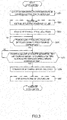
FIG. 2 is a flowchart illustrating a procedure of an activation control of the fuel cell system according to the embodiment. -
FIG. 3 is a flowchart illustrating a procedure of a stop control of the fuel cell system according to the embodiment. -
FIG. 4 is a flowchart illustrating a procedure of a low speed charge control of the fuel cell system according to the embodiment. -
FIG. 5 is a flowchart illustrating a procedure of a rapid charge control of the fuel cell system according to the embodiment. -
FIG. 6 is a flowchart illustrating a procedure of an external device coupling control in a usual electric generation of the fuel cell system according to the embodiment. -
FIG. 7 is a flowchart illustrating a procedure of the external device coupling control in a vehicle stop of the fuel cell system according to the embodiment. - The following describes embodiments of the present invention with reference to drawings.
-
FIG. 1 is a block diagram illustrating a main configuration of afuel cell system 10 according to the embodiment. Thefuel cell system 10 according to the 16-00128 / PCT-2028_[PCT] Originally filed Description, Claims, and Abstract embodiment is entirely controlled by acontrol unit 84. Thefuel cell system 10 is configured such that, for example, a fuel cell stack 52 (a fuel cell) is coupled to an electric power supply line 12 (for example, 360V), which couples amotor driving battery 14 to a drive motor 26 (a motor driving inverter 24), via acoupling line 50. Thefuel cell system 10 is configured such that, for example, a fuel cellauxiliary machine 80 is coupled to a low-voltage line 72 (for example, 12V), which couples a DC-DC converter 30 (a first voltage converter) coupled to the electricpower supply line 12 to anauxiliary machine battery 74. Furthermore, thefuel cell system 10 is configured such that a DC-DC converter 82 (a second voltage converter) couples thecoupling line 50 to the low-voltage line 72. - The
motor driving battery 14, the motor driving inverter 24 (the drive motor 26), the DC-DC converter 30, a lowspeed charging terminal 32, arapid charging terminal 36, anexternal coupling terminal 40, anIR sensor 46, and anair conditioner inverter 48 are coupled to the electricpower supply line 12. - A DC-DC converter 56 (the fuel cell stack 52), a DC-DC converter 58 (a
compressor 60 and a compressor battery 62), aswitch 66A (a changeover switch), aswitch 66B, acharging circuit 68 constituted of a series circuit of aresistive element 70 and aswitch 66C, and the DC-DC converter 82 are coupled to thecoupling line 50. - The DC-
DC converter 30, theauxiliary machine battery 74, a vehicularauxiliary machine 78, the fuel cellauxiliary machine 80, and the DC-DC converter 82 are coupled to the low-voltage line 72. - The
motor driving battery 14 includes a main power supply 16 (for example, 360V) coupled to the electricpower supply line 12, aswitch 22C coupled to a side of the positive pole of themain power supply 16, and aswitch 22D coupled to a side of the negative pole of themain power supply 16. Theswitch 22C has one side coupled to the positive pole side of the main power 16-00128 / PCT-2028_[PCT] Originally filed Description, Claims, andAbstract supply 16 and the other side coupled to a side of the positive pole of the electricpower supply line 12. Theswitch 22D has one side coupled to the negative pole side of themain power supply 16 and the other side coupled to a side of the negative pole of the electricpower supply line 12. In the positive pole side of themain power supply 16, acharging circuit 18A as a series circuit of aresistive element 20A and aswitch 22A is coupled in parallel to theswitch 22C. Furthermore, acharging circuit 18B as a series circuit of aresistive element 20B and a switch 22B is coupled to a side of the electricpower supply line 12 of theswitch 22C and the electricpower supply line 12 side of theswitch 22D. Thecharging circuits motor driving battery 14 is coupled to the electricpower supply line 12 to charge an electric charge to, for example, a capacitor inside themotor driving inverter 24 and avoids a damage to, for example, themotor driving battery 14 and themotor driving inverter 24 by avoiding an inrush current at coupling. - The
motor driving inverter 24 is coupled to the electric power supply line 12 (the positive pole side and the negative pole side), converts electric power (a DC voltage) supplied from themotor driving battery 14 or thefuel cell stack 52 into three-phase AC power, and supplies this to thedrive motor 26 to rotate thedrive motor 26. The motor driving inverter 24 converts regenerative electric power generated by thedrive motor 26 at braking of a vehicle into electric power of DC voltage to supply the electric power of DC voltage to themotor driving battery 14. - When the
fuel cell system 10 is stopped, themotor driving battery 14 is cut off from the electricpower supply line 12. At this time, the capacitor included in themotor driving inverter 24 remains storing the electric charge; therefore, the electricpower supply line 12 maintains a high voltage even after the cutoff. However, it is necessary to decrease the voltage of the electricpower supply line 12 to equal to or less than a predetermined voltage (for 16-00128 / PCT-2028_[PCT] Originally filed Description, Claims, and Abstract example, 60V) in order to prevent an electric leakage. Therefore, themotor driving inverter 24 includes adischarge circuit 28 to discharge the electric charge stored in the capacitor in order to step down the voltage of the electricpower supply line 12. - The DC-DC converter 30 (a first voltage conversion circuit) is coupled to the electric
power supply line 12 and steps down the DC voltage of the electricpower supply line 12 to supply the electric power of the low DC voltage to the low-voltage line 72. - The low
speed charging terminal 32 is coupled to an external AC power supply of an AC voltage, such as a household power source, to charge themotor driving battery 14. The lowspeed charging terminal 32 is coupled to the electricpower supply line 12 via acharger 34, which converts the AC voltage into a DC voltage applied to the electricpower supply line 12. The lowspeed charging terminal 32 includes a limit switch (not illustrated) to output a detection signal to thecontrol unit 84 as soon as the lowspeed charging terminal 32 is coupled to the external AC power supply. - The
rapid charging terminal 36 is coupled to an external DC power supply in, for example, a service station built similarly to a gas station to supply a DC voltage to output this DC voltage to the electricpower supply line 12 to rapidly charge themotor driving battery 14. Therapid charging terminal 36 is coupled to the electricpower supply line 12 viaswitches rapid charging terminal 36 also includes a limit switch (not illustrated) to output a detection signal to thecontrol unit 84 as soon as therapid charging terminal 36 is coupled to the external DC power supply. - The
external coupling terminal 40 is coupled to an external device, such as household equipment, and drives the external device with the electric power from themotor driving battery 14 or thefuel cell stack 52. Theexternal coupling terminal 40 is coupled to the electricpower supply line 12 via an 16-00128 / PCT-2028_[PCT] Originally filed Description, Claims, and Abstractexternal coupling inverter 42 and switches 44A and 44B. It should be noted that theexternal coupling terminal 40 also includes a limit switch (not illustrated) such that the limit switch outputs a detection signal to thecontrol unit 84 as soon as theexternal coupling terminal 40 is coupled to the external device. - The
IR sensor 46 is coupled to the negative pole side of the electricpower supply line 12 and a vehicular body (not illustrated), applies a constant voltage between both the sides, and measures a stray capacitance between both the sides. An insulation resistance of the electricpower supply line 12 to the body is measured from this stray capacitance, and it can be determined whether an electric leakage of the electric power supply line 21 is present or absent from the magnitude of the insulation resistance. - Additionally, for example, the air conditioner inverter 48 for an air conditioner in the vehicle is coupled to the electric
power supply line 12. - The
fuel cell stack 52 is a solid oxide fuel cell (SOFC). Thefuel cell stack 52 is provided by stacking cells obtained by an electrolyte layer made of a solid oxide, such as ceramic, being sandwiched between an anode (a fuel pole) to which a fuel gas reformed by a reformer is supplied and a cathode (an air pole) to which an air containing oxygen as an oxidizing gas is supplied. Thefuel cell stack 52 is coupled to thecoupling line 50 via the DC-DC converter 56. It should be noted that thefuel cell stack 52 includes atemperature sensor 54 that measures a temperature inside thefuel cell stack 52. - The DC-
DC converter 56 has an input side coupled to thefuel cell stack 52 and an output side (a step up side) coupled to thecoupling line 50. The DC-DC converter 56 steps up the output voltage (for example, 60V or a voltage equal to or less than it) of thefuel cell stack 52 to a voltage of the electricpower supply line 12 and supplies the voltage to thecoupling line 50. 16-00128 / PCT-2028_[PCT] Originally filed Description, Claims, and Abstract This supplies the electric power from thefuel cell stack 52 to themotor driving battery 14 or the drive motor 26 (the motor driving inverter 24) via thecoupling line 50 and the electricpower supply line 12. - The DC-
DC converter 58 has an input side coupled to thecoupling line 50 and an output side (for example, 42V) coupled to thecompressor 60. Thecompressor 60 and thecompressor battery 62 are coupled in parallel to a step down side of the DC-DC converter 58. Thecompressor 60 supplies, for example, the oxidizing gas (an air) to thefuel cell stack 52. It should be noted that acharge checker 64, which measures the amount of charge, is coupled to thecompressor battery 62. - The
switch 66A (the changeover switch) is disposed in a side of the positive pole of thecoupling line 50. Theswitch 66A has one side coupled to the positive pole side of the electricpower supply line 12 and the other side coupled to, for example, the DC-DC converter 56. Similarly, theswitch 66B is disposed in a side of the negative pole of thecoupling line 50. Theswitch 66B has one side coupled to the negative pole side of the electricpower supply line 12 and the other side coupled to, for example, the DC-DC converter 56. Theswitch 66A and theswitch 66B switch a cutoff (OFF) and a coupling (ON) of thecoupling line 50. In the positive pole side of thecoupling line 50, the chargingcircuit 68 as a series circuit of theresistive element 70 and theswitch 66C is coupled in parallel to theswitch 66A. The chargingcircuit 68 is temporarily used when themotor driving battery 14 is coupled to, for example, the DC-DC converter 56 to charge an electric charge to the capacitor that belongs to, for example, the DC-DC converter 56 and avoids a damage to, for example, themotor driving battery 14 and the DC-DC converter 56 by avoiding an inrush current at coupling. - The
auxiliary machine battery 74 is a battery having an output voltage lower than that of themotor driving battery 14. The auxiliary 16-00128 / PCT-2028_[PCT] Originally filed Description, Claims, andAbstract machine battery 74 is charged by an electric power supply from the DC-DC converter 30 (the first voltage converter) and the DC-DC converter 82 (the second voltage converter) and supplies the electric power to the vehicularauxiliary machine 78 and the fuel cellauxiliary machine 80. Acharge checker 76, which measures the amount of charge, is coupled to theauxiliary machine battery 74. - The vehicular
auxiliary machine 78 is, for example, a vehicular illumination and a car navigation system and is equipment operated with electric power with a lower voltage range and a lower-current (low electric power) than that of thedrive motor 26. - The fuel cell
auxiliary machine 80 includes, for example, a fuel supply unit (a pump and an injector) that supplies the fuel to thefuel cell stack 52. The fuel cellauxiliary machine 80 includes, for example, a valve (not illustrated) that opens and closes a passage through which the fuel gas and the oxidizing gas are distributed, a diffusion combustor (not illustrated) that generates a combustion gas for heating supplied to thefuel cell stack 52 during the activation control, and a circuit (not illustrated) that applies a reverse bias for an anode pole protection to thefuel cell stack 52 during the stop control. The fuel cellauxiliary machine 80 is equipment operated with the low electric power as is the case with the above description. - In the activation control of the
fuel cell stack 52, a combustion gas, which is made by mixing and combusting a fuel for activation and an air, is generated using, for example, the diffusion combustor. This is supplied to thefuel cell stack 52 instead of the oxidizing gas and thefuel cell stack 52 is heated up to a temperature required for an electric generation. - In the stop control of the
fuel cell stack 52, the oxidizing gas is continuously supplied as a cooling gas to decrease the temperature down to a temperature at which an oxidation of an anode is avoidable, and then the fuel 16-00128 / PCT-2028_[PCT] Originally filed Description, Claims, and Abstract cellauxiliary machine 80 and thecompressor 60 are stopped. At that time, a control to close a valve in a passage of an anode off-gas after use to prevent the oxygen from flowing backward and a control to apply an electromotive force that opposes a polarity of thefuel cell stack 52 to thefuel cell stack 52 are performed in order to prevent the oxidation of the anode. Another stop control includes a method in which the flow rate of the fuel gas is decreased but the amount of power generation with which thecompressor 60 and the fuel cellauxiliary machine 80 are barely drivable is maintained, and the temperature of thefuel cell stack 52 is decreased. Accordingly, thecompressor 60 and the fuel cellauxiliary machine 80 are used not only in the activation control but also in the stop control of thefuel cell stack 52; therefore, the electric power for them is required. - The DC-DC converter 82 (the second voltage conversion circuit) has an input side coupled to the
coupling line 50 and an output side (the step down side) coupled to the low-voltage line 72. The DC-DC converter 82 steps down the voltage of thecoupling line 50 to supply the electric power to the low-voltage line 72. The DC-DC converter 82 is coupled to a side of thefuel cell stack 52 with respect to theswitches circuit 68 in thecoupling line 50. This ensures the DC-DC converter 82 supplying the electric power from thefuel cell stack 52 to the low-voltage line 72 even though theswitches coupling line 50. It should be noted that, although the illustration is omitted, sides of thecoupling line 50 of the DC-DC converter 56, the DC-DC converter 58, and the DC-DC converter 82 also include discharge circuits (not illustrated). - The
control unit 84 is constituted of general-purpose electronic circuits and peripheral devices including a microcomputer, a microprocessor, and a CPU and executes specific programs to execute processes in order to control thefuel cell system 10. At that time, thecontrol unit 84 can perform 16-00128 / PCT-2028_[PCT] Originally filed Description, Claims, and Abstract ON/OFF controls that drive/stop the above-described respective components. - An activation control procedure of the
fuel cell system 10 according to the embodiment will be described in accordance with a flowchart inFIG. 2 . In an initial state, all theswitches 22A to 22D, 38A, 38B, 44A, 44B, and 66A to 66C are OFF, and the electricpower supply line 12 and thecoupling line 50 are stepped down to equal to or less than a predetermined voltage (for example, 60V). It is also assumed that themotor driving battery 14, theauxiliary machine battery 74, and thecompressor battery 62 have reached respective predetermined amounts of charge. - As soon as the system starts the activation control, the
control unit 84 turns the fuel cellauxiliary machine 80 and thecompressor 60 ON to start the activation control for thefuel cell stack 52 at Step S101. At that time, the fuel cellauxiliary machine 80 is driven by the electric power from theauxiliary machine battery 74, and thecompressor 60 is driven by the electric power from thecompressor battery 62. This causes the activation control of thefuel cell stack 52 to be performed for thefuel cell stack 52 until reaching a temperature required for an electric generation. - At Step S102, the
control unit 84 turns theswitch 22A and theswitch 22D ON to couple themotor driving battery 14 to the electricpower supply line 12 via the chargingcircuits power supply line 12, themotor driving inverter 24, the DC-DC converter 30, and theair conditioner inverter 48. At this time, thecontrol unit 84 also turns the switch 22B ON to apply the voltage to the chargingcircuit 18B coupled in parallel to the electricpower supply line 12. After a predetermined time at Step S102, thecontrol unit 84 turns theswitch 22C ON and then turns theswitch 22A OFF to cut off the chargingcircuit 18A so as to directly couple themotor driving battery 14 to 16-00128 / PCT-2028_[PCT] Originally filed Description, Claims, and Abstract the electricpower supply line 12 at Step S103. At this time, thecontrol unit 84 also turns the switch 22B OFF to cut off the chargingcircuit 18B. This ensures a rotation of thedrive motor 26 at any rotation speed on the basis of an accelerator operation of a driver. - At Step S104, the
control unit 84 turns the DC-DC converter 30 ON to apply a predetermined voltage (for example, 12V) to the low-voltage line 72. This ensures the vehicularauxiliary machine 78 and the fuel cellauxiliary machine 80 receiving the electric power supply from theauxiliary machine battery 74 and the DC-DC converter 30 to be driven. At this time, theauxiliary machine battery 74 is charged with the DC-DC converter 30. At this time, thecontrol unit 84 turns theair conditioner inverter 48 ON to cause the air conditioner for a vehicle interior to be in a usable state. - At Step S105, the
control unit 84 turns theswitch 66B and theswitch 66C ON to apply a predetermined voltage to the coupling line 50 (for example, the DC-DC converter 56) via the chargingcircuit 68. Then, after a predetermined time at Step S105, thecontrol unit 84 turns theswitch 66A ON and then turns theswitch 66C OFF to cut off the chargingcircuit 68 so as to directly couple the electricpower supply line 12 to the coupling line 50 (for example, the DC-DC converter 56) at Step S106. - At Step S107, the
control unit 84 determines whether thefuel cell stack 52 has reached an operating temperature required for the electric generation or not from a temperature measured by thetemperature sensor 54. After thefuel cell stack 52 reaches the operating temperature, thecontrol unit 84 terminates the activation control for thefuel cell stack 52 and supplies the fuel gas (the reformed gas) and the oxidizing gas to thefuel cell stack 52 to generate the electric power by electrochemical reaction at Step S108. - At Step S109, the
control unit 84 turns the DC-DC converter 56, the DC-DC converter 58, and the DC-DC converter 82 ON. This causes the fuel 16-00128 / PCT-2028_[PCT] Originally filed Description, Claims, andAbstract cell stack 52 to supply the generated electric power to the electricpower supply line 12 via the DC-DC converter 56 and to the low-voltage line 72 via the DC-DC converter 56 and the DC-DC converter 82. Thefuel cell stack 52 supplies the generated electric power to thecompressor 60 and thecompressor battery 62 via the DC-DC converter 56 and the DC-DC converter 58. The activation control of thefuel cell system 10 is thus terminated. - The
drive motor 26 receives the electric power supply from themotor driving battery 14 and thefuel cell stack 52 and rotates at any rotation speed by the accelerator operation of the driver. Thedrive motor 26 generates the regenerative electric power at braking and this is charged to themotor driving battery 14 via themotor driving inverter 24. Themotor driving battery 14 is charged by the electric power supply from thefuel cell stack 52 as soon as the amount of charge is equal to or less than a certain amount of charge. Theauxiliary machine battery 74 is charged by the electric power supply from the DC-DC converter 30 and the DC-DC converter 82 and supplies the electric power to the vehicularauxiliary machine 78 and the fuel cellauxiliary machine 80. Furthermore, the vehicularauxiliary machine 78 and the fuel cellauxiliary machine 80 can be driven by the electric power supply from the DC-DC converter 30, the DC-DC converter 82, and theauxiliary machine battery 74. Thecompressor 60 receives the electric power supply from thecompressor battery 62 and the DC-DC converter 58 to be driven, and thecompressor battery 62 is charged by receiving the electric power supply from the DC-DC converter 58. Thus, in the usual electric generation, thecontrol unit 84 cooperatively controls the DC-DC converter 30 and the DC-DC converter 82. This supplies the electric power to the aforementioned fuel supply unit (the pump and the injector) from thefuel cell stack 52 in a condition where the electric power is supplied from the motor driving battery 16-00128 / PCT-2028_[PCT] Originally filed Description, Claims, andAbstract 14 and thefuel cell stack 52 is operating; therefore, the supply of the fuel to thefuel cell stack 52 can be maintained while reducing a load of the DC-DC converter 30. - A stop control procedure of the
fuel cell system 10 according to the embodiment will be described in accordance with a flowchart illustrated inFIG. 3 . At Step S201, thecontrol unit 84 turns theswitch 22C and theswitch 22D OFF to cut off themotor driving battery 14 from the electricpower supply line 12 and turns theswitch 66A and theswitch 66B OFF to cut off thecoupling line 50 from the electricpower supply line 12. This stops the electric power supply to themotor driving inverter 24 and the DC-DC converter 30. Simultaneously with this, themotor driving inverter 24, the DC-DC converter 30, and theair conditioner inverter 48 are turned OFF. At this time, while the electric power supply from the DC-DC converter 30 is stopped in the low-voltage line 72, the electric power supply from thefuel cell stack 52 is maintained via the DC-DC converter 82. - At Step S202, the
control unit 84 turns thedischarge circuit 28 ON to step down the voltage of the electricpower supply line 12 to equal to or less than a predetermined voltage (for example, 60V), and then turns thedischarge circuit 28 OFF. At that time, since theswitch 66A and theswitch 66B are already turned OFF, the electric charge held by the DC-DC converter 56, the DC-DC converter 58, and the DC-DC converter 82 does not flow into thedischarge circuit 28. - At Step S203, the
control unit 84 performs the stop control for thefuel cell stack 52. The stop control includes a case where the fuel gas supply is stopped to stop the electric generation of thefuel cell stack 52 so as to cool thefuel cell stack 52 as described above and a case where thefuel cell stack 52 is cooled while the fuel gas supply is minimized to generate the electric power 16-00128 / PCT-2028_[PCT] Originally filed Description, Claims, and Abstract barely enough for thefuel cell stack 52 to drive thecompressor 60 and the fuel cellauxiliary machine 80, and further, barely enough to ensure charging theauxiliary machine battery 74. When thefuel cell stack 52 continues to generate the electric power, the electric power generated by thefuel cell stack 52 is continuously supplied to thecompressor 60 via the DC-DC converter 58 and supplied to the fuel cellauxiliary machine 80 via the DC-DC converter 82 to be further supplied to theauxiliary machine battery 74 as well. - At Step S204, the
control unit 84 determines whether a temperature of thefuel cell stack 52 has decreased down to the predetermined temperature at which the anode is not oxidized or not from the temperature measured by thetemperature sensor 54. At Step S205, thecontrol unit 84 determines whether the amount of charge of theauxiliary machine battery 74 measured by thecharge checker 76 and the amount of charge of thecompressor battery 62 measured by thecharge checker 64 have reached respective predetermined amounts or not. - At Step S206, the
control unit 84 turns the fuel cellauxiliary machine 80 and thecompressor 60 OFF on condition that thefuel cell stack 52 has decreased down to the predetermined temperature and theauxiliary machine battery 74 and thecompressor battery 62 have reached the predetermined amounts of charge, and terminates the stop control of thefuel cell stack 52. - At Step S207, the
control unit 84 turns the DC-DC converter 56, the DC-DC converter 58, and the DC-DC converter 82 OFF and turns their discharge circuits (not illustrated) ON to step down thecoupling line 50 to equal to or less than a predetermined voltage (for example, 60V), and then turns the discharge circuits OFF. The stop control of thefuel cell system 10 is thus terminated. It should be noted that Step S202 and Step S203 may be in reverse order or may be performed simultaneously. 16-00128 / PCT-2028_[PCT] Originally filed Description, Claims, and Abstract - A low speed charge control procedure of the
fuel cell system 10 according to the embodiment will be described in accordance with a flowchart illustrated inFIG. 4 . An initial state is similar to the initial state in the aforementioned activation control. At Step S301, as soon as the lowspeed charging terminal 32 is coupled to the external AC power supply, the limit switch (not illustrated) outputs the detection signal to thecontrol unit 84. At Step S302, thecontrol unit 84 turns thecharger 34, theswitch 22C, and theswitch 22D ON as soon as the detection signal is input. This steps up the electricpower supply line 12 to a predetermined voltage (for example, 360V) and themotor driving battery 14 is charged by the electric power supply of the external AC power supply. At this time, thecontrol unit 84 may turn the DC-DC converter 30 ON to charge theauxiliary machine battery 74. - At Step S303, when the detection signal is stopped, that is, the low
speed charging terminal 32 is cut off from the external AC power supply, thecontrol unit 84 turns thecharger 34, theswitch 22C, and theswitch 22D OFF at Step S304. At Step S305, thecontrol unit 84 turns thedischarge circuit 28 ON to decrease the electricpower supply line 12 down to equal to or less than a predetermined voltage (for example, 60V) and then, turns thedischarge circuit 28 OFF. - A rapid charge control procedure of the
fuel cell system 10 according to the embodiment will be described in accordance with a flowchart illustrated inFIG. 5 . An initial state is similar to the initial state at the aforementioned activation control. At Step S401, as soon as therapid charging terminal 36 is coupled to the external DC power supply, the limit switch (not illustrated) outputs the detection signal to thecontrol unit 84. At Step S402, thecontrol unit 84 turns theIR sensor 46 ON to start measuring a value of an insulation 16-00128 / PCT-2028_[PCT] Originally filed Description, Claims, and Abstract resistance between the electricpower supply line 12 and the body (not illustrated) as soon as the detection signal is input. - At Step S403, the
control unit 84 determines whether the aforementioned insulation resistance is equal to or more than a predetermined value or not. At Step S404, thecontrol unit 84 turns theswitches switches rapid charging terminal 36 to the electricpower supply line 12 to step up the electricpower supply line 12 to a predetermined voltage (for example, 360V) and the motor driving battery 14 (and, for example, the motor driving inverter 24) is rapidly charged with the external DC power supply. At this time, thecontrol unit 84 may turn the DC-DC converter 30 ON to charge theauxiliary machine battery 74. Thecontrol unit 84 turns theIR sensor 46 OFF to terminate the measurement of the value of the aforementioned insulation resistance. - At Step S405, when the detection signal is stopped, that is, the
rapid charging terminal 36 is cut off from the external DC power supply, thecontrol unit 84 turns theswitches switches motor driving battery 14 and therapid charging terminal 36 from the electricpower supply line 12 at Step S406. At Step S407, thecontrol unit 84 turns thedischarge circuit 28 ON to decrease the electricpower supply line 12 down to equal to or less than a predetermined voltage (for example, 60V) and then, turns thedischarge circuit 28 OFF. - An external device coupling control procedure of the
fuel cell system 10 according to the embodiment in the usual electric generation will be described in accordance with a flowchart illustrated inFIG. 6 . At Step S501, as soon as 16-00128 / PCT-2028_[PCT] Originally filed Description, Claims, and Abstract theexternal coupling terminal 40 is coupled to an external device, the limit switch (not illustrated) outputs a detection signal to thecontrol unit 84. At Step S502, thecontrol unit 84 turns theexternal coupling inverter 42 and theswitches external coupling terminal 40 to the electricpower supply line 12. This ensures driving the external device with the electric power from themotor driving battery 14 or thefuel cell stack 52. - At Step S503, when the detection signal is stopped, that is, the
external coupling terminal 40 is cut off from the external device, thecontrol unit 84 turns theexternal coupling inverter 42 and theswitches external coupling terminal 40 from the electricpower supply line 12 at Step S504. It should be noted that the above-described procedure is possible in the low speed charging and the rapid charging. In the low speed charging, the external device can be driven with the electric power from themotor driving battery 14 or the external AC power supply. In the rapid charging, the external device can be driven with the electric power from themotor driving battery 14 or the external DC power supply. - An external device coupling control procedure of the
fuel cell system 10 according to the embodiment in a vehicle stop will be described in accordance with a flowchart illustrated inFIG. 7 . At Step S601, as soon as theexternal coupling terminal 40 is coupled to an external device, the limit switch (not illustrated) outputs a detection signal to thecontrol unit 84. At Step S602, thecontrol unit 84 turns theswitch 22A and theswitch 22D ON to couple themotor driving battery 14 to the electricpower supply line 12 via the chargingcircuit 18A and applies a predetermined voltage (for example, 360V) to the electric power supply line 12 (and, for example, the motor driving inverter 24). At this time, thecontrol unit 84 also turns the switch 22B ON to electrically 16-00128 / PCT-2028_[PCT] Originally filed Description, Claims, and Abstract conduct the chargingcircuit 18B. After a predetermined time at Step S602, thecontrol unit 84 turns theswitch 22C ON and then turns theswitch 22A OFF to cut off the chargingcircuit 18A so as to directly couples themotor driving battery 14 to the electricpower supply line 12 as Step S603. At this time, thecontrol unit 84 also turns the switch 22B OFF to cut off the chargingcircuit 18B. - At Step S604, the
control unit 84 turns theexternal coupling inverter 42 and theswitches external coupling terminal 40 to the electricpower supply line 12. This ensures driving the external device with the electric power from themotor driving battery 14. At Step S605, when the detection signal is stopped, that is, theexternal coupling terminal 40 is cut off from the external device, thecontrol unit 84 turns theexternal coupling inverter 42, theswitches switches motor driving battery 14 and theexternal coupling terminal 40 from the electricpower supply line 12 at Step S606. At Step S607, thecontrol unit 84 turns thedischarge circuit 28 ON to step down the electricpower supply line 12 to equal to or less than a predetermined voltage (for example, 60V) and then turns thedischarge circuit 28 OFF. - With the
fuel cell system 10 according to the embodiment, the fuel cellauxiliary machine 80 is coupled to the DC-DC converter 30 (the first voltage converter) supplying the electric power to the vehicularauxiliary machine 78 and the DC-DC converter 82 (the second voltage converter) coupled to thefuel cell stack 52 so as to be configured to receive the electric power supply from each of them. Accordingly, a load of the DC-DC converter 30 can be reduced, thereby ensuring a design with a decreased electric power capacity of the DC-DC converter 30. - The stop control of the
fuel cell stack 52 includes a case where the 16-00128 / PCT-2028_[PCT] Originally filed Description, Claims, and Abstractfuel cell stack 52 is cooled while the fuel gas supply is minimized such that thefuel cell stack 52 generates electric power barely enough to drive thecompressor 60 and the fuel cellauxiliary machine 80. Even in such a case, the electric power can be supplied to the fuel cellauxiliary machine 80 via the DC-DC converters compressor 60 via the DC-DC converters fuel cell stack 52. - The fuel cell
auxiliary machine 80 can receive the electric power supply also from theauxiliary machine battery 74, which supplies the electric power to the vehicularauxiliary machine 78. However, theauxiliary machine battery 74 is also coupled to the DC-DC converter 30 (the first voltage converter) and the DC-DC converter 82 (the second voltage converter) so as to be configured to receive the electric power supply from each of them. Accordingly, charging of theauxiliary machine battery 74 can be easily covered. - The
control unit 84 performs the control to stop the driving of the fuel cellauxiliary machine 80 when theauxiliary machine battery 74 charged via the DC-DC converter 82 (the second voltage converter) in the stop control of thefuel cell stack 52 reaches the predetermined amount of charge. This ensures the amount of charge of theauxiliary machine battery 74 for operating the vehicularauxiliary machine 78 and the fuel cellauxiliary machine 80 with certainty in the next activation. - The
control unit 84 performs the control to cut off thecoupling line 50 to theswitches 66A (the changeover switch) and 66B when themotor driving battery 14 is cut off from the electricpower supply line 12. This avoids the electric charge carried by the DC-DC converter 56, the DC-DC converter 58, and the DC-DC converter 82 (the electric charge carried by the coupling line 50) from flowing into the motor driving inverter 24 (the drive motor 26), thereby 16-00128 / PCT-2028_[PCT] Originally filed Description, Claims, and Abstract ensuring avoiding the excessive current from damaging thedischarge circuit 28 coupled to themotor driving inverter 24. - Even after the cutoff of the
motor driving battery 14, the coupling from thefuel cell stack 52 to the DC-DC converter 82 and the coupling from thefuel cell stack 52 to the DC-DC converter 58 are maintained. Accordingly, even after the cutoff of themotor driving battery 14, the electric power can be supplied from thefuel cell stack 52 to the fuel cellauxiliary machine 80 and thecompressor 60, and even if the electric power of theauxiliary machine battery 74 is depleted, the self-sustained operation of thefuel cell stack 52 is possible. Furthermore, when thefuel cell stack 52 not only supplies the electric power to the fuel cellauxiliary machine 80 and thecompressor 60 but also generates the electric power barely enough to charge theauxiliary machine battery 74 during the stop control, the electric power for the fuel cellauxiliary machine 80 can be covered by theauxiliary machine battery 74, thereby ensuring covering the electric power required for the next stop process with certainty without relying on thecompressor battery 62. - The
control unit 84 performs the control to electrically conduct the chargingcircuit 68 when themotor driving battery 14 is coupled to the electricpower supply line 12, and after the predetermined time, electrically conduct theswitch 66A (the changeover switch). This avoids the inrush current to thecoupling line 50, thereby ensuring preventing the damage to the components, such as the DC-DC converter 56 coupled to thecoupling line 50 and themotor driving battery 14. - The embodiment of the present invention described above are merely illustration of a part of application examples of the present invention and not of the nature to limit the technical scope of the present invention to the specific constructions of the above embodiments.
- This application claims priority based on Patent Application No. 16-00128 / PCT-2028_[PCT] Originally filed Description, Claims, and Abstract
2015-243837
Claims (5)
- A fuel cell system in which a fuel cell is coupled to a motor driving battery and a vehicular auxiliary machine is coupled to the motor driving battery via a first voltage converter, the fuel cell system comprising:a fuel cell auxiliary machine coupled to the first voltage converter; anda second voltage converter that couples the fuel cell auxiliary machine to the fuel cell.
- The fuel cell system according to claim 1, further comprising
an auxiliary machine battery coupled to the first voltage converter, the auxiliary machine battery having a voltage lower than a voltage of the motor driving battery, wherein
the fuel cell auxiliary machine and the second voltage converter are coupled to the auxiliary machine battery. - The fuel cell system according to claim 2, wherein
the fuel cell system continues an electric generation of the fuel cell until the auxiliary machine battery reaches a predetermined amount of charge in a stop control of the fuel cell system. - The fuel cell system according to any one of claims 1 to 3, wherein
the fuel cell auxiliary machine is a fuel supply unit configured to supply a fuel to the fuel cell. - The fuel cell system according to any one of claims 1 to 4, wherein
the fuel cell is coupled to an electric power supply line coupling the motor driving battery to a drive motor, 16-00128 / PCT-2028_[PCT] Originally filed Description, Claims, and Abstract
the fuel cell system further includes:a changeover switch configured to switch a cutoff and an electrical conduct of a coupling line coupling the fuel cell to the electric power supply line; anda control unit configured to control the changeover switch,the second voltage converter is coupled to a side of the fuel cell with respect to the changeover switch in the coupling line, and
the control unit is configured such that a control to cut off the coupling line is performed on the changeover switch when a control to cut off the motor driving battery from the electric power supply line is performed.
Applications Claiming Priority (2)
| Application Number | Priority Date | Filing Date | Title |
|---|---|---|---|
| JP2015243837 | 2015-12-15 | ||
| PCT/JP2016/081132 WO2017104256A1 (en) | 2015-12-15 | 2016-10-20 | Fuel cell system |
Publications (3)
| Publication Number | Publication Date |
|---|---|
| EP3392942A1 true EP3392942A1 (en) | 2018-10-24 |
| EP3392942A4 EP3392942A4 (en) | 2018-12-05 |
| EP3392942B1 EP3392942B1 (en) | 2022-09-21 |
Family
ID=59056028
Family Applications (1)
| Application Number | Title | Priority Date | Filing Date |
|---|---|---|---|
| EP16875241.8A Active EP3392942B1 (en) | 2015-12-15 | 2016-10-20 | Fuel cell system |
Country Status (7)
| Country | Link |
|---|---|
| US (1) | US11465505B2 (en) |
| EP (1) | EP3392942B1 (en) |
| JP (1) | JP6508360B2 (en) |
| CN (1) | CN108432012B (en) |
| BR (1) | BR112018011983B1 (en) |
| CA (1) | CA3008117C (en) |
| WO (1) | WO2017104256A1 (en) |
Cited By (2)
| Publication number | Priority date | Publication date | Assignee | Title |
|---|---|---|---|---|
| WO2021059235A1 (en) * | 2019-09-26 | 2021-04-01 | Ceres Intellectual Property Company Limited | Car power supply system and solid oxide fuel cell vehicle |
| CN114946058A (en) * | 2020-01-17 | 2022-08-26 | 松下知识产权经营株式会社 | Fuel cell system and control method of fuel cell system |
Families Citing this family (10)
| Publication number | Priority date | Publication date | Assignee | Title |
|---|---|---|---|---|
| DE102017213306A1 (en) * | 2017-08-01 | 2019-02-07 | Siemens Aktiengesellschaft | Energy supply device for a rail vehicle |
| JP7230635B2 (en) * | 2019-03-27 | 2023-03-01 | トヨタ自動車株式会社 | Electric power system and its control method |
| DE102019214240B3 (en) * | 2019-09-18 | 2020-12-31 | Vitesco Technologies GmbH | Configurable DC / DC converter circuit and vehicle electrical system |
| CN114555405B (en) * | 2019-10-15 | 2025-05-06 | 纬湃科技有限责任公司 | Vehicle electrical system |
| JP7205451B2 (en) * | 2019-12-04 | 2023-01-17 | トヨタ自動車株式会社 | Vehicles and vehicle control methods |
| KR20230020165A (en) * | 2021-08-03 | 2023-02-10 | 현대자동차주식회사 | Mobile electric vehicle charging system |
| WO2023204217A1 (en) * | 2022-04-18 | 2023-10-26 | ビークルエナジージャパン株式会社 | Power supply control device |
| DE102022211846A1 (en) * | 2022-11-09 | 2024-05-16 | Zf Friedrichshafen Ag | Method and device for operating an electrical system for a vehicle, electrical system for a vehicle and vehicle |
| DE102022211845A1 (en) * | 2022-11-09 | 2024-05-16 | Zf Friedrichshafen Ag | Electrical device for a vehicle and vehicle with electrical device |
| FR3154660A1 (en) * | 2023-10-26 | 2025-05-02 | Alstom Holdings | VEHICLE DRIVE SYSTEM AND CHARGING METHOD |
Family Cites Families (12)
| Publication number | Priority date | Publication date | Assignee | Title |
|---|---|---|---|---|
| DE19954306B4 (en) * | 1999-11-11 | 2004-09-02 | Ballard Power Systems Ag | Device for generating electrical energy with a fuel cell in a vehicle and method for operating such a device |
| JP4783580B2 (en) * | 2005-03-31 | 2011-09-28 | 本田技研工業株式会社 | Fuel cell electrical system, fuel cell vehicle and power supply method |
| JP2007157477A (en) * | 2005-12-05 | 2007-06-21 | Toyota Motor Corp | Fuel cell system |
| JP2009140757A (en) * | 2007-12-06 | 2009-06-25 | Toyota Motor Corp | Fuel cell system |
| JP5440908B2 (en) * | 2009-06-04 | 2014-03-12 | 日産自動車株式会社 | Fuel cell system |
| JP5308268B2 (en) | 2009-08-05 | 2013-10-09 | 本田技研工業株式会社 | Power supply system |
| JP5754346B2 (en) * | 2011-10-31 | 2015-07-29 | 株式会社デンソー | Fuel cell system |
| WO2013099009A1 (en) * | 2011-12-28 | 2013-07-04 | トヨタ自動車株式会社 | Fuel cell system |
| JP2014068490A (en) | 2012-09-26 | 2014-04-17 | Honda Motor Co Ltd | Power supply system |
| JP2014220152A (en) * | 2013-05-09 | 2014-11-20 | 株式会社ノーリツ | Power generation device |
| DE102014224574A1 (en) * | 2014-12-02 | 2016-06-02 | Robert Bosch Gmbh | Intrinsically safe bleed-down circuit and control strategy for fuel cell systems |
| CN109562698B (en) * | 2016-07-29 | 2020-02-07 | 日产自动车株式会社 | Vehicle system |
-
2016
- 2016-10-20 BR BR112018011983-0A patent/BR112018011983B1/en not_active IP Right Cessation
- 2016-10-20 EP EP16875241.8A patent/EP3392942B1/en active Active
- 2016-10-20 CA CA3008117A patent/CA3008117C/en active Active
- 2016-10-20 CN CN201680074033.8A patent/CN108432012B/en active Active
- 2016-10-20 JP JP2017556391A patent/JP6508360B2/en active Active
- 2016-10-20 US US16/061,433 patent/US11465505B2/en active Active
- 2016-10-20 WO PCT/JP2016/081132 patent/WO2017104256A1/en not_active Ceased
Cited By (5)
| Publication number | Priority date | Publication date | Assignee | Title |
|---|---|---|---|---|
| WO2021059235A1 (en) * | 2019-09-26 | 2021-04-01 | Ceres Intellectual Property Company Limited | Car power supply system and solid oxide fuel cell vehicle |
| GB2602595A (en) * | 2019-09-26 | 2022-07-06 | Ceres Ip Co Ltd | Car power supply system and solid oxide fuel cell vehicle |
| GB2602595B (en) * | 2019-09-26 | 2023-03-22 | Ceres Ip Co Ltd | Car power supply system and solid oxide fuel cell vehicle |
| CN114946058A (en) * | 2020-01-17 | 2022-08-26 | 松下知识产权经营株式会社 | Fuel cell system and control method of fuel cell system |
| EP4092790A4 (en) * | 2020-01-17 | 2024-05-01 | Panasonic Intellectual Property Management Co., Ltd. | FUEL CELL SYSTEM AND CONTROL METHODS FOR FUEL CELL SYSTEM |
Also Published As
| Publication number | Publication date |
|---|---|
| JP6508360B2 (en) | 2019-05-15 |
| US11465505B2 (en) | 2022-10-11 |
| JPWO2017104256A1 (en) | 2018-11-08 |
| WO2017104256A1 (en) | 2017-06-22 |
| EP3392942A4 (en) | 2018-12-05 |
| EP3392942B1 (en) | 2022-09-21 |
| CA3008117C (en) | 2023-09-26 |
| CN108432012A (en) | 2018-08-21 |
| CN108432012B (en) | 2021-02-23 |
| BR112018011983A2 (en) | 2018-12-11 |
| US20200282848A1 (en) | 2020-09-10 |
| CA3008117A1 (en) | 2017-06-22 |
| BR112018011983B1 (en) | 2022-09-06 |
Similar Documents
| Publication | Publication Date | Title |
|---|---|---|
| EP3392942B1 (en) | Fuel cell system | |
| EP3392073B1 (en) | Vehicle system equipped with fuel cell, and control method for vehicle system equipped with fuel cell | |
| US10723236B2 (en) | Electrical vehicle system with converters to share power between fuel, cell, high voltage battery and low voltage battery | |
| US6781343B1 (en) | Hybrid power supply device | |
| US7436148B2 (en) | Method of determining voltage condition of fuel cell vehicle | |
| CN101909923B (en) | Fuel cell system and fuel cell vehicle | |
| US10099573B2 (en) | Drive system and vehicle | |
| US8027759B2 (en) | Fuel cell vehicle system | |
| CN101828288B (en) | Fuel cell system | |
| JP4085642B2 (en) | Fuel cell system | |
| CN101803089B (en) | Fuel cell system | |
| JP4831063B2 (en) | Fuel cell system | |
| JP5339195B2 (en) | Fuel cell system | |
| US20260131697A1 (en) | Driving control apparatus and method for electric vehicle |
Legal Events
| Date | Code | Title | Description |
|---|---|---|---|
| STAA | Information on the status of an ep patent application or granted ep patent |
Free format text: STATUS: THE INTERNATIONAL PUBLICATION HAS BEEN MADE |
|
| PUAI | Public reference made under article 153(3) epc to a published international application that has entered the european phase |
Free format text: ORIGINAL CODE: 0009012 |
|
| STAA | Information on the status of an ep patent application or granted ep patent |
Free format text: STATUS: REQUEST FOR EXAMINATION WAS MADE |
|
| 17P | Request for examination filed |
Effective date: 20180712 |
|
| AK | Designated contracting states |
Kind code of ref document: A1 Designated state(s): AL AT BE BG CH CY CZ DE DK EE ES FI FR GB GR HR HU IE IS IT LI LT LU LV MC MK MT NL NO PL PT RO RS SE SI SK SM TR |
|
| AX | Request for extension of the european patent |
Extension state: BA ME |
|
| A4 | Supplementary search report drawn up and despatched |
Effective date: 20181107 |
|
| RIC1 | Information provided on ipc code assigned before grant |
Ipc: H01M 8/04302 20160101ALI20181029BHEP Ipc: H01M 8/04225 20160101ALI20181029BHEP Ipc: H01M 8/00 20160101ALI20181029BHEP Ipc: H01M 8/12 20160101ALI20181029BHEP Ipc: H01M 8/04701 20160101ALI20181029BHEP Ipc: H01M 8/124 20160101ALN20181029BHEP Ipc: H01M 8/04828 20160101ALI20181029BHEP Ipc: H01M 8/04303 20160101ALI20181029BHEP Ipc: H01M 8/04228 20160101ALI20181029BHEP Ipc: H01M 8/04537 20160101ALI20181029BHEP Ipc: B60L 11/18 20060101ALI20181029BHEP Ipc: H01M 8/04 20160101AFI20181029BHEP Ipc: B60L 1/00 20060101ALI20181029BHEP Ipc: H01M 16/00 20060101ALI20181029BHEP |
|
| DAV | Request for validation of the european patent (deleted) | ||
| DAX | Request for extension of the european patent (deleted) | ||
| RIC1 | Information provided on ipc code assigned before grant |
Ipc: H01M 8/124 20160101ALN20220426BHEP Ipc: B60L 50/50 20190101ALI20220426BHEP Ipc: H01M 8/04828 20160101ALI20220426BHEP Ipc: H01M 8/04701 20160101ALI20220426BHEP Ipc: H01M 8/04537 20160101ALI20220426BHEP Ipc: H01M 8/04225 20160101ALI20220426BHEP Ipc: H01M 8/04302 20160101ALI20220426BHEP Ipc: H01M 16/00 20060101ALI20220426BHEP Ipc: H01M 8/12 20160101ALI20220426BHEP Ipc: H01M 8/04303 20160101ALI20220426BHEP Ipc: H01M 8/04228 20160101ALI20220426BHEP Ipc: H01M 8/00 20160101ALI20220426BHEP Ipc: H01M 8/04 20160101AFI20220426BHEP |
|
| GRAP | Despatch of communication of intention to grant a patent |
Free format text: ORIGINAL CODE: EPIDOSNIGR1 |
|
| STAA | Information on the status of an ep patent application or granted ep patent |
Free format text: STATUS: GRANT OF PATENT IS INTENDED |
|
| RIC1 | Information provided on ipc code assigned before grant |
Ipc: H01M 8/124 20160101ALN20220511BHEP Ipc: B60L 50/50 20190101ALI20220511BHEP Ipc: H01M 8/04828 20160101ALI20220511BHEP Ipc: H01M 8/04701 20160101ALI20220511BHEP Ipc: H01M 8/04537 20160101ALI20220511BHEP Ipc: H01M 8/04225 20160101ALI20220511BHEP Ipc: H01M 8/04302 20160101ALI20220511BHEP Ipc: H01M 16/00 20060101ALI20220511BHEP Ipc: H01M 8/12 20160101ALI20220511BHEP Ipc: H01M 8/04303 20160101ALI20220511BHEP Ipc: H01M 8/04228 20160101ALI20220511BHEP Ipc: H01M 8/00 20160101ALI20220511BHEP Ipc: H01M 8/04 20160101AFI20220511BHEP |
|
| INTG | Intention to grant announced |
Effective date: 20220608 |
|
| GRAS | Grant fee paid |
Free format text: ORIGINAL CODE: EPIDOSNIGR3 |
|
| GRAA | (expected) grant |
Free format text: ORIGINAL CODE: 0009210 |
|
| STAA | Information on the status of an ep patent application or granted ep patent |
Free format text: STATUS: THE PATENT HAS BEEN GRANTED |
|
| RIN1 | Information on inventor provided before grant (corrected) |
Inventor name: KUMADA, MITSUNORI Inventor name: SUZUKI, KENTA |
|
| AK | Designated contracting states |
Kind code of ref document: B1 Designated state(s): AL AT BE BG CH CY CZ DE DK EE ES FI FR GB GR HR HU IE IS IT LI LT LU LV MC MK MT NL NO PL PT RO RS SE SI SK SM TR |
|
| REG | Reference to a national code |
Ref country code: GB Ref legal event code: FG4D |
|
| REG | Reference to a national code |
Ref country code: CH Ref legal event code: EP |
|
| REG | Reference to a national code |
Ref country code: DE Ref legal event code: R096 Ref document number: 602016075201 Country of ref document: DE |
|
| REG | Reference to a national code |
Ref country code: IE Ref legal event code: FG4D |
|
| REG | Reference to a national code |
Ref country code: AT Ref legal event code: REF Ref document number: 1520410 Country of ref document: AT Kind code of ref document: T Effective date: 20221015 |
|
| REG | Reference to a national code |
Ref country code: LT Ref legal event code: MG9D |
|
| REG | Reference to a national code |
Ref country code: NL Ref legal event code: MP Effective date: 20220921 |
|
| PG25 | Lapsed in a contracting state [announced via postgrant information from national office to epo] |
Ref country code: SE Free format text: LAPSE BECAUSE OF FAILURE TO SUBMIT A TRANSLATION OF THE DESCRIPTION OR TO PAY THE FEE WITHIN THE PRESCRIBED TIME-LIMIT Effective date: 20220921 Ref country code: RS Free format text: LAPSE BECAUSE OF FAILURE TO SUBMIT A TRANSLATION OF THE DESCRIPTION OR TO PAY THE FEE WITHIN THE PRESCRIBED TIME-LIMIT Effective date: 20220921 Ref country code: NO Free format text: LAPSE BECAUSE OF FAILURE TO SUBMIT A TRANSLATION OF THE DESCRIPTION OR TO PAY THE FEE WITHIN THE PRESCRIBED TIME-LIMIT Effective date: 20221221 Ref country code: LV Free format text: LAPSE BECAUSE OF FAILURE TO SUBMIT A TRANSLATION OF THE DESCRIPTION OR TO PAY THE FEE WITHIN THE PRESCRIBED TIME-LIMIT Effective date: 20220921 Ref country code: LT Free format text: LAPSE BECAUSE OF FAILURE TO SUBMIT A TRANSLATION OF THE DESCRIPTION OR TO PAY THE FEE WITHIN THE PRESCRIBED TIME-LIMIT Effective date: 20220921 Ref country code: FI Free format text: LAPSE BECAUSE OF FAILURE TO SUBMIT A TRANSLATION OF THE DESCRIPTION OR TO PAY THE FEE WITHIN THE PRESCRIBED TIME-LIMIT Effective date: 20220921 |
|
| REG | Reference to a national code |
Ref country code: AT Ref legal event code: MK05 Ref document number: 1520410 Country of ref document: AT Kind code of ref document: T Effective date: 20220921 |
|
| PG25 | Lapsed in a contracting state [announced via postgrant information from national office to epo] |
Ref country code: HR Free format text: LAPSE BECAUSE OF FAILURE TO SUBMIT A TRANSLATION OF THE DESCRIPTION OR TO PAY THE FEE WITHIN THE PRESCRIBED TIME-LIMIT Effective date: 20220921 Ref country code: GR Free format text: LAPSE BECAUSE OF FAILURE TO SUBMIT A TRANSLATION OF THE DESCRIPTION OR TO PAY THE FEE WITHIN THE PRESCRIBED TIME-LIMIT Effective date: 20221222 |
|
| PG25 | Lapsed in a contracting state [announced via postgrant information from national office to epo] |
Ref country code: SM Free format text: LAPSE BECAUSE OF FAILURE TO SUBMIT A TRANSLATION OF THE DESCRIPTION OR TO PAY THE FEE WITHIN THE PRESCRIBED TIME-LIMIT Effective date: 20220921 Ref country code: RO Free format text: LAPSE BECAUSE OF FAILURE TO SUBMIT A TRANSLATION OF THE DESCRIPTION OR TO PAY THE FEE WITHIN THE PRESCRIBED TIME-LIMIT Effective date: 20220921 Ref country code: PT Free format text: LAPSE BECAUSE OF FAILURE TO SUBMIT A TRANSLATION OF THE DESCRIPTION OR TO PAY THE FEE WITHIN THE PRESCRIBED TIME-LIMIT Effective date: 20230123 Ref country code: ES Free format text: LAPSE BECAUSE OF FAILURE TO SUBMIT A TRANSLATION OF THE DESCRIPTION OR TO PAY THE FEE WITHIN THE PRESCRIBED TIME-LIMIT Effective date: 20220921 Ref country code: CZ Free format text: LAPSE BECAUSE OF FAILURE TO SUBMIT A TRANSLATION OF THE DESCRIPTION OR TO PAY THE FEE WITHIN THE PRESCRIBED TIME-LIMIT Effective date: 20220921 Ref country code: AT Free format text: LAPSE BECAUSE OF FAILURE TO SUBMIT A TRANSLATION OF THE DESCRIPTION OR TO PAY THE FEE WITHIN THE PRESCRIBED TIME-LIMIT Effective date: 20220921 |
|
| PG25 | Lapsed in a contracting state [announced via postgrant information from national office to epo] |
Ref country code: SK Free format text: LAPSE BECAUSE OF FAILURE TO SUBMIT A TRANSLATION OF THE DESCRIPTION OR TO PAY THE FEE WITHIN THE PRESCRIBED TIME-LIMIT Effective date: 20220921 Ref country code: PL Free format text: LAPSE BECAUSE OF FAILURE TO SUBMIT A TRANSLATION OF THE DESCRIPTION OR TO PAY THE FEE WITHIN THE PRESCRIBED TIME-LIMIT Effective date: 20220921 Ref country code: IS Free format text: LAPSE BECAUSE OF FAILURE TO SUBMIT A TRANSLATION OF THE DESCRIPTION OR TO PAY THE FEE WITHIN THE PRESCRIBED TIME-LIMIT Effective date: 20230121 Ref country code: EE Free format text: LAPSE BECAUSE OF FAILURE TO SUBMIT A TRANSLATION OF THE DESCRIPTION OR TO PAY THE FEE WITHIN THE PRESCRIBED TIME-LIMIT Effective date: 20220921 |
|
| REG | Reference to a national code |
Ref country code: CH Ref legal event code: PL |
|
| REG | Reference to a national code |
Ref country code: DE Ref legal event code: R097 Ref document number: 602016075201 Country of ref document: DE |
|
| REG | Reference to a national code |
Ref country code: BE Ref legal event code: MM Effective date: 20221031 |
|
| PG25 | Lapsed in a contracting state [announced via postgrant information from national office to epo] |
Ref country code: NL Free format text: LAPSE BECAUSE OF FAILURE TO SUBMIT A TRANSLATION OF THE DESCRIPTION OR TO PAY THE FEE WITHIN THE PRESCRIBED TIME-LIMIT Effective date: 20220921 Ref country code: MC Free format text: LAPSE BECAUSE OF FAILURE TO SUBMIT A TRANSLATION OF THE DESCRIPTION OR TO PAY THE FEE WITHIN THE PRESCRIBED TIME-LIMIT Effective date: 20220921 Ref country code: LU Free format text: LAPSE BECAUSE OF NON-PAYMENT OF DUE FEES Effective date: 20221020 Ref country code: AL Free format text: LAPSE BECAUSE OF FAILURE TO SUBMIT A TRANSLATION OF THE DESCRIPTION OR TO PAY THE FEE WITHIN THE PRESCRIBED TIME-LIMIT Effective date: 20220921 |
|
| PLBE | No opposition filed within time limit |
Free format text: ORIGINAL CODE: 0009261 |
|
| STAA | Information on the status of an ep patent application or granted ep patent |
Free format text: STATUS: NO OPPOSITION FILED WITHIN TIME LIMIT |
|
| PG25 | Lapsed in a contracting state [announced via postgrant information from national office to epo] |
Ref country code: LI Free format text: LAPSE BECAUSE OF NON-PAYMENT OF DUE FEES Effective date: 20221031 Ref country code: DK Free format text: LAPSE BECAUSE OF FAILURE TO SUBMIT A TRANSLATION OF THE DESCRIPTION OR TO PAY THE FEE WITHIN THE PRESCRIBED TIME-LIMIT Effective date: 20220921 Ref country code: CH Free format text: LAPSE BECAUSE OF NON-PAYMENT OF DUE FEES Effective date: 20221031 |
|
| 26N | No opposition filed |
Effective date: 20230622 |
|
| PG25 | Lapsed in a contracting state [announced via postgrant information from national office to epo] |
Ref country code: SI Free format text: LAPSE BECAUSE OF FAILURE TO SUBMIT A TRANSLATION OF THE DESCRIPTION OR TO PAY THE FEE WITHIN THE PRESCRIBED TIME-LIMIT Effective date: 20220921 |
|
| REG | Reference to a national code |
Ref country code: DE Ref legal event code: R084 Ref document number: 602016075201 Country of ref document: DE |
|
| PG25 | Lapsed in a contracting state [announced via postgrant information from national office to epo] |
Ref country code: BE Free format text: LAPSE BECAUSE OF NON-PAYMENT OF DUE FEES Effective date: 20221031 |
|
| REG | Reference to a national code |
Ref country code: GB Ref legal event code: 746 Effective date: 20230922 |
|
| PG25 | Lapsed in a contracting state [announced via postgrant information from national office to epo] |
Ref country code: IE Free format text: LAPSE BECAUSE OF NON-PAYMENT OF DUE FEES Effective date: 20221020 |
|
| PG25 | Lapsed in a contracting state [announced via postgrant information from national office to epo] |
Ref country code: HU Free format text: LAPSE BECAUSE OF FAILURE TO SUBMIT A TRANSLATION OF THE DESCRIPTION OR TO PAY THE FEE WITHIN THE PRESCRIBED TIME-LIMIT; INVALID AB INITIO Effective date: 20161020 |
|
| PG25 | Lapsed in a contracting state [announced via postgrant information from national office to epo] |
Ref country code: CY Free format text: LAPSE BECAUSE OF FAILURE TO SUBMIT A TRANSLATION OF THE DESCRIPTION OR TO PAY THE FEE WITHIN THE PRESCRIBED TIME-LIMIT Effective date: 20220921 |
|
| PG25 | Lapsed in a contracting state [announced via postgrant information from national office to epo] |
Ref country code: MK Free format text: LAPSE BECAUSE OF FAILURE TO SUBMIT A TRANSLATION OF THE DESCRIPTION OR TO PAY THE FEE WITHIN THE PRESCRIBED TIME-LIMIT Effective date: 20220921 Ref country code: IT Free format text: LAPSE BECAUSE OF FAILURE TO SUBMIT A TRANSLATION OF THE DESCRIPTION OR TO PAY THE FEE WITHIN THE PRESCRIBED TIME-LIMIT Effective date: 20220921 |
|
| PG25 | Lapsed in a contracting state [announced via postgrant information from national office to epo] |
Ref country code: BG Free format text: LAPSE BECAUSE OF FAILURE TO SUBMIT A TRANSLATION OF THE DESCRIPTION OR TO PAY THE FEE WITHIN THE PRESCRIBED TIME-LIMIT Effective date: 20220921 |
|
| PG25 | Lapsed in a contracting state [announced via postgrant information from national office to epo] |
Ref country code: MT Free format text: LAPSE BECAUSE OF FAILURE TO SUBMIT A TRANSLATION OF THE DESCRIPTION OR TO PAY THE FEE WITHIN THE PRESCRIBED TIME-LIMIT Effective date: 20220921 |
|
| PGFP | Annual fee paid to national office [announced via postgrant information from national office to epo] |
Ref country code: GB Payment date: 20250923 Year of fee payment: 10 |
|
| PGFP | Annual fee paid to national office [announced via postgrant information from national office to epo] |
Ref country code: FR Payment date: 20250925 Year of fee payment: 10 |
|
| PG25 | Lapsed in a contracting state [announced via postgrant information from national office to epo] |
Ref country code: TR Free format text: LAPSE BECAUSE OF FAILURE TO SUBMIT A TRANSLATION OF THE DESCRIPTION OR TO PAY THE FEE WITHIN THE PRESCRIBED TIME-LIMIT Effective date: 20220921 |
|
| PGFP | Annual fee paid to national office [announced via postgrant information from national office to epo] |
Ref country code: DE Payment date: 20250923 Year of fee payment: 10 |