EP3392659A1 - Automatic analyzing apparatus - Google Patents
Automatic analyzing apparatus Download PDFInfo
- Publication number
- EP3392659A1 EP3392659A1 EP16875503.1A EP16875503A EP3392659A1 EP 3392659 A1 EP3392659 A1 EP 3392659A1 EP 16875503 A EP16875503 A EP 16875503A EP 3392659 A1 EP3392659 A1 EP 3392659A1
- Authority
- EP
- European Patent Office
- Prior art keywords
- bearing
- support member
- helical gear
- fixed
- stirring
- Prior art date
- Legal status (The legal status is an assumption and is not a legal conclusion. Google has not performed a legal analysis and makes no representation as to the accuracy of the status listed.)
- Granted
Links
Images



Classifications
-
- G—PHYSICS
- G01—MEASURING; TESTING
- G01N—INVESTIGATING OR ANALYSING MATERIALS BY DETERMINING THEIR CHEMICAL OR PHYSICAL PROPERTIES
- G01N35/00—Automatic analysis not limited to methods or materials provided for in any single one of groups G01N1/00 - G01N33/00; Handling materials therefor
-
- B—PERFORMING OPERATIONS; TRANSPORTING
- B01—PHYSICAL OR CHEMICAL PROCESSES OR APPARATUS IN GENERAL
- B01F—MIXING, e.g. DISSOLVING, EMULSIFYING OR DISPERSING
- B01F35/00—Accessories for mixers; Auxiliary operations or auxiliary devices; Parts or details of general application
- B01F35/30—Driving arrangements; Transmissions; Couplings; Brakes
- B01F35/32—Driving arrangements
- B01F35/323—Driving arrangements for vertical stirrer shafts
-
- B—PERFORMING OPERATIONS; TRANSPORTING
- B01—PHYSICAL OR CHEMICAL PROCESSES OR APPARATUS IN GENERAL
- B01F—MIXING, e.g. DISSOLVING, EMULSIFYING OR DISPERSING
- B01F27/00—Mixers with rotary stirring devices in fixed receptacles; Kneaders
- B01F27/05—Stirrers
- B01F27/11—Stirrers characterised by the configuration of the stirrers
- B01F27/114—Helically shaped stirrers, i.e. stirrers comprising a helically shaped band or helically shaped band sections
- B01F27/1142—Helically shaped stirrers, i.e. stirrers comprising a helically shaped band or helically shaped band sections of the corkscrew type
-
- B—PERFORMING OPERATIONS; TRANSPORTING
- B01—PHYSICAL OR CHEMICAL PROCESSES OR APPARATUS IN GENERAL
- B01F—MIXING, e.g. DISSOLVING, EMULSIFYING OR DISPERSING
- B01F27/00—Mixers with rotary stirring devices in fixed receptacles; Kneaders
- B01F27/21—Mixers with rotary stirring devices in fixed receptacles; Kneaders characterised by their rotating shafts
- B01F27/213—Mixers with rotary stirring devices in fixed receptacles; Kneaders characterised by their rotating shafts characterised by the connection with the drive
-
- B—PERFORMING OPERATIONS; TRANSPORTING
- B01—PHYSICAL OR CHEMICAL PROCESSES OR APPARATUS IN GENERAL
- B01F—MIXING, e.g. DISSOLVING, EMULSIFYING OR DISPERSING
- B01F27/00—Mixers with rotary stirring devices in fixed receptacles; Kneaders
- B01F27/27—Mixers with stator-rotor systems, e.g. with intermeshing teeth or cylinders or having orifices
- B01F27/276—Mixers with stator-rotor systems, e.g. with intermeshing teeth or cylinders or having orifices the mixer being composed of a stator-rotor system being formed by bearing elements, e.g. roller bearings
-
- B—PERFORMING OPERATIONS; TRANSPORTING
- B01—PHYSICAL OR CHEMICAL PROCESSES OR APPARATUS IN GENERAL
- B01F—MIXING, e.g. DISSOLVING, EMULSIFYING OR DISPERSING
- B01F31/00—Mixers with shaking, oscillating, or vibrating mechanisms
- B01F31/70—Drives therefor, e.g. crank mechanisms
-
- B—PERFORMING OPERATIONS; TRANSPORTING
- B01—PHYSICAL OR CHEMICAL PROCESSES OR APPARATUS IN GENERAL
- B01F—MIXING, e.g. DISSOLVING, EMULSIFYING OR DISPERSING
- B01F35/00—Accessories for mixers; Auxiliary operations or auxiliary devices; Parts or details of general application
- B01F35/30—Driving arrangements; Transmissions; Couplings; Brakes
- B01F35/32—Driving arrangements
- B01F35/32005—Type of drive
- B01F35/3204—Motor driven, i.e. by means of an electric or IC motor
-
- G—PHYSICS
- G01—MEASURING; TESTING
- G01N—INVESTIGATING OR ANALYSING MATERIALS BY DETERMINING THEIR CHEMICAL OR PHYSICAL PROPERTIES
- G01N35/00—Automatic analysis not limited to methods or materials provided for in any single one of groups G01N1/00 - G01N33/00; Handling materials therefor
- G01N35/02—Automatic analysis not limited to methods or materials provided for in any single one of groups G01N1/00 - G01N33/00; Handling materials therefor using a plurality of sample containers moved by a conveyor system past one or more treatment or analysis stations
-
- B—PERFORMING OPERATIONS; TRANSPORTING
- B01—PHYSICAL OR CHEMICAL PROCESSES OR APPARATUS IN GENERAL
- B01F—MIXING, e.g. DISSOLVING, EMULSIFYING OR DISPERSING
- B01F2101/00—Mixing characterised by the nature of the mixed materials or by the application field
- B01F2101/23—Mixing of laboratory samples e.g. in preparation of analysing or testing properties of materials
-
- B—PERFORMING OPERATIONS; TRANSPORTING
- B01—PHYSICAL OR CHEMICAL PROCESSES OR APPARATUS IN GENERAL
- B01F—MIXING, e.g. DISSOLVING, EMULSIFYING OR DISPERSING
- B01F35/00—Accessories for mixers; Auxiliary operations or auxiliary devices; Parts or details of general application
- B01F35/30—Driving arrangements; Transmissions; Couplings; Brakes
- B01F35/33—Transmissions; Means for modifying the speed or direction of rotation
-
- G—PHYSICS
- G01—MEASURING; TESTING
- G01N—INVESTIGATING OR ANALYSING MATERIALS BY DETERMINING THEIR CHEMICAL OR PHYSICAL PROPERTIES
- G01N1/00—Sampling; Preparing specimens for investigation
- G01N1/28—Preparing specimens for investigation including physical details of (bio-)chemical methods covered elsewhere, e.g. G01N33/50, C12Q
- G01N1/38—Diluting, dispersing or mixing samples
-
- G—PHYSICS
- G01—MEASURING; TESTING
- G01N—INVESTIGATING OR ANALYSING MATERIALS BY DETERMINING THEIR CHEMICAL OR PHYSICAL PROPERTIES
- G01N35/00—Automatic analysis not limited to methods or materials provided for in any single one of groups G01N1/00 - G01N33/00; Handling materials therefor
- G01N2035/00465—Separating and mixing arrangements
-
- G—PHYSICS
- G01—MEASURING; TESTING
- G01N—INVESTIGATING OR ANALYSING MATERIALS BY DETERMINING THEIR CHEMICAL OR PHYSICAL PROPERTIES
- G01N35/00—Automatic analysis not limited to methods or materials provided for in any single one of groups G01N1/00 - G01N33/00; Handling materials therefor
- G01N2035/00465—Separating and mixing arrangements
- G01N2035/00534—Mixing by a special element, e.g. stirrer
Definitions
- the present invention relates to automatic analyzing apparatuses, and more particularly to an automatic analyzing apparatus including a stirring mechanism for stirring a sample solution containing a specimen to be analyzed.
- An automatic analyzing apparatus includes a stirring mechanism for stirring a mixed solution in a reaction vessel, the mixed solution containing predetermined amounts of specimen and reagent that have been dispensed into the reaction vessel.
- a disclosed example of a stirring mechanism includes a plate-shaped stirring element that stirs a mixed solution; a circular-column-shaped support that supports the stirring element; a vibrating unit that vibrates the stirring element; and a rotating unit that rotates the stirring element.
- the rotating unit includes a motor with a rotating shaft that is coupled to the support and a drive circuit that drives the motor.
- the motor is supported by a stirring arm, and the rotating shaft thereof is disposed on the central axis that passes through the centers of the top and bottom surfaces of the support disposed below the motor (see PTL 1 given below).
- the stirring element when the amount of mixed solution is less than or equal to a predetermined amount, the stirring element may be rotated so that the mixed solution in the reaction vessel can be evenly stirred in a short time without spattering the mixed solution upward.
- the above-described stirring mechanism is structured such that the rotating shaft of the motor is disposed on the central axis of the circular-column-shaped support that supports the stirring element, it is difficult to reduce unsteady movement of the plate-shaped stirring element. Therefore, there is a limit to the rotational speed of the stirring element, and the mixed solution cannot be sufficiently stirred in a short time. As a result, it is difficult to achieve highly reproducible and accurate analysis.
- an object of the present invention is to provide an automatic analyzing apparatus that is capable of rotating a stirring rod at a high speed and is thereby capable of achieving highly reproducible and accurate analysis.
- an automatic analyzing apparatus includes a stirring mechanism including a fixed member fixed to an apparatus body; a motor attached to the fixed member; a driving helical gear provided on a drive axis of the motor; a bearing provided on the fixed member with a central axis thereof maintained parallel to the drive axis of the motor; a support member having a circular column shape and supported so as to be insertable into the bearing from one side of the bearing; a driven helical gear fixed to an end of the support member coaxially with the support member, the driven helical gear meshing with the driving helical gear when the support member is inserted in the bearing; and a stirring rod extending coaxially with the support member from an end of the support member opposite to the end at which the driven helical gear is provided.
- the stirring rod can be rotated at a high speed, and highly reproducible and accurate analysis can therefore be achieved.
- Fig. 1 is a perspective view of a stirring mechanism 100 of an automatic analyzing apparatus according to an embodiment.
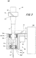
- Fig. 2 is a sectional view of the main part of the stirring mechanism 100 illustrated in Fig. 1 , illustrating a cross section during a stirring operation.
- Fig. 3 is another sectional view of the main part of the stirring mechanism 100 illustrated in Fig. 1 , illustrating a cross section in the case where a portion of the stirring mechanism 100 is removed for maintenance.
- the stirring mechanism 100 illustrated in the above-described drawings is included in the automatic analyzing apparatus, and includes a fixed unit 30 that is fixed to an apparatus body of the automatic analyzing apparatus and a removable unit 50 that is removably attached to the fixed unit 30.
- the fixed unit 30 includes a fixed member 31; a motor 32; a driving helical gear 33; a plurality of bearings, which are illustrated only in Figs. 2 and 3 (a large-diameter bearing 34 and a small-diameter bearing 35 in this example); and a cover member 36 and a sensor member 37, which are illustrated only in Fig. 1 .
- the removable unit 50 includes a support member 51, a driven helical gear 52, a stirring rod 53, and a knob 54. These components will be described in detail below.
- the fixed member 31 is used to fix the stirring mechanism 100 to the apparatus body, and is fixed to the apparatus body with, for example, a driving mechanism 200 (see Figs. 2 and 3 ) for driving the stirring mechanism 100 interposed therebetween.
- the fixed member 31 is a housing member that extends from the driving mechanism 200, and includes a motor-retaining hollow portion 31a in which the motor 32 is retained and a bearing hollow portion 31b (see Fig. 3 ) in which the large-diameter bearing 34 and the small-diameter bearing 35 are retained.
- the motor-retaining hollow portion 31a has a housing that supports the motor 32 such that the motor 32 projects upward with a drive axis ⁇ of the motor 32 extending vertically.
- the bearing hollow portion 31b is a through-hole-shaped space formed in the fixed member 31 so as to extend parallel to the drive axis ⁇ of the motor 32.
- the upper open-end side of the bearing hollow portion 31b serves as an insertion side from which the removable unit 50 is inserted, and the bearings (large-diameter bearing 34 and small-diameter bearing 35 in this example) are coaxially arranged in the bearing hollow portion 31b in decreasing order of inner diameter from the top.
- the bearing hollow portion 31b is formed so that, when the large-diameter bearing 34 and the small-diameter bearing 35 are disposed therein, the region where the small-diameter bearing 35 is disposed has the smallest inner diameter among the regions where the large-diameter bearing 34 and the small-diameter bearing 35 are disposed.
- the bearing hollow portion 31b having such a structure is formed so that, for example, a single axis that is parallel to the drive axis ⁇ of the motor 32 serves as a central axis ⁇ 3 thereof and that the inner diameter thereof decreases with increasing distance from the top toward the bottom.
- the bearing hollow portion 31b retains a bearing other than the large-diameter bearing 34 that is located uppermost and that has the largest diameter (small-diameter bearing 35 in this example) in such a manner that the bearing is embedded in an inner wall 31s of the bearing hollow portion 31b. As illustrated in Fig. 3 , a portion of the inner wall 31s of the bearing hollow portion 31b that is immediately above the small-diameter bearing 35 is flush with an inner wall 35s of the small-diameter bearing 35.
- the inner wall of the bearing hollow portion 31b serves as a guide when the removable unit 50 is inserted from above, so that the removable unit 50 can be inserted without being obstructed by the inner wall of the bearing hollow portion 31b.
- the bearing hollow portion 31b in which the large-diameter bearing 34 and the small-diameter bearing 35 are disposed, may have an inner diameter that decreases stepwise as illustrated, or may include a portion having an inclined inner surface.
- the bearing hollow portion 31b retains the large-diameter bearing 34, which is located uppermost and which has the largest diameter, such that at least an inner race 34b of the large-diameter bearing 34 is upwardly exposed.
- the motor 32 is inserted in the motor-retaining hollow portion 31a of the fixed member 31 and fixed to the fixed member 31 such that the motor 32 projects upward with the drive axis ⁇ thereof extending vertically.
- the motor 32 is preferably rotatable at a high speed, for example, at about 1500 rpm.
- the motor 32 is provided with a controller, which controls the motor 32 during a stirring operation so that a thrust load applied to the driven helical gear 52 described below is a thrust load tP in a direction toward the large-diameter bearing 34 and the small-diameter bearing 35.
- the driving helical gear 33 is a parallel axis gear that meshes with the driven helical gear 52 of the removable unit 50.
- the driving helical gear 33 is provided on the drive axis ⁇ of the motor 32 such that the rotation axis thereof coincides with the drive axis ⁇ of the motor 32.
- the driving helical gear 33 rotates along a horizontal plane when the motor 32 is driven.
- the large-diameter bearing 34 and the small-diameter bearing 35 are disposed in the bearing hollow portion 31b of the fixed member 31 with the central axis ⁇ 3 thereof maintained parallel to the drive axis ⁇ of the motor 32.
- the large-diameter bearing 34 and the small-diameter bearing 35 are arranged in the bearing hollow portion 31b in decreasing order of inner diameter from the top so that a single axis that is parallel to the drive axis ⁇ of the motor 32 serves as the central axis ⁇ 3 thereof.
- the upper side is the insertion side from which the removable unit 50 including the support member 51 is inserted, and the large-diameter bearing 34 disposed at the insertion side has an inner diameter greater than that of the small-diameter bearing 35 disposed at the other side.
- the above-described relationship does not change even when three or more bearings are provided.
- a bearing other than the large-diameter bearing 34 that is located uppermost and that has the largest diameter (small-diameter bearing 35 in this example) is retained such that the bearing is embedded in the inner wall 31s of the bearing hollow portion 31b.
- the inner wall 35s of the small-diameter bearing 35 is flush with a portion of the inner wall 31s of the bearing hollow portion 31b that is immediately above the small-diameter bearing 35.
- the removable unit 50 can be inserted into the bearing hollow portion 31b, in which the large-diameter bearing 34 and the small-diameter bearing 35 are disposed, without being obstructed by the small-diameter bearing 35.
- the large-diameter bearing 34 and the small-diameter bearing 35 described above are rolling bearings, such as ball bearings illustrated in the drawings.
- the large-diameter bearing 34 includes an outer race 34a fixed to the fixed member 31 in the bearing hollow portion 31b, an inner race 34b disposed inside the outer race 34a, and balls 34c disposed between the outer race 34a and the inner race 34b.
- the small-diameter bearing 35 includes an outer race 35a fixed to the fixed member 31 in the bearing hollow portion 31b, an inner race 35b disposed inside the outer race 35a, and balls 35c disposed between the outer race 35a and the inner race 35b.
- the large-diameter bearing 34 which is located uppermost and which has the largest diameter, is fixed to the fixed member 31 such that the upper surface of the inner race 34b is upwardly exposed in the fixed member 31.
- the cover member 36 illustrated in Fig. 1 holds the sensor member 37, which will be described next, and prevents the driven helical gear 52 from being removed.
- the cover member 36 is attached to the fixed member 31.
- the driven helical gear 52 and the knob 54 of the removable unit 50, which will be described next, and the driving helical gear 33 are disposed between the cover member 36 and the fixed member 31.
- the cover member 36 is coupled to the fixed member 31 by, for example, a hinge, and is capable of covering and exposing the accommodating space between the cover member 36 and the fixed member 31.
- cover member there is no particular limitation regarding the above-described cover member as long as the sensor member 37 faces the driving helical gear 33 when the accommodating space between the cover member and the fixed member 31 is covered by the cover member. It is not necessary that the cover member have a function of preventing the driven helical gear 52 from being removed from the driving helical gear 33.
- the sensor member 37 illustrated in Fig. 1 is used to control the rotational speed of the motor 32, and is disposed on a side of the cover member 36 that faces the accommodating space, that is, that faces the fixed member 31.
- the sensor member 37 is, for example, an encoder including a Hall element disposed so as to face the driving helical gear 33 when the cover member 36 is closed.
- the support member 51 is supported by the large-diameter bearing 34 and the small-diameter bearing 35 when the removable unit 50 is inserted in the bearing hollow portion 31b of the fixed member 31 in which the large-diameter bearing 34 and the small-diameter bearing 35 are disposed.
- the support member 51 includes coaxially arranged circular-column-shaped portions having diameters corresponding to the inner diameters of the large-diameter bearing 34 and the small-diameter bearing 35.
- the circular-column-shaped portion having a diameter corresponding to the inner diameter of the large-diameter bearing 34 has the largest diameter.
- the end of the support member 51 at which the circular-column-shaped portion having a small diameter is disposed is defined as the tip end, and the support member 51 is inserted into the bearing hollow portion 31b from the tip end thereof.
- the support member 51 is supported by the large-diameter bearing 34 and the small-diameter bearing 35 at the circular-column-shaped portions having the respective diameters.
- the support member 51 includes a flange portion 51f that is placed on the inner race 34b of the large-diameter bearing 34 when the support member 51 is supported by the large-diameter bearing 34 and the small-diameter bearing 35 disposed in the bearing hollow portion 31b. Accordingly, the inner race 34b of the large-diameter bearing 34 is pressed downward by the flange portion 51f, and the balls 34c are brought into close contact with the outer race 34a and the inner race 34b, so that the support member 51 can be reliably centered.
- the driven helical gear 52 is a parallel axis gear that meshes with the driving helical gear 33 of the fixed unit 30.
- the driven helical gear 52 is coaxially fixed to the support member 51 at an end of the support member 51 at which the flange portion 51f is provided.
- the driven helical gear 52 meshes with the driving helical gear 33 when the support member 51 is inserted in and supported by the large-diameter bearing 34 and the small-diameter bearing 35 disposed in the bearing hollow portion 31b.
- the rotation of the driving helical gear 33 is transmitted to the driven helical gear 52, so that the driven helical gear 52 and the support member 51 rotate together about a single rotation axis ⁇ 5.
- the rotation axis ⁇ 5 coincides with the central axis ⁇ 3 of the bearing hollow portion 31b in which the large-diameter bearing 34 and the small-diameter bearing 35 are disposed, and is maintained parallel to the drive axis ⁇ of the motor 32.
- the stirring rod 53 is inserted into a reaction vessel (not illustrated), and is used to stir a mixed solution of a specimen and a reagent dispensed into the reaction vessel.
- the stirring rod 53 extends coaxially with the support member 51 along the rotation axis ⁇ 5 from an end of the support member 51 opposite to the end adjacent to the driven helical gear 52.
- the shape of the stirring rod 53 is not particularly limited as long as the stirring rod 53 is capable of stirring the mixed solution by rotating about the rotation axis ⁇ 5.
- the stirring rod 53 has the shape of, for example, a flat plate or a screw obtained by twisting a flat plate as illustrated in the figures.
- the knob 54 which is held when the removable unit 50 is attached to or removed from the fixed unit 30, is provided on the rotation axis ⁇ 5 of the driven helical gear 52.
- the knob 54 preferably has the shape of a circular column whose axis coincides with the rotation axis ⁇ 5 of the driven helical gear 52.
- the stirring rod 53 extends along the rotation axis ⁇ 5 of the driven helical gear 52 that meshes with the driving helical gear 33. Therefore, in the illustrated example, when the driving helical gear 33 is rotated counterclockwise when viewed from above, the driven helical gear 52 is rotated by the driving helical gear 33, and receives a thrust load in a direction along the rotation axis ⁇ 5. Accordingly, when the stirring operation is performed, the motor 32 may be driven in a rotation direction such that the driven helical gear 52 receives the thrust load tP in the direction toward the large-diameter bearing 34 and the small-diameter bearing 35.
- the removable unit 50 can be pressed toward the large-diameter bearing 34 and the small-diameter bearing 35 along the rotation axis ⁇ 5. As a result, unsteady movement of the rotation axis ⁇ 5 of the removable unit 50 can be prevented during the stirring operation. Since it is not necessary to consider the risk of gear removal or unsteady movement of the removable unit 50 during the stirring operation, the removable unit 50 can be prevented from being tilted due to a mechanism for reducing such a risk.
- the rotational speed of the stirring rod 53 of the removable unit 50 can be increased, and the stirring efficiency can be increased accordingly.
- the diameter of the screw-shaped stirring rod 53 can be increased. This also leads to an increase in the stirring efficiency.
- the stirring mechanism 100 is structured such that the support member 51 disposed between the driven helical gear 52 and the stirring rod 53 is supported by the large-diameter bearing 34 and the small-diameter bearing 35 having different opening diameters. Accordingly, unsteady movement and tilting of the removable unit 50 can be more reliably prevented.
- the inner race 34b of the large-diameter bearing 34 is pressed toward the large-diameter bearing 34 and the small-diameter bearing 35 by the flange portion 51f of the support member 51, so that the position of the balls 34c between the outer race 34a and the inner race 34b is fixed. Therefore, the support member 51 can be reliably centered.
- the support member 51 is coaxially supported by the large-diameter bearing 34 and the small-diameter bearing 35 having different sizes, the resonance points generated before the rotational speed of the removable unit 50 reaches the maximum rotational speed can be dispersed. This also contributes to the prevention of unsteady movement and tilting of the removable unit 50.
- the stirring mechanism 100 does not need to have a mechanism for preventing gear removal or unsteady movement of the removable unit 50 during the stirring operation. Therefore, the structure can be simplified, so that the removable unit 50 can be easily removed from the fixed unit 30 and replaced for maintenance.
- the motor 32 may be driven in a direction opposite to that in the stirring operation to apply a thrust load to the removable unit 50 in a direction opposite to that of the thrust load tP, so that the removable unit 50 can be more easily removed from the fixed unit 30.
- Fig. 4 is a schematic diagram illustrating an example of the automatic analyzing apparatus according to the embodiment of the present invention.
- the automatic analyzing apparatus 1 illustrated in Fig. 4 is a biochemical analyzer that analyzes a biochemical component contained in a specimen such as blood or urine, and includes stirring mechanisms having the above-described structure.
- the automatic analyzing apparatus 1 includes a sample turntable 2, a dilution turntable 3, a first reagent turntable 4, a second reagent turntable 5, and a reaction turntable 6, which have the shape of a substantially cylindrical container that is open at one end thereof in an axial direction (upper end in Fig. 1 ).
- the automatic analyzing apparatus 1 also includes a dilution stirring device 11, a dilution cleaning device 12, a first reaction stirring device 13, a second reaction stirring device 14, a multi-wavelength photometer 15, and a reaction-vessel cleaning device 16.
- the automatic analyzing apparatus 1 also includes a sample dilution pipette 21, a sampling pipette 22, a first reagent pipette 23, and a second reagent pipette 24.
- the dilution stirring device 11, the first reaction stirring device 13, and the second reaction stirring device 14 each include the above-described stirring mechanism.
- each component of the automatic analyzing apparatus 1 will be described in detail.
- the sample turntable 2 retains a plurality of specimen containers P2 arranged in a plurality of lines concentric to the periphery thereof, and conveys the retained dilution containers P3 in both circumferential directions.
- the specimen containers P2 retained by the sample turntable 2 contain test specimens that are to be tested and control specimens (quality control samples) used for quality control.
- the sample turntable 2 carries various types of test specimens at predetermined locations.
- the sample turntable 2 may retain diluent containers, which contain diluents, in addition to the specimen containers P2.
- the dilution turntable 3 retains a plurality of dilution containers P3 arranged along the periphery thereof, and conveys the retained dilution containers P3 in both circumferential directions. Test specimens that have been sucked out of the specimen containers P2 on the sample turntable 2 and diluted (hereinafter referred to as "diluted specimens") are introduced into the dilution containers P3 retained by the dilution turntable 3.
- the first reagent turntable 4 and the second reagent turntable 5 respectively retain a plural of first reagent containers P4 and P5 arranged along the peripheries thereof, and convey the retained first reagent containers P4 and second reagent containers P5 in both circumferential directions.
- a first reagent is dispensed into the first reagent containers P4 retained by the first reagent turntable 4 from a reagent bottle.
- a second reagent is dispensed into the second reagent containers P5 retained by the second reagent turntable 5 from a reagent bottle.
- the reaction turntable 6 is disposed so as to be surrounded by the dilution turntable 3, the first reagent turntable 4, and the second reagent turntable 5.
- the reaction turntable 6 retains a plurality of reaction vessels P6 along the periphery thereof, and conveys the retained reaction vessels P6 in both circumferential directions.
- a predetermined amount of diluted specimen obtained from one of the dilution containers P3 on the dilution turntable 3 is dispensed into one of the reaction vessels P6 on the reaction turntable 6.
- a predetermined amount of first reagent obtained from one of the first reagent containers P4 on the first reagent turntable 4 or a predetermined amount of second reagent obtained from one of the second reagent containers P5 on the second reagent turntable 5 is dispensed into the reaction vessel P6.
- the diluted specimen is stirred with the first reagent or the second reagent and caused to react with the first reagent or the second reagent in the reaction vessel P6.
- the reaction turntable 6 is provided with a constant temperature bath (not illustrated) that constantly maintains the temperature of the reaction vessels P6 at a certain temperature.
- the dilution stirring device 11 is disposed at the periphery of the dilution turntable 3.
- the dilution stirring device 11 stirs the test specimen and diluent in each dilution container P3.
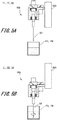
- the dilution stirring device 11 includes the stirring mechanism according to the above-described embodiment and the driving mechanism for driving the stirring mechanism. As illustrated in Figs. 5A and 5B , the dilution stirring device 11 includes the driving mechanism 200 fixed to the apparatus body and the stirring mechanism 100 fixed to the driving mechanism 200.
- the driving mechanism 200 moves the stirring mechanism 100 at a predetermined location on the dilution turntable 3 to insert the stirring rod 53 into the solution (diluted specimen) in one of the dilution containers P3 that is retained by the dilution turntable 3 at the predetermined location. After the stirring rod 53 is inserted into the solution (diluted specimen) in the dilution container P3, the stirring rod 53 is rotated to stir the solution (diluted specimen).
- the dilution cleaning device 12 is disposed at the periphery of the dilution turntable 3.
- the dilution cleaning device 12 cleans the dilution containers P3 after the diluted specimens are sucked out therefrom by a sampling pipette 22, which will be described below.
- the first reaction stirring device 13 and the second reaction stirring device 14 are disposed at the periphery of the reaction turntable 6.
- the first reaction stirring device 13 and the second reaction stirring device 14 stir the diluted specimens together with the first reagent and the second reagent, respectively, in the reaction vessels P6 retained by the reaction turntable 6.
- Each of the first reaction stirring device 13 and the second reaction stirring device 14 includes the stirring mechanism according to the above-described embodiment and the driving mechanism for driving the stirring mechanism. As illustrated in Figs. 5A and 5B , each of the first reaction stirring device 13 and the second reaction stirring device 14 includes the driving mechanism 200 fixed to the apparatus body and the stirring mechanism 100 fixed to the driving mechanism 200.
- the driving mechanism 200 moves the stirring mechanism 100 at a predetermined location on the reaction turntable 6 so that, in one of the reaction vessels P6 retained by the reaction turntable 6 at the predetermined location, the diluted specimen is stirred with the first reagent or the second reagent and caused to react with the first reagent or the second reagent.
- the multi-wavelength photometer 15 which is a measurement unit, is disposed so as to face an outer wall of the reaction turntable 6 at the periphery of the reaction turntable 6.
- the multi-wavelength photometer 15 performs an optical measurement on the diluted specimens that have reacted with the first and second reagent solutions in the reaction vessels P6, and outputs the amounts of various components of the specimens in the form of numerical data representing "absorbance".
- the multi-wavelength photometer 15 detects the reactions of the diluted specimens.
- the reaction-vessel cleaning device 16 cleans the inside of the reaction vessels P6 after the test.
- the reaction-vessel cleaning device 16 includes a plurality of reaction-vessel cleaning nozzles. Similar to a dilution-container cleaning nozzle, the reaction-vessel cleaning nozzles are connected to a waste solution pump (not illustrated) and a detergent pump (not illustrated).
- the sample dilution pipette 21 is disposed at the periphery of the sample turntable 2 and the dilution turntable 3.
- the sample dilution pipette 21 is driven by a dilution-pipette-driving mechanism (not illustrated) so that a tip portion thereof is inserted into one of the specimen containers P2 on the sample turntable 2 and that a predetermined amount of test specimen is sucked into the tip of the pipette, which is filled with a diluent, with a dead air space provided between the diluent and the test specimen.
- the tip portion of the sample dilution pipette 21 is inserted into one of the dilution containers P3 on the dilution turntable 3, and the test specimen that has been sucked and a predetermined amount of diluent (for example, saline) supplied from the sample dilution pipette 21 are discharged into the dilution container P3.
- a predetermined amount of diluent for example, saline
- the sampling pipette 22 is disposed between the dilution turntable 3 and the reaction turntable 6.
- the sampling pipette 22 is driven by a sampling-pipette-driving mechanism (not illustrated) so that a tip portion thereof is inserted into one of the dilution containers P3 on the dilution turntable 3 and that a predetermined amount of diluted specimen is sucked into the tip of the pipette, which is filled with a diluent, with a dead air space provided between the diluent and the diluted specimen. Then, the diluted specimen that has been sucked into the sampling pipette 22 is discharged into one of the reaction vessels P6 on the reaction turntable 6. Thus, the diluted specimen is introduced into the reaction vessel P6.
- the first reagent pipette 23 is disposed between the reaction turntable 6 and the first reagent turntable 4.
- the first reagent pipette 23 is driven by a first-reagent-pipette-driving mechanism (not illustrated) so that a tip portion thereof is inserted into one of the first reagent containers P4 on the first reagent turntable 4 and that a predetermined amount of first reagent is sucked into the tip of the pipette, which is filled with a diluent, with a dead air space provided between the diluent and the first reagent. Then, the first reagent that has been sucked into the first reagent pipette 23 is discharged into one of the reaction vessels P6 on the reaction turntable 6.
- the second reagent pipette 24 is disposed between the reaction turntable 6 and the second reagent turntable 5.
- the second reagent pipette 24 is driven by a second-reagent-pipette-driving mechanism (not illustrated) so that a tip portion thereof is inserted into one of the second reagent containers P5 on the second reagent turntable 5 and that a predetermined amount of second reagent is sucked into the tip of the pipette, which is filled with a diluent, with a dead air space provided between the diluent and the second reagent. Then, the second reagent that has been sucked into the second reagent pipette 24 is discharged into one of the reaction vessels P6 on the reaction turntable 6.
- the dilution stirring device 11, the first reaction stirring device 13, and the second reaction stirring device 14 each include the stirring mechanism according to the above-described embodiment. Therefore, the test specimens can be stirred with the diluent at a high speed and positioning accuracy in the dilution containers P3.
- the diluted specimens can be stirred with the first or second reagent at a high speed and positioning accuracy in the reaction vessels P6. As a result, in particular, the diluted specimens reliably and quickly react with the first or second reagent in the reaction vessels P6, and highly reproducible and accurate analysis can be achieved.
Landscapes
- Chemical & Material Sciences (AREA)
- Chemical Kinetics & Catalysis (AREA)
- General Health & Medical Sciences (AREA)
- Life Sciences & Earth Sciences (AREA)
- Analytical Chemistry (AREA)
- Biochemistry (AREA)
- Physics & Mathematics (AREA)
- General Physics & Mathematics (AREA)
- Immunology (AREA)
- Pathology (AREA)
- Health & Medical Sciences (AREA)
- Automatic Analysis And Handling Materials Therefor (AREA)
- Sampling And Sample Adjustment (AREA)
Abstract
Description
- The present invention relates to automatic analyzing apparatuses, and more particularly to an automatic analyzing apparatus including a stirring mechanism for stirring a sample solution containing a specimen to be analyzed.
- An automatic analyzing apparatus includes a stirring mechanism for stirring a mixed solution in a reaction vessel, the mixed solution containing predetermined amounts of specimen and reagent that have been dispensed into the reaction vessel. A disclosed example of a stirring mechanism includes a plate-shaped stirring element that stirs a mixed solution; a circular-column-shaped support that supports the stirring element; a vibrating unit that vibrates the stirring element; and a rotating unit that rotates the stirring element. In this structure, the rotating unit includes a motor with a rotating shaft that is coupled to the support and a drive circuit that drives the motor. The motor is supported by a stirring arm, and the rotating shaft thereof is disposed on the central axis that passes through the centers of the top and bottom surfaces of the support disposed below the motor (see
PTL 1 given below). - Since the above-described stirring mechanism includes the rotating unit, when the amount of mixed solution is less than or equal to a predetermined amount, the stirring element may be rotated so that the mixed solution in the reaction vessel can be evenly stirred in a short time without spattering the mixed solution upward.
- PTL 1: Japanese Unexamined Patent Application Publication No.
2015-21944 - However, since the above-described stirring mechanism is structured such that the rotating shaft of the motor is disposed on the central axis of the circular-column-shaped support that supports the stirring element, it is difficult to reduce unsteady movement of the plate-shaped stirring element. Therefore, there is a limit to the rotational speed of the stirring element, and the mixed solution cannot be sufficiently stirred in a short time. As a result, it is difficult to achieve highly reproducible and accurate analysis.
- Accordingly, an object of the present invention is to provide an automatic analyzing apparatus that is capable of rotating a stirring rod at a high speed and is thereby capable of achieving highly reproducible and accurate analysis.
- To achieve the above-described object, an automatic analyzing apparatus according to the present invention includes a stirring mechanism including a fixed member fixed to an apparatus body; a motor attached to the fixed member; a driving helical gear provided on a drive axis of the motor; a bearing provided on the fixed member with a central axis thereof maintained parallel to the drive axis of the motor; a support member having a circular column shape and supported so as to be insertable into the bearing from one side of the bearing; a driven helical gear fixed to an end of the support member coaxially with the support member, the driven helical gear meshing with the driving helical gear when the support member is inserted in the bearing; and a stirring rod extending coaxially with the support member from an end of the support member opposite to the end at which the driven helical gear is provided.
- According to the automatic analyzing apparatus of the present invention, the stirring rod can be rotated at a high speed, and highly reproducible and accurate analysis can therefore be achieved.
-
- [
Fig. 1] Fig. 1 is a perspective view of a stirring mechanism of an automatic analyzing apparatus according to an embodiment. - [
Fig. 2] Fig. 2 is a sectional view of the main part of the stirring mechanism illustrated inFig. 1 . - [
Fig. 3] Fig. 3 is another sectional view of the main part of the stirring mechanism illustrated inFig. 1 . - [
Fig. 4] Fig. 4 is a schematic diagram illustrating the automatic analyzing apparatus according to the embodiment. - [
Fig. 5] Fig. 5 illustrates the operation of the stirring mechanism of the automatic analyzing apparatus according to the embodiment. - In the following description, an embodiment of a stirring mechanism included in an automatic analyzing apparatus of the present invention and the structure of the automatic analyzing apparatus of the present invention including the stirring mechanism will be described in that order with reference to the drawings.
-
Fig. 1 is a perspective view of astirring mechanism 100 of an automatic analyzing apparatus according to an embodiment.Fig. 2 is a sectional view of the main part of thestirring mechanism 100 illustrated inFig. 1 , illustrating a cross section during a stirring operation.Fig. 3 is another sectional view of the main part of thestirring mechanism 100 illustrated inFig. 1 , illustrating a cross section in the case where a portion of thestirring mechanism 100 is removed for maintenance. - The
stirring mechanism 100 illustrated in the above-described drawings is included in the automatic analyzing apparatus, and includes a fixedunit 30 that is fixed to an apparatus body of the automatic analyzing apparatus and aremovable unit 50 that is removably attached to thefixed unit 30. Thefixed unit 30 includes a fixedmember 31; amotor 32; a drivinghelical gear 33; a plurality of bearings, which are illustrated only inFigs. 2 and3 (a large-diameter bearing 34 and a small-diameter bearing 35 in this example); and acover member 36 and asensor member 37, which are illustrated only inFig. 1 . Theremovable unit 50 includes asupport member 51, a drivenhelical gear 52, astirring rod 53, and aknob 54. These components will be described in detail below. - The fixed
member 31 is used to fix thestirring mechanism 100 to the apparatus body, and is fixed to the apparatus body with, for example, a driving mechanism 200 (seeFigs. 2 and3 ) for driving thestirring mechanism 100 interposed therebetween. The fixedmember 31 is a housing member that extends from thedriving mechanism 200, and includes a motor-retaininghollow portion 31a in which themotor 32 is retained and a bearinghollow portion 31b (seeFig. 3 ) in which the large-diameter bearing 34 and the small-diameter bearing 35 are retained. - The motor-retaining
hollow portion 31a has a housing that supports themotor 32 such that themotor 32 projects upward with a drive axis φ of themotor 32 extending vertically. - The bearing
hollow portion 31b is a through-hole-shaped space formed in the fixedmember 31 so as to extend parallel to the drive axis φ of themotor 32. The upper open-end side of the bearinghollow portion 31b serves as an insertion side from which theremovable unit 50 is inserted, and the bearings (large-diameter bearing 34 and small-diameter bearing 35 in this example) are coaxially arranged in the bearinghollow portion 31b in decreasing order of inner diameter from the top. - The bearing
hollow portion 31b is formed so that, when the large-diameter bearing 34 and the small-diameter bearing 35 are disposed therein, the region where the small-diameter bearing 35 is disposed has the smallest inner diameter among the regions where the large-diameter bearing 34 and the small-diameter bearing 35 are disposed. The bearinghollow portion 31b having such a structure is formed so that, for example, a single axis that is parallel to the drive axis φ of themotor 32 serves as a central axis φ3 thereof and that the inner diameter thereof decreases with increasing distance from the top toward the bottom. - The bearing
hollow portion 31b retains a bearing other than the large-diameter bearing 34 that is located uppermost and that has the largest diameter (small-diameter bearing 35 in this example) in such a manner that the bearing is embedded in aninner wall 31s of the bearinghollow portion 31b. As illustrated inFig. 3 , a portion of theinner wall 31s of the bearinghollow portion 31b that is immediately above the small-diameter bearing 35 is flush with aninner wall 35s of the small-diameter bearing 35. - Accordingly, the inner wall of the bearing
hollow portion 31b serves as a guide when theremovable unit 50 is inserted from above, so that theremovable unit 50 can be inserted without being obstructed by the inner wall of the bearinghollow portion 31b. The bearinghollow portion 31b, in which the large-diameter bearing 34 and the small-diameter bearing 35 are disposed, may have an inner diameter that decreases stepwise as illustrated, or may include a portion having an inclined inner surface. - When the large-diameter bearing 34 and the small-diameter bearing 35, which will be described below, are rolling bearings, such as ball bearings, the bearing
hollow portion 31b retains the large-diameter bearing 34, which is located uppermost and which has the largest diameter, such that at least aninner race 34b of the large-diameter bearing 34 is upwardly exposed. - The
motor 32 is inserted in the motor-retaininghollow portion 31a of the fixedmember 31 and fixed to thefixed member 31 such that themotor 32 projects upward with the drive axis φ thereof extending vertically. Themotor 32 is preferably rotatable at a high speed, for example, at about 1500 rpm. - Although not illustrated, the
motor 32 is provided with a controller, which controls themotor 32 during a stirring operation so that a thrust load applied to the drivenhelical gear 52 described below is a thrust load tP in a direction toward the large-diameter bearing 34 and the small-diameter bearing 35. - The driving
helical gear 33 is a parallel axis gear that meshes with the drivenhelical gear 52 of theremovable unit 50. The drivinghelical gear 33 is provided on the drive axis φ of themotor 32 such that the rotation axis thereof coincides with the drive axis φ of themotor 32. The drivinghelical gear 33 rotates along a horizontal plane when themotor 32 is driven. - The large-diameter bearing 34 and the small-diameter bearing 35 are disposed in the bearing
hollow portion 31b of the fixedmember 31 with the central axis φ3 thereof maintained parallel to the drive axis φ of themotor 32. As described above in the description of the structure of the bearinghollow portion 31b, the large-diameter bearing 34 and the small-diameter bearing 35 are arranged in the bearinghollow portion 31b in decreasing order of inner diameter from the top so that a single axis that is parallel to the drive axis φ of themotor 32 serves as the central axis φ3 thereof. In the illustrated example, the upper side is the insertion side from which theremovable unit 50 including thesupport member 51 is inserted, and the large-diameter bearing 34 disposed at the insertion side has an inner diameter greater than that of the small-diameter bearing 35 disposed at the other side. The above-described relationship does not change even when three or more bearings are provided. - Among the large-diameter bearing 34 and the small-diameter bearing 35, a bearing other than the large-diameter bearing 34 that is located uppermost and that has the largest diameter (small-diameter bearing 35 in this example) is retained such that the bearing is embedded in the
inner wall 31s of the bearinghollow portion 31b. As illustrated inFig. 3 , theinner wall 35s of the small-diameter bearing 35 is flush with a portion of theinner wall 31s of the bearinghollow portion 31b that is immediately above the small-diameter bearing 35. - Accordingly, the
removable unit 50 can be inserted into the bearinghollow portion 31b, in which the large-diameter bearing 34 and the small-diameter bearing 35 are disposed, without being obstructed by the small-diameter bearing 35. - Preferably, the large-diameter bearing 34 and the small-diameter bearing 35 described above are rolling bearings, such as ball bearings illustrated in the drawings. In this case, the large-
diameter bearing 34 includes anouter race 34a fixed to the fixedmember 31 in the bearinghollow portion 31b, aninner race 34b disposed inside theouter race 34a, andballs 34c disposed between theouter race 34a and theinner race 34b. Similarly, the small-diameter bearing 35 includes anouter race 35a fixed to the fixedmember 31 in the bearinghollow portion 31b, aninner race 35b disposed inside theouter race 35a, and balls 35c disposed between theouter race 35a and theinner race 35b. - In this case, the large-
diameter bearing 34, which is located uppermost and which has the largest diameter, is fixed to the fixedmember 31 such that the upper surface of theinner race 34b is upwardly exposed in the fixedmember 31. - The
cover member 36 illustrated inFig. 1 holds thesensor member 37, which will be described next, and prevents the drivenhelical gear 52 from being removed. Thecover member 36 is attached to the fixedmember 31. The drivenhelical gear 52 and theknob 54 of theremovable unit 50, which will be described next, and the drivinghelical gear 33 are disposed between thecover member 36 and the fixedmember 31. Thecover member 36 is coupled to the fixedmember 31 by, for example, a hinge, and is capable of covering and exposing the accommodating space between thecover member 36 and the fixedmember 31. - There is no particular limitation regarding the above-described cover member as long as the
sensor member 37 faces the drivinghelical gear 33 when the accommodating space between the cover member and the fixedmember 31 is covered by the cover member. It is not necessary that the cover member have a function of preventing the drivenhelical gear 52 from being removed from the drivinghelical gear 33. - The
sensor member 37 illustrated inFig. 1 is used to control the rotational speed of themotor 32, and is disposed on a side of thecover member 36 that faces the accommodating space, that is, that faces the fixedmember 31. Thesensor member 37 is, for example, an encoder including a Hall element disposed so as to face the drivinghelical gear 33 when thecover member 36 is closed. - As illustrated in
Figs. 2 and3 , thesupport member 51 is supported by the large-diameter bearing 34 and the small-diameter bearing 35 when theremovable unit 50 is inserted in the bearinghollow portion 31b of the fixedmember 31 in which the large-diameter bearing 34 and the small-diameter bearing 35 are disposed. Thesupport member 51 includes coaxially arranged circular-column-shaped portions having diameters corresponding to the inner diameters of the large-diameter bearing 34 and the small-diameter bearing 35. Among the circular-column-shaped portions, the circular-column-shaped portion having a diameter corresponding to the inner diameter of the large-diameter bearing 34 has the largest diameter. Accordingly, the end of thesupport member 51 at which the circular-column-shaped portion having a small diameter is disposed is defined as the tip end, and thesupport member 51 is inserted into the bearinghollow portion 31b from the tip end thereof. Thesupport member 51 is supported by the large-diameter bearing 34 and the small-diameter bearing 35 at the circular-column-shaped portions having the respective diameters. - The
support member 51 includes aflange portion 51f that is placed on theinner race 34b of the large-diameter bearing 34 when thesupport member 51 is supported by the large-diameter bearing 34 and the small-diameter bearing 35 disposed in the bearinghollow portion 31b. Accordingly, theinner race 34b of the large-diameter bearing 34 is pressed downward by theflange portion 51f, and theballs 34c are brought into close contact with theouter race 34a and theinner race 34b, so that thesupport member 51 can be reliably centered. - The driven
helical gear 52 is a parallel axis gear that meshes with the drivinghelical gear 33 of the fixedunit 30. The drivenhelical gear 52 is coaxially fixed to thesupport member 51 at an end of thesupport member 51 at which theflange portion 51f is provided. The drivenhelical gear 52 meshes with the drivinghelical gear 33 when thesupport member 51 is inserted in and supported by the large-diameter bearing 34 and the small-diameter bearing 35 disposed in the bearinghollow portion 31b. - When the
motor 32 is driven to rotate the drivinghelical gear 33 along a horizontal plane, the rotation of the drivinghelical gear 33 is transmitted to the drivenhelical gear 52, so that the drivenhelical gear 52 and thesupport member 51 rotate together about a single rotation axis φ5. At this time, the rotation axis φ5 coincides with the central axis φ3 of the bearinghollow portion 31b in which the large-diameter bearing 34 and the small-diameter bearing 35 are disposed, and is maintained parallel to the drive axis φ of themotor 32. - The stirring
rod 53 is inserted into a reaction vessel (not illustrated), and is used to stir a mixed solution of a specimen and a reagent dispensed into the reaction vessel. The stirringrod 53 extends coaxially with thesupport member 51 along the rotation axis φ5 from an end of thesupport member 51 opposite to the end adjacent to the drivenhelical gear 52. The shape of the stirringrod 53 is not particularly limited as long as the stirringrod 53 is capable of stirring the mixed solution by rotating about the rotation axis φ5. The stirringrod 53 has the shape of, for example, a flat plate or a screw obtained by twisting a flat plate as illustrated in the figures. - The
knob 54, which is held when theremovable unit 50 is attached to or removed from the fixedunit 30, is provided on the rotation axis φ5 of the drivenhelical gear 52. Theknob 54 preferably has the shape of a circular column whose axis coincides with the rotation axis φ5 of the drivenhelical gear 52. Thus, the influence of theknob 54 on the rotation of theremovable unit 50 about the rotation axis φ5 can be eliminated. - In the
stirring mechanism 100 having the above-described structure, the stirringrod 53 extends along the rotation axis φ5 of the drivenhelical gear 52 that meshes with the drivinghelical gear 33. Therefore, in the illustrated example, when the drivinghelical gear 33 is rotated counterclockwise when viewed from above, the drivenhelical gear 52 is rotated by the drivinghelical gear 33, and receives a thrust load in a direction along the rotation axis φ5. Accordingly, when the stirring operation is performed, themotor 32 may be driven in a rotation direction such that the drivenhelical gear 52 receives the thrust load tP in the direction toward the large-diameter bearing 34 and the small-diameter bearing 35. Thus, theremovable unit 50 can be pressed toward the large-diameter bearing 34 and the small-diameter bearing 35 along the rotation axis φ5. As a result, unsteady movement of the rotation axis φ5 of theremovable unit 50 can be prevented during the stirring operation. Since it is not necessary to consider the risk of gear removal or unsteady movement of theremovable unit 50 during the stirring operation, theremovable unit 50 can be prevented from being tilted due to a mechanism for reducing such a risk. - Therefore, the rotational speed of the stirring
rod 53 of theremovable unit 50 can be increased, and the stirring efficiency can be increased accordingly. In addition, since unsteady movement and tilting of theremovable unit 50 can be prevented, the diameter of the screw-shapedstirring rod 53 can be increased. This also leads to an increase in the stirring efficiency. - The
stirring mechanism 100 is structured such that thesupport member 51 disposed between the drivenhelical gear 52 and the stirringrod 53 is supported by the large-diameter bearing 34 and the small-diameter bearing 35 having different opening diameters. Accordingly, unsteady movement and tilting of theremovable unit 50 can be more reliably prevented. In addition, during the above-described stirring operation, theinner race 34b of the large-diameter bearing 34 is pressed toward the large-diameter bearing 34 and the small-diameter bearing 35 by theflange portion 51f of thesupport member 51, so that the position of theballs 34c between theouter race 34a and theinner race 34b is fixed. Therefore, thesupport member 51 can be reliably centered. In addition, since thesupport member 51 is coaxially supported by the large-diameter bearing 34 and the small-diameter bearing 35 having different sizes, the resonance points generated before the rotational speed of theremovable unit 50 reaches the maximum rotational speed can be dispersed. This also contributes to the prevention of unsteady movement and tilting of theremovable unit 50. - Furthermore, as described above, the
stirring mechanism 100 does not need to have a mechanism for preventing gear removal or unsteady movement of theremovable unit 50 during the stirring operation. Therefore, the structure can be simplified, so that theremovable unit 50 can be easily removed from the fixedunit 30 and replaced for maintenance. In addition, themotor 32 may be driven in a direction opposite to that in the stirring operation to apply a thrust load to theremovable unit 50 in a direction opposite to that of the thrust load tP, so that theremovable unit 50 can be more easily removed from the fixedunit 30. -
Fig. 4 is a schematic diagram illustrating an example of the automatic analyzing apparatus according to the embodiment of the present invention. Theautomatic analyzing apparatus 1 illustrated inFig. 4 is a biochemical analyzer that analyzes a biochemical component contained in a specimen such as blood or urine, and includes stirring mechanisms having the above-described structure. - The
automatic analyzing apparatus 1 includes asample turntable 2, a dilution turntable 3, afirst reagent turntable 4, asecond reagent turntable 5, and areaction turntable 6, which have the shape of a substantially cylindrical container that is open at one end thereof in an axial direction (upper end inFig. 1 ). Theautomatic analyzing apparatus 1 also includes adilution stirring device 11, adilution cleaning device 12, a firstreaction stirring device 13, a secondreaction stirring device 14, amulti-wavelength photometer 15, and a reaction-vessel cleaning device 16. Theautomatic analyzing apparatus 1 also includes asample dilution pipette 21, asampling pipette 22, afirst reagent pipette 23, and asecond reagent pipette 24. - In the
automatic analyzing apparatus 1 according to the present embodiment, among the above-described components, thedilution stirring device 11, the firstreaction stirring device 13, and the secondreaction stirring device 14 each include the above-described stirring mechanism. In the following description, each component of theautomatic analyzing apparatus 1 will be described in detail. - The
sample turntable 2 retains a plurality of specimen containers P2 arranged in a plurality of lines concentric to the periphery thereof, and conveys the retained dilution containers P3 in both circumferential directions. The specimen containers P2 retained by thesample turntable 2 contain test specimens that are to be tested and control specimens (quality control samples) used for quality control. Thesample turntable 2 carries various types of test specimens at predetermined locations. Thesample turntable 2 may retain diluent containers, which contain diluents, in addition to the specimen containers P2. - The dilution turntable 3 retains a plurality of dilution containers P3 arranged along the periphery thereof, and conveys the retained dilution containers P3 in both circumferential directions. Test specimens that have been sucked out of the specimen containers P2 on the
sample turntable 2 and diluted (hereinafter referred to as "diluted specimens") are introduced into the dilution containers P3 retained by the dilution turntable 3. - The
first reagent turntable 4 and thesecond reagent turntable 5 respectively retain a plural of first reagent containers P4 and P5 arranged along the peripheries thereof, and convey the retained first reagent containers P4 and second reagent containers P5 in both circumferential directions. A first reagent is dispensed into the first reagent containers P4 retained by thefirst reagent turntable 4 from a reagent bottle. A second reagent is dispensed into the second reagent containers P5 retained by thesecond reagent turntable 5 from a reagent bottle. - The
reaction turntable 6 is disposed so as to be surrounded by the dilution turntable 3, thefirst reagent turntable 4, and thesecond reagent turntable 5. Thereaction turntable 6 retains a plurality of reaction vessels P6 along the periphery thereof, and conveys the retained reaction vessels P6 in both circumferential directions. A predetermined amount of diluted specimen obtained from one of the dilution containers P3 on the dilution turntable 3 is dispensed into one of the reaction vessels P6 on thereaction turntable 6. In addition, a predetermined amount of first reagent obtained from one of the first reagent containers P4 on thefirst reagent turntable 4 or a predetermined amount of second reagent obtained from one of the second reagent containers P5 on thesecond reagent turntable 5 is dispensed into the reaction vessel P6. The diluted specimen is stirred with the first reagent or the second reagent and caused to react with the first reagent or the second reagent in the reaction vessel P6. - The
reaction turntable 6 is provided with a constant temperature bath (not illustrated) that constantly maintains the temperature of the reaction vessels P6 at a certain temperature. - The
dilution stirring device 11 is disposed at the periphery of the dilution turntable 3. Thedilution stirring device 11 stirs the test specimen and diluent in each dilution container P3. Thedilution stirring device 11 includes the stirring mechanism according to the above-described embodiment and the driving mechanism for driving the stirring mechanism. As illustrated inFigs. 5A and 5B , thedilution stirring device 11 includes thedriving mechanism 200 fixed to the apparatus body and thestirring mechanism 100 fixed to thedriving mechanism 200. Thedriving mechanism 200 moves thestirring mechanism 100 at a predetermined location on the dilution turntable 3 to insert the stirringrod 53 into the solution (diluted specimen) in one of the dilution containers P3 that is retained by the dilution turntable 3 at the predetermined location. After the stirringrod 53 is inserted into the solution (diluted specimen) in the dilution container P3, the stirringrod 53 is rotated to stir the solution (diluted specimen). - The
dilution cleaning device 12 is disposed at the periphery of the dilution turntable 3. Thedilution cleaning device 12 cleans the dilution containers P3 after the diluted specimens are sucked out therefrom by asampling pipette 22, which will be described below. - The first
reaction stirring device 13 and the secondreaction stirring device 14 are disposed at the periphery of thereaction turntable 6. The firstreaction stirring device 13 and the secondreaction stirring device 14 stir the diluted specimens together with the first reagent and the second reagent, respectively, in the reaction vessels P6 retained by thereaction turntable 6. Each of the firstreaction stirring device 13 and the secondreaction stirring device 14 includes the stirring mechanism according to the above-described embodiment and the driving mechanism for driving the stirring mechanism. As illustrated inFigs. 5A and 5B , each of the firstreaction stirring device 13 and the secondreaction stirring device 14 includes thedriving mechanism 200 fixed to the apparatus body and thestirring mechanism 100 fixed to thedriving mechanism 200. Thedriving mechanism 200 moves thestirring mechanism 100 at a predetermined location on thereaction turntable 6 so that, in one of the reaction vessels P6 retained by thereaction turntable 6 at the predetermined location, the diluted specimen is stirred with the first reagent or the second reagent and caused to react with the first reagent or the second reagent. - The
multi-wavelength photometer 15, which is a measurement unit, is disposed so as to face an outer wall of thereaction turntable 6 at the periphery of thereaction turntable 6. Themulti-wavelength photometer 15 performs an optical measurement on the diluted specimens that have reacted with the first and second reagent solutions in the reaction vessels P6, and outputs the amounts of various components of the specimens in the form of numerical data representing "absorbance". Thus, themulti-wavelength photometer 15 detects the reactions of the diluted specimens. - The reaction-
vessel cleaning device 16 cleans the inside of the reaction vessels P6 after the test. The reaction-vessel cleaning device 16 includes a plurality of reaction-vessel cleaning nozzles. Similar to a dilution-container cleaning nozzle, the reaction-vessel cleaning nozzles are connected to a waste solution pump (not illustrated) and a detergent pump (not illustrated). - The
sample dilution pipette 21 is disposed at the periphery of thesample turntable 2 and the dilution turntable 3. Thesample dilution pipette 21 is driven by a dilution-pipette-driving mechanism (not illustrated) so that a tip portion thereof is inserted into one of the specimen containers P2 on thesample turntable 2 and that a predetermined amount of test specimen is sucked into the tip of the pipette, which is filled with a diluent, with a dead air space provided between the diluent and the test specimen. Then, the tip portion of thesample dilution pipette 21 is inserted into one of the dilution containers P3 on the dilution turntable 3, and the test specimen that has been sucked and a predetermined amount of diluent (for example, saline) supplied from thesample dilution pipette 21 are discharged into the dilution container P3. As a result, the test specimen is diluted by a predetermined factor in the dilution container P3. After that, thesample dilution pipette 21 is cleaned by a cleaning device. - The
sampling pipette 22 is disposed between the dilution turntable 3 and thereaction turntable 6. Thesampling pipette 22 is driven by a sampling-pipette-driving mechanism (not illustrated) so that a tip portion thereof is inserted into one of the dilution containers P3 on the dilution turntable 3 and that a predetermined amount of diluted specimen is sucked into the tip of the pipette, which is filled with a diluent, with a dead air space provided between the diluent and the diluted specimen. Then, the diluted specimen that has been sucked into thesampling pipette 22 is discharged into one of the reaction vessels P6 on thereaction turntable 6. Thus, the diluted specimen is introduced into the reaction vessel P6. - The
first reagent pipette 23 is disposed between thereaction turntable 6 and thefirst reagent turntable 4. Thefirst reagent pipette 23 is driven by a first-reagent-pipette-driving mechanism (not illustrated) so that a tip portion thereof is inserted into one of the first reagent containers P4 on thefirst reagent turntable 4 and that a predetermined amount of first reagent is sucked into the tip of the pipette, which is filled with a diluent, with a dead air space provided between the diluent and the first reagent. Then, the first reagent that has been sucked into thefirst reagent pipette 23 is discharged into one of the reaction vessels P6 on thereaction turntable 6. - The
second reagent pipette 24 is disposed between thereaction turntable 6 and thesecond reagent turntable 5. Thesecond reagent pipette 24 is driven by a second-reagent-pipette-driving mechanism (not illustrated) so that a tip portion thereof is inserted into one of the second reagent containers P5 on thesecond reagent turntable 5 and that a predetermined amount of second reagent is sucked into the tip of the pipette, which is filled with a diluent, with a dead air space provided between the diluent and the second reagent. Then, the second reagent that has been sucked into thesecond reagent pipette 24 is discharged into one of the reaction vessels P6 on thereaction turntable 6. - In the
automatic analyzing apparatus 1 having the above-described structure, thedilution stirring device 11, the firstreaction stirring device 13, and the secondreaction stirring device 14 each include the stirring mechanism according to the above-described embodiment. Therefore, the test specimens can be stirred with the diluent at a high speed and positioning accuracy in the dilution containers P3. In addition, the diluted specimens can be stirred with the first or second reagent at a high speed and positioning accuracy in the reaction vessels P6. As a result, in particular, the diluted specimens reliably and quickly react with the first or second reagent in the reaction vessels P6, and highly reproducible and accurate analysis can be achieved. -
- 1 automatic analyzing apparatus
- 31 fixed member
- 31b bearing hollow portion
- 31s inner wall (bearing hollow portion)
- 32 motor
- φ drive axis
- 33 driving helical gear
- 35 bearing
- 35b inner race (bearing)
- 35s inner wall (bearing)
- φ3 central axis (bearing)
- 51 support member
- 51f flange (support member)
- φ5 rotation axis (removable unit including support member)
- 52 driven helical gear
- 53 stirring rod
- 54 knob
- 100 stirring mechanism
Claims (5)
- An automatic analyzing apparatus comprising:
a stirring mechanism includinga fixed member fixed to an apparatus body,a motor attached to the fixed member,a driving helical gear provided on a drive axis of the motor,a bearing provided on the fixed member with a central axis thereof maintained parallel to the drive axis of the motor,a support member having a circular column shape and supported so as to be insertable into the bearing from one side of the bearing,a driven helical gear fixed to an end of the support member coaxially with the support member, the driven helical gear meshing with the driving helical gear when the support member is inserted in the bearing, anda stirring rod extending coaxially with the support member from an end of the support member opposite to the end to which the driven helical gear is fixed. - The automatic analyzing apparatus according to Claim 1, wherein a plurality of the bearings are arranged coaxially, one of the bearings that is disposed near a side from which the support member is inserted having an inner diameter greater than an inner diameter of another one of the bearings that is disposed near the other side, and
wherein the support member includes a plurality of circular-column-shaped portions having diameters corresponding to the inner diameters of the bearings, and is supported by the bearings at the circular-column-shaped portions. - The automatic analyzing apparatus according to Claim 2, wherein the fixed member has a hollow portion in which the bearings are disposed, and
wherein one or more of the bearings other than the bearing having a largest diameter are embedded in an inner wall of the hollow portion so that inner walls thereof are flush with the inner wall of the hollow portion. - The automatic analyzing apparatus according to any one of Claims 1 to 3, wherein the bearing is a rolling bearing, and
wherein the support member includes a flange placed on an inner race of the bearing when the support member is inserted in the bearing. - The automatic analyzing apparatus according to any one of Claims 1 to 4, wherein a knob is provided on a rotation axis of the driven helical gear so as to project from the driven helical gear.
Applications Claiming Priority (2)
| Application Number | Priority Date | Filing Date | Title |
|---|---|---|---|
| JP2015244843A JP6573542B2 (en) | 2015-12-16 | 2015-12-16 | Automatic analyzer |
| PCT/JP2016/086495 WO2017104523A1 (en) | 2015-12-16 | 2016-12-08 | Automatic analyzing apparatus |
Publications (3)
| Publication Number | Publication Date |
|---|---|
| EP3392659A1 true EP3392659A1 (en) | 2018-10-24 |
| EP3392659A4 EP3392659A4 (en) | 2019-07-17 |
| EP3392659B1 EP3392659B1 (en) | 2020-08-19 |
Family
ID=59056416
Family Applications (1)
| Application Number | Title | Priority Date | Filing Date |
|---|---|---|---|
| EP16875503.1A Active EP3392659B1 (en) | 2015-12-16 | 2016-12-08 | Automatic analyzing apparatus |
Country Status (5)
| Country | Link |
|---|---|
| US (1) | US10926232B2 (en) |
| EP (1) | EP3392659B1 (en) |
| JP (1) | JP6573542B2 (en) |
| CN (1) | CN108369237B (en) |
| WO (1) | WO2017104523A1 (en) |
Families Citing this family (6)
| Publication number | Priority date | Publication date | Assignee | Title |
|---|---|---|---|---|
| CN111744402B (en) * | 2020-07-09 | 2022-10-11 | 安徽森普新型材料发展有限公司 | High-efficient stirred tank device |
| EP4200069A4 (en) | 2020-08-19 | 2024-07-31 | SM Intellectual Technologies LLC | TRINONUCLEAR BASIC IRON(III) ACETATE, SOLID ABSORBENT AGENTS AND METHODS FOR REMOVING OR SWEETENING MERCAPTANS FROM HYDROCARBON STREAMS |
| JP7102600B1 (en) | 2021-12-10 | 2022-07-19 | 株式会社西村ケミテック | Liquid injection and extraction equipment |
| JP7214029B1 (en) | 2021-12-10 | 2023-01-27 | 株式会社西村ケミテック | liquid injection and extraction equipment |
| CN115025687B (en) * | 2022-05-09 | 2023-07-21 | 四川环科美能环保科技有限公司 | Environment-friendly paint processing device |
| WO2025189475A1 (en) * | 2024-03-15 | 2025-09-18 | 深圳华大生命科学研究院 | Sample mixing device and sample mixing method |
Family Cites Families (11)
| Publication number | Priority date | Publication date | Assignee | Title |
|---|---|---|---|---|
| US3796108A (en) | 1972-12-18 | 1974-03-12 | Chemineer | Right angle speed reducer |
| JPS604354B2 (en) | 1976-06-29 | 1985-02-02 | 睦和 郷 | Electric shutter water pressure release device in case of fire |
| JP3162171B2 (en) * | 1992-04-28 | 2001-04-25 | オリンパス光学工業株式会社 | Stirrer for automatic chemical analyzer |
| JPH08131802A (en) * | 1994-11-10 | 1996-05-28 | Nippon Gear Co Ltd | Motor-controlled agitator |
| US5960671A (en) * | 1997-09-30 | 1999-10-05 | Philadelphia Gear Corp. | Eccentric pivotable mounting for changing gear reduction ratios |
| WO2000021651A1 (en) * | 1998-10-13 | 2000-04-20 | Takeuchi Manufacturing Co., Ltd. | An agitator |
| US6058793A (en) * | 1999-01-19 | 2000-05-09 | Chemineer, Inc. | Parallel shaft speed reducer with sump and dry well |
| US6715913B2 (en) * | 2002-03-29 | 2004-04-06 | Spx Corporation | Shaft bearing support method and apparatus |
| JP2005291730A (en) * | 2004-03-31 | 2005-10-20 | Fujifilm Techno Products Co Ltd | Biochemical analyzer |
| JP6176842B2 (en) | 2013-07-23 | 2017-08-09 | 東芝メディカルシステムズ株式会社 | Automatic analyzer |
| CN204619836U (en) * | 2015-05-14 | 2015-09-09 | 牛洪芝 | A vertical shuttle type stirring device |
-
2015
- 2015-12-16 JP JP2015244843A patent/JP6573542B2/en active Active
-
2016
- 2016-12-08 CN CN201680071846.1A patent/CN108369237B/en active Active
- 2016-12-08 EP EP16875503.1A patent/EP3392659B1/en active Active
- 2016-12-08 WO PCT/JP2016/086495 patent/WO2017104523A1/en not_active Ceased
- 2016-12-08 US US16/062,298 patent/US10926232B2/en active Active
Also Published As
| Publication number | Publication date |
|---|---|
| EP3392659A4 (en) | 2019-07-17 |
| WO2017104523A1 (en) | 2017-06-22 |
| JP2017110989A (en) | 2017-06-22 |
| US20180369769A1 (en) | 2018-12-27 |
| CN108369237A (en) | 2018-08-03 |
| CN108369237B (en) | 2021-12-21 |
| JP6573542B2 (en) | 2019-09-11 |
| US10926232B2 (en) | 2021-02-23 |
| EP3392659B1 (en) | 2020-08-19 |
Similar Documents
| Publication | Publication Date | Title |
|---|---|---|
| EP3392659B1 (en) | Automatic analyzing apparatus | |
| JP4251627B2 (en) | Chemical analyzer and dispensing method thereof | |
| JP5542379B2 (en) | Stirring device, stirring method, and automatic gene testing device | |
| JP5400021B2 (en) | Automatic analyzer | |
| EP4071484B1 (en) | Automated analyzer | |
| WO2010087137A1 (en) | Autoanalyzer | |
| JP5192455B2 (en) | Automatic analyzer | |
| JP2009025167A (en) | Automatic analyzer | |
| EP3546953A1 (en) | Apparatus and method for automated analysis | |
| EP3971583B1 (en) | Automatic analyzing device | |
| JPH05126835A (en) | Dispensing apparatus | |
| EP4471428A1 (en) | Automatic analysis device and automatic analysis method | |
| JP7499881B2 (en) | Automated Analysis Equipment | |
| JP6808574B2 (en) | Container storage unit and automatic analyzer | |
| JP7773353B2 (en) | automatic analyzer | |
| CN113711054B (en) | Automatic analysis device | |
| CN107037226A (en) | Analytical equipment | |
| JP4713401B2 (en) | Stirring device and automatic analyzer using the same | |
| JP4248471B2 (en) | Automatic analyzer | |
| JP7685061B2 (en) | automatic analyzer | |
| EP4571322A1 (en) | Dispensing probe device and automatic analysis device | |
| JP2005291730A (en) | Biochemical analyzer | |
| JPH0798320A (en) | Biochemical automatic analyzer | |
| JP7105112B2 (en) | Dispensing unit, automatic analyzer, and liquid level detection judgment method | |
| JP7217140B2 (en) | Automatic analyzer and automatic analysis method |
Legal Events
| Date | Code | Title | Description |
|---|---|---|---|
| STAA | Information on the status of an ep patent application or granted ep patent |
Free format text: STATUS: THE INTERNATIONAL PUBLICATION HAS BEEN MADE |
|
| PUAI | Public reference made under article 153(3) epc to a published international application that has entered the european phase |
Free format text: ORIGINAL CODE: 0009012 |
|
| STAA | Information on the status of an ep patent application or granted ep patent |
Free format text: STATUS: REQUEST FOR EXAMINATION WAS MADE |
|
| 17P | Request for examination filed |
Effective date: 20180613 |
|
| AK | Designated contracting states |
Kind code of ref document: A1 Designated state(s): AL AT BE BG CH CY CZ DE DK EE ES FI FR GB GR HR HU IE IS IT LI LT LU LV MC MK MT NL NO PL PT RO RS SE SI SK SM TR |
|
| AX | Request for extension of the european patent |
Extension state: BA ME |
|
| DAV | Request for validation of the european patent (deleted) | ||
| DAX | Request for extension of the european patent (deleted) | ||
| A4 | Supplementary search report drawn up and despatched |
Effective date: 20190617 |
|
| RIC1 | Information provided on ipc code assigned before grant |
Ipc: G01N 1/38 20060101ALI20190611BHEP Ipc: B01F 11/00 20060101ALI20190611BHEP Ipc: B01F 1/00 20060101ALI20190611BHEP Ipc: G01N 35/02 20060101AFI20190611BHEP Ipc: G01N 35/00 20060101ALI20190611BHEP Ipc: B01F 7/00 20060101ALI20190611BHEP Ipc: B01F 15/00 20060101ALI20190611BHEP |
|
| GRAP | Despatch of communication of intention to grant a patent |
Free format text: ORIGINAL CODE: EPIDOSNIGR1 |
|
| STAA | Information on the status of an ep patent application or granted ep patent |
Free format text: STATUS: GRANT OF PATENT IS INTENDED |
|
| INTG | Intention to grant announced |
Effective date: 20200311 |
|
| RAP1 | Party data changed (applicant data changed or rights of an application transferred) |
Owner name: JEOL LTD. |
|
| GRAS | Grant fee paid |
Free format text: ORIGINAL CODE: EPIDOSNIGR3 |
|
| GRAA | (expected) grant |
Free format text: ORIGINAL CODE: 0009210 |
|
| STAA | Information on the status of an ep patent application or granted ep patent |
Free format text: STATUS: THE PATENT HAS BEEN GRANTED |
|
| AK | Designated contracting states |
Kind code of ref document: B1 Designated state(s): AL AT BE BG CH CY CZ DE DK EE ES FI FR GB GR HR HU IE IS IT LI LT LU LV MC MK MT NL NO PL PT RO RS SE SI SK SM TR |
|
| REG | Reference to a national code |
Ref country code: CH Ref legal event code: EP |
|
| REG | Reference to a national code |
Ref country code: DE Ref legal event code: R096 Ref document number: 602016042529 Country of ref document: DE |
|
| REG | Reference to a national code |
Ref country code: AT Ref legal event code: REF Ref document number: 1304544 Country of ref document: AT Kind code of ref document: T Effective date: 20200915 |
|
| REG | Reference to a national code |
Ref country code: IE Ref legal event code: FG4D |
|
| REG | Reference to a national code |
Ref country code: LT Ref legal event code: MG4D |
|
| REG | Reference to a national code |
Ref country code: NL Ref legal event code: MP Effective date: 20200819 |
|
| PG25 | Lapsed in a contracting state [announced via postgrant information from national office to epo] |
Ref country code: HR Free format text: LAPSE BECAUSE OF FAILURE TO SUBMIT A TRANSLATION OF THE DESCRIPTION OR TO PAY THE FEE WITHIN THE PRESCRIBED TIME-LIMIT Effective date: 20200819 Ref country code: SE Free format text: LAPSE BECAUSE OF FAILURE TO SUBMIT A TRANSLATION OF THE DESCRIPTION OR TO PAY THE FEE WITHIN THE PRESCRIBED TIME-LIMIT Effective date: 20200819 Ref country code: PT Free format text: LAPSE BECAUSE OF FAILURE TO SUBMIT A TRANSLATION OF THE DESCRIPTION OR TO PAY THE FEE WITHIN THE PRESCRIBED TIME-LIMIT Effective date: 20201221 Ref country code: NO Free format text: LAPSE BECAUSE OF FAILURE TO SUBMIT A TRANSLATION OF THE DESCRIPTION OR TO PAY THE FEE WITHIN THE PRESCRIBED TIME-LIMIT Effective date: 20201119 Ref country code: BG Free format text: LAPSE BECAUSE OF FAILURE TO SUBMIT A TRANSLATION OF THE DESCRIPTION OR TO PAY THE FEE WITHIN THE PRESCRIBED TIME-LIMIT Effective date: 20201119 Ref country code: FI Free format text: LAPSE BECAUSE OF FAILURE TO SUBMIT A TRANSLATION OF THE DESCRIPTION OR TO PAY THE FEE WITHIN THE PRESCRIBED TIME-LIMIT Effective date: 20200819 Ref country code: LT Free format text: LAPSE BECAUSE OF FAILURE TO SUBMIT A TRANSLATION OF THE DESCRIPTION OR TO PAY THE FEE WITHIN THE PRESCRIBED TIME-LIMIT Effective date: 20200819 Ref country code: GR Free format text: LAPSE BECAUSE OF FAILURE TO SUBMIT A TRANSLATION OF THE DESCRIPTION OR TO PAY THE FEE WITHIN THE PRESCRIBED TIME-LIMIT Effective date: 20201120 |
|
| REG | Reference to a national code |
Ref country code: AT Ref legal event code: MK05 Ref document number: 1304544 Country of ref document: AT Kind code of ref document: T Effective date: 20200819 |
|
| PG25 | Lapsed in a contracting state [announced via postgrant information from national office to epo] |
Ref country code: IS Free format text: LAPSE BECAUSE OF FAILURE TO SUBMIT A TRANSLATION OF THE DESCRIPTION OR TO PAY THE FEE WITHIN THE PRESCRIBED TIME-LIMIT Effective date: 20201219 Ref country code: NL Free format text: LAPSE BECAUSE OF FAILURE TO SUBMIT A TRANSLATION OF THE DESCRIPTION OR TO PAY THE FEE WITHIN THE PRESCRIBED TIME-LIMIT Effective date: 20200819 Ref country code: LV Free format text: LAPSE BECAUSE OF FAILURE TO SUBMIT A TRANSLATION OF THE DESCRIPTION OR TO PAY THE FEE WITHIN THE PRESCRIBED TIME-LIMIT Effective date: 20200819 Ref country code: RS Free format text: LAPSE BECAUSE OF FAILURE TO SUBMIT A TRANSLATION OF THE DESCRIPTION OR TO PAY THE FEE WITHIN THE PRESCRIBED TIME-LIMIT Effective date: 20200819 Ref country code: PL Free format text: LAPSE BECAUSE OF FAILURE TO SUBMIT A TRANSLATION OF THE DESCRIPTION OR TO PAY THE FEE WITHIN THE PRESCRIBED TIME-LIMIT Effective date: 20200819 |
|
| PG25 | Lapsed in a contracting state [announced via postgrant information from national office to epo] |
Ref country code: DK Free format text: LAPSE BECAUSE OF FAILURE TO SUBMIT A TRANSLATION OF THE DESCRIPTION OR TO PAY THE FEE WITHIN THE PRESCRIBED TIME-LIMIT Effective date: 20200819 Ref country code: CZ Free format text: LAPSE BECAUSE OF FAILURE TO SUBMIT A TRANSLATION OF THE DESCRIPTION OR TO PAY THE FEE WITHIN THE PRESCRIBED TIME-LIMIT Effective date: 20200819 Ref country code: RO Free format text: LAPSE BECAUSE OF FAILURE TO SUBMIT A TRANSLATION OF THE DESCRIPTION OR TO PAY THE FEE WITHIN THE PRESCRIBED TIME-LIMIT Effective date: 20200819 Ref country code: SM Free format text: LAPSE BECAUSE OF FAILURE TO SUBMIT A TRANSLATION OF THE DESCRIPTION OR TO PAY THE FEE WITHIN THE PRESCRIBED TIME-LIMIT Effective date: 20200819 Ref country code: EE Free format text: LAPSE BECAUSE OF FAILURE TO SUBMIT A TRANSLATION OF THE DESCRIPTION OR TO PAY THE FEE WITHIN THE PRESCRIBED TIME-LIMIT Effective date: 20200819 |
|
| REG | Reference to a national code |
Ref country code: DE Ref legal event code: R097 Ref document number: 602016042529 Country of ref document: DE |
|
| PG25 | Lapsed in a contracting state [announced via postgrant information from national office to epo] |
Ref country code: ES Free format text: LAPSE BECAUSE OF FAILURE TO SUBMIT A TRANSLATION OF THE DESCRIPTION OR TO PAY THE FEE WITHIN THE PRESCRIBED TIME-LIMIT Effective date: 20200819 Ref country code: AL Free format text: LAPSE BECAUSE OF FAILURE TO SUBMIT A TRANSLATION OF THE DESCRIPTION OR TO PAY THE FEE WITHIN THE PRESCRIBED TIME-LIMIT Effective date: 20200819 Ref country code: AT Free format text: LAPSE BECAUSE OF FAILURE TO SUBMIT A TRANSLATION OF THE DESCRIPTION OR TO PAY THE FEE WITHIN THE PRESCRIBED TIME-LIMIT Effective date: 20200819 |
|
| PLBE | No opposition filed within time limit |
Free format text: ORIGINAL CODE: 0009261 |
|
| STAA | Information on the status of an ep patent application or granted ep patent |
Free format text: STATUS: NO OPPOSITION FILED WITHIN TIME LIMIT |
|
| PG25 | Lapsed in a contracting state [announced via postgrant information from national office to epo] |
Ref country code: SK Free format text: LAPSE BECAUSE OF FAILURE TO SUBMIT A TRANSLATION OF THE DESCRIPTION OR TO PAY THE FEE WITHIN THE PRESCRIBED TIME-LIMIT Effective date: 20200819 |
|
| 26N | No opposition filed |
Effective date: 20210520 |
|
| PG25 | Lapsed in a contracting state [announced via postgrant information from national office to epo] |
Ref country code: IT Free format text: LAPSE BECAUSE OF FAILURE TO SUBMIT A TRANSLATION OF THE DESCRIPTION OR TO PAY THE FEE WITHIN THE PRESCRIBED TIME-LIMIT Effective date: 20200819 |
|
| REG | Reference to a national code |
Ref country code: CH Ref legal event code: PL |
|
| GBPC | Gb: european patent ceased through non-payment of renewal fee |
Effective date: 20201208 |
|
| PG25 | Lapsed in a contracting state [announced via postgrant information from national office to epo] |
Ref country code: SI Free format text: LAPSE BECAUSE OF FAILURE TO SUBMIT A TRANSLATION OF THE DESCRIPTION OR TO PAY THE FEE WITHIN THE PRESCRIBED TIME-LIMIT Effective date: 20200819 Ref country code: MC Free format text: LAPSE BECAUSE OF FAILURE TO SUBMIT A TRANSLATION OF THE DESCRIPTION OR TO PAY THE FEE WITHIN THE PRESCRIBED TIME-LIMIT Effective date: 20200819 |
|
| REG | Reference to a national code |
Ref country code: BE Ref legal event code: MM Effective date: 20201231 |
|
| PG25 | Lapsed in a contracting state [announced via postgrant information from national office to epo] |
Ref country code: LU Free format text: LAPSE BECAUSE OF NON-PAYMENT OF DUE FEES Effective date: 20201208 Ref country code: FR Free format text: LAPSE BECAUSE OF NON-PAYMENT OF DUE FEES Effective date: 20201231 Ref country code: IE Free format text: LAPSE BECAUSE OF NON-PAYMENT OF DUE FEES Effective date: 20201208 |
|
| PG25 | Lapsed in a contracting state [announced via postgrant information from national office to epo] |
Ref country code: LI Free format text: LAPSE BECAUSE OF NON-PAYMENT OF DUE FEES Effective date: 20201231 Ref country code: GB Free format text: LAPSE BECAUSE OF NON-PAYMENT OF DUE FEES Effective date: 20201208 Ref country code: CH Free format text: LAPSE BECAUSE OF NON-PAYMENT OF DUE FEES Effective date: 20201231 |
|
| PG25 | Lapsed in a contracting state [announced via postgrant information from national office to epo] |
Ref country code: IS Free format text: LAPSE BECAUSE OF FAILURE TO SUBMIT A TRANSLATION OF THE DESCRIPTION OR TO PAY THE FEE WITHIN THE PRESCRIBED TIME-LIMIT Effective date: 20201219 Ref country code: TR Free format text: LAPSE BECAUSE OF FAILURE TO SUBMIT A TRANSLATION OF THE DESCRIPTION OR TO PAY THE FEE WITHIN THE PRESCRIBED TIME-LIMIT Effective date: 20200819 Ref country code: MT Free format text: LAPSE BECAUSE OF FAILURE TO SUBMIT A TRANSLATION OF THE DESCRIPTION OR TO PAY THE FEE WITHIN THE PRESCRIBED TIME-LIMIT Effective date: 20200819 Ref country code: CY Free format text: LAPSE BECAUSE OF FAILURE TO SUBMIT A TRANSLATION OF THE DESCRIPTION OR TO PAY THE FEE WITHIN THE PRESCRIBED TIME-LIMIT Effective date: 20200819 |
|
| PG25 | Lapsed in a contracting state [announced via postgrant information from national office to epo] |
Ref country code: MK Free format text: LAPSE BECAUSE OF FAILURE TO SUBMIT A TRANSLATION OF THE DESCRIPTION OR TO PAY THE FEE WITHIN THE PRESCRIBED TIME-LIMIT Effective date: 20200819 |
|
| PG25 | Lapsed in a contracting state [announced via postgrant information from national office to epo] |
Ref country code: BE Free format text: LAPSE BECAUSE OF NON-PAYMENT OF DUE FEES Effective date: 20201231 |
|
| PGFP | Annual fee paid to national office [announced via postgrant information from national office to epo] |
Ref country code: DE Payment date: 20251211 Year of fee payment: 10 |