EP3392570A1 - Combustor nozzle assembly and gas turbine having the same - Google Patents
Combustor nozzle assembly and gas turbine having the same Download PDFInfo
- Publication number
- EP3392570A1 EP3392570A1 EP17192888.0A EP17192888A EP3392570A1 EP 3392570 A1 EP3392570 A1 EP 3392570A1 EP 17192888 A EP17192888 A EP 17192888A EP 3392570 A1 EP3392570 A1 EP 3392570A1
- Authority
- EP
- European Patent Office
- Prior art keywords
- fuel spray
- assembly
- compressed air
- curved surface
- fuel
- Prior art date
- Legal status (The legal status is an assumption and is not a legal conclusion. Google has not performed a legal analysis and makes no representation as to the accuracy of the status listed.)
- Granted
Links
Images



Classifications
-
- F—MECHANICAL ENGINEERING; LIGHTING; HEATING; WEAPONS; BLASTING
- F23—COMBUSTION APPARATUS; COMBUSTION PROCESSES
- F23R—GENERATING COMBUSTION PRODUCTS OF HIGH PRESSURE OR HIGH VELOCITY, e.g. GAS-TURBINE COMBUSTION CHAMBERS
- F23R3/00—Continuous combustion chambers using liquid or gaseous fuel
- F23R3/28—Continuous combustion chambers using liquid or gaseous fuel characterised by the fuel supply
-
- F—MECHANICAL ENGINEERING; LIGHTING; HEATING; WEAPONS; BLASTING
- F23—COMBUSTION APPARATUS; COMBUSTION PROCESSES
- F23R—GENERATING COMBUSTION PRODUCTS OF HIGH PRESSURE OR HIGH VELOCITY, e.g. GAS-TURBINE COMBUSTION CHAMBERS
- F23R3/00—Continuous combustion chambers using liquid or gaseous fuel
- F23R3/28—Continuous combustion chambers using liquid or gaseous fuel characterised by the fuel supply
- F23R3/286—Continuous combustion chambers using liquid or gaseous fuel characterised by the fuel supply having fuel-air premixing devices
-
- F—MECHANICAL ENGINEERING; LIGHTING; HEATING; WEAPONS; BLASTING
- F02—COMBUSTION ENGINES; HOT-GAS OR COMBUSTION-PRODUCT ENGINE PLANTS
- F02C—GAS-TURBINE PLANTS; AIR INTAKES FOR JET-PROPULSION PLANTS; CONTROLLING FUEL SUPPLY IN AIR-BREATHING JET-PROPULSION PLANTS
- F02C7/00—Features, components parts, details or accessories, not provided for in, or of interest apart form groups F02C1/00 - F02C6/00; Air intakes for jet-propulsion plants
- F02C7/22—Fuel supply systems
-
- F—MECHANICAL ENGINEERING; LIGHTING; HEATING; WEAPONS; BLASTING
- F23—COMBUSTION APPARATUS; COMBUSTION PROCESSES
- F23R—GENERATING COMBUSTION PRODUCTS OF HIGH PRESSURE OR HIGH VELOCITY, e.g. GAS-TURBINE COMBUSTION CHAMBERS
- F23R3/00—Continuous combustion chambers using liquid or gaseous fuel
- F23R3/02—Continuous combustion chambers using liquid or gaseous fuel characterised by the air-flow or gas-flow configuration
- F23R3/26—Controlling the air flow
-
- F—MECHANICAL ENGINEERING; LIGHTING; HEATING; WEAPONS; BLASTING
- F23—COMBUSTION APPARATUS; COMBUSTION PROCESSES
- F23R—GENERATING COMBUSTION PRODUCTS OF HIGH PRESSURE OR HIGH VELOCITY, e.g. GAS-TURBINE COMBUSTION CHAMBERS
- F23R3/00—Continuous combustion chambers using liquid or gaseous fuel
- F23R3/42—Continuous combustion chambers using liquid or gaseous fuel characterised by the arrangement or form of the flame tubes or combustion chambers
-
- F—MECHANICAL ENGINEERING; LIGHTING; HEATING; WEAPONS; BLASTING
- F02—COMBUSTION ENGINES; HOT-GAS OR COMBUSTION-PRODUCT ENGINE PLANTS
- F02C—GAS-TURBINE PLANTS; AIR INTAKES FOR JET-PROPULSION PLANTS; CONTROLLING FUEL SUPPLY IN AIR-BREATHING JET-PROPULSION PLANTS
- F02C3/00—Gas-turbine plants characterised by the use of combustion products as the working fluid
- F02C3/04—Gas-turbine plants characterised by the use of combustion products as the working fluid having a turbine driving a compressor
-
- F—MECHANICAL ENGINEERING; LIGHTING; HEATING; WEAPONS; BLASTING
- F05—INDEXING SCHEMES RELATING TO ENGINES OR PUMPS IN VARIOUS SUBCLASSES OF CLASSES F01-F04
- F05D—INDEXING SCHEME FOR ASPECTS RELATING TO NON-POSITIVE-DISPLACEMENT MACHINES OR ENGINES, GAS-TURBINES OR JET-PROPULSION PLANTS
- F05D2220/00—Application
- F05D2220/30—Application in turbines
- F05D2220/32—Application in turbines in gas turbines
-
- F—MECHANICAL ENGINEERING; LIGHTING; HEATING; WEAPONS; BLASTING
- F05—INDEXING SCHEMES RELATING TO ENGINES OR PUMPS IN VARIOUS SUBCLASSES OF CLASSES F01-F04
- F05D—INDEXING SCHEME FOR ASPECTS RELATING TO NON-POSITIVE-DISPLACEMENT MACHINES OR ENGINES, GAS-TURBINES OR JET-PROPULSION PLANTS
- F05D2240/00—Components
- F05D2240/35—Combustors or associated equipment
Definitions
- the present disclosure relates to a combustor nozzle assembly and a gas turbine having the same and, more particularly, to a combustor nozzle assembly including a structure that improves a pre-mixing effect without a quaternary nozzle, and a gas turbine having the combustor nozzle assembly.
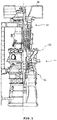
- a gas turbine 1 of a related art includes a compressor 11, a combustor 12, and a turbine 13. Air flowing inside through an air inlet 20 is compressed into high-temperature and high-pressure compressed air by the compressor. High-temperature and high-pressure combustion gas (i.e., working fluid) is produced by combusting the compressed air by supplying fuel to the compressed air in the combustor 12. The turbine 13 is operated by the combustion gas, and a power generator connected to the gas turbine 1 is operated.
- combustion gas i.e., working fluid
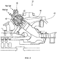
- a combustor 12 of a gas turbine of the related art includes a plurality of main burners 45 disposed around a pilot burner 44.
- a pilot nozzle (not shown) is disposed in the pilot burner 44, and a main nozzle (not shown) is disposed in the main burners 45. Further, the pilot burner 44 and the main burners 45 are arranged to face a combustion chamber 43.
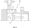
- FIG. 3 is a partial cross-sectional view showing a combustor nozzle assembly according to the related art.
- a combustor nozzle casing 10 of a combustor nozzle assembly of the related art has a flat internal shape, so compressed air does not uniformly flow in a combustor fuel nozzle.
- a separate quaternary nozzle 14 for pre-mixing is provided in the combustor nozzle casing 10 of the related art, so it is required to weld the quaternary nozzle 11.
- the volume and thickness of the combustor nozzle casing 10 are increased due to a fuel chamber 15 that communicates with the quaternary nozzle 14. Therefore, there is a need to develop a combustor nozzle assembly that can solve the problems in the related art.
- An object of the present disclosure is to provide a combustor nozzle assembly having a structure that reduces the volume of a nozzle casing, improves uniformity in flow of compressed air, reduces the manufacturing cost by removing a quaternary nozzle, and improves a pre-mixing effect, and a gas turbine having the combustor nozzle assembly.
- a combustor nozzle assembly includes a nozzle casing for receiving compressed air from a compressor, a curved surface at a corner continuing from an inner surface thereof that is perpendicular to the direction of the compressed air, a fuel spray hole formed at the curved surface, and a fuel chamber having a predetermined volume formed by the curved surface and the surface of the nozzle casing to supply fuel into the nozzle casing through the fuel spray hole.
- the curved surface may be rounded with a predetermined radius of curvature at the corner.
- the radius of curvature may be 10 to 50% of an inner diameter of the nozzle casing.
- the fuel spray hole may be formed to face a center of the radius of curvature.
- Two or more fuel spray holes may be formed along the curved surface, and the fuel spray holes may be arranged in one or more rows.
- Two or more fuel spray holes having different diameters may be arranged in a predetermined pattern at the curved surface.
- the fuel spray holes may include a first fuel spray hole formed at a right center of the curved surface in a vertical cross-section, and a second fuel spray hole formed close to the first fuel spray hole and having a diameter of 10 to 50% of the diameter of the first fuel spray hole.
- Two or more first vortex projections having a predetermined length may be formed on an inner surface of the nozzle casing to generate a vortex of compressed air flowing through a liner.
- the first vortex projections may be spaced at a predetermined angle from each other around the inner surface of the nozzle casing.
- a second vortex projection having a predetermined length is formed on an inner surface of the nozzle casing that is perpendicular to the direction of the compressed air to generate a vortex of compressed air flowing through a liner.
- the second vortex projection may be spirally formed toward a center.
- One or more third vortex projections having a predetermined length may be formed spirally in an inflow direction of compressed air to generate a vortex of compressed air flowing through the liner.
- a gas turbine including a compressor, a combustor nozzle assembly, and a turbine
- the combustor nozzle assembly includes a nozzle casing for receiving compressed air from the compressor, a curved surface formed at a corner continuing from an inner surface of the nozzle casing that is perpendicular to the direction of the compressed air, and a fuel chamber for supplying fuel into the nozzle casing through a fuel spray hole formed at the curved surface.
- the fuel spray hole may be formed to face a center of the radius of curvature.
- Two or more fuel spray holes may be formed around an inner surface of the nozzle casing, and the fuel spray holes may be arranged in one or more rows.
- Two or more fuel spray holes having different diameters may be arranged in a predetermined pattern at the curved surface.
- a nozzle casing, fuel spray holes, and fuel chamber that are formed in a specific structure reduces the volume of a nozzle casing, improves uniformity in flow of compressed air, reduces the manufacturing cost by removing a quaternary nozzle, and improves a pre-mixing effect, and a gas turbine having the combustor nozzle assembly.
- a curved surface and fuel spray holes formed at a corner continuing from an inner surface of the nozzle casing that is perpendicular to the direction of the compressed air, and a fuel chamber improve uniformity in flow of compressed air, reduce the manufacturing cost of a combustor by removing a quaternary nozzle, and improve a pre-mixing effect.
- the fuel spray holes arranged in a specific direction at the curved surface and arranged in a predetermined pattern improve a pre-mixing effect.
- the first fuel spray hole and the second fuel spray hole disposed at predetermined positions improve a pre-mixing effect.
- first vortex projections, a second vortex projection, and third vortex projections that have specific structures improve a pre-mixing effect.
- a gas turbine of the present disclosure including the combustor nozzle assembly having a specific configuration above has low manufacturing cost and improved operational efficiency.
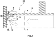
- FIG. 4 is a partial cross-sectional view showing a combustor nozzle assembly according to an exemplary embodiment.
- a combustor nozzle assembly 100 includes a nozzle casing 110 having a curved surface 112 having a specific structure, fuel spray holes 120, and a fuel chamber 130, whereby the volume of the nozzle casing 110 is reduced, uniformity in flow of compressed air is improved, manufacturing cost is reduced by removing a quaternary nozzle, and pre-mixing effect is improved.
- the nozzle casing 110 has a smooth curved surface 112 at a corner continuing from a surface 111 that is generally perpendicular to the direction of compressed air. According to this structure, compressed air can smoothly change a direction and can be more effectively mixed with fuel.
- the curved surface 112 may be rounded having a predetermined radius of curvature R at a corner of the nozzle casing 110.
- the radius of curvature R of the curved surface 112 may be 10 to 50% of the inner diameter ID of the nozzle casing 110, for example, but may be appropriately varied accordingly.
- the fuel injection holes 120 may be formed at the curved surface 112, as shown in FIGS. 4 and 8 to 10 .
- the fuel chamber 130 having a predetermined volume may be formed by the curved surface 112 and the corner walls of the nozzle casing 110.
- the fuel chamber 130 forms a space for keeping a predetermined amount of fuel that is supplied into the nozzle casing 110 through the fuel spray holes 120.
- the directions of the fuel spray holes 120 are formed through the curved surface 112 such that they guide fuel to be appropriately mixed with compressed air.
- the fuel spray holes 120 may be formed to face the center of the radius of curvature of the curved surface 112. This is because fuel is allowed to be substantially perpendicularly sprayed to the flow of compressed air returning from the curved surface 112, which would be advantageous in uniformly mixing the compressed air and the fuel.
- two or more fuel spray holes 120 may be formed at the curved surface 112.
- the fuel spray holes 120 may be formed in one or more rows L1, L2, and L3, as shown in FIG. 9 .
- two or more fuel spray holes 120 having different diameters may be arranged in a specific pattern at the curved surface 112. The pattern of the fuel spray holes 120 are arranged such that compressed air and fuel can be effectively mixed, and it may be appropriately varied accordingly.
- the fuel spray holes 120 may include a first fuel spray hole 121 and a second fuel spray hole 122.
- the first fuel spray hole 121 is formed at the right center of the curved surface 112 in a vertical cross-section.
- the second fuel spray holes 122 is formed close to the first fuel spray hole 121 and has a diameter of 10 to 50% of the diameter of the first fuel spray hole 121. Accordingly, the largest amount of fuel is sprayed at the right center of the curved surface 112 where compressed air most actively flows and a smaller amount of fuel is sprayed around the right center, so fuel and air can be more uniformly mixed.
- the combustor nozzle assembly 100 may further have first vortex projections 141 on the inner side of the nozzle casing 110.
- first vortex projections 141 having a predetermined length may be formed on the inner side of the nozzle casing 110 so that a vortex can be generated in the compressed air flowing through a liner.
- the first vortex projections 141 may be arranged at a predetermined angle from each other along the inner side of the nozzle casing 110. Accordingly, compressed air is turned by the first vortex projections 141, so it can be more effectively mixed with fuel.
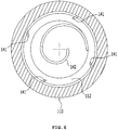
- a second vortex projection 142 may be formed on a portion of the inner side of the nozzle casing 110 that perpendicularly comes in contact with compressed air, as shown in FIG. 6 .
- the second vortex projection 142 may protrude a predetermined distance from the inner side of the nozzle casing 110 so that a vortex can be generated in the compressed air flowing through the liner.
- the second vortex projection 142 may be spirally formed toward the center, as shown in FIG. 6 .
- the second vortex projection 142 allows the compressed air flowing in the nozzle casing 110 to more effectively turn when coming in contact with the compressed air, so it allows the compressed air to be easily mixed with fuel.
- third vortex projections 143 may be formed on the inner surface of the nozzle casing 110.
- the third vortex projections 142 may have a predetermined length and may be formed spirally in the inflow direction of compressed air so that a vortex can be generated in the compressed air flowing through the liner.
- a nozzle casing, fuel spray holes, and fuel chamber having the specific exemplary structures provided reduces the volume of a nozzle casing, improves uniformity in flow of compressed air, reduces the manufacturing cost by removing a quaternary nozzle, and improves a premixing effect, and a gas turbine having the combustor nozzle assembly.
- a curved surface and fuel spray holes formed at a corner continuing from a surface of the inner surface of the nozzle casing with which compressed air perpendicularly comes in contact, and a fuel chamber provided inside the curved surface improve uniformity in flow of compressed air, reduce the manufacturing cost of a combustor by removing a quaternary nozzle, and improve a premixing effect.
- the fuel spray holes arranged in a specific direction at the curved surface and arranged in a predetermined pattern provide a combustor nozzle assembly that improves a pre-mixing effect.
- the first fuel spray hole and the second fuel spray hole disposed at predetermined positions provide a combustor nozzle assembly that improves a pre-mixing effect.
- first vortex projections, a second vortex projection, and third vortex projections that have specific structures provide a combustor nozzle assembly that improves pre-mixing effect.
- the present disclosure provides a gas turbine having the combustor nozzle assembly having a specific configuration as explained above to provide a gas turbine of which the manufacturing cost is low and the operational efficiency is improved.
Landscapes
- Engineering & Computer Science (AREA)
- Chemical & Material Sciences (AREA)
- Combustion & Propulsion (AREA)
- Mechanical Engineering (AREA)
- General Engineering & Computer Science (AREA)
- Spray-Type Burners (AREA)
- Gas Burners (AREA)
Abstract
Description
- The present application claims priority to Korean Patent Application No.
10-2017-0049623, filed April 18, 2017 - The present disclosure relates to a combustor nozzle assembly and a gas turbine having the same and, more particularly, to a combustor nozzle assembly including a structure that improves a pre-mixing effect without a quaternary nozzle, and a gas turbine having the combustor nozzle assembly.
- In general, as shown in
FIG. 1 , a gas turbine 1 of a related art includes acompressor 11, acombustor 12, and aturbine 13. Air flowing inside through anair inlet 20 is compressed into high-temperature and high-pressure compressed air by the compressor. High-temperature and high-pressure combustion gas (i.e., working fluid) is produced by combusting the compressed air by supplying fuel to the compressed air in thecombustor 12. Theturbine 13 is operated by the combustion gas, and a power generator connected to the gas turbine 1 is operated. - As shown in
FIG 2 , acombustor 12 of a gas turbine of the related art includes a plurality ofmain burners 45 disposed around apilot burner 44. A pilot nozzle (not shown) is disposed in thepilot burner 44, and a main nozzle (not shown) is disposed in themain burners 45. Further, thepilot burner 44 and themain burners 45 are arranged to face acombustion chamber 43. -
FIG. 3 is a partial cross-sectional view showing a combustor nozzle assembly according to the related art. According toFIG. 3 , acombustor nozzle casing 10 of a combustor nozzle assembly of the related art has a flat internal shape, so compressed air does not uniformly flow in a combustor fuel nozzle. Further, a separate quaternary nozzle 14 for pre-mixing is provided in thecombustor nozzle casing 10 of the related art, so it is required to weld thequaternary nozzle 11. Further, the volume and thickness of thecombustor nozzle casing 10 are increased due to afuel chamber 15 that communicates with the quaternary nozzle 14. Therefore, there is a need to develop a combustor nozzle assembly that can solve the problems in the related art. - An object of the present disclosure is to provide a combustor nozzle assembly having a structure that reduces the volume of a nozzle casing, improves uniformity in flow of compressed air, reduces the manufacturing cost by removing a quaternary nozzle, and improves a pre-mixing effect, and a gas turbine having the combustor nozzle assembly.
- A combustor nozzle assembly according to an aspect includes a nozzle casing for receiving compressed air from a compressor, a curved surface at a corner continuing from an inner surface thereof that is perpendicular to the direction of the compressed air, a fuel spray hole formed at the curved surface, and a fuel chamber having a predetermined volume formed by the curved surface and the surface of the nozzle casing to supply fuel into the nozzle casing through the fuel spray hole.
- The curved surface may be rounded with a predetermined radius of curvature at the corner.
- The radius of curvature may be 10 to 50% of an inner diameter of the nozzle casing.
- The fuel spray hole may be formed to face a center of the radius of curvature.
- Two or more fuel spray holes may be formed along the curved surface, and the fuel spray holes may be arranged in one or more rows.
- Two or more fuel spray holes having different diameters may be arranged in a predetermined pattern at the curved surface.
- The fuel spray holes may include a first fuel spray hole formed at a right center of the curved surface in a vertical cross-section, and a second fuel spray hole formed close to the first fuel spray hole and having a diameter of 10 to 50% of the diameter of the first fuel spray hole.
- Two or more first vortex projections having a predetermined length may be formed on an inner surface of the nozzle casing to generate a vortex of compressed air flowing through a liner.
- The first vortex projections may be spaced at a predetermined angle from each other around the inner surface of the nozzle casing.
- A second vortex projection having a predetermined length is formed on an inner surface of the nozzle casing that is perpendicular to the direction of the compressed air to generate a vortex of compressed air flowing through a liner.
- The second vortex projection may be spirally formed toward a center.
- One or more third vortex projections having a predetermined length may be formed spirally in an inflow direction of compressed air to generate a vortex of compressed air flowing through the liner.
- Another aspect provides a gas turbine including a compressor, a combustor nozzle assembly, and a turbine, in which the combustor nozzle assembly includes a nozzle casing for receiving compressed air from the compressor, a curved surface formed at a corner continuing from an inner surface of the nozzle casing that is perpendicular to the direction of the compressed air, and a fuel chamber for supplying fuel into the nozzle casing through a fuel spray hole formed at the curved surface.
- The fuel spray hole may be formed to face a center of the radius of curvature.
- Two or more fuel spray holes may be formed around an inner surface of the nozzle casing, and the fuel spray holes may be arranged in one or more rows.
- Two or more fuel spray holes having different diameters may be arranged in a predetermined pattern at the curved surface.
- As described above, according to the combustor nozzle assembly of the present disclosure, a nozzle casing, fuel spray holes, and fuel chamber that are formed in a specific structure reduces the volume of a nozzle casing, improves uniformity in flow of compressed air, reduces the manufacturing cost by removing a quaternary nozzle, and improves a pre-mixing effect, and a gas turbine having the combustor nozzle assembly.
- Further, according to the combustor nozzle assembly of the present disclosure, a curved surface and fuel spray holes formed at a corner continuing from an inner surface of the nozzle casing that is perpendicular to the direction of the compressed air, and a fuel chamber improve uniformity in flow of compressed air, reduce the manufacturing cost of a combustor by removing a quaternary nozzle, and improve a pre-mixing effect.
- Further, according to the combustor nozzle assembly of the present disclosure, the fuel spray holes arranged in a specific direction at the curved surface and arranged in a predetermined pattern improve a pre-mixing effect.
- Further, according to the combustor nozzle assembly of the present disclosure, the first fuel spray hole and the second fuel spray hole disposed at predetermined positions improve a pre-mixing effect.
- Further, according to the combustor nozzle assembly of the present disclosure, first vortex projections, a second vortex projection, and third vortex projections that have specific structures improve a pre-mixing effect.
- Therefore, a gas turbine of the present disclosure including the combustor nozzle assembly having a specific configuration above has low manufacturing cost and improved operational efficiency.
- The above and other objects, features and other advantages of the present disclosure will be more clearly understood from the following detailed description when taken in conjunction with the accompanying drawings, in which:
-
FIG. 1 is a cross-sectional view showing a gas turbine according to a related art; -
FIG. 2 is a partial cross-sectional view showing the combustor shown inFIG. 1 ; -
FIG. 3 is a partial cross-sectional view showing a combustor nozzle assembly according to the related art; -
FIG. 4 is a partial cross-sectional view showing a combustor nozzle assembly according to an exemplary embodiment; -
FIG. 5 is a cross-sectional view taken along line A-A' ofFIG. 4 ; -
FIG. 6 is a view showing another exemplary embodiment ofFIG. 5 ; -
FIG. 7 is a cross-sectional view showing the inner side of a nozzle casing of a combustor nozzle assembly according to another exemplary embodiment; -
FIG. 8 is a perspective view showing a portion of the combustor nozzle assembly according to an exemplary embodiment; -
FIG. 9 is a perspective view showing a portion of a combustor nozzle assembly according to another exemplary embodiment; and -
FIG. 10 is an enlarged view of the portion B inFIG. 4 . - Hereinafter, exemplary embodiments of the present disclosure are described in detail with reference to the drawings. The terms and words used in the present specification and claims should not be interpreted as being limited to typical meanings or dictionary definitions, but should be interpreted as having meanings and concepts relevant to the technical scope of the present disclosure.
- It should be understood that when an element is referred to as being "on" another element, the elements may be in contact with each other or there may be an intervening element present. Through the present specification, unless explicitly described otherwise, "comprising" any components will be understood to imply the inclusion of other components rather than the exclusion of any other components.
-
FIG. 4 is a partial cross-sectional view showing a combustor nozzle assembly according to an exemplary embodiment. As shown inFIG. 4 , acombustor nozzle assembly 100 includes anozzle casing 110 having acurved surface 112 having a specific structure,fuel spray holes 120, and afuel chamber 130, whereby the volume of thenozzle casing 110 is reduced, uniformity in flow of compressed air is improved, manufacturing cost is reduced by removing a quaternary nozzle, and pre-mixing effect is improved. - The components of the
combustor nozzle assembly 100 according to the exemplary embodiment are described hereafter in detail with reference to the drawings. - The
nozzle casing 110 according to the exemplary embodiment has a smoothcurved surface 112 at a corner continuing from asurface 111 that is generally perpendicular to the direction of compressed air. According to this structure, compressed air can smoothly change a direction and can be more effectively mixed with fuel. - In detail, the
curved surface 112 may be rounded having a predetermined radius of curvature R at a corner of thenozzle casing 110. The radius of curvature R of thecurved surface 112 may be 10 to 50% of the inner diameter ID of thenozzle casing 110, for example, but may be appropriately varied accordingly. - The
fuel injection holes 120 according to the exemplary embodiment may be formed at thecurved surface 112, as shown inFIGS. 4 and8 to 10 . - The
fuel chamber 130 having a predetermined volume may be formed by thecurved surface 112 and the corner walls of thenozzle casing 110. Thefuel chamber 130 forms a space for keeping a predetermined amount of fuel that is supplied into thenozzle casing 110 through the fuel spray holes 120. - The directions of the fuel spray holes 120 are formed through the
curved surface 112 such that they guide fuel to be appropriately mixed with compressed air. For example, as shown inFIG. 10 , the fuel spray holes 120 may be formed to face the center of the radius of curvature of thecurved surface 112. This is because fuel is allowed to be substantially perpendicularly sprayed to the flow of compressed air returning from thecurved surface 112, which would be advantageous in uniformly mixing the compressed air and the fuel. - As shown in
FIGS. 8 and9 , two or more fuel spray holes 120 according to the exemplary embodiments may be formed at thecurved surface 112. The fuel spray holes 120 may be formed in one or more rows L1, L2, and L3, as shown inFIG. 9 . Further, two or more fuel spray holes 120 having different diameters may be arranged in a specific pattern at thecurved surface 112. The pattern of the fuel spray holes 120 are arranged such that compressed air and fuel can be effectively mixed, and it may be appropriately varied accordingly. - In detail, as shown in
FIG. 9 , the fuel spray holes 120 according to the exemplary embodiment may include a firstfuel spray hole 121 and a secondfuel spray hole 122. - The first
fuel spray hole 121 is formed at the right center of thecurved surface 112 in a vertical cross-section. The second fuel spray holes 122 is formed close to the firstfuel spray hole 121 and has a diameter of 10 to 50% of the diameter of the firstfuel spray hole 121. Accordingly, the largest amount of fuel is sprayed at the right center of thecurved surface 112 where compressed air most actively flows and a smaller amount of fuel is sprayed around the right center, so fuel and air can be more uniformly mixed. - Meanwhile, as shown in
FIG. 6 , thecombustor nozzle assembly 100 according to the exemplary embodiment may further havefirst vortex projections 141 on the inner side of thenozzle casing 110. In detail, two or morefirst vortex projections 141 having a predetermined length may be formed on the inner side of thenozzle casing 110 so that a vortex can be generated in the compressed air flowing through a liner. Thefirst vortex projections 141 may be arranged at a predetermined angle from each other along the inner side of thenozzle casing 110. Accordingly, compressed air is turned by thefirst vortex projections 141, so it can be more effectively mixed with fuel. - According to another exemplary embodiment, a
second vortex projection 142 may be formed on a portion of the inner side of thenozzle casing 110 that perpendicularly comes in contact with compressed air, as shown inFIG. 6 . In detail, thesecond vortex projection 142 may protrude a predetermined distance from the inner side of thenozzle casing 110 so that a vortex can be generated in the compressed air flowing through the liner. Thesecond vortex projection 142 may be spirally formed toward the center, as shown inFIG. 6 . Thesecond vortex projection 142 allows the compressed air flowing in thenozzle casing 110 to more effectively turn when coming in contact with the compressed air, so it allows the compressed air to be easily mixed with fuel. - Further, as shown in
Fig. 7 ,third vortex projections 143 may be formed on the inner surface of thenozzle casing 110. In detail, thethird vortex projections 142 may have a predetermined length and may be formed spirally in the inflow direction of compressed air so that a vortex can be generated in the compressed air flowing through the liner. - As described above, according to the combustor nozzle assembly of the present disclosure, a nozzle casing, fuel spray holes, and fuel chamber having the specific exemplary structures provided reduces the volume of a nozzle casing, improves uniformity in flow of compressed air, reduces the manufacturing cost by removing a quaternary nozzle, and improves a premixing effect, and a gas turbine having the combustor nozzle assembly.
- Further, according to the combustor nozzle assembly of the present disclosure, a curved surface and fuel spray holes formed at a corner continuing from a surface of the inner surface of the nozzle casing with which compressed air perpendicularly comes in contact, and a fuel chamber provided inside the curved surface improve uniformity in flow of compressed air, reduce the manufacturing cost of a combustor by removing a quaternary nozzle, and improve a premixing effect.
- Further, according to the combustor nozzle assembly of the present disclosure, the fuel spray holes arranged in a specific direction at the curved surface and arranged in a predetermined pattern provide a combustor nozzle assembly that improves a pre-mixing effect.
- Further, according to the combustor nozzle assembly of the present disclosure, the first fuel spray hole and the second fuel spray hole disposed at predetermined positions provide a combustor nozzle assembly that improves a pre-mixing effect.
- Further, according to the combustor nozzle assembly of the present disclosure, first vortex projections, a second vortex projection, and third vortex projections that have specific structures provide a combustor nozzle assembly that improves pre-mixing effect.
- Further, the present disclosure provides a gas turbine having the combustor nozzle assembly having a specific configuration as explained above to provide a gas turbine of which the manufacturing cost is low and the operational efficiency is improved.
- Specific exemplary embodiments of the present disclosure are described above. However, it should understood that the present disclosure is not limited to the specific exemplary embodiments and all modifications, equivalents, and substitutions should be construed as being included in the scope of the present disclosure as defined in the claims.
- That is, the present disclosure is not limited to the specific exemplary embodiments described above, but various modifications may be made without departing from the scope of the present disclosure as defined in claims.
Claims (14)
- A combustor nozzle assembly (100), comprising:a nozzle casing (110) for receiving compressed air from a compressor (11);a curved surface (112) at a corner continuing from an inner surface of the nozzle casing (111) that is perpendicular to the direction of the compressed air, the curved surface (112) including a fuel spray hole (120); anda fuel chamber (130) formed by the curved surface (112) and the nozzle casing (110) to supply fuel into the nozzle casing (110) through the fuel spray hole (120).
- The assembly (100) of claim 1, wherein the curved surface (112) is rounded with a predetermined radius.
- The assembly (100) of claim 2, wherein the fuel spray hole (120) is formed to face the center of the radius of curvature.
- The assembly (100) according to any one of the preceding claims, wherein two or more fuel spray holes (120) are formed along the curved surface (112) and the fuel spray holes (120) are arranged in one or more rows.
- The assembly (100) according to any one of the preceding claims, wherein two or more fuel spray holes (120) having different diameters are arranged in a predetermined pattern on the curved surface (112).
- The assembly (100) according to any one of the preceding claims, wherein the fuel spray holes (120) include
a first fuel spray hole (121) formed at a right center of the curved surface (112) in a vertical cross-section. - The assembly (100) of claim 6, wherein the fuel spray holes (120) include
a second fuel spray hole (122) formed close to the first fuel spray hole (121) and having a diameter of 10 to 50% of the diameter of the first fuel spray hole (121). - The assembly (100) according to any one of the preceding claims, wherein the nozzle casing (110) includes two or more first vortex projections (141) having a predetermined length to generate a vortex of compressed air.
- The assembly (100) of claim 8, wherein the first vortex projections (141) are spaced at a predetermined angle from each other around the inner surface of the nozzle casing (110).
- The assembly (100) according to any one of the preceding claims, wherein the nozzle casing (110) includes a second vortex projection (142) having a predetermined length formed on the inner surface of the nozzle casing (111) that is perpendicular to the direction of the compressed air to generate a vortex of compressed air.
- The assembly (100) of claim 10, wherein the second vortex projection (142) is spirally formed toward a center.
- The assembly (100) according to any one of the preceding claims, wherein the nozzle casing (110) includes one or more third vortex projections (143) having a predetermined length and formed spirally in a inflow direction of the compressed air to generate a vortex of compressed air.
- The assembly (100) according to any one of the preceding claims, wherein the fuel chamber (130) has a predetermined volume.
- A gas turbine (1), comprising:a compressor (11),the combustor nozzle assembly (100) according to any one of the preceding claims, anda turbine (13).
Applications Claiming Priority (1)
| Application Number | Priority Date | Filing Date | Title |
|---|---|---|---|
| KR1020170049623A KR101889542B1 (en) | 2017-04-18 | 2017-04-18 | Combustor Nozzle Assembly And Gas Turbine Having The Same |
Publications (2)
| Publication Number | Publication Date |
|---|---|
| EP3392570A1 true EP3392570A1 (en) | 2018-10-24 |
| EP3392570B1 EP3392570B1 (en) | 2019-08-21 |
Family
ID=59966637
Family Applications (1)
| Application Number | Title | Priority Date | Filing Date |
|---|---|---|---|
| EP17192888.0A Active EP3392570B1 (en) | 2017-04-18 | 2017-09-25 | Combustor nozzle assembly and gas turbine having the same |
Country Status (4)
| Country | Link |
|---|---|
| US (1) | US11015810B2 (en) |
| EP (1) | EP3392570B1 (en) |
| JP (1) | JP6458838B2 (en) |
| KR (1) | KR101889542B1 (en) |
Families Citing this family (1)
| Publication number | Priority date | Publication date | Assignee | Title |
|---|---|---|---|---|
| JP7118836B2 (en) | 2018-09-25 | 2022-08-16 | フォルシアクラリオン・エレクトロニクス株式会社 | Line recognition device |
Citations (4)
| Publication number | Priority date | Publication date | Assignee | Title |
|---|---|---|---|---|
| DE3819898A1 (en) * | 1988-06-11 | 1989-12-14 | Daimler Benz Ag | Combustion chamber for a thermal turbo-engine |
| JPH09184629A (en) * | 1996-01-04 | 1997-07-15 | Hitachi Ltd | Gas turbine combustor premixer |
| JP2009192175A (en) * | 2008-02-15 | 2009-08-27 | Mitsubishi Heavy Ind Ltd | Combustor |
| US20120111012A1 (en) * | 2010-11-09 | 2012-05-10 | Opra Technologies B.V. | Ultra low emissions gas turbine combustor |
Family Cites Families (23)
| Publication number | Priority date | Publication date | Assignee | Title |
|---|---|---|---|---|
| JPS61208419A (en) * | 1985-03-12 | 1986-09-16 | Mitsubishi Heavy Ind Ltd | Pre-mix nozzle for gas turbine combustor |
| US5251447A (en) * | 1992-10-01 | 1993-10-12 | General Electric Company | Air fuel mixer for gas turbine combustor |
| JPH06272862A (en) * | 1993-03-18 | 1994-09-27 | Hitachi Ltd | Method and apparatus for mixing fuel into air |
| JP3192055B2 (en) * | 1994-11-08 | 2001-07-23 | 株式会社日立製作所 | Gas turbine combustor |
| US5899075A (en) * | 1997-03-17 | 1999-05-04 | General Electric Company | Turbine engine combustor with fuel-air mixer |
| US6176087B1 (en) * | 1997-12-15 | 2001-01-23 | United Technologies Corporation | Bluff body premixing fuel injector and method for premixing fuel and air |
| US8266911B2 (en) * | 2005-11-14 | 2012-09-18 | General Electric Company | Premixing device for low emission combustion process |
| US7832212B2 (en) * | 2006-11-10 | 2010-11-16 | General Electric Company | High expansion fuel injection slot jet and method for enhancing mixing in premixing devices |
| US8161750B2 (en) * | 2009-01-16 | 2012-04-24 | General Electric Company | Fuel nozzle for a turbomachine |
| EP2299091A1 (en) * | 2009-09-07 | 2011-03-23 | Alstom Technology Ltd | Method for Switching over a Gas Turbine Burner Operation from Liquid to Gas Fuel and Vice-Versa |
| US20110131998A1 (en) * | 2009-12-08 | 2011-06-09 | Vaibhav Nadkarni | Fuel injection in secondary fuel nozzle |
| KR101470774B1 (en) | 2011-03-30 | 2014-12-08 | 미츠비시 쥬고교 가부시키가이샤 | Nozzle, gas turbine combustor and gas turbine |
| US9188063B2 (en) * | 2011-11-03 | 2015-11-17 | Delavan Inc. | Injectors for multipoint injection |
| JP6154988B2 (en) * | 2012-01-05 | 2017-06-28 | 三菱日立パワーシステムズ株式会社 | Combustor |
| US20130180248A1 (en) * | 2012-01-18 | 2013-07-18 | Nishant Govindbhai Parsania | Combustor Nozzle/Premixer with Curved Sections |
| US8943833B2 (en) * | 2012-07-06 | 2015-02-03 | United Technologies Corporation | Fuel flexible fuel injector |
| US9212823B2 (en) * | 2012-09-06 | 2015-12-15 | General Electric Company | Systems and methods for suppressing combustion driven pressure fluctuations with a premix combustor having multiple premix times |
| US9217373B2 (en) * | 2013-02-27 | 2015-12-22 | General Electric Company | Fuel nozzle for reducing modal coupling of combustion dynamics |
| KR101579122B1 (en) | 2014-01-15 | 2015-12-21 | 두산중공업 주식회사 | Combuster of gas turbine, gasturbineincluding the same, and cooling method thereof |
| US9423133B2 (en) * | 2014-05-08 | 2016-08-23 | FGC Plasms Solutions LLC | Method and apparatus for assisting with the combustion of fuel |
| EP3026347A1 (en) * | 2014-11-25 | 2016-06-01 | Alstom Technology Ltd | Combustor with annular bluff body |
| JP6423760B2 (en) | 2015-06-24 | 2018-11-14 | 三菱日立パワーシステムズ株式会社 | Fuel nozzle structure of gas turbine combustor |
| JP6647924B2 (en) * | 2016-03-07 | 2020-02-14 | 三菱重工業株式会社 | Gas turbine combustor and gas turbine |
-
2017
- 2017-04-18 KR KR1020170049623A patent/KR101889542B1/en active Active
- 2017-09-20 JP JP2017180665A patent/JP6458838B2/en active Active
- 2017-09-25 US US15/714,800 patent/US11015810B2/en active Active
- 2017-09-25 EP EP17192888.0A patent/EP3392570B1/en active Active
Patent Citations (4)
| Publication number | Priority date | Publication date | Assignee | Title |
|---|---|---|---|---|
| DE3819898A1 (en) * | 1988-06-11 | 1989-12-14 | Daimler Benz Ag | Combustion chamber for a thermal turbo-engine |
| JPH09184629A (en) * | 1996-01-04 | 1997-07-15 | Hitachi Ltd | Gas turbine combustor premixer |
| JP2009192175A (en) * | 2008-02-15 | 2009-08-27 | Mitsubishi Heavy Ind Ltd | Combustor |
| US20120111012A1 (en) * | 2010-11-09 | 2012-05-10 | Opra Technologies B.V. | Ultra low emissions gas turbine combustor |
Also Published As
| Publication number | Publication date |
|---|---|
| US20180299130A1 (en) | 2018-10-18 |
| KR101889542B1 (en) | 2018-08-17 |
| JP6458838B2 (en) | 2019-01-30 |
| EP3392570B1 (en) | 2019-08-21 |
| US11015810B2 (en) | 2021-05-25 |
| JP2018179483A (en) | 2018-11-15 |
Similar Documents
| Publication | Publication Date | Title |
|---|---|---|
| CN206973615U (en) | Guide's pre-mixing nozzle and fuel nozzle assembly | |
| US9939158B2 (en) | Combustor with ring part having protrusions and gas turbine including the combustor | |
| US20140033718A1 (en) | Combustor | |
| KR101493256B1 (en) | Gasturbine burner | |
| CN107923620B (en) | System and method for multi-fuel premixing nozzle with integral liquid injector/evaporator | |
| JP6228434B2 (en) | Gas turbine combustor | |
| CN206973617U (en) | Guide's pre-mixing nozzle and fuel nozzle assembly | |
| EP3425279B1 (en) | Gas turbine combustor including fuel nozzle assembly | |
| CN102155738A (en) | Apparatus and method for supplying fuel | |
| US10240795B2 (en) | Pilot burner having burner face with radially offset recess | |
| JP2010060189A (en) | Burner, and method for supplying fuel and method for modifying fuel nozzle in burner | |
| JPH06272862A (en) | Method and apparatus for mixing fuel into air | |
| KR20180114204A (en) | Gas turbine | |
| KR102116903B1 (en) | Swirler assembly | |
| KR102236267B1 (en) | Industrial Aombustor | |
| US11221142B2 (en) | Fuel nozzle assembly and gas turbine having the same | |
| US8291705B2 (en) | Ultra low injection angle fuel holes in a combustor fuel nozzle | |
| KR102050563B1 (en) | Combustor and gas turbine comprising the same | |
| EP3392570B1 (en) | Combustor nozzle assembly and gas turbine having the same | |
| CN107101224B (en) | Single-tube combustion chamber and gas turbine | |
| KR20170003052A (en) | A combustor including a fluid guide | |
| JP2015072077A (en) | Gas turbine combustor | |
| CN206861596U (en) | A kind of can burner and gas turbine | |
| JP2010159953A (en) | Fuel plenum vortex breaker | |
| KR102847658B1 (en) | Nozzle for gas turbine combustor |
Legal Events
| Date | Code | Title | Description |
|---|---|---|---|
| PUAI | Public reference made under article 153(3) epc to a published international application that has entered the european phase |
Free format text: ORIGINAL CODE: 0009012 |
|
| STAA | Information on the status of an ep patent application or granted ep patent |
Free format text: STATUS: REQUEST FOR EXAMINATION WAS MADE |
|
| 17P | Request for examination filed |
Effective date: 20170925 |
|
| AK | Designated contracting states |
Kind code of ref document: A1 Designated state(s): AL AT BE BG CH CY CZ DE DK EE ES FI FR GB GR HR HU IE IS IT LI LT LU LV MC MK MT NL NO PL PT RO RS SE SI SK SM TR |
|
| AX | Request for extension of the european patent |
Extension state: BA ME |
|
| GRAP | Despatch of communication of intention to grant a patent |
Free format text: ORIGINAL CODE: EPIDOSNIGR1 |
|
| STAA | Information on the status of an ep patent application or granted ep patent |
Free format text: STATUS: GRANT OF PATENT IS INTENDED |
|
| RBV | Designated contracting states (corrected) |
Designated state(s): AL AT BE BG CH CY CZ DE DK EE ES FI FR GB GR HR HU IE IS IT LI LT LU LV MC MK MT NL NO PL PT RO RS SE SI SK SM TR |
|
| RIC1 | Information provided on ipc code assigned before grant |
Ipc: F23R 3/28 20060101AFI20190320BHEP |
|
| INTG | Intention to grant announced |
Effective date: 20190408 |
|
| RAP1 | Party data changed (applicant data changed or rights of an application transferred) |
Owner name: DOOSAN HEAVY INDUSTRIES & CONSTRUCTION CO., LTD. |
|
| GRAS | Grant fee paid |
Free format text: ORIGINAL CODE: EPIDOSNIGR3 |
|
| GRAA | (expected) grant |
Free format text: ORIGINAL CODE: 0009210 |
|
| STAA | Information on the status of an ep patent application or granted ep patent |
Free format text: STATUS: THE PATENT HAS BEEN GRANTED |
|
| AK | Designated contracting states |
Kind code of ref document: B1 Designated state(s): AL AT BE BG CH CY CZ DE DK EE ES FI FR GB GR HR HU IE IS IT LI LT LU LV MC MK MT NL NO PL PT RO RS SE SI SK SM TR |
|
| REG | Reference to a national code |
Ref country code: GB Ref legal event code: FG4D |
|
| REG | Reference to a national code |
Ref country code: CH Ref legal event code: EP |
|
| REG | Reference to a national code |
Ref country code: DE Ref legal event code: R096 Ref document number: 602017006308 Country of ref document: DE |
|
| REG | Reference to a national code |
Ref country code: AT Ref legal event code: REF Ref document number: 1170194 Country of ref document: AT Kind code of ref document: T Effective date: 20190915 |
|
| REG | Reference to a national code |
Ref country code: IE Ref legal event code: FG4D |
|
| REG | Reference to a national code |
Ref country code: LT Ref legal event code: MG4D |
|
| REG | Reference to a national code |
Ref country code: NL Ref legal event code: MP Effective date: 20190821 |
|
| PG25 | Lapsed in a contracting state [announced via postgrant information from national office to epo] |
Ref country code: NO Free format text: LAPSE BECAUSE OF FAILURE TO SUBMIT A TRANSLATION OF THE DESCRIPTION OR TO PAY THE FEE WITHIN THE PRESCRIBED TIME-LIMIT Effective date: 20191121 Ref country code: BG Free format text: LAPSE BECAUSE OF FAILURE TO SUBMIT A TRANSLATION OF THE DESCRIPTION OR TO PAY THE FEE WITHIN THE PRESCRIBED TIME-LIMIT Effective date: 20191121 Ref country code: NL Free format text: LAPSE BECAUSE OF FAILURE TO SUBMIT A TRANSLATION OF THE DESCRIPTION OR TO PAY THE FEE WITHIN THE PRESCRIBED TIME-LIMIT Effective date: 20190821 Ref country code: SE Free format text: LAPSE BECAUSE OF FAILURE TO SUBMIT A TRANSLATION OF THE DESCRIPTION OR TO PAY THE FEE WITHIN THE PRESCRIBED TIME-LIMIT Effective date: 20190821 Ref country code: FI Free format text: LAPSE BECAUSE OF FAILURE TO SUBMIT A TRANSLATION OF THE DESCRIPTION OR TO PAY THE FEE WITHIN THE PRESCRIBED TIME-LIMIT Effective date: 20190821 Ref country code: LT Free format text: LAPSE BECAUSE OF FAILURE TO SUBMIT A TRANSLATION OF THE DESCRIPTION OR TO PAY THE FEE WITHIN THE PRESCRIBED TIME-LIMIT Effective date: 20190821 Ref country code: HR Free format text: LAPSE BECAUSE OF FAILURE TO SUBMIT A TRANSLATION OF THE DESCRIPTION OR TO PAY THE FEE WITHIN THE PRESCRIBED TIME-LIMIT Effective date: 20190821 Ref country code: PT Free format text: LAPSE BECAUSE OF FAILURE TO SUBMIT A TRANSLATION OF THE DESCRIPTION OR TO PAY THE FEE WITHIN THE PRESCRIBED TIME-LIMIT Effective date: 20191223 |
|
| PG25 | Lapsed in a contracting state [announced via postgrant information from national office to epo] |
Ref country code: GR Free format text: LAPSE BECAUSE OF FAILURE TO SUBMIT A TRANSLATION OF THE DESCRIPTION OR TO PAY THE FEE WITHIN THE PRESCRIBED TIME-LIMIT Effective date: 20191122 Ref country code: ES Free format text: LAPSE BECAUSE OF FAILURE TO SUBMIT A TRANSLATION OF THE DESCRIPTION OR TO PAY THE FEE WITHIN THE PRESCRIBED TIME-LIMIT Effective date: 20190821 Ref country code: IS Free format text: LAPSE BECAUSE OF FAILURE TO SUBMIT A TRANSLATION OF THE DESCRIPTION OR TO PAY THE FEE WITHIN THE PRESCRIBED TIME-LIMIT Effective date: 20191221 Ref country code: RS Free format text: LAPSE BECAUSE OF FAILURE TO SUBMIT A TRANSLATION OF THE DESCRIPTION OR TO PAY THE FEE WITHIN THE PRESCRIBED TIME-LIMIT Effective date: 20190821 Ref country code: LV Free format text: LAPSE BECAUSE OF FAILURE TO SUBMIT A TRANSLATION OF THE DESCRIPTION OR TO PAY THE FEE WITHIN THE PRESCRIBED TIME-LIMIT Effective date: 20190821 Ref country code: AL Free format text: LAPSE BECAUSE OF FAILURE TO SUBMIT A TRANSLATION OF THE DESCRIPTION OR TO PAY THE FEE WITHIN THE PRESCRIBED TIME-LIMIT Effective date: 20190821 |
|
| REG | Reference to a national code |
Ref country code: AT Ref legal event code: MK05 Ref document number: 1170194 Country of ref document: AT Kind code of ref document: T Effective date: 20190821 |
|
| PG25 | Lapsed in a contracting state [announced via postgrant information from national office to epo] |
Ref country code: TR Free format text: LAPSE BECAUSE OF FAILURE TO SUBMIT A TRANSLATION OF THE DESCRIPTION OR TO PAY THE FEE WITHIN THE PRESCRIBED TIME-LIMIT Effective date: 20190821 |
|
| PG25 | Lapsed in a contracting state [announced via postgrant information from national office to epo] |
Ref country code: PL Free format text: LAPSE BECAUSE OF FAILURE TO SUBMIT A TRANSLATION OF THE DESCRIPTION OR TO PAY THE FEE WITHIN THE PRESCRIBED TIME-LIMIT Effective date: 20190821 Ref country code: AT Free format text: LAPSE BECAUSE OF FAILURE TO SUBMIT A TRANSLATION OF THE DESCRIPTION OR TO PAY THE FEE WITHIN THE PRESCRIBED TIME-LIMIT Effective date: 20190821 Ref country code: DK Free format text: LAPSE BECAUSE OF FAILURE TO SUBMIT A TRANSLATION OF THE DESCRIPTION OR TO PAY THE FEE WITHIN THE PRESCRIBED TIME-LIMIT Effective date: 20190821 Ref country code: IT Free format text: LAPSE BECAUSE OF FAILURE TO SUBMIT A TRANSLATION OF THE DESCRIPTION OR TO PAY THE FEE WITHIN THE PRESCRIBED TIME-LIMIT Effective date: 20190821 Ref country code: RO Free format text: LAPSE BECAUSE OF FAILURE TO SUBMIT A TRANSLATION OF THE DESCRIPTION OR TO PAY THE FEE WITHIN THE PRESCRIBED TIME-LIMIT Effective date: 20190821 Ref country code: EE Free format text: LAPSE BECAUSE OF FAILURE TO SUBMIT A TRANSLATION OF THE DESCRIPTION OR TO PAY THE FEE WITHIN THE PRESCRIBED TIME-LIMIT Effective date: 20190821 |
|
| PG25 | Lapsed in a contracting state [announced via postgrant information from national office to epo] |
Ref country code: CZ Free format text: LAPSE BECAUSE OF FAILURE TO SUBMIT A TRANSLATION OF THE DESCRIPTION OR TO PAY THE FEE WITHIN THE PRESCRIBED TIME-LIMIT Effective date: 20190821 Ref country code: SK Free format text: LAPSE BECAUSE OF FAILURE TO SUBMIT A TRANSLATION OF THE DESCRIPTION OR TO PAY THE FEE WITHIN THE PRESCRIBED TIME-LIMIT Effective date: 20190821 Ref country code: SM Free format text: LAPSE BECAUSE OF FAILURE TO SUBMIT A TRANSLATION OF THE DESCRIPTION OR TO PAY THE FEE WITHIN THE PRESCRIBED TIME-LIMIT Effective date: 20190821 Ref country code: IS Free format text: LAPSE BECAUSE OF FAILURE TO SUBMIT A TRANSLATION OF THE DESCRIPTION OR TO PAY THE FEE WITHIN THE PRESCRIBED TIME-LIMIT Effective date: 20200224 Ref country code: MC Free format text: LAPSE BECAUSE OF FAILURE TO SUBMIT A TRANSLATION OF THE DESCRIPTION OR TO PAY THE FEE WITHIN THE PRESCRIBED TIME-LIMIT Effective date: 20190821 |
|
| REG | Reference to a national code |
Ref country code: DE Ref legal event code: R097 Ref document number: 602017006308 Country of ref document: DE |
|
| PLBE | No opposition filed within time limit |
Free format text: ORIGINAL CODE: 0009261 |
|
| STAA | Information on the status of an ep patent application or granted ep patent |
Free format text: STATUS: NO OPPOSITION FILED WITHIN TIME LIMIT |
|
| PG2D | Information on lapse in contracting state deleted |
Ref country code: IS |
|
| PG25 | Lapsed in a contracting state [announced via postgrant information from national office to epo] |
Ref country code: IE Free format text: LAPSE BECAUSE OF NON-PAYMENT OF DUE FEES Effective date: 20190925 Ref country code: LU Free format text: LAPSE BECAUSE OF NON-PAYMENT OF DUE FEES Effective date: 20190925 |
|
| REG | Reference to a national code |
Ref country code: BE Ref legal event code: MM Effective date: 20190930 |
|
| 26N | No opposition filed |
Effective date: 20200603 |
|
| PG25 | Lapsed in a contracting state [announced via postgrant information from national office to epo] |
Ref country code: BE Free format text: LAPSE BECAUSE OF NON-PAYMENT OF DUE FEES Effective date: 20190930 |
|
| PG25 | Lapsed in a contracting state [announced via postgrant information from national office to epo] |
Ref country code: FR Free format text: LAPSE BECAUSE OF NON-PAYMENT OF DUE FEES Effective date: 20191021 |
|
| REG | Reference to a national code |
Ref country code: CH Ref legal event code: PL |
|
| PG25 | Lapsed in a contracting state [announced via postgrant information from national office to epo] |
Ref country code: CY Free format text: LAPSE BECAUSE OF FAILURE TO SUBMIT A TRANSLATION OF THE DESCRIPTION OR TO PAY THE FEE WITHIN THE PRESCRIBED TIME-LIMIT Effective date: 20190821 |
|
| PG25 | Lapsed in a contracting state [announced via postgrant information from national office to epo] |
Ref country code: MT Free format text: LAPSE BECAUSE OF FAILURE TO SUBMIT A TRANSLATION OF THE DESCRIPTION OR TO PAY THE FEE WITHIN THE PRESCRIBED TIME-LIMIT Effective date: 20190821 Ref country code: HU Free format text: LAPSE BECAUSE OF FAILURE TO SUBMIT A TRANSLATION OF THE DESCRIPTION OR TO PAY THE FEE WITHIN THE PRESCRIBED TIME-LIMIT; INVALID AB INITIO Effective date: 20170925 |
|
| PG25 | Lapsed in a contracting state [announced via postgrant information from national office to epo] |
Ref country code: LI Free format text: LAPSE BECAUSE OF NON-PAYMENT OF DUE FEES Effective date: 20200930 Ref country code: CH Free format text: LAPSE BECAUSE OF NON-PAYMENT OF DUE FEES Effective date: 20200930 |
|
| PG25 | Lapsed in a contracting state [announced via postgrant information from national office to epo] |
Ref country code: SI Free format text: LAPSE BECAUSE OF FAILURE TO SUBMIT A TRANSLATION OF THE DESCRIPTION OR TO PAY THE FEE WITHIN THE PRESCRIBED TIME-LIMIT Effective date: 20190821 |
|
| GBPC | Gb: european patent ceased through non-payment of renewal fee |
Effective date: 20210925 |
|
| PG25 | Lapsed in a contracting state [announced via postgrant information from national office to epo] |
Ref country code: MK Free format text: LAPSE BECAUSE OF FAILURE TO SUBMIT A TRANSLATION OF THE DESCRIPTION OR TO PAY THE FEE WITHIN THE PRESCRIBED TIME-LIMIT Effective date: 20190821 |
|
| PG25 | Lapsed in a contracting state [announced via postgrant information from national office to epo] |
Ref country code: GB Free format text: LAPSE BECAUSE OF NON-PAYMENT OF DUE FEES Effective date: 20210925 |
|
| PGFP | Annual fee paid to national office [announced via postgrant information from national office to epo] |
Ref country code: DE Payment date: 20250702 Year of fee payment: 9 |