EP3392569A1 - Fuel nozzle assembly with a flow guide assembly and a gas turbine - Google Patents
Fuel nozzle assembly with a flow guide assembly and a gas turbine Download PDFInfo
- Publication number
- EP3392569A1 EP3392569A1 EP17193079.5A EP17193079A EP3392569A1 EP 3392569 A1 EP3392569 A1 EP 3392569A1 EP 17193079 A EP17193079 A EP 17193079A EP 3392569 A1 EP3392569 A1 EP 3392569A1
- Authority
- EP
- European Patent Office
- Prior art keywords
- fuel nozzle
- nozzle assembly
- nozzle body
- flow guides
- gas turbine
- Prior art date
- Legal status (The legal status is an assumption and is not a legal conclusion. Google has not performed a legal analysis and makes no representation as to the accuracy of the status listed.)
- Granted
Links
Images



Classifications
-
- F—MECHANICAL ENGINEERING; LIGHTING; HEATING; WEAPONS; BLASTING
- F23—COMBUSTION APPARATUS; COMBUSTION PROCESSES
- F23R—GENERATING COMBUSTION PRODUCTS OF HIGH PRESSURE OR HIGH VELOCITY, e.g. GAS-TURBINE COMBUSTION CHAMBERS
- F23R3/00—Continuous combustion chambers using liquid or gaseous fuel
- F23R3/28—Continuous combustion chambers using liquid or gaseous fuel characterised by the fuel supply
-
- F—MECHANICAL ENGINEERING; LIGHTING; HEATING; WEAPONS; BLASTING
- F23—COMBUSTION APPARATUS; COMBUSTION PROCESSES
- F23R—GENERATING COMBUSTION PRODUCTS OF HIGH PRESSURE OR HIGH VELOCITY, e.g. GAS-TURBINE COMBUSTION CHAMBERS
- F23R3/00—Continuous combustion chambers using liquid or gaseous fuel
- F23R3/02—Continuous combustion chambers using liquid or gaseous fuel characterised by the air-flow or gas-flow configuration
- F23R3/04—Air inlet arrangements
- F23R3/10—Air inlet arrangements for primary air
-
- F—MECHANICAL ENGINEERING; LIGHTING; HEATING; WEAPONS; BLASTING
- F02—COMBUSTION ENGINES; HOT-GAS OR COMBUSTION-PRODUCT ENGINE PLANTS
- F02C—GAS-TURBINE PLANTS; AIR INTAKES FOR JET-PROPULSION PLANTS; CONTROLLING FUEL SUPPLY IN AIR-BREATHING JET-PROPULSION PLANTS
- F02C7/00—Features, components parts, details or accessories, not provided for in, or of interest apart form groups F02C1/00 - F02C6/00; Air intakes for jet-propulsion plants
- F02C7/22—Fuel supply systems
-
- F—MECHANICAL ENGINEERING; LIGHTING; HEATING; WEAPONS; BLASTING
- F23—COMBUSTION APPARATUS; COMBUSTION PROCESSES
- F23D—BURNERS
- F23D14/00—Burners for combustion of a gas, e.g. of a gas stored under pressure as a liquid
- F23D14/46—Details
- F23D14/48—Nozzles
-
- F—MECHANICAL ENGINEERING; LIGHTING; HEATING; WEAPONS; BLASTING
- F23—COMBUSTION APPARATUS; COMBUSTION PROCESSES
- F23R—GENERATING COMBUSTION PRODUCTS OF HIGH PRESSURE OR HIGH VELOCITY, e.g. GAS-TURBINE COMBUSTION CHAMBERS
- F23R3/00—Continuous combustion chambers using liquid or gaseous fuel
- F23R3/02—Continuous combustion chambers using liquid or gaseous fuel characterised by the air-flow or gas-flow configuration
- F23R3/04—Air inlet arrangements
- F23R3/10—Air inlet arrangements for primary air
- F23R3/12—Air inlet arrangements for primary air inducing a vortex
- F23R3/14—Air inlet arrangements for primary air inducing a vortex by using swirl vanes
-
- F—MECHANICAL ENGINEERING; LIGHTING; HEATING; WEAPONS; BLASTING
- F23—COMBUSTION APPARATUS; COMBUSTION PROCESSES
- F23R—GENERATING COMBUSTION PRODUCTS OF HIGH PRESSURE OR HIGH VELOCITY, e.g. GAS-TURBINE COMBUSTION CHAMBERS
- F23R3/00—Continuous combustion chambers using liquid or gaseous fuel
- F23R3/02—Continuous combustion chambers using liquid or gaseous fuel characterised by the air-flow or gas-flow configuration
- F23R3/26—Controlling the air flow
-
- F—MECHANICAL ENGINEERING; LIGHTING; HEATING; WEAPONS; BLASTING
- F23—COMBUSTION APPARATUS; COMBUSTION PROCESSES
- F23R—GENERATING COMBUSTION PRODUCTS OF HIGH PRESSURE OR HIGH VELOCITY, e.g. GAS-TURBINE COMBUSTION CHAMBERS
- F23R3/00—Continuous combustion chambers using liquid or gaseous fuel
- F23R3/28—Continuous combustion chambers using liquid or gaseous fuel characterised by the fuel supply
- F23R3/283—Attaching or cooling of fuel injecting means including supports for fuel injectors, stems, or lances
-
- F—MECHANICAL ENGINEERING; LIGHTING; HEATING; WEAPONS; BLASTING
- F23—COMBUSTION APPARATUS; COMBUSTION PROCESSES
- F23R—GENERATING COMBUSTION PRODUCTS OF HIGH PRESSURE OR HIGH VELOCITY, e.g. GAS-TURBINE COMBUSTION CHAMBERS
- F23R3/00—Continuous combustion chambers using liquid or gaseous fuel
- F23R3/28—Continuous combustion chambers using liquid or gaseous fuel characterised by the fuel supply
- F23R3/286—Continuous combustion chambers using liquid or gaseous fuel characterised by the fuel supply having fuel-air premixing devices
-
- F—MECHANICAL ENGINEERING; LIGHTING; HEATING; WEAPONS; BLASTING
- F23—COMBUSTION APPARATUS; COMBUSTION PROCESSES
- F23R—GENERATING COMBUSTION PRODUCTS OF HIGH PRESSURE OR HIGH VELOCITY, e.g. GAS-TURBINE COMBUSTION CHAMBERS
- F23R3/00—Continuous combustion chambers using liquid or gaseous fuel
- F23R3/42—Continuous combustion chambers using liquid or gaseous fuel characterised by the arrangement or form of the flame tubes or combustion chambers
-
- F—MECHANICAL ENGINEERING; LIGHTING; HEATING; WEAPONS; BLASTING
- F23—COMBUSTION APPARATUS; COMBUSTION PROCESSES
- F23R—GENERATING COMBUSTION PRODUCTS OF HIGH PRESSURE OR HIGH VELOCITY, e.g. GAS-TURBINE COMBUSTION CHAMBERS
- F23R3/00—Continuous combustion chambers using liquid or gaseous fuel
- F23R3/42—Continuous combustion chambers using liquid or gaseous fuel characterised by the arrangement or form of the flame tubes or combustion chambers
- F23R3/54—Reverse-flow combustion chambers
-
- F—MECHANICAL ENGINEERING; LIGHTING; HEATING; WEAPONS; BLASTING
- F05—INDEXING SCHEMES RELATING TO ENGINES OR PUMPS IN VARIOUS SUBCLASSES OF CLASSES F01-F04
- F05D—INDEXING SCHEME FOR ASPECTS RELATING TO NON-POSITIVE-DISPLACEMENT MACHINES OR ENGINES, GAS-TURBINES OR JET-PROPULSION PLANTS
- F05D2240/00—Components
- F05D2240/35—Combustors or associated equipment
-
- F—MECHANICAL ENGINEERING; LIGHTING; HEATING; WEAPONS; BLASTING
- F23—COMBUSTION APPARATUS; COMBUSTION PROCESSES
- F23C—METHODS OR APPARATUS FOR COMBUSTION USING FLUID FUEL OR SOLID FUEL SUSPENDED IN A CARRIER GAS OR AIR
- F23C2900/00—Special features of, or arrangements for combustion apparatus using fluid fuels or solid fuels suspended in air; Combustion processes therefor
- F23C2900/07001—Air swirling vanes incorporating fuel injectors
-
- F—MECHANICAL ENGINEERING; LIGHTING; HEATING; WEAPONS; BLASTING
- F23—COMBUSTION APPARATUS; COMBUSTION PROCESSES
- F23D—BURNERS
- F23D2900/00—Special features of, or arrangements for burners using fluid fuels or solid fuels suspended in a carrier gas
- F23D2900/14—Special features of gas burners
- F23D2900/14701—Swirling means inside the mixing tube or chamber to improve premixing
-
- F—MECHANICAL ENGINEERING; LIGHTING; HEATING; WEAPONS; BLASTING
- F23—COMBUSTION APPARATUS; COMBUSTION PROCESSES
- F23R—GENERATING COMBUSTION PRODUCTS OF HIGH PRESSURE OR HIGH VELOCITY, e.g. GAS-TURBINE COMBUSTION CHAMBERS
- F23R3/00—Continuous combustion chambers using liquid or gaseous fuel
- F23R3/002—Wall structures
Definitions
- the present invention relates to a fuel nozzle assembly and a gas turbine having the same and, more particularly, to a fuel nozzle assembly that is disposed in a compressed air channel formed between the body of a combustor and a housing in a gas turbine, and a gas turbine having the fuel nozzle assembly.
- a gas turbine 1 includes a compressor 11, a combustor 12, and a turbine 13. Air flowing inside through an air inlet 20 is compressed into high-temperature and high-pressure compressed air by the compressor 11. High-temperature and high-pressure combustion gas (working fluid) is produced by combusting the compressed air by supplying fuel to the compressed air in the combustor 12. The turbine 13 is operated by the combustion gas, and a power generator connected to the gas turbine 1 is operated.
- working fluid is produced by combusting the compressed air by supplying fuel to the compressed air in the combustor 12.
- a combustor 12 of a gas turbine 1 includes a plurality of main burners 45 disposed around a pilot burner 44, a pilot nozzle disposed in the pilot burner 44, and a main nozzle disposed in the main burners 45. Further, the pilot burner 44 and the main burners 45 are arranged in the combustor 12 to face a combustion chamber 43 of the gas turbine.
- FIG. 3 is a partial cross-sectional view showing a combustor nozzle assembly 10.
- the fuel nozzle assembly 10 guides suctioned compressed air using a shroud 13 mounted on the outer side of a nozzle body 11.
- fluid separation may be generated on the shroud 13 fuel-air mixture may stagnate due to a vortex area around a nozzle vane or swirler (not shown). Accordingly, flame may be generated around the nozzle vane.
- An object of the present invention is to provide a fuel nozzle assembly that can solve flame holding due to flow separation at an end of the shroud of existing fuel nozzles, can improve performance of a combustor, and can solve a loss of pressure in the entire combustor by preventing a loss of pressure due to flow separation by preventing the flow separation, and provide a gas turbine having the fuel nozzle assembly.
- a fuel nozzle guide is disposed in a compressed air channel formed between a body and a housing of a gas turbine and includes a nozzle body disposed in the housing, a shroud mounted on an outer side of the nozzle body, and two or more flow guides arranged at predetermined distances from each other between the shroud and the outer surface of the nozzle body, and formed to correspond to the shape of an end of the shroud and the shape of the outer surface of the nozzle body.
- the flow guides may have a curved portion formed to correspond to the shape of an end of the shroud and a straight portion extending from the curved portion at a predetermined portion in a longitudinal direction of the nozzle body in parallel with the outer surface of the nozzle body.
- a first projection extending in the longitudinal direction of the nozzle body may be formed on a surface of the curved portion.
- the first projection may be inclined at a predetermined angle.
- a second projection extending in the longitudinal direction of the nozzle body may be formed on a surface of the straight portion.
- the first projection and the second projection may integrally extend.
- Two or more sub-channels spaced at a predetermined angle from each other may be formed through a joint between the curved portion and the straight portion of the flow guide.
- the sub-channel may be formed in parallel with the straight portion.
- An imaginary line connecting all of ends of the flow guides may be inclined at an acute angle toward a center of the nozzle body.
- the angle between the imaginary line and a center line of the nozzle body may be 35 to 55 degrees.
- the fuel nozzle assembly may further include two or more spacers arranged at predetermined angles on the outer surface of the nozzle body and connecting the flow guides and the nozzle body to each other.
- the spacers may extend a predetermined distance in the longitudinal direction of the nozzle body and may have an airfoil shape in a side cross-section.
- the spacers may extend at a predetermined angle from the center line of the nozzle body.
- a gas turbine has a fuel nozzle guide that is disposed in a compressed air channel formed between a body and a housing of a gas turbine, and the fuel nozzle assembly includes a nozzle body disposed in the housing, a shroud mounted on an outer side of the nozzle body, and two or more flow guides arranged at predetermined distances from each other between the shroud and the outer surface of the nozzle body and formed to correspond to the shape of an end of the shroud and the shape of the outer surface of the nozzle body.
- the flow guides may have a curved portion formed to correspond to the shape of an end of the shroud and a straight portion extending from the curved portion at a predetermined portion in a longitudinal direction of the nozzle body in parallel with the outer surface of the nozzle body.
- An imaginary line connecting all of ends of the flow guides may be inclined at an acute angle toward a center of the nozzle body.
- the fuel nozzle assembly may further include two or more spacers arranged at predetermined angles on the outer surface of the nozzle body and connecting the flow guides and the nozzle body to each other.
- the fuel nozzle assembly of the present disclosure it is possible to provide a fuel nozzle assembly that can solve a loss of pressure due to flow separation by preventing flow separation and solve a loss of pressure of the entire combustor, and a gas turbine having the fuel nozzle assembly.
- the fuel nozzle assembly of the present disclosure since flow separation is prevented by the flow guides having a specific structure, it is possible to solve flame holding due to flow separation at an end of a shroud of existing fuel nozzles and improve the performance of a combustor.
- the flow guides have a curved portion and a straight portion, it is possible to more stably guide fluid flowing along the flow guides, so it is possible to effectively prevent flow separation.
- the first projections and the second projections are formed at specific positions, it is possible to more stably guide fluid flowing along the flow guides, so it is possible to effectively prevent flow separation.
- the fuel nozzle assembly of the present disclosure since sub-channels having a specific structure are formed at the joints between the curved portions and the straight portions, it is possible to prevent flow separation that may be generated at the joints between the curved portions and the straight portions and it is possible to more stably guide the fluid flowing along the flow guides. Accordingly, it is possible to more effectively prevent flow separation.
- FIG. 4 is a partial cross-sectional perspective view showing a fuel nozzle assembly according to an exemplary embodiment.
- a fuel nozzle assembly 100 according to the exemplary embodiment which is disposed in a compressed air channel formed between the body of a combustor and a housing of a gas turbine, includes flow guides 130 having a specific structure.
- the fuel nozzle assembly 100 according to the exemplary embodiment includes flow guides 130 having a specific structure to provide a fuel nozzle assembly 100 that can solve a loss of pressure in the entire combustor by preventing a loss of pressure due to flow separation by preventing a flow separation, and provide a gas turbine having the fuel nozzle assembly.
- FIG. 5 is a partial cross-sectional view showing the fuel nozzle assembly according to an exemplary embodiment.
- FIG. 6 is a perspective view showing the fuel nozzle assembly according to an exemplary embodiment.
- FIG. 7 is a partial cross-sectional view showing in detail the structure of a flow guide of the fuel nozzle assembly shown in FIG. 5 .
- the fuel nozzle assembly 100 includes a nozzle body 110, a shroud 120, and flow guides 130.
- the nozzle body 110 has a fuel supply channel for supplying fuel and is disposed in the housing.
- the shroud 120 is mounted on the outer side of the nozzle body 110.
- Two or more flow guides 130 are arranged at regular intervals between the shroud 120 and the outer surface of the nozzle body 110.
- the flow guides 130 are curved to correspond to the shape of an end portion of the shroud 120 and then formed straight to correspond the shape of the outer surface of the nozzle body 110, which is advantageous in terms of flow.
- the surfaces of the flow guides 130 may be composed of a curved surface and a straight surface that are smoothly connected.
- the flow guides 130 each may have a curved portion 131 and a straight portion 132 that have specific structures.
- the curved portion 131 as shown in FIGS. 4 and 5 , is formed to correspond to the shape of an end portion of the shroud 120.
- the straight portion 132 extends from the curved portion 131 at a predetermined length in parallel with the nozzle body 110 and may be in parallel with the outer surface of the nozzle body 110.
- Two or more flow guides 130 according to the exemplary embodiment may be formed around the outer surface of the nozzle body 110.
- an imaginary line L connecting ends of the flow guides 130 may be inclined at an acute angle toward the center of the nozzle body 110.
- the angle 'a' between the imaginary line L and the center line C of the nozzle body 110 may be 35 to 55 degrees but may be a different angle as long as compressed air can be smoothly suctioned.
- the curved portions 131 of the flow guides 130 closer to the nozzle body 110 further protrude with respect to the flow of compressed air.
- the compressed air far from the nozzle body 110 should be guided to the inner flow guides 130 through the shroud 120.
- the flow guides 130 closer to the nozzle body 110 should guide the outside flow, so it is advantageous that the curved portions 131 of the inner flow guide 130 further protrude to the flow of the compressed air.
- FIG. 8 is a cross-sectional perspective view showing the flow guides of the fuel nozzle assembly according to an exemplary embodiment.
- a first projection 133 extending in the longitudinal direction of the nozzle body 110 is formed on a surface of the curved portions 131 of the flow guides 130 according to the exemplary embodiment.
- the first projection 133 can stably guide the flow flowing on the curved portion 131, so it can effectively prevent flow separation.
- the first protrusion 133 may be inclined at a predetermined angle from the center line of the nozzle body 110. Accordingly, it is possible to stably guide fluid into a desired direction.
- a second projection 134 extending in the longitudinal direction of the nozzle body 110 is formed on a surface of the straight portions 132, so it can more stably guide fluid.
- the first projection 133 and the second projection 134 may integrally extend. If the first projection 133 and the second projection 134 are separately formed, flow separation of fluid may be generated at the spaced ends, so it is not advantageous.
- FIG. 9 is a partial cross-sectional view showing a fuel nozzle assembly according to another exemplary embodiment.
- two or more sub-channels 135 are formed through the joints of the curved portions 131 and the straight portions 132 of the flow guides 130 according to the exemplary embodiment.
- the sub-channels 135 may be formed in parallel with the straight portions 132.
- the sub-channels 135 having a specific structure are formed at the joints between the curved portions 131 and the straight portions 132, it is possible to prevent flow separation that may be generated at the joints between the curved portions 131 and the straight portions 132 and it is possible to more stably guide the fluid flowing along the flow guides. Accordingly, it is possible to more effectively prevent flow separation.
- FIGS. 10A and 10B are perspective views showing a spacer of the fuel nozzle assembly according to another exemplary embodiment.
- the fuel nozzle assembly according to the exemplary embodiment may further include spacers 140 connecting the flow guides 130 and the nozzle body 110.
- Two or more spacers 140 may be formed around the outer surface of the nozzle body 110 at predetermined angles.
- the spacers 140 extend a predetermined length in the longitudinal direction of the nozzle body 110 and may have an airfoil shape in a side cross-section.
- the spacers 140 may extend in parallel with the center line C of the nozzle body 110. In order to guide flow in a specific direction, the spacers 140 may be mounted at a predetermined angle 'b' from the center line C of the nozzle body 110 as shown in FIG. 10B .
- the spacers 140 having a specific structure more stably guide fluid flowing along the flow guides 130, so it is possible to effectively prevent flow separation.
- the exemplary embodiments can provide a gas turbine having the fuel nozzle assembly 100 according to the present disclosure, so it is possible to provide a gas turbine of which the performance of the combustor can be remarkably improved and the efficiency is improved.
Landscapes
- Engineering & Computer Science (AREA)
- Chemical & Material Sciences (AREA)
- Combustion & Propulsion (AREA)
- Mechanical Engineering (AREA)
- General Engineering & Computer Science (AREA)
- Turbine Rotor Nozzle Sealing (AREA)
- Gas Burners (AREA)
Abstract
Description
- The present application claims priority to Korean Patent Application No.
10-2017-0049624, filed April 18, 2017 - The present invention relates to a fuel nozzle assembly and a gas turbine having the same and, more particularly, to a fuel nozzle assembly that is disposed in a compressed air channel formed between the body of a combustor and a housing in a gas turbine, and a gas turbine having the fuel nozzle assembly.
- In general, a
gas turbine 1 includes acompressor 11, acombustor 12, and aturbine 13. Air flowing inside through anair inlet 20 is compressed into high-temperature and high-pressure compressed air by thecompressor 11. High-temperature and high-pressure combustion gas (working fluid) is produced by combusting the compressed air by supplying fuel to the compressed air in thecombustor 12. Theturbine 13 is operated by the combustion gas, and a power generator connected to thegas turbine 1 is operated. - As shown in
FIGS. 1 and2 , acombustor 12 of agas turbine 1, includes a plurality ofmain burners 45 disposed around apilot burner 44, a pilot nozzle disposed in thepilot burner 44, and a main nozzle disposed in themain burners 45. Further, thepilot burner 44 and themain burners 45 are arranged in thecombustor 12 to face acombustion chamber 43 of the gas turbine. -
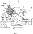
FIG. 3 is a partial cross-sectional view showing acombustor nozzle assembly 10. Referring toFIG. 3 , thefuel nozzle assembly 10 guides suctioned compressed air using ashroud 13 mounted on the outer side of anozzle body 11. - However, fluid separation may be generated on the
shroud 13 fuel-air mixture may stagnate due to a vortex area around a nozzle vane or swirler (not shown). Accordingly, flame may be generated around the nozzle vane. - Further, in the
shroud 13, a loss of pressure is generated by flow separation, which causes deterioration of the entire performance of the combustor. Therefore, there is a need to develop a fuel nozzle assembly that can solve the problems in the related art. - An object of the present invention is to provide a fuel nozzle assembly that can solve flame holding due to flow separation at an end of the shroud of existing fuel nozzles, can improve performance of a combustor, and can solve a loss of pressure in the entire combustor by preventing a loss of pressure due to flow separation by preventing the flow separation, and provide a gas turbine having the fuel nozzle assembly.
- The object is solved by the features of the independent claims. Preferred embodiments are given in the dependent claims.
- A fuel nozzle guide according to an aspect is disposed in a compressed air channel formed between a body and a housing of a gas turbine and includes a nozzle body disposed in the housing, a shroud mounted on an outer side of the nozzle body, and two or more flow guides arranged at predetermined distances from each other between the shroud and the outer surface of the nozzle body, and formed to correspond to the shape of an end of the shroud and the shape of the outer surface of the nozzle body.
- The flow guides may have a curved portion formed to correspond to the shape of an end of the shroud and a straight portion extending from the curved portion at a predetermined portion in a longitudinal direction of the nozzle body in parallel with the outer surface of the nozzle body.
- A first projection extending in the longitudinal direction of the nozzle body may be formed on a surface of the curved portion.
- The first projection may be inclined at a predetermined angle.
- A second projection extending in the longitudinal direction of the nozzle body may be formed on a surface of the straight portion.
- The first projection and the second projection may integrally extend.
- Two or more sub-channels spaced at a predetermined angle from each other may be formed through a joint between the curved portion and the straight portion of the flow guide.
- The sub-channel may be formed in parallel with the straight portion.
- An imaginary line connecting all of ends of the flow guides may be inclined at an acute angle toward a center of the nozzle body.
- The angle between the imaginary line and a center line of the nozzle body may be 35 to 55 degrees.
- The fuel nozzle assembly may further include two or more spacers arranged at predetermined angles on the outer surface of the nozzle body and connecting the flow guides and the nozzle body to each other.
- The spacers may extend a predetermined distance in the longitudinal direction of the nozzle body and may have an airfoil shape in a side cross-section.
- The spacers may extend at a predetermined angle from the center line of the nozzle body.
- A gas turbine according to another aspect has a fuel nozzle guide that is disposed in a compressed air channel formed between a body and a housing of a gas turbine, and the fuel nozzle assembly includes a nozzle body disposed in the housing, a shroud mounted on an outer side of the nozzle body, and two or more flow guides arranged at predetermined distances from each other between the shroud and the outer surface of the nozzle body and formed to correspond to the shape of an end of the shroud and the shape of the outer surface of the nozzle body.
- The flow guides may have a curved portion formed to correspond to the shape of an end of the shroud and a straight portion extending from the curved portion at a predetermined portion in a longitudinal direction of the nozzle body in parallel with the outer surface of the nozzle body.
- An imaginary line connecting all of ends of the flow guides may be inclined at an acute angle toward a center of the nozzle body.
- The fuel nozzle assembly may further include two or more spacers arranged at predetermined angles on the outer surface of the nozzle body and connecting the flow guides and the nozzle body to each other.
- As described above, according to the fuel nozzle assembly of the present disclosure, it is possible to provide a fuel nozzle assembly that can solve a loss of pressure due to flow separation by preventing flow separation and solve a loss of pressure of the entire combustor, and a gas turbine having the fuel nozzle assembly.
- Further, according to the fuel nozzle assembly of the present disclosure, since flow separation is prevented by the flow guides having a specific structure, it is possible to solve flame holding due to flow separation at an end of a shroud of existing fuel nozzles and improve the performance of a combustor.
- Further, according to the fuel nozzle assembly of the present disclosure, since the flow guides have a curved portion and a straight portion, it is possible to more stably guide fluid flowing along the flow guides, so it is possible to effectively prevent flow separation.
- Further, according to the fuel nozzle assembly of the present disclosure, since the first projections and the second projections are formed at specific positions, it is possible to more stably guide fluid flowing along the flow guides, so it is possible to effectively prevent flow separation.
- Further, according to the fuel nozzle assembly of the present disclosure, since sub-channels having a specific structure are formed at the joints between the curved portions and the straight portions, it is possible to prevent flow separation that may be generated at the joints between the curved portions and the straight portions and it is possible to more stably guide the fluid flowing along the flow guides. Accordingly, it is possible to more effectively prevent flow separation.
- Therefore, according to the fuel nozzle assembly of the present disclosure, since there are provided spacers having a specific structure, it is possible to more stably guide fluid flowing along the flow guides, so it is possible to effectively prevent flow separation.
- The above and other objects, features and other advantages of the present disclosure will be more clearly understood from the following detailed description when taken in conjunction with the accompanying drawings, in which:
-
FIG. 1 is a front view showing a gas turbine; -
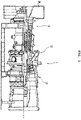
FIG. 2 is a partial cross-sectional view showing the combustor shown inFIG. 1 ; -
FIG. 3 is a partial cross-sectional view showing a fuel nozzle assembly; -
FIG. 4 is a partial cross-sectional perspective view showing a fuel nozzle assembly according to an exemplary embodiment; -
FIG. 5 is a partial cross-sectional view showing the fuel nozzle assembly according to an exemplary embodiment; -
FIG. 6 is a perspective view showing the fuel nozzle assembly according to an exemplary embodiment; -
FIG. 7 is a partial cross-sectional view showing in detail the structure of a flow guide of the fuel nozzle assembly shown inFIG. 5 ; -
FIG. 8 is a cross-sectional perspective view showing the flow guides of the fuel nozzle assembly according to an exemplary embodiment; -
FIG. 9 is a partial cross-sectional view showing a fuel nozzle assembly according to another exemplary embodiment; and -
FIGS. 10A and 10B are perspective views showing a spacer of the fuel nozzle assembly according to another exemplary embodiment. - Hereinafter, the exemplary embodiments are described in detail with reference to the drawings. The terms and words used in the present specification and claims should not be interpreted as being limited to typical meanings or dictionary definitions, but should be interpreted as having meanings and concepts relevant to the technical scope of the present invention.
- It should be understood that when an element is referred to as being "on" another element, the elements may be in contact with each other or there may be an intervening element present. Through the present specification, unless explicitly described otherwise, "comprising" any components will be understood to imply the inclusion of other components rather than the exclusion of any other components.
-
FIG. 4 is a partial cross-sectional perspective view showing a fuel nozzle assembly according to an exemplary embodiment. Referring toFIG. 4 , afuel nozzle assembly 100 according to the exemplary embodiment, which is disposed in a compressed air channel formed between the body of a combustor and a housing of a gas turbine, includesflow guides 130 having a specific structure. Thefuel nozzle assembly 100 according to the exemplary embodiment includesflow guides 130 having a specific structure to provide afuel nozzle assembly 100 that can solve a loss of pressure in the entire combustor by preventing a loss of pressure due to flow separation by preventing a flow separation, and provide a gas turbine having the fuel nozzle assembly. - The components of the
fuel nozzle assembly 100 according to the exemplary embodiment are described hereafter in detail with reference to the drawings. -
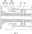
FIG. 5 is a partial cross-sectional view showing the fuel nozzle assembly according to an exemplary embodiment.FIG. 6 is a perspective view showing the fuel nozzle assembly according to an exemplary embodiment.FIG. 7 is a partial cross-sectional view showing in detail the structure of a flow guide of the fuel nozzle assembly shown inFIG. 5 . - Referring to the figures, the
fuel nozzle assembly 100 according to the exemplary embodiment includes anozzle body 110, ashroud 120, and flow guides 130. - The
nozzle body 110 has a fuel supply channel for supplying fuel and is disposed in the housing. Theshroud 120 is mounted on the outer side of thenozzle body 110. - Two or more flow guides 130 according to the exemplary embodiment are arranged at regular intervals between the
shroud 120 and the outer surface of thenozzle body 110. The flow guides 130 are curved to correspond to the shape of an end portion of theshroud 120 and then formed straight to correspond the shape of the outer surface of thenozzle body 110, which is advantageous in terms of flow. The surfaces of the flow guides 130 may be composed of a curved surface and a straight surface that are smoothly connected. - As shown in
FIG. 5 , the flow guides 130 each may have acurved portion 131 and astraight portion 132 that have specific structures. Thecurved portion 131, as shown inFIGS. 4 and5 , is formed to correspond to the shape of an end portion of theshroud 120. Thestraight portion 132 extends from thecurved portion 131 at a predetermined length in parallel with thenozzle body 110 and may be in parallel with the outer surface of thenozzle body 110. Two or more flow guides 130 according to the exemplary embodiment may be formed around the outer surface of thenozzle body 110. - As shown in
FIG. 7 , an imaginary line L connecting ends of the flow guides 130 may be inclined at an acute angle toward the center of thenozzle body 110. The angle 'a' between the imaginary line L and the center line C of thenozzle body 110 may be 35 to 55 degrees but may be a different angle as long as compressed air can be smoothly suctioned. - As the angle between the imaginary line connecting all the ends of the flow guides 130 and the center line of the
nozzle body 110 is an acute angle, thecurved portions 131 of the flow guides 130 closer to thenozzle body 110 further protrude with respect to the flow of compressed air. As can be seen fromFIG. 7 , in order to smoothly change the direction of the flow of compressed air that is turned almost 180°, the compressed air far from thenozzle body 110 should be guided to the inner flow guides 130 through theshroud 120. For more effective flow of compressed air, the flow guides 130 closer to thenozzle body 110 should guide the outside flow, so it is advantageous that thecurved portions 131 of theinner flow guide 130 further protrude to the flow of the compressed air. -
FIG. 8 is a cross-sectional perspective view showing the flow guides of the fuel nozzle assembly according to an exemplary embodiment. Referring toFIG. 8 , afirst projection 133 extending in the longitudinal direction of thenozzle body 110 is formed on a surface of thecurved portions 131 of the flow guides 130 according to the exemplary embodiment. Thefirst projection 133 can stably guide the flow flowing on thecurved portion 131, so it can effectively prevent flow separation. - If necessary, the
first protrusion 133, as shown inFIG. 8 , may be inclined at a predetermined angle from the center line of thenozzle body 110. Accordingly, it is possible to stably guide fluid into a desired direction. - Further, as shown in
FIG. 8 , asecond projection 134 extending in the longitudinal direction of thenozzle body 110 is formed on a surface of thestraight portions 132, so it can more stably guide fluid. In this case, thefirst projection 133 and thesecond projection 134 may integrally extend. If thefirst projection 133 and thesecond projection 134 are separately formed, flow separation of fluid may be generated at the spaced ends, so it is not advantageous. -
FIG. 9 is a partial cross-sectional view showing a fuel nozzle assembly according to another exemplary embodiment. Referring toFIG. 9 , two ormore sub-channels 135 are formed through the joints of thecurved portions 131 and thestraight portions 132 of the flow guides 130 according to the exemplary embodiment. The sub-channels 135 may be formed in parallel with thestraight portions 132. - Since the sub-channels 135 having a specific structure are formed at the joints between the
curved portions 131 and thestraight portions 132, it is possible to prevent flow separation that may be generated at the joints between thecurved portions 131 and thestraight portions 132 and it is possible to more stably guide the fluid flowing along the flow guides. Accordingly, it is possible to more effectively prevent flow separation. -
FIGS. 10A and 10B are perspective views showing a spacer of the fuel nozzle assembly according to another exemplary embodiment. Referring toFIGS. 10A and 10B withFIG. 6 , the fuel nozzle assembly according to the exemplary embodiment may further includespacers 140 connecting the flow guides 130 and thenozzle body 110. - Two or
more spacers 140 according to the exemplary embodiment may be formed around the outer surface of thenozzle body 110 at predetermined angles. Thespacers 140 extend a predetermined length in the longitudinal direction of thenozzle body 110 and may have an airfoil shape in a side cross-section. - As shown in
FIG. 10A , thespacers 140 according to the exemplary embodiment may extend in parallel with the center line C of thenozzle body 110. In order to guide flow in a specific direction, thespacers 140 may be mounted at a predetermined angle 'b' from the center line C of thenozzle body 110 as shown inFIG. 10B . - Therefore, according to the exemplary embodiment, the
spacers 140 having a specific structure more stably guide fluid flowing along the flow guides 130, so it is possible to effectively prevent flow separation. - Further, the exemplary embodiments can provide a gas turbine having the
fuel nozzle assembly 100 according to the present disclosure, so it is possible to provide a gas turbine of which the performance of the combustor can be remarkably improved and the efficiency is improved. - Specific exemplary embodiments were described above. However, it should understood that the present disclosure is not limited to the specific exemplary embodiments and all modifications, equivalents, and substitutions should be construed as being included in the scope of the present disclosure as defined in claims.
- That is, the present disclosure is not limited to the specific exemplary embodiments described above, but may be changed in various ways without departing from the concept of the present disclosure as defined in claims, and the modifications are included in the protective range of the present disclosure.
Claims (15)
- A fuel nozzle assembly (100) for a gas turbine (1), comprising:a nozzle body (110) configured to be disposed in a compressed air channel formed between a body and a housing of the gas turbine;a shroud (120) mounted on an outer surface of the nozzle body (110); andtwo or more flow guides (130) arranged at predetermined distances from each other between the shroud (120) and the outer surface of the nozzle body (110) and having a shape that corresponds to the shape of an end portion of the shroud (120) and the outer surface of the nozzle body (110).
- The fuel nozzle assembly (100) of claim 1, wherein the flow guides (130) include:a curved portion (131) formed to correspond to the shape of the end portion of the shroud (120); anda straight portion (132) extending from the curved portion (131) at a predetermined distance in a longitudinal direction parallel with the outer surface of the nozzle body (110).
- The fuel nozzle assembly (100) of claim 2, wherein a first projection (133) extending in the longitudinal direction of the nozzle body (110) is formed on a surface of the curved portion (131).
- The fuel nozzle assembly (100) of claim 3, wherein the first projection (133) is inclined at a predetermined angle.
- The fuel nozzle assembly (100) of claim 2, 3 or 4, wherein a second projection (134) extending in the longitudinal direction of the nozzle body (110) is formed on the surface of the straight portion (132).
- The fuel nozzle assembly (100) of claim 5, wherein the first projection (133) and the second projection (134) integrally extend.
- The fuel nozzle assembly (100) of any one of the preceding claims, wherein a sub-channel (135) is formed through a joint between the curved portion (131) and the straight portion (132) of the flow guide (130).
- The fuel nozzle assembly (100) of claim 7, wherein the sub-channel (135) is parallel with the straight portion (132).
- The fuel nozzle assembly (100) of any one of the preceding claims, wherein the flow guides (130) are arranged such that ends of the flow guides (130) form an imaginary line (L) that is inclined at an acute angle (a) from a center of the nozzle body (110).
- The fuel nozzle assembly (100) of claim 9, wherein the angle (a) formed between the imaginary line (L) and the center of the nozzle body (110) is between about 35 to 55 degrees.
- The fuel nozzle assembly (100) of any one of the preceding claims, further comprising two or more spacers (140) arranged at predetermined angles on the outer surface of the nozzle body (110) and connecting the flow guides (130) and the nozzle body (110) to each other.
- The fuel nozzle assembly (100) of claim 11, wherein the spacers (140) extend a predetermined distance in the longitudinal direction of the nozzle body (110) and have an airfoil shape in a side cross-section.
- The fuel nozzle assembly (100) of claim 11 or 12, wherein the spacers (140) extend at a predetermined angle (b) from the center of the nozzle body (110).
- A gas turbine (1), comprising:a compressed air channel formed between a body and a housing of a combustor (12); anda fuel nozzle assembly (100) as claimed in any one of the preceding claims and being disposed in the compressed air channel.
- The gas turbine (1) of claim 14, wherein the flow guides (130) are arranged such that ends of the flow guides (130) form an imaginary line (L) that is inclined at an acute angle (a) from a center of the nozzle body (110).
Applications Claiming Priority (1)
| Application Number | Priority Date | Filing Date | Title |
|---|---|---|---|
| KR1020170049624A KR101872801B1 (en) | 2017-04-18 | 2017-04-18 | Combustor Fuel Nozzle Assembly And Gas Turbine Having The Same |
Publications (2)
| Publication Number | Publication Date |
|---|---|
| EP3392569A1 true EP3392569A1 (en) | 2018-10-24 |
| EP3392569B1 EP3392569B1 (en) | 2021-03-17 |
Family
ID=59969038
Family Applications (1)
| Application Number | Title | Priority Date | Filing Date |
|---|---|---|---|
| EP17193079.5A Active EP3392569B1 (en) | 2017-04-18 | 2017-09-26 | Fuel nozzle assembly with a flow guide assembly and a gas turbine |
Country Status (4)
| Country | Link |
|---|---|
| US (1) | US11221142B2 (en) |
| EP (1) | EP3392569B1 (en) |
| JP (1) | JP6458841B2 (en) |
| KR (1) | KR101872801B1 (en) |
Families Citing this family (4)
| Publication number | Priority date | Publication date | Assignee | Title |
|---|---|---|---|---|
| KR102340397B1 (en) | 2020-05-07 | 2021-12-15 | 두산중공업 주식회사 | Combustor, and gas turbine including the same |
| KR102382634B1 (en) * | 2020-12-22 | 2022-04-01 | 두산중공업 주식회사 | Nozzle for combustor, combustor, and gas turbine including the same |
| US11761632B2 (en) * | 2021-08-05 | 2023-09-19 | General Electric Company | Combustor swirler with vanes incorporating open area |
| KR102858816B1 (en) * | 2023-12-15 | 2025-09-10 | 두산에너빌리티 주식회사 | Combustor, gas turbine including the same, flow guide member manufacturing method |
Citations (9)
| Publication number | Priority date | Publication date | Assignee | Title |
|---|---|---|---|---|
| US5540406A (en) * | 1993-10-25 | 1996-07-30 | Occhipinti; Anthony C. | Hydrofoils and airfoils |
| US20090173074A1 (en) * | 2008-01-03 | 2009-07-09 | General Electric Company | Integrated fuel nozzle ifc |
| US20090183511A1 (en) * | 2008-01-18 | 2009-07-23 | General Electric Company | Swozzle design for gas turbine combustor |
| US20110094232A1 (en) * | 2009-10-28 | 2011-04-28 | General Electric Company | Apparatus for conditioning airflow through a nozzle |
| US20120024985A1 (en) * | 2010-08-02 | 2012-02-02 | General Electric Company | Integrated fuel nozzle and inlet flow conditioner and related method |
| JP2012145312A (en) * | 2011-01-14 | 2012-08-02 | Mitsubishi Heavy Ind Ltd | Combustor and gas turbine |
| EP2568221A2 (en) * | 2011-09-09 | 2013-03-13 | General Electric Company | Turning guide for combustion fuel nozzle in gas turbine and method to turn fuel flow entering combustion chamber |
| US20150113993A1 (en) * | 2013-10-30 | 2015-04-30 | Honeywell International Inc. | Gas turbine engines having fuel injector shrouds with interior ribs |
| WO2016209101A1 (en) * | 2015-06-24 | 2016-12-29 | General Electric Company | Fuel nozzle assembly having a premix flame stabilizer |
Family Cites Families (13)
| Publication number | Priority date | Publication date | Assignee | Title |
|---|---|---|---|---|
| US2558816A (en) * | 1947-08-16 | 1951-07-03 | United Aircraft Corp | Fluid mixing device |
| US4175640A (en) * | 1975-03-31 | 1979-11-27 | Boeing Commercial Airplane Company | Vortex generators for internal mixing in a turbofan engine |
| JPH04126921A (en) * | 1990-09-19 | 1992-04-27 | Hitachi Ltd | Premix-type gas turbine combustor |
| DE112005001695A5 (en) * | 2004-08-27 | 2007-11-22 | Alstom Technology Ltd. | mixer assembly |
| KR20090127353A (en) | 2007-04-05 | 2009-12-10 | 보르그워너 인코퍼레이티드 | Ring Fan and Shroud Air Guide System |
| WO2011018853A1 (en) * | 2009-08-13 | 2011-02-17 | 三菱重工業株式会社 | Combustor |
| US20130025285A1 (en) * | 2011-07-29 | 2013-01-31 | General Electric Company | System for conditioning air flow into a multi-nozzle assembly |
| JP6037812B2 (en) | 2012-12-13 | 2016-12-07 | 三菱日立パワーシステムズ株式会社 | Fuel nozzle, combustion burner, gas turbine combustor and gas turbine |
| JP6318443B2 (en) * | 2013-01-22 | 2018-05-09 | 三菱日立パワーシステムズ株式会社 | Combustor and rotating machine |
| CN104566459B (en) * | 2014-12-08 | 2017-12-12 | 北京华清燃气轮机与煤气化联合循环工程技术有限公司 | A kind of gas-turbine combustion chamber is classified nozzle of air supply |
| KR102066943B1 (en) | 2014-12-09 | 2020-01-16 | 한화에어로스페이스 주식회사 | Fuel nozzle for combustor |
| US20160281978A1 (en) * | 2015-03-26 | 2016-09-29 | Luiz Claudio FERNANDES | Fuel Nozzle With Multiple Flow Divider Air Inlet |
| RU2015156419A (en) * | 2015-12-28 | 2017-07-04 | Дженерал Электрик Компани | The fuel injector assembly made with a flame stabilizer pre-mixed mixture |
-
2017
- 2017-04-18 KR KR1020170049624A patent/KR101872801B1/en active Active
- 2017-09-25 US US15/714,771 patent/US11221142B2/en active Active
- 2017-09-26 JP JP2017184714A patent/JP6458841B2/en active Active
- 2017-09-26 EP EP17193079.5A patent/EP3392569B1/en active Active
Patent Citations (9)
| Publication number | Priority date | Publication date | Assignee | Title |
|---|---|---|---|---|
| US5540406A (en) * | 1993-10-25 | 1996-07-30 | Occhipinti; Anthony C. | Hydrofoils and airfoils |
| US20090173074A1 (en) * | 2008-01-03 | 2009-07-09 | General Electric Company | Integrated fuel nozzle ifc |
| US20090183511A1 (en) * | 2008-01-18 | 2009-07-23 | General Electric Company | Swozzle design for gas turbine combustor |
| US20110094232A1 (en) * | 2009-10-28 | 2011-04-28 | General Electric Company | Apparatus for conditioning airflow through a nozzle |
| US20120024985A1 (en) * | 2010-08-02 | 2012-02-02 | General Electric Company | Integrated fuel nozzle and inlet flow conditioner and related method |
| JP2012145312A (en) * | 2011-01-14 | 2012-08-02 | Mitsubishi Heavy Ind Ltd | Combustor and gas turbine |
| EP2568221A2 (en) * | 2011-09-09 | 2013-03-13 | General Electric Company | Turning guide for combustion fuel nozzle in gas turbine and method to turn fuel flow entering combustion chamber |
| US20150113993A1 (en) * | 2013-10-30 | 2015-04-30 | Honeywell International Inc. | Gas turbine engines having fuel injector shrouds with interior ribs |
| WO2016209101A1 (en) * | 2015-06-24 | 2016-12-29 | General Electric Company | Fuel nozzle assembly having a premix flame stabilizer |
Also Published As
| Publication number | Publication date |
|---|---|
| JP2018179484A (en) | 2018-11-15 |
| KR101872801B1 (en) | 2018-06-29 |
| US11221142B2 (en) | 2022-01-11 |
| US20180299128A1 (en) | 2018-10-18 |
| JP6458841B2 (en) | 2019-01-30 |
| EP3392569B1 (en) | 2021-03-17 |
Similar Documents
| Publication | Publication Date | Title |
|---|---|---|
| US11221142B2 (en) | Fuel nozzle assembly and gas turbine having the same | |
| US8973369B2 (en) | Gas-turbine burner having inflow guide means | |
| US20130175015A1 (en) | Double-jet type film cooling structure | |
| EP2722592B1 (en) | Multiple cone gas turbine burner | |
| JP2016041929A (en) | Fuel injector assembly in combustion turbine engine | |
| US10240791B2 (en) | Combustion burner, combustor, and gas turbine having a swirl vane with opposite directed surfaces | |
| US20170370232A1 (en) | Turbine airfoil cooling system with chordwise extending squealer tip cooling channel | |
| CN106918054A (en) | Fuel nozzle assembly with premixed flame stabilizer | |
| CN108350809B (en) | Combustion canisters, gas turbine combustors, and gas turbines | |
| KR102153066B1 (en) | Turbine blade having cooling hole at winglet and gas turbine comprising the same | |
| US11125090B2 (en) | First-stage stationary vane of gas turbine and gas turbine | |
| KR102178956B1 (en) | Turbine vane and ring segment and gas turbine comprising the same | |
| US9551229B2 (en) | Turbine airfoil with an internal cooling system having trip strips with reduced pressure drop | |
| CN107101224A (en) | A kind of can burner and gas turbine | |
| US11299994B2 (en) | First-stage stator vane for gas turbine, gas turbine, stator vane unit for gas turbine, and combustor assembly | |
| CN103363546B (en) | Transition nozzle combustion system | |
| EP3392570B1 (en) | Combustor nozzle assembly and gas turbine having the same | |
| CN105091031A (en) | Turbomachine combustor including combustor sleeve baffle | |
| US11795876B2 (en) | Outlet seal, outlet seal set, and gas turbine | |
| KR102062527B1 (en) | Burner Having Fuel Injection Peg, And Gas Turbine Having The Same | |
| US11280203B2 (en) | Gas turbine including first-stage stator vanes | |
| US11085642B2 (en) | Combustor with radially varying leading end portion of basket and gas turbine | |
| WO2015134006A1 (en) | Turbine blade with film cooling leading edge showerhead |
Legal Events
| Date | Code | Title | Description |
|---|---|---|---|
| PUAI | Public reference made under article 153(3) epc to a published international application that has entered the european phase |
Free format text: ORIGINAL CODE: 0009012 |
|
| STAA | Information on the status of an ep patent application or granted ep patent |
Free format text: STATUS: REQUEST FOR EXAMINATION WAS MADE |
|
| 17P | Request for examination filed |
Effective date: 20170926 |
|
| AK | Designated contracting states |
Kind code of ref document: A1 Designated state(s): AL AT BE BG CH CY CZ DE DK EE ES FI FR GB GR HR HU IE IS IT LI LT LU LV MC MK MT NL NO PL PT RO RS SE SI SK SM TR |
|
| AX | Request for extension of the european patent |
Extension state: BA ME |
|
| RBV | Designated contracting states (corrected) |
Designated state(s): AL AT BE BG CH CY CZ DE DK EE ES FI FR GB GR HR HU IE IS IT LI LT LU LV MC MK MT NL NO PL PT RO RS SE SI SK SM TR |
|
| RAP1 | Party data changed (applicant data changed or rights of an application transferred) |
Owner name: DOOSAN HEAVY INDUSTRIES & CONSTRUCTION CO., LTD. |
|
| STAA | Information on the status of an ep patent application or granted ep patent |
Free format text: STATUS: EXAMINATION IS IN PROGRESS |
|
| 17Q | First examination report despatched |
Effective date: 20191219 |
|
| GRAP | Despatch of communication of intention to grant a patent |
Free format text: ORIGINAL CODE: EPIDOSNIGR1 |
|
| STAA | Information on the status of an ep patent application or granted ep patent |
Free format text: STATUS: GRANT OF PATENT IS INTENDED |
|
| INTG | Intention to grant announced |
Effective date: 20201020 |
|
| GRAS | Grant fee paid |
Free format text: ORIGINAL CODE: EPIDOSNIGR3 |
|
| GRAA | (expected) grant |
Free format text: ORIGINAL CODE: 0009210 |
|
| STAA | Information on the status of an ep patent application or granted ep patent |
Free format text: STATUS: THE PATENT HAS BEEN GRANTED |
|
| AK | Designated contracting states |
Kind code of ref document: B1 Designated state(s): AL AT BE BG CH CY CZ DE DK EE ES FI FR GB GR HR HU IE IS IT LI LT LU LV MC MK MT NL NO PL PT RO RS SE SI SK SM TR |
|
| REG | Reference to a national code |
Ref country code: GB Ref legal event code: FG4D |
|
| REG | Reference to a national code |
Ref country code: CH Ref legal event code: EP |
|
| REG | Reference to a national code |
Ref country code: DE Ref legal event code: R096 Ref document number: 602017034660 Country of ref document: DE |
|
| REG | Reference to a national code |
Ref country code: IE Ref legal event code: FG4D |
|
| REG | Reference to a national code |
Ref country code: AT Ref legal event code: REF Ref document number: 1372589 Country of ref document: AT Kind code of ref document: T Effective date: 20210415 |
|
| REG | Reference to a national code |
Ref country code: LT Ref legal event code: MG9D |
|
| PG25 | Lapsed in a contracting state [announced via postgrant information from national office to epo] |
Ref country code: NO Free format text: LAPSE BECAUSE OF FAILURE TO SUBMIT A TRANSLATION OF THE DESCRIPTION OR TO PAY THE FEE WITHIN THE PRESCRIBED TIME-LIMIT Effective date: 20210617 Ref country code: FI Free format text: LAPSE BECAUSE OF FAILURE TO SUBMIT A TRANSLATION OF THE DESCRIPTION OR TO PAY THE FEE WITHIN THE PRESCRIBED TIME-LIMIT Effective date: 20210317 Ref country code: GR Free format text: LAPSE BECAUSE OF FAILURE TO SUBMIT A TRANSLATION OF THE DESCRIPTION OR TO PAY THE FEE WITHIN THE PRESCRIBED TIME-LIMIT Effective date: 20210618 Ref country code: HR Free format text: LAPSE BECAUSE OF FAILURE TO SUBMIT A TRANSLATION OF THE DESCRIPTION OR TO PAY THE FEE WITHIN THE PRESCRIBED TIME-LIMIT Effective date: 20210317 Ref country code: BG Free format text: LAPSE BECAUSE OF FAILURE TO SUBMIT A TRANSLATION OF THE DESCRIPTION OR TO PAY THE FEE WITHIN THE PRESCRIBED TIME-LIMIT Effective date: 20210617 |
|
| REG | Reference to a national code |
Ref country code: AT Ref legal event code: MK05 Ref document number: 1372589 Country of ref document: AT Kind code of ref document: T Effective date: 20210317 |
|
| REG | Reference to a national code |
Ref country code: NL Ref legal event code: MP Effective date: 20210317 |
|
| PG25 | Lapsed in a contracting state [announced via postgrant information from national office to epo] |
Ref country code: SE Free format text: LAPSE BECAUSE OF FAILURE TO SUBMIT A TRANSLATION OF THE DESCRIPTION OR TO PAY THE FEE WITHIN THE PRESCRIBED TIME-LIMIT Effective date: 20210317 Ref country code: RS Free format text: LAPSE BECAUSE OF FAILURE TO SUBMIT A TRANSLATION OF THE DESCRIPTION OR TO PAY THE FEE WITHIN THE PRESCRIBED TIME-LIMIT Effective date: 20210317 Ref country code: LV Free format text: LAPSE BECAUSE OF FAILURE TO SUBMIT A TRANSLATION OF THE DESCRIPTION OR TO PAY THE FEE WITHIN THE PRESCRIBED TIME-LIMIT Effective date: 20210317 |
|
| PG25 | Lapsed in a contracting state [announced via postgrant information from national office to epo] |
Ref country code: NL Free format text: LAPSE BECAUSE OF FAILURE TO SUBMIT A TRANSLATION OF THE DESCRIPTION OR TO PAY THE FEE WITHIN THE PRESCRIBED TIME-LIMIT Effective date: 20210317 |
|
| PG25 | Lapsed in a contracting state [announced via postgrant information from national office to epo] |
Ref country code: EE Free format text: LAPSE BECAUSE OF FAILURE TO SUBMIT A TRANSLATION OF THE DESCRIPTION OR TO PAY THE FEE WITHIN THE PRESCRIBED TIME-LIMIT Effective date: 20210317 Ref country code: CZ Free format text: LAPSE BECAUSE OF FAILURE TO SUBMIT A TRANSLATION OF THE DESCRIPTION OR TO PAY THE FEE WITHIN THE PRESCRIBED TIME-LIMIT Effective date: 20210317 Ref country code: LT Free format text: LAPSE BECAUSE OF FAILURE TO SUBMIT A TRANSLATION OF THE DESCRIPTION OR TO PAY THE FEE WITHIN THE PRESCRIBED TIME-LIMIT Effective date: 20210317 Ref country code: AT Free format text: LAPSE BECAUSE OF FAILURE TO SUBMIT A TRANSLATION OF THE DESCRIPTION OR TO PAY THE FEE WITHIN THE PRESCRIBED TIME-LIMIT Effective date: 20210317 Ref country code: SM Free format text: LAPSE BECAUSE OF FAILURE TO SUBMIT A TRANSLATION OF THE DESCRIPTION OR TO PAY THE FEE WITHIN THE PRESCRIBED TIME-LIMIT Effective date: 20210317 |
|
| PG25 | Lapsed in a contracting state [announced via postgrant information from national office to epo] |
Ref country code: PL Free format text: LAPSE BECAUSE OF FAILURE TO SUBMIT A TRANSLATION OF THE DESCRIPTION OR TO PAY THE FEE WITHIN THE PRESCRIBED TIME-LIMIT Effective date: 20210317 Ref country code: PT Free format text: LAPSE BECAUSE OF FAILURE TO SUBMIT A TRANSLATION OF THE DESCRIPTION OR TO PAY THE FEE WITHIN THE PRESCRIBED TIME-LIMIT Effective date: 20210719 Ref country code: RO Free format text: LAPSE BECAUSE OF FAILURE TO SUBMIT A TRANSLATION OF THE DESCRIPTION OR TO PAY THE FEE WITHIN THE PRESCRIBED TIME-LIMIT Effective date: 20210317 Ref country code: SK Free format text: LAPSE BECAUSE OF FAILURE TO SUBMIT A TRANSLATION OF THE DESCRIPTION OR TO PAY THE FEE WITHIN THE PRESCRIBED TIME-LIMIT Effective date: 20210317 Ref country code: IS Free format text: LAPSE BECAUSE OF FAILURE TO SUBMIT A TRANSLATION OF THE DESCRIPTION OR TO PAY THE FEE WITHIN THE PRESCRIBED TIME-LIMIT Effective date: 20210717 |
|
| REG | Reference to a national code |
Ref country code: DE Ref legal event code: R097 Ref document number: 602017034660 Country of ref document: DE |
|
| PLBE | No opposition filed within time limit |
Free format text: ORIGINAL CODE: 0009261 |
|
| STAA | Information on the status of an ep patent application or granted ep patent |
Free format text: STATUS: NO OPPOSITION FILED WITHIN TIME LIMIT |
|
| PG25 | Lapsed in a contracting state [announced via postgrant information from national office to epo] |
Ref country code: DK Free format text: LAPSE BECAUSE OF FAILURE TO SUBMIT A TRANSLATION OF THE DESCRIPTION OR TO PAY THE FEE WITHIN THE PRESCRIBED TIME-LIMIT Effective date: 20210317 Ref country code: AL Free format text: LAPSE BECAUSE OF FAILURE TO SUBMIT A TRANSLATION OF THE DESCRIPTION OR TO PAY THE FEE WITHIN THE PRESCRIBED TIME-LIMIT Effective date: 20210317 Ref country code: ES Free format text: LAPSE BECAUSE OF FAILURE TO SUBMIT A TRANSLATION OF THE DESCRIPTION OR TO PAY THE FEE WITHIN THE PRESCRIBED TIME-LIMIT Effective date: 20210317 |
|
| 26N | No opposition filed |
Effective date: 20211220 |
|
| PG25 | Lapsed in a contracting state [announced via postgrant information from national office to epo] |
Ref country code: SI Free format text: LAPSE BECAUSE OF FAILURE TO SUBMIT A TRANSLATION OF THE DESCRIPTION OR TO PAY THE FEE WITHIN THE PRESCRIBED TIME-LIMIT Effective date: 20210317 |
|
| PG25 | Lapsed in a contracting state [announced via postgrant information from national office to epo] |
Ref country code: IT Free format text: LAPSE BECAUSE OF FAILURE TO SUBMIT A TRANSLATION OF THE DESCRIPTION OR TO PAY THE FEE WITHIN THE PRESCRIBED TIME-LIMIT Effective date: 20210317 |
|
| REG | Reference to a national code |
Ref country code: CH Ref legal event code: PL |
|
| REG | Reference to a national code |
Ref country code: BE Ref legal event code: MM Effective date: 20210930 |
|
| GBPC | Gb: european patent ceased through non-payment of renewal fee |
Effective date: 20210926 |
|
| PG25 | Lapsed in a contracting state [announced via postgrant information from national office to epo] |
Ref country code: IS Free format text: LAPSE BECAUSE OF FAILURE TO SUBMIT A TRANSLATION OF THE DESCRIPTION OR TO PAY THE FEE WITHIN THE PRESCRIBED TIME-LIMIT Effective date: 20210717 Ref country code: MC Free format text: LAPSE BECAUSE OF FAILURE TO SUBMIT A TRANSLATION OF THE DESCRIPTION OR TO PAY THE FEE WITHIN THE PRESCRIBED TIME-LIMIT Effective date: 20210317 |
|
| PG25 | Lapsed in a contracting state [announced via postgrant information from national office to epo] |
Ref country code: LU Free format text: LAPSE BECAUSE OF NON-PAYMENT OF DUE FEES Effective date: 20210926 Ref country code: IE Free format text: LAPSE BECAUSE OF NON-PAYMENT OF DUE FEES Effective date: 20210926 Ref country code: GB Free format text: LAPSE BECAUSE OF NON-PAYMENT OF DUE FEES Effective date: 20210926 Ref country code: FR Free format text: LAPSE BECAUSE OF NON-PAYMENT OF DUE FEES Effective date: 20210930 Ref country code: BE Free format text: LAPSE BECAUSE OF NON-PAYMENT OF DUE FEES Effective date: 20210930 |
|
| PG25 | Lapsed in a contracting state [announced via postgrant information from national office to epo] |
Ref country code: LI Free format text: LAPSE BECAUSE OF NON-PAYMENT OF DUE FEES Effective date: 20210930 Ref country code: CH Free format text: LAPSE BECAUSE OF NON-PAYMENT OF DUE FEES Effective date: 20210930 |
|
| PG25 | Lapsed in a contracting state [announced via postgrant information from national office to epo] |
Ref country code: CY Free format text: LAPSE BECAUSE OF FAILURE TO SUBMIT A TRANSLATION OF THE DESCRIPTION OR TO PAY THE FEE WITHIN THE PRESCRIBED TIME-LIMIT Effective date: 20210317 |
|
| PG25 | Lapsed in a contracting state [announced via postgrant information from national office to epo] |
Ref country code: HU Free format text: LAPSE BECAUSE OF FAILURE TO SUBMIT A TRANSLATION OF THE DESCRIPTION OR TO PAY THE FEE WITHIN THE PRESCRIBED TIME-LIMIT; INVALID AB INITIO Effective date: 20170926 |
|
| PG25 | Lapsed in a contracting state [announced via postgrant information from national office to epo] |
Ref country code: MK Free format text: LAPSE BECAUSE OF FAILURE TO SUBMIT A TRANSLATION OF THE DESCRIPTION OR TO PAY THE FEE WITHIN THE PRESCRIBED TIME-LIMIT Effective date: 20210317 |
|
| PG25 | Lapsed in a contracting state [announced via postgrant information from national office to epo] |
Ref country code: TR Free format text: LAPSE BECAUSE OF FAILURE TO SUBMIT A TRANSLATION OF THE DESCRIPTION OR TO PAY THE FEE WITHIN THE PRESCRIBED TIME-LIMIT Effective date: 20210317 |
|
| PG25 | Lapsed in a contracting state [announced via postgrant information from national office to epo] |
Ref country code: MT Free format text: LAPSE BECAUSE OF FAILURE TO SUBMIT A TRANSLATION OF THE DESCRIPTION OR TO PAY THE FEE WITHIN THE PRESCRIBED TIME-LIMIT Effective date: 20210317 |
|
| PGFP | Annual fee paid to national office [announced via postgrant information from national office to epo] |
Ref country code: DE Payment date: 20250702 Year of fee payment: 9 |