EP3392495A1 - Reusable high pressure and high temperature energetic ignition system - Google Patents
Reusable high pressure and high temperature energetic ignition system Download PDFInfo
- Publication number
- EP3392495A1 EP3392495A1 EP18155450.2A EP18155450A EP3392495A1 EP 3392495 A1 EP3392495 A1 EP 3392495A1 EP 18155450 A EP18155450 A EP 18155450A EP 3392495 A1 EP3392495 A1 EP 3392495A1
- Authority
- EP
- European Patent Office
- Prior art keywords
- energetic
- arrangement
- ignition
- pressure vessel
- seal
- Prior art date
- Legal status (The legal status is an assumption and is not a legal conclusion. Google has not performed a legal analysis and makes no representation as to the accuracy of the status listed.)
- Granted
Links
Images



Classifications
-
- F—MECHANICAL ENGINEERING; LIGHTING; HEATING; WEAPONS; BLASTING
- F02—COMBUSTION ENGINES; HOT-GAS OR COMBUSTION-PRODUCT ENGINE PLANTS
- F02K—JET-PROPULSION PLANTS
- F02K9/00—Rocket-engine plants, i.e. plants carrying both fuel and oxidant therefor; Control thereof
- F02K9/94—Re-ignitable or restartable rocket- engine plants; Intermittently operated rocket-engine plants
-
- F—MECHANICAL ENGINEERING; LIGHTING; HEATING; WEAPONS; BLASTING
- F02—COMBUSTION ENGINES; HOT-GAS OR COMBUSTION-PRODUCT ENGINE PLANTS
- F02K—JET-PROPULSION PLANTS
- F02K9/00—Rocket-engine plants, i.e. plants carrying both fuel and oxidant therefor; Control thereof
- F02K9/95—Rocket-engine plants, i.e. plants carrying both fuel and oxidant therefor; Control thereof characterised by starting or ignition means or arrangements
-
- F—MECHANICAL ENGINEERING; LIGHTING; HEATING; WEAPONS; BLASTING
- F02—COMBUSTION ENGINES; HOT-GAS OR COMBUSTION-PRODUCT ENGINE PLANTS
- F02K—JET-PROPULSION PLANTS
- F02K9/00—Rocket-engine plants, i.e. plants carrying both fuel and oxidant therefor; Control thereof
- F02K9/96—Rocket-engine plants, i.e. plants carrying both fuel and oxidant therefor; Control thereof characterised by specially adapted arrangements for testing or measuring
-
- F—MECHANICAL ENGINEERING; LIGHTING; HEATING; WEAPONS; BLASTING
- F05—INDEXING SCHEMES RELATING TO ENGINES OR PUMPS IN VARIOUS SUBCLASSES OF CLASSES F01-F04
- F05D—INDEXING SCHEME FOR ASPECTS RELATING TO NON-POSITIVE-DISPLACEMENT MACHINES OR ENGINES, GAS-TURBINES OR JET-PROPULSION PLANTS
- F05D2260/00—Function
- F05D2260/83—Testing, e.g. methods, components or tools therefor
Definitions
- the present disclosure relates generally to energetic systems, and more particularly, to a reusable system for energetics.
- Energetic systems may be used for various applications which use explosive energy to achieve a desired result. Testing and operating of energetic assemblies (rocket motors, test vessels, thrusters, actuators, etc.) use various samples of production hardware built, due to the inability to re-use ignition source and energetic materials. Ignition systems for pressure vessels may be entirely replaced after use due to the nature of the ignition system and ignition of the energetic therein.
- An energetic ignition arrangement may comprise a pressure vessel arrangement, comprising a pressure vessel, and an ignition system arrangement.
- the ignition system arrangement may comprise an ignitor housing coupled to the pressure vessel and defining a sealing aperture, a seal disposed in the sealing aperture, and an electric match extending through the ignitor housing, wherein at least the ignitor housing and the pressure vessel are reusable after the energetic ignition arrangement has been employed in an ignition event.
- the electric match may extend through the seal.
- the electric match may comprise a heating element, an energetic compound coupled to the heating element, and at least one wire lead coupled to the heating element configured to supply electric power to the heating element.
- the seal may hermetically seal to the ignitor housing and to the at least one wire lead.
- the energetic ignition arrangement may further comprise a first ceramic isolator and a second ceramic isolator, wherein the first ceramic isolator and the second ceramic isolator electrically insulate the at least one wire lead, and wherein the seal is located between the first ceramic isolator and the second ceramic isolator.
- the pressure vessel may define a cavity within which the electric match is positionable. The electric match may be configured to ignite an energetic disposed in the cavity.
- the seal may comprise a polymeric material and the first ceramic isolator and the second ceramic isolator may comprise a ceramic material. At least one of the seal, the first ceramic isolator, and the second ceramic isolator may be reusable after the energetic ignition arrangement has been employed in the ignition event.
- the ignition system arrangement may further comprise a jam nut threadably coupled to the ignitor housing, and a follower disposed between the jam nut and the seal, wherein the seal is configured to be compressed between the follower and the ignitor housing in response to the jam nut being rotated relative to the ignitor housing.
- An energetic ignition arrangement may comprise a pressure vessel arrangement, comprising an ignitor pressure vessel defining an energetic cavity, a propellant pressure vessel defining a propellant cavity, wherein the ignitor pressure vessel is coupled to the propellant pressure vessel, an energetic disposed in the energetic cavity, and a propellant disposed in the propellant pressure vessel, and an ignition system arrangement.
- the ignition system arrangement may comprise an ignitor housing coupled to the ignitor pressure vessel and defining a sealing aperture, a seal disposed in the sealing aperture configured to hermetically seals the ignitor housing, and an electric match extending through the ignitor housing, wherein at least the ignitor housing and the ignitor pressure vessel are reusable after the energetic ignition arrangement has been employed in an ignition event.
- the electric match may extend through the seal.
- the electric match may comprise a heating element, an energetic compound coupled to the heating element, and at least one wire lead coupled to the heating element configured to supply electric power to the heating element.
- the energetic ignition arrangement may further comprise a first ceramic isolator and a second ceramic isolator, wherein the first ceramic isolator and the second ceramic isolator electrically insulate the at least one wire, and wherein the seal is located between the first ceramic isolator and the second ceramic isolator.
- the ignition event may comprise the electric match igniting the energetic and the energetic igniting the propellant in response to the electric match igniting the energetic.
- the seal may comprise a polymeric material and the first ceramic isolator and the second ceramic isolator may comprise a ceramic material. At least one of the seal, the first ceramic isolator, and the second ceramic isolator may be reusable after the energetic ignition arrangement has been employed in the ignition event.
- the ignition system arrangement may further comprise a jam nut coupled to the ignitor housing, and a follower disposed between the jam nut and the seal, wherein the seal is configured to be compressed between the follower and the ignitor housing in response to the jam nut being tightened.
- the energetic ignition arrangement may comprise a pressure vessel arrangement comprising a pressure vessel, and an ignition system arrangement comprising an ignitor housing coupled to the pressure vessel and defining a sealing aperture, a seal disposed in the sealing aperture, and an electric match extending through the ignitor housing
- the method may comprise initiating a first ignition event at a first time, comprising igniting the electric match, and igniting, by the electric match, an energetic, replacing the electric match with a second electric match, initiating a second ignition event at a second time, comprising igniting the second electric match, and igniting, by the second electric match, a second energetic.
- the pressure vessel, the ignitor housing, and the seal may be used during the first ignition event and the second ignition event.
- any reference to singular includes plural embodiments, and any reference to more than one component or step may include a singular embodiment or step.
- any reference to attached, fixed, connected, or the like may include permanent, removable, temporary, partial, full, and/or any other possible attachment option.
- any reference to without contact (or similar phrases) may also include reduced contact or minimal contact.
- an energetic ignition arrangement may comprise an electric match for igniting an energetic.
- the energetic ignition arrangement may be used for testing of various energetics.
- An ignition event may be initiated by igniting an electric match whereby the energetic is ignited.
- Various characteristics of the energetic may be the focus of testing or the energetic may be used to ignite an additional energetic such as a propellant, for example.
- the energetic, the propellant, or the housings thereof may be tested during the ignition event.
- arrangements, as disclosed herein may be for normal operation and are not limited to test systems.
- an electric match may be a single-use item.
- the electric match may be replaced with an additional electric match.
- the energetic may also be replaced, as well as the propellant.
- a seal is provided to hermetically seal an ignitor housing wherein the seal, as well as a portion of the electric match is disposed.
- a first ceramic isolator and/or a second ceramic isolator may undergo several ignition events before being replaced. Replacement of the seal may be decided upon inspection of the seal.
- an energetic ignition arrangement as disclosed herein comprises a re-usable system.
- Energetic ignition arrangements, as disclosed herein may provide a low cost testing system.
- Energetic ignition arrangements, as disclosed herein may provide a testing system capable of quick, simple, and/or repeatable use.
- Energetic ignition arrangement 100 may include a pressure vessel arrangement 102.
- Pressure vessel arrangement 102 may comprise a pressure vessel 120.
- Pressure vessel 120 may define a cavity (also referred to herein as an energetic cavity) 122.
- An energetic 108 may be disposed in energetic cavity 122.
- an energetic may comprise an explosive, a pyrotechnic composition, a propellant, a fuel, or the like.
- energetic 108 may comprise a metal-oxidizer such as boron potassium nitrate (BKNO 3 ).
- BKNO 3 boron potassium nitrate
- energetic 108 may comprise any suitable pyrotechnic composition, including metal hydride-oxidizers.
- Energetic 108 may comprise an ignitor. In this regard, energetic 108 may be used primarily to ignite other, more difficult to ignite materials (e.g., solid-fuel propellants).
- pressure vessel arrangement 102 may comprise a fitting 104 coupled to pressure vessel 120.
- fitting 104 may be detachably coupled to pressure vessel 120.
- fitting 104 and pressure vessel 120 may comprise a single, unitary member.
- Pressure vessel arrangement 102 may comprise a pressure sensor 106.
- Pressure sensor 106 may detect a pressure within energetic cavity 122.
- pressure sensor 106 may measure an increase in pressure within cavity 122 in response to energetic 108 being ignited.
- various characteristics of energetic 108 may be characterized and/or tested including burn time, pressure, etc.
- Energetic ignition arrangement 100 may include an ignition system arrangement 101.
- Ignition system arrangement 101 may comprise ignitor housing 130.
- Ignitor housing 130 may define an aperture (also referred to herein as a sealing aperture) 138.
- Sealing aperture 138 may extend through ignitor housing 130 to create a hollow bore.
- a seal 142 may be disposed within and seated against sealing aperture 138 to hermetically seal ignitor housing 130.
- Ignitor housing 130 may be coupled to pressure vessel 210.
- energetic cavity 122 may be hermetically sealed via seal 142.
- a first ceramic isolator 144 and a second ceramic isolator 146 may be disposed within sealing aperture 138.
- seal 142 may be located between first ceramic isolator 144 and second ceramic isolator 146.
- Seal 142 may comprise a polymeric material, such as a fluoroelastomer polymer for example, for high temperature usage.
- Seal 142 may comprise a polytetrafluoroethylene (PTFE).
- First ceramic isolator 144 and second ceramic isolator 146 may comprise a ceramic material.
- First ceramic isolator 144 and second ceramic isolator 146 may comprise porcelain, or any other electrically isolating material.
- First ceramic isolator 144 and second ceramic isolator 146 may comprise a high temperature, high pressure ceramic.
- First ceramic isolator 144 and second ceramic isolator 146 may comprise a high temperature ceramic such as an early transition metal boride, carbide, and/or nitride, such as hafnium nitride (HfN), zirconium nitride (ZrN), titanium carbide (TiC), titanium nitride (TiN), thorium dioxide (ThO 2 ), and/ or tantalum carbide (TaC), for example.
- a high temperature ceramic such as an early transition metal boride, carbide, and/or nitride, such as hafnium nitride (HfN), zirconium nitride (ZrN), titanium carbide (TiC), titanium nitride (TiN), thorium dioxide (ThO 2 ), and/ or tantalum carbide (TaC), for example.
- HfN hafnium nitride
- ZrN zirconium nitrid
- Ignition system arrangement 101 may comprise a jam nut 132 coupled to ignitor housing 130.
- jam nut 132 may be threadingly coupled to ignitor housing 130.
- a follower 134 may be disposed between jam nut 132 and seal 142.
- Follower 134 may comprise a hollow sleeve.
- Follower 134 may be disposed in sealing aperture 138.
- Seal 142 may be configured to be compressed between follower 134 and ignitor housing 130 in response to jam nut 132 being tightened. Stated differently, seal 142 may be configured to be compressed between follower 134 and ignitor housing 130 in response to jam nut 132 being rotated relative to ignitor housing 130.
- An alignment pin 136 may be coupled between follower 134 and ignitor housing 130. Alignment pin 136 may prevent follower 134 from spinning in response to jam nut 132 being tightened. In this regard, alignment pin 136 may prevent seal 140 from spinning in response to jam nut 132 being tightened. In this regard, alignment pin 136 may prevent electric match 110 from spinning in response to jam nut 132 being tightened, which may prevent wire leads 116 from being tangled.
- Ignition system arrangement 101 may house an ignitor.
- ignition system arrangement 101 houses electric match 110.
- Electric match 110 may comprise an ignitor whereby an electric current is transformed into heat, which ignites an energetic compound.
- Electric match 110 may comprise wire leads 116 coupled to a heating element 114.
- An electric match head 112 may be coupled to heating element 114.
- Electric match head 112 may comprise the energetic compound 113 configured to ignite in response to heat from heating element 114.
- Electric match 110 may extend through ignitor housing 130.
- Electric match 110 may be positionable within energetic cavity 122.
- Electric match 110 may extend into energetic cavity 122.
- Electric match 110 may extend through seal 140.
- wire leads 116 may extend through seal 142, first ceramic isolator 144, and second ceramic isolator 146.
- First ceramic isolator 144 and second ceramic isolator 146 may electrically isolate wire leads 116 from adjacent components of ignition system arrangement 101.
- Wire leads 116 may be sealed via seal 142.
- seal 142 may hermetically seal to wire leads 116.
- Electric match head 112 may be in close proximity to energetic 108 such that ignition of electric match head 112 ignites energetic 108.
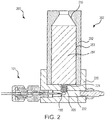
- FIG. 2 elements with like element numbering, as depicted in FIG. 1 , are intended to be the same and will not necessarily be repeated for the sake of clarity.
- Energetic ignition arrangement 200 may comprise ignition system arrangement 101.
- Energetic ignition arrangement 200 may comprise pressure vessel arrangement 202.
- Pressure vessel arrangement 202 may be coupled to ignition system arrangement 101.
- Pressure vessel arrangement 202 may comprise pressure vessel (also referred to herein as ignitor pressure vessel) 220.
- Ignitor pressure vessel 220 may define energetic cavity 222.
- Electric match 110 may extend into energetic cavity 222.
- Pressure vessel arrangement 202 may comprise propellant pressure vessel 252.
- Propellant pressure vessel 252 may define cavity (also referred to herein as a propellant cavity) 253.
- a propellant 254 may be disposed in propellant cavity 253.
- propellant 254 may comprise a solid fuel.
- An orifice 224 may be disposed in ignitor pressure vessel 220. Ignitor pressure vessel 220 may be coupled to propellant pressure vessel 252. Energetic cavity 222 may be in fluid communication with propellant cavity 253 via orifice 224. In this regard, electric match 110 may ignite and energetic 208 may ignite in response thereto. Energetic 208 may then ignite propellant 254.
- propellant 254 may define a nozzle 256 through which propellant 254 exhausts.
- various characteristics of propellant 254 may be characterized and/or tested including burn time, pressure, thrust, etc.
- pressure vessel arrangement 202 may comprise a rocket motor.
- ignition system arrangement 101 may be used for various other applications, including thrusters, pistons, actuators, or any other system which uses pressure.
- Energetic ignition arrangement 300 may comprise ignition system arrangement 101.
- Energetic ignition arrangement 300 may comprise pressure vessel arrangement 302.
- Pressure vessel arrangement 302 may be coupled to ignition system arrangement 101.
- Pressure vessel arrangement 302 may comprise pressure vessel (also referred to herein as ignitor pressure vessel) 320.
- Ignitor pressure vessel 320 may define energetic cavity 322.
- Electric match 110 may extend into energetic cavity 322.
- Pressure vessel arrangement 302 may comprise pressure vessel 352.
- Pressure vessel 352 may define cavity (also referred to herein as a piston cavity) 353.
- a piston 354 may be disposed in piston cavity 353.
- piston 354 may comprise a translatable piston configured to translate within piston cavity 353.
- An orifice 324 may be disposed in ignitor pressure vessel 320.
- Ignitor pressure vessel 320 may be coupled to pressure vessel 352.
- Energetic cavity 322 may be in fluid communication with piston cavity 353 via orifice 324.
- electric match 110 may ignite and energetic 308 may ignite in response thereto.
- Energetic 308 may increase a pressure P within chamber 356 to cause piston 354 to actuate or translate in the positive y-direction.
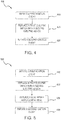
- Method 400 includes initiating a first ignition event (step 410).
- Method 400 includes replacing a first electric match with a second electric match (step 420).
- Method 500 includes initiating a second ignition event (step 430).
- step 410 may include supplying a current through wire leads 116 to ignite electric match 110 which ignites energetic 108 and/or energetic 208 in response thereto.
- Step 410 may occur at a first time.
- Step 420 may include replacing a first electric match 110 with a second electric match 110.
- Step 430 may comprise supplying a current through the second electric match 110 to initiate the second ignition event.
- ignitor housing 130, pressure vessel 120, pressure vessel 220, first ceramic isolator 144, second ceramic isolator 146, and/or seal 142 may be reusable after the energetic ignition arrangement has been employed in an ignition event.
- a method 500 for operating an energetic ignition arrangement may include replacing a seal with a replacement seal (i.e., a replacement seal) (step 525).
- the seal may comprise a replaceable seal.
- a method 600 for operating an energetic ignition arrangement may include replacing a first ceramic isolator with a replacement first ceramic isolator (step 627).
- Method 600 may further include replacing a second ceramic isolator with a replacement second ceramic isolator (step 629).
- first ceramic isolator 144 and second ceramic isolator 146 may comprise replaceable ceramic isolators.
- references to "one embodiment”, “an embodiment”, “various embodiments”, etc. indicate that the embodiment described may include a particular feature, structure, or characteristic, but every embodiment may not necessarily include the particular feature, structure, or characteristic. Moreover, such phrases are not necessarily referring to the same embodiment. Further, when a particular feature, structure, or characteristic is described in connection with an embodiment, it is submitted that it is within the knowledge of one skilled in the art to affect such feature, structure, or characteristic in connection with other embodiments whether or not explicitly described. After reading the description, it will be apparent to one skilled in the relevant art(s) how to implement the disclosure in alternative embodiments.
Landscapes
- Engineering & Computer Science (AREA)
- Chemical & Material Sciences (AREA)
- Combustion & Propulsion (AREA)
- Mechanical Engineering (AREA)
- General Engineering & Computer Science (AREA)
- Air Bags (AREA)
Abstract
Description
- The present disclosure relates generally to energetic systems, and more particularly, to a reusable system for energetics.
- Energetic systems may be used for various applications which use explosive energy to achieve a desired result. Testing and operating of energetic assemblies (rocket motors, test vessels, thrusters, actuators, etc.) use various samples of production hardware built, due to the inability to re-use ignition source and energetic materials. Ignition systems for pressure vessels may be entirely replaced after use due to the nature of the ignition system and ignition of the energetic therein.
- An energetic ignition arrangement is disclosed herein, in accordance with various embodiments. An energetic ignition arrangement may comprise a pressure vessel arrangement, comprising a pressure vessel, and an ignition system arrangement. The ignition system arrangement may comprise an ignitor housing coupled to the pressure vessel and defining a sealing aperture, a seal disposed in the sealing aperture, and an electric match extending through the ignitor housing, wherein at least the ignitor housing and the pressure vessel are reusable after the energetic ignition arrangement has been employed in an ignition event.
- In various embodiments, the electric match may extend through the seal. The electric match may comprise a heating element, an energetic compound coupled to the heating element, and at least one wire lead coupled to the heating element configured to supply electric power to the heating element. The seal may hermetically seal to the ignitor housing and to the at least one wire lead. The energetic ignition arrangement may further comprise a first ceramic isolator and a second ceramic isolator, wherein the first ceramic isolator and the second ceramic isolator electrically insulate the at least one wire lead, and wherein the seal is located between the first ceramic isolator and the second ceramic isolator. The pressure vessel may define a cavity within which the electric match is positionable. The electric match may be configured to ignite an energetic disposed in the cavity. The seal may comprise a polymeric material and the first ceramic isolator and the second ceramic isolator may comprise a ceramic material. At least one of the seal, the first ceramic isolator, and the second ceramic isolator may be reusable after the energetic ignition arrangement has been employed in the ignition event. The ignition system arrangement may further comprise a jam nut threadably coupled to the ignitor housing, and a follower disposed between the jam nut and the seal, wherein the seal is configured to be compressed between the follower and the ignitor housing in response to the jam nut being rotated relative to the ignitor housing.
- An energetic ignition arrangement is disclosed herein. An energetic ignition arrangement may comprise a pressure vessel arrangement, comprising an ignitor pressure vessel defining an energetic cavity, a propellant pressure vessel defining a propellant cavity, wherein the ignitor pressure vessel is coupled to the propellant pressure vessel, an energetic disposed in the energetic cavity, and a propellant disposed in the propellant pressure vessel, and an ignition system arrangement. The ignition system arrangement may comprise an ignitor housing coupled to the ignitor pressure vessel and defining a sealing aperture, a seal disposed in the sealing aperture configured to hermetically seals the ignitor housing, and an electric match extending through the ignitor housing, wherein at least the ignitor housing and the ignitor pressure vessel are reusable after the energetic ignition arrangement has been employed in an ignition event.
- In various embodiments, the electric match may extend through the seal. The electric match may comprise a heating element, an energetic compound coupled to the heating element, and at least one wire lead coupled to the heating element configured to supply electric power to the heating element. The energetic ignition arrangement may further comprise a first ceramic isolator and a second ceramic isolator, wherein the first ceramic isolator and the second ceramic isolator electrically insulate the at least one wire, and wherein the seal is located between the first ceramic isolator and the second ceramic isolator. The ignition event may comprise the electric match igniting the energetic and the energetic igniting the propellant in response to the electric match igniting the energetic. The seal may comprise a polymeric material and the first ceramic isolator and the second ceramic isolator may comprise a ceramic material. At least one of the seal, the first ceramic isolator, and the second ceramic isolator may be reusable after the energetic ignition arrangement has been employed in the ignition event. The ignition system arrangement may further comprise a jam nut coupled to the ignitor housing, and a follower disposed between the jam nut and the seal, wherein the seal is configured to be compressed between the follower and the ignitor housing in response to the jam nut being tightened.
- A method of operating an energetic ignition arrangement is disclosed. The energetic ignition arrangement may comprise a pressure vessel arrangement comprising a pressure vessel, and an ignition system arrangement comprising an ignitor housing coupled to the pressure vessel and defining a sealing aperture, a seal disposed in the sealing aperture, and an electric match extending through the ignitor housing The method may comprise initiating a first ignition event at a first time, comprising igniting the electric match, and igniting, by the electric match, an energetic, replacing the electric match with a second electric match, initiating a second ignition event at a second time, comprising igniting the second electric match, and igniting, by the second electric match, a second energetic.
- In various embodiments, the pressure vessel, the ignitor housing, and the seal may be used during the first ignition event and the second ignition event.
- The foregoing features and elements may be combined in various combinations without exclusivity, unless expressly indicated otherwise. These features and elements as well as the operation thereof will become more apparent in light of the following description and the accompanying drawings. It should be understood, however, the following description and drawings are intended to be exemplary in nature and non-limiting.
- The subject matter of the present disclosure is particularly pointed out and distinctly claimed in the concluding portion of the specification. A more complete understanding of the present disclosure, however, may best be obtained by referring to the detailed description and claims when considered in connection with the drawing figures.
-
FIG. 1 illustrates a cross section view of an energetic ignition arrangement, in accordance with various embodiments; -
FIG. 2 illustrates a cross section view of an energetic ignition arrangement coupled to a pressure vessel arrangement having a propellant, in accordance with various embodiments; -
FIG. 3 illustrates a cross section view of an energetic ignition arrangement coupled to a pressure vessel arrangement having a piston, in accordance with various embodiments; and -
FIGs. 4, 5 , and6 illustrate methods of operating an energetic ignition arrangement, in accordance with various embodiments. - The detailed description of various embodiments herein makes reference to the accompanying drawings, which show various embodiments by way of illustration. While these various embodiments are described in sufficient detail to enable those skilled in the art to practice the disclosure, it should be understood that other embodiments may be realized and that logical, chemical, and mechanical changes may be made without departing from the scope of the disclosure. Thus, the detailed description herein is presented for purposes of illustration only and not of limitation. For example, the steps recited in any of the method or process descriptions may be executed in any order and are not necessarily limited to the order presented.
- Furthermore, any reference to singular includes plural embodiments, and any reference to more than one component or step may include a singular embodiment or step. Also, any reference to attached, fixed, connected, or the like may include permanent, removable, temporary, partial, full, and/or any other possible attachment option. Additionally, any reference to without contact (or similar phrases) may also include reduced contact or minimal contact.
- As disclosed herein, an energetic ignition arrangement may comprise an electric match for igniting an energetic. The energetic ignition arrangement may be used for testing of various energetics. In this regard, it may be desirable to use energetic ignition arrangements various instances over a period of time. An ignition event may be initiated by igniting an electric match whereby the energetic is ignited. Various characteristics of the energetic may be the focus of testing or the energetic may be used to ignite an additional energetic such as a propellant, for example. In this regard, the energetic, the propellant, or the housings thereof may be tested during the ignition event. Furthermore, arrangements, as disclosed herein, may be for normal operation and are not limited to test systems.
- In various embodiments, an electric match may be a single-use item. In this regard, after an ignition event is complete, the electric match may be replaced with an additional electric match. The energetic may also be replaced, as well as the propellant. A seal is provided to hermetically seal an ignitor housing wherein the seal, as well as a portion of the electric match is disposed. In various embodiments, a first ceramic isolator and/or a second ceramic isolator. However, the seal may undergo several ignition events before being replaced. Replacement of the seal may be decided upon inspection of the seal. In this manner, an energetic ignition arrangement, as disclosed herein comprises a re-usable system. Energetic ignition arrangements, as disclosed herein, may provide a low cost testing system. Energetic ignition arrangements, as disclosed herein, may provide a testing system capable of quick, simple, and/or repeatable use.
- With reference to
FIG. 1 , anenergetic ignition arrangement 100 is depicted, in accordance with various embodiments.Energetic ignition arrangement 100 may include apressure vessel arrangement 102.Pressure vessel arrangement 102 may comprise apressure vessel 120.Pressure vessel 120 may define a cavity (also referred to herein as an energetic cavity) 122. An energetic 108 may be disposed inenergetic cavity 122. - In various embodiments, an energetic may comprise an explosive, a pyrotechnic composition, a propellant, a fuel, or the like. For example, energetic 108 may comprise a metal-oxidizer such as boron potassium nitrate (BKNO3). However, energetic 108 may comprise any suitable pyrotechnic composition, including metal hydride-oxidizers. Energetic 108 may comprise an ignitor. In this regard, energetic 108 may be used primarily to ignite other, more difficult to ignite materials (e.g., solid-fuel propellants). In various embodiments,
pressure vessel arrangement 102 may comprise a fitting 104 coupled topressure vessel 120. In various embodiments, fitting 104 may be detachably coupled topressure vessel 120. However, in various embodiments, fitting 104 andpressure vessel 120 may comprise a single, unitary member.Pressure vessel arrangement 102 may comprise apressure sensor 106.Pressure sensor 106 may detect a pressure withinenergetic cavity 122. For example,pressure sensor 106 may measure an increase in pressure withincavity 122 in response to energetic 108 being ignited. In this regard, various characteristics of energetic 108 may be characterized and/or tested including burn time, pressure, etc. -
Energetic ignition arrangement 100 may include anignition system arrangement 101.Ignition system arrangement 101 may compriseignitor housing 130.Ignitor housing 130 may define an aperture (also referred to herein as a sealing aperture) 138.Sealing aperture 138 may extend throughignitor housing 130 to create a hollow bore. Aseal 142 may be disposed within and seated against sealingaperture 138 to hermetically sealignitor housing 130.Ignitor housing 130 may be coupled to pressure vessel 210. In this regard,energetic cavity 122 may be hermetically sealed viaseal 142. A firstceramic isolator 144 and a secondceramic isolator 146 may be disposed within sealingaperture 138. In various embodiments,seal 142 may be located between firstceramic isolator 144 and secondceramic isolator 146.Seal 142 may comprise a polymeric material, such as a fluoroelastomer polymer for example, for high temperature usage.Seal 142 may comprise a polytetrafluoroethylene (PTFE). Firstceramic isolator 144 and secondceramic isolator 146 may comprise a ceramic material. Firstceramic isolator 144 and secondceramic isolator 146 may comprise porcelain, or any other electrically isolating material. Firstceramic isolator 144 and secondceramic isolator 146 may comprise a high temperature, high pressure ceramic. Firstceramic isolator 144 and secondceramic isolator 146 may comprise a high temperature ceramic such as an early transition metal boride, carbide, and/or nitride, such as hafnium nitride (HfN), zirconium nitride (ZrN), titanium carbide (TiC), titanium nitride (TiN), thorium dioxide (ThO2), and/ or tantalum carbide (TaC), for example. -
Ignition system arrangement 101 may comprise ajam nut 132 coupled toignitor housing 130. In various embodiments,jam nut 132 may be threadingly coupled toignitor housing 130. Afollower 134 may be disposed betweenjam nut 132 andseal 142.Follower 134 may comprise a hollow sleeve.Follower 134 may be disposed in sealingaperture 138.Seal 142 may be configured to be compressed betweenfollower 134 andignitor housing 130 in response tojam nut 132 being tightened. Stated differently, seal 142 may be configured to be compressed betweenfollower 134 andignitor housing 130 in response tojam nut 132 being rotated relative to ignitorhousing 130. Analignment pin 136 may be coupled betweenfollower 134 andignitor housing 130.Alignment pin 136 may preventfollower 134 from spinning in response tojam nut 132 being tightened. In this regard,alignment pin 136 may prevent seal 140 from spinning in response tojam nut 132 being tightened. In this regard,alignment pin 136 may preventelectric match 110 from spinning in response tojam nut 132 being tightened, which may prevent wire leads 116 from being tangled. -
Ignition system arrangement 101 may house an ignitor. In various embodiments,ignition system arrangement 101 houseselectric match 110.Electric match 110 may comprise an ignitor whereby an electric current is transformed into heat, which ignites an energetic compound.Electric match 110 may comprise wire leads 116 coupled to aheating element 114. Anelectric match head 112 may be coupled toheating element 114.Electric match head 112 may comprise theenergetic compound 113 configured to ignite in response to heat fromheating element 114.Electric match 110 may extend throughignitor housing 130.Electric match 110 may be positionable withinenergetic cavity 122.Electric match 110 may extend intoenergetic cavity 122.Electric match 110 may extend through seal 140. In various embodiments, wire leads 116 may extend throughseal 142, firstceramic isolator 144, and secondceramic isolator 146. Firstceramic isolator 144 and secondceramic isolator 146 may electrically isolate wire leads 116 from adjacent components ofignition system arrangement 101. Wire leads 116 may be sealed viaseal 142. Stated differently, seal 142 may hermetically seal to wire leads 116.Electric match head 112 may be in close proximity to energetic 108 such that ignition ofelectric match head 112 ignites energetic 108. - With respect to
FIG. 2 , elements with like element numbering, as depicted inFIG. 1 , are intended to be the same and will not necessarily be repeated for the sake of clarity. - With reference to
FIG. 2 , anenergetic ignition arrangement 200 is illustrated, in accordance with various embodiments.Energetic ignition arrangement 200 may compriseignition system arrangement 101.Energetic ignition arrangement 200 may comprisepressure vessel arrangement 202.Pressure vessel arrangement 202 may be coupled toignition system arrangement 101.Pressure vessel arrangement 202 may comprise pressure vessel (also referred to herein as ignitor pressure vessel) 220.Ignitor pressure vessel 220 may defineenergetic cavity 222.Electric match 110 may extend intoenergetic cavity 222.Pressure vessel arrangement 202 may comprisepropellant pressure vessel 252.Propellant pressure vessel 252 may define cavity (also referred to herein as a propellant cavity) 253. Apropellant 254 may be disposed inpropellant cavity 253. In various embodiments,propellant 254 may comprise a solid fuel. Anorifice 224 may be disposed inignitor pressure vessel 220.Ignitor pressure vessel 220 may be coupled topropellant pressure vessel 252.Energetic cavity 222 may be in fluid communication withpropellant cavity 253 viaorifice 224. In this regard,electric match 110 may ignite and energetic 208 may ignite in response thereto. Energetic 208 may then ignitepropellant 254. - In various embodiments,
propellant 254 may define anozzle 256 through whichpropellant 254 exhausts. In this regard, various characteristics ofpropellant 254 may be characterized and/or tested including burn time, pressure, thrust, etc. - In various embodiments,
pressure vessel arrangement 202 may comprise a rocket motor. However, it is contemplated herein thatignition system arrangement 101 may be used for various other applications, including thrusters, pistons, actuators, or any other system which uses pressure. - With reference to
FIG. 3 , anenergetic ignition arrangement 300 is illustrated, in accordance with various embodiments. Xy-axes are provided for ease of illustration.Energetic ignition arrangement 300 may compriseignition system arrangement 101.Energetic ignition arrangement 300 may comprisepressure vessel arrangement 302.Pressure vessel arrangement 302 may be coupled toignition system arrangement 101.Pressure vessel arrangement 302 may comprise pressure vessel (also referred to herein as ignitor pressure vessel) 320.Ignitor pressure vessel 320 may defineenergetic cavity 322.Electric match 110 may extend intoenergetic cavity 322.Pressure vessel arrangement 302 may comprisepressure vessel 352.Pressure vessel 352 may define cavity (also referred to herein as a piston cavity) 353. Apiston 354 may be disposed inpiston cavity 353. In various embodiments,piston 354 may comprise a translatable piston configured to translate withinpiston cavity 353. Anorifice 324 may be disposed inignitor pressure vessel 320.Ignitor pressure vessel 320 may be coupled topressure vessel 352.Energetic cavity 322 may be in fluid communication withpiston cavity 353 viaorifice 324. In this regard,electric match 110 may ignite and energetic 308 may ignite in response thereto. Energetic 308 may increase a pressure P withinchamber 356 to causepiston 354 to actuate or translate in the positive y-direction. - With reference to
FIG. 4 , amethod 400 for operating an energetic ignition arrangement is depicted, in accordance with various embodiments.Method 400 includes initiating a first ignition event (step 410).Method 400 includes replacing a first electric match with a second electric match (step 420).Method 500 includes initiating a second ignition event (step 430). - With reference to
FIG. 1 ,FIG. 2 , andFIG. 4 , step 410 may include supplying a current through wire leads 116 to igniteelectric match 110 which ignites energetic 108 and/or energetic 208 in response thereto. Step 410 may occur at a first time. Step 420 may include replacing a firstelectric match 110 with a secondelectric match 110. Step 430 may comprise supplying a current through the secondelectric match 110 to initiate the second ignition event. In this regard,ignitor housing 130,pressure vessel 120,pressure vessel 220, firstceramic isolator 144, secondceramic isolator 146, and/or seal 142 may be reusable after the energetic ignition arrangement has been employed in an ignition event. - With respect to
FIG. 5 , elements with like element numbering, as depicted inFIG. 4 , are intended to be the same and will not necessarily be repeated for the sake of clarity. - In various embodiments, upon inspection, it may be desirable to replace
seal 142 with areplacement seal 142. In this regard, with reference toFIG. 5 , amethod 500 for operating an energetic ignition arrangement may include replacing a seal with a replacement seal (i.e., a replacement seal) (step 525). In this regard, the seal may comprise a replaceable seal. - With respect to
FIG. 6 , elements with like element numbering, as depicted inFIG. 5 , are intended to be the same and will not necessarily be repeated for the sake of clarity. - In various embodiments, upon inspection, it may be desirable to replace first
ceramic isolator 144 and/or secondceramic isolator 146 with a replacement ceramic isolator. In this regard, with reference toFIG. 6 , amethod 600 for operating an energetic ignition arrangement may include replacing a first ceramic isolator with a replacement first ceramic isolator (step 627).Method 600 may further include replacing a second ceramic isolator with a replacement second ceramic isolator (step 629). In this regard, firstceramic isolator 144 and secondceramic isolator 146 may comprise replaceable ceramic isolators. - Benefits, other advantages, and solutions to problems have been described herein with regard to specific embodiments. Furthermore, the connecting lines shown in the various figures contained herein are intended to represent exemplary functional relationships and/or physical couplings between the various elements. It should be noted that many alternative or additional functional relationships or physical connections may be present in a practical system. However, the benefits, advantages, solutions to problems, and any elements that may cause any benefit, advantage, or solution to occur or become more pronounced are not to be construed as critical, required, or essential features or elements of the disclosure. The scope of the disclosure is accordingly to be limited by nothing other than the appended claims, in which reference to an element in the singular is not intended to mean "one and only one" unless explicitly so stated, but rather "one or more." Moreover, where a phrase similar to "at least one of A, B, or C" is used in the claims, it is intended that the phrase be interpreted to mean that A alone may be present in an embodiment, B alone may be present in an embodiment, C alone may be present in an embodiment, or that any combination of the elements A, B and C may be present in a single embodiment; for example, A and B, A and C, B and C, or A and B and C. Different cross-hatching is used throughout the figures to denote different parts but not necessarily to denote the same or different materials.
- Systems, methods and apparatus are provided herein. In the detailed description herein, references to "one embodiment", "an embodiment", "various embodiments", etc., indicate that the embodiment described may include a particular feature, structure, or characteristic, but every embodiment may not necessarily include the particular feature, structure, or characteristic. Moreover, such phrases are not necessarily referring to the same embodiment. Further, when a particular feature, structure, or characteristic is described in connection with an embodiment, it is submitted that it is within the knowledge of one skilled in the art to affect such feature, structure, or characteristic in connection with other embodiments whether or not explicitly described. After reading the description, it will be apparent to one skilled in the relevant art(s) how to implement the disclosure in alternative embodiments.
Claims (15)
- An energetic ignition arrangement, comprising:a pressure vessel arrangement (102), comprising:a pressure vessel (120); andan ignition system arrangement (101), comprising:an ignitor housing (130) coupled to the pressure vessel and defining a sealing aperture (138);a seal (142) disposed in the sealing aperture; andan electric match (110) extending through the ignitor housing,wherein at least the ignitor housing and the pressure vessel are reusable after the energetic ignition arrangement has been employed in an ignition event.
- An energetic ignition arrangement, comprising:a pressure vessel arrangement, comprising:an ignitor pressure vessel (220) defining an energetic cavity (222);a propellant pressure vessel (252) defining a propellant cavity (253),wherein the ignitor pressure vessel is coupled to the propellant pressure vessel;an energetic (208) disposed in the energetic cavity; anda propellant (254) disposed in the propellant pressure vessel; andan ignition system arrangement, comprising:an ignitor housing (130) coupled to the ignitor pressure vessel and defining a sealing aperture (138);a seal (142) disposed in the sealing aperture configured to hermetically seals the ignitor housing; andan electric match (110) extending through the ignitor housing,wherein at least the ignitor housing and the ignitor pressure vessel are reusable after the energetic ignition arrangement has been employed in an ignition event.
- The energetic ignition arrangement of claim 1 or 2, wherein the electric match extends through the seal.
- The energetic ignition arrangement of claim 3, wherein the electric match comprises:a heating element;an energetic compound coupled to the heating element; andat least one wire lead coupled to the heating element configured to supply electric power to the heating element.
- The energetic ignition arrangement of claim 4, wherein the seal hermetically seals to the ignitor housing and to the at least one wire lead.
- The energetic ignition arrangement of claim 5, wherein the pressure vessel defines a cavity (122) within which the electric match is positionable.
- The energetic ignition arrangement of claim 6, wherein the electric match is configured to ignite an energetic disposed in the cavity.
- The energetic ignition arrangement of any preceding claim, further comprising a first ceramic isolator (144) and a second ceramic isolator (146);
wherein the first ceramic isolator and the second ceramic isolator electrically insulate the at least one wire; and
wherein the seal is located between the first ceramic isolator and the second ceramic isolator. - The energetic ignition arrangement of claim 8, wherein the seal comprises a polymeric material and the first ceramic isolator and the second ceramic isolator comprise a ceramic material.
- The energetic ignition arrangement of claim 8, wherein at least one of the seal, the first ceramic isolator, and the second ceramic isolator are reusable after the energetic ignition arrangement has been employed in the ignition event.
- The energetic ignition arrangement of claim 8, wherein the ignition event comprises the electric match igniting the energetic and the energetic igniting the propellant in response to the electric match igniting the energetic.
- The energetic ignition arrangement of claim 11, wherein the seal comprises a polymeric material and the first ceramic isolator and the second ceramic isolator comprise a ceramic material.
- The energetic ignition arrangement of claim 11, wherein at least one of the seal, the first ceramic isolator, and the second ceramic isolator are reusable after the energetic ignition arrangement has been employed in the ignition event.
- The energetic ignition arrangement of claim 8, wherein the ignition system arrangement further comprises:a jam nut (132) coupled to the ignitor housing; anda follower (134) disposed between the jam nut and the seal,wherein the seal is configured to be compressed between the follower and the ignitor housing in response to the jam nut being tightened.
- A method of operating an energetic ignition arrangement, comprising:a pressure vessel arrangement, comprising:a pressure vessel; andan ignition system arrangement, comprising:an ignitor housing coupled to the pressure vessel and defining a sealing aperture;a seal disposed in the sealing aperture; andan electric match extending through the ignitor housing,the method comprising:initiating a first ignition event at a first time, comprising:igniting the electric match; andigniting, by the electric match, an energetic;replacing the electric match with a second electric match;initiating a second ignition event at a second time, comprising:igniting the second electric match; andigniting, by the second electric match, a second energetic.
Applications Claiming Priority (1)
| Application Number | Priority Date | Filing Date | Title |
|---|---|---|---|
| US15/426,861 US10443545B2 (en) | 2017-02-07 | 2017-02-07 | Reusable high pressure and high temperature energetic ignition system |
Publications (2)
| Publication Number | Publication Date |
|---|---|
| EP3392495A1 true EP3392495A1 (en) | 2018-10-24 |
| EP3392495B1 EP3392495B1 (en) | 2020-12-23 |
Family
ID=61188608
Family Applications (1)
| Application Number | Title | Priority Date | Filing Date |
|---|---|---|---|
| EP18155450.2A Active EP3392495B1 (en) | 2017-02-07 | 2018-02-07 | Reusable high pressure and high temperature energetic ignition system |
Country Status (2)
| Country | Link |
|---|---|
| US (1) | US10443545B2 (en) |
| EP (1) | EP3392495B1 (en) |
Families Citing this family (4)
| Publication number | Priority date | Publication date | Assignee | Title |
|---|---|---|---|---|
| US11512645B2 (en) | 2020-03-06 | 2022-11-29 | Goodrich Corporation | Solid-propellant gas generator assemblies and methods |
| CN113847167B (en) * | 2021-08-31 | 2023-02-03 | 上海新力动力设备研究所 | Wire fixing combined mechanism for ignition device of solid rocket engine |
| CN116717399B (en) * | 2023-05-24 | 2025-12-05 | 中国人民解放军国防科技大学 | A pressure-sensing ignition device and a rocket model |
| CN118757281B (en) * | 2024-07-22 | 2025-12-19 | 北京流体动力科学研究中心 | A ground-floating combustion chamber igniter |
Citations (2)
| Publication number | Priority date | Publication date | Assignee | Title |
|---|---|---|---|---|
| US2493725A (en) * | 1946-06-24 | 1950-01-03 | Helen C Mcmorris | Partial burning apparatus |
| US3988989A (en) * | 1975-09-10 | 1976-11-02 | The United States Of America As Represented By The Secretary Of The Navy | High-pressure, electrically initiated explosive igniter |
Family Cites Families (10)
| Publication number | Priority date | Publication date | Assignee | Title |
|---|---|---|---|---|
| US2934014A (en) | 1956-12-06 | 1960-04-26 | Rex L Smith | Igniter assemblies |
| SE431590B (en) | 1979-09-03 | 1984-02-13 | Bofors Ab | CONTACT WITH HIGH FREQUENCY FILTER FOR AN ELECTRIC TENDER |
| US4378674A (en) | 1981-03-26 | 1983-04-05 | Thiokol Corporation | Variable aperture annular nozzle for rocket motor igniter |
| US4856433A (en) * | 1987-07-13 | 1989-08-15 | Scot, Incorporated | Initiator device with adiabatic compression ignition |
| US5715675A (en) * | 1994-10-21 | 1998-02-10 | Environmental Aeroscience Corp. | Hybrid rocket system and integrated motor for use therein |
| US6016652A (en) * | 1994-10-21 | 2000-01-25 | Hy-Pat Corporation | Hybrid rocket system with disposable cartridge |
| US5579636A (en) * | 1995-03-21 | 1996-12-03 | Aerotech, Inc. | Pyrotechnic valve, igniter and combustion preheater for hybrid rocket motors |
| ZA200200808B (en) * | 2001-03-22 | 2002-08-12 | Roche Diagnostics Gmbh | Needleless hypodermic injection system, application device and medication cartridge therefor. |
| US20040162517A1 (en) * | 2002-12-04 | 2004-08-19 | Otto Furst | Needleless hydpodermic injection device with non-electric ignition means |
| US9273635B2 (en) * | 2012-03-29 | 2016-03-01 | The Aerospace Corporation | Hypergolic hybrid motor igniter |
-
2017
- 2017-02-07 US US15/426,861 patent/US10443545B2/en active Active
-
2018
- 2018-02-07 EP EP18155450.2A patent/EP3392495B1/en active Active
Patent Citations (2)
| Publication number | Priority date | Publication date | Assignee | Title |
|---|---|---|---|---|
| US2493725A (en) * | 1946-06-24 | 1950-01-03 | Helen C Mcmorris | Partial burning apparatus |
| US3988989A (en) * | 1975-09-10 | 1976-11-02 | The United States Of America As Represented By The Secretary Of The Navy | High-pressure, electrically initiated explosive igniter |
Also Published As
| Publication number | Publication date |
|---|---|
| US20180223772A1 (en) | 2018-08-09 |
| US10443545B2 (en) | 2019-10-15 |
| EP3392495B1 (en) | 2020-12-23 |
Similar Documents
| Publication | Publication Date | Title |
|---|---|---|
| EP3392495B1 (en) | Reusable high pressure and high temperature energetic ignition system | |
| US3119302A (en) | Gas sealed explosive propelling arrangement | |
| CN103697935B (en) | Bottom row propellant transient pressure relief combustion instability characteristics test device | |
| CN107100761B (en) | a test engine | |
| US20190249970A1 (en) | High explosive firing mechanism | |
| CN110925099B (en) | Ignition electric nozzle with replaceable ignition nozzle component and installation method thereof | |
| US3270668A (en) | Well-treating apparatus | |
| US10320156B2 (en) | Spark plug and method for manufacturing same | |
| CN109580697A (en) | Gun tube material ablation experimental rig and method | |
| US5081862A (en) | Apparatus and method for pressure testing closure disks | |
| US20240288087A1 (en) | Restorable pyrotechnic valve | |
| US7117796B1 (en) | Igniter for exothermic torch rod | |
| KR100661749B1 (en) | Object coupling-separating device | |
| US6672215B2 (en) | Constant output high-precision microcapillary pyrotechnic initiator | |
| CN112881229B (en) | A solid propellant high-pressure flameout burning surface acquisition device and acquisition method | |
| RU2428581C1 (en) | Testing method and device of solid-propellant rocket engine | |
| US2713768A (en) | Power gas generating assemblies | |
| EP3527930A1 (en) | Low energy explosive transfer adapter | |
| EP3646362B1 (en) | Actuator | |
| CN115561387A (en) | A device and method for continuously igniting propellant combustion energy performance test | |
| JP7034167B2 (en) | Actuator | |
| US11512645B2 (en) | Solid-propellant gas generator assemblies and methods | |
| US2367012A (en) | Cartridge firing apparatus for power generation | |
| US5259417A (en) | Device for testing closure disks at high rates of change of pressure | |
| CN121322257A (en) | Test device convenient to change test point firearm operating characteristic of free volume |
Legal Events
| Date | Code | Title | Description |
|---|---|---|---|
| PUAI | Public reference made under article 153(3) epc to a published international application that has entered the european phase |
Free format text: ORIGINAL CODE: 0009012 |
|
| STAA | Information on the status of an ep patent application or granted ep patent |
Free format text: STATUS: THE APPLICATION HAS BEEN PUBLISHED |
|
| AK | Designated contracting states |
Kind code of ref document: A1 Designated state(s): AL AT BE BG CH CY CZ DE DK EE ES FI FR GB GR HR HU IE IS IT LI LT LU LV MC MK MT NL NO PL PT RO RS SE SI SK SM TR |
|
| AX | Request for extension of the european patent |
Extension state: BA ME |
|
| STAA | Information on the status of an ep patent application or granted ep patent |
Free format text: STATUS: REQUEST FOR EXAMINATION WAS MADE |
|
| 17P | Request for examination filed |
Effective date: 20190424 |
|
| RBV | Designated contracting states (corrected) |
Designated state(s): AL AT BE BG CH CY CZ DE DK EE ES FI FR GB GR HR HU IE IS IT LI LT LU LV MC MK MT NL NO PL PT RO RS SE SI SK SM TR |
|
| GRAP | Despatch of communication of intention to grant a patent |
Free format text: ORIGINAL CODE: EPIDOSNIGR1 |
|
| STAA | Information on the status of an ep patent application or granted ep patent |
Free format text: STATUS: GRANT OF PATENT IS INTENDED |
|
| RIC1 | Information provided on ipc code assigned before grant |
Ipc: F02K 9/96 20060101AFI20200625BHEP |
|
| INTG | Intention to grant announced |
Effective date: 20200717 |
|
| GRAS | Grant fee paid |
Free format text: ORIGINAL CODE: EPIDOSNIGR3 |
|
| GRAA | (expected) grant |
Free format text: ORIGINAL CODE: 0009210 |
|
| STAA | Information on the status of an ep patent application or granted ep patent |
Free format text: STATUS: THE PATENT HAS BEEN GRANTED |
|
| AK | Designated contracting states |
Kind code of ref document: B1 Designated state(s): AL AT BE BG CH CY CZ DE DK EE ES FI FR GB GR HR HU IE IS IT LI LT LU LV MC MK MT NL NO PL PT RO RS SE SI SK SM TR |
|
| REG | Reference to a national code |
Ref country code: GB Ref legal event code: FG4D |
|
| REG | Reference to a national code |
Ref country code: DE Ref legal event code: R096 Ref document number: 602018010956 Country of ref document: DE |
|
| REG | Reference to a national code |
Ref country code: AT Ref legal event code: REF Ref document number: 1347953 Country of ref document: AT Kind code of ref document: T Effective date: 20210115 |
|
| REG | Reference to a national code |
Ref country code: IE Ref legal event code: FG4D |
|
| PG25 | Lapsed in a contracting state [announced via postgrant information from national office to epo] |
Ref country code: RS Free format text: LAPSE BECAUSE OF FAILURE TO SUBMIT A TRANSLATION OF THE DESCRIPTION OR TO PAY THE FEE WITHIN THE PRESCRIBED TIME-LIMIT Effective date: 20201223 Ref country code: FI Free format text: LAPSE BECAUSE OF FAILURE TO SUBMIT A TRANSLATION OF THE DESCRIPTION OR TO PAY THE FEE WITHIN THE PRESCRIBED TIME-LIMIT Effective date: 20201223 Ref country code: NO Free format text: LAPSE BECAUSE OF FAILURE TO SUBMIT A TRANSLATION OF THE DESCRIPTION OR TO PAY THE FEE WITHIN THE PRESCRIBED TIME-LIMIT Effective date: 20210323 Ref country code: GR Free format text: LAPSE BECAUSE OF FAILURE TO SUBMIT A TRANSLATION OF THE DESCRIPTION OR TO PAY THE FEE WITHIN THE PRESCRIBED TIME-LIMIT Effective date: 20210324 |
|
| REG | Reference to a national code |
Ref country code: AT Ref legal event code: MK05 Ref document number: 1347953 Country of ref document: AT Kind code of ref document: T Effective date: 20201223 |
|
| REG | Reference to a national code |
Ref country code: NL Ref legal event code: MP Effective date: 20201223 |
|
| PG25 | Lapsed in a contracting state [announced via postgrant information from national office to epo] |
Ref country code: BG Free format text: LAPSE BECAUSE OF FAILURE TO SUBMIT A TRANSLATION OF THE DESCRIPTION OR TO PAY THE FEE WITHIN THE PRESCRIBED TIME-LIMIT Effective date: 20210323 Ref country code: LV Free format text: LAPSE BECAUSE OF FAILURE TO SUBMIT A TRANSLATION OF THE DESCRIPTION OR TO PAY THE FEE WITHIN THE PRESCRIBED TIME-LIMIT Effective date: 20201223 Ref country code: SE Free format text: LAPSE BECAUSE OF FAILURE TO SUBMIT A TRANSLATION OF THE DESCRIPTION OR TO PAY THE FEE WITHIN THE PRESCRIBED TIME-LIMIT Effective date: 20201223 |
|
| PG25 | Lapsed in a contracting state [announced via postgrant information from national office to epo] |
Ref country code: NL Free format text: LAPSE BECAUSE OF FAILURE TO SUBMIT A TRANSLATION OF THE DESCRIPTION OR TO PAY THE FEE WITHIN THE PRESCRIBED TIME-LIMIT Effective date: 20201223 Ref country code: HR Free format text: LAPSE BECAUSE OF FAILURE TO SUBMIT A TRANSLATION OF THE DESCRIPTION OR TO PAY THE FEE WITHIN THE PRESCRIBED TIME-LIMIT Effective date: 20201223 |
|
| REG | Reference to a national code |
Ref country code: LT Ref legal event code: MG9D |
|
| PG25 | Lapsed in a contracting state [announced via postgrant information from national office to epo] |
Ref country code: PT Free format text: LAPSE BECAUSE OF FAILURE TO SUBMIT A TRANSLATION OF THE DESCRIPTION OR TO PAY THE FEE WITHIN THE PRESCRIBED TIME-LIMIT Effective date: 20210423 Ref country code: RO Free format text: LAPSE BECAUSE OF FAILURE TO SUBMIT A TRANSLATION OF THE DESCRIPTION OR TO PAY THE FEE WITHIN THE PRESCRIBED TIME-LIMIT Effective date: 20201223 Ref country code: SK Free format text: LAPSE BECAUSE OF FAILURE TO SUBMIT A TRANSLATION OF THE DESCRIPTION OR TO PAY THE FEE WITHIN THE PRESCRIBED TIME-LIMIT Effective date: 20201223 Ref country code: SM Free format text: LAPSE BECAUSE OF FAILURE TO SUBMIT A TRANSLATION OF THE DESCRIPTION OR TO PAY THE FEE WITHIN THE PRESCRIBED TIME-LIMIT Effective date: 20201223 Ref country code: LT Free format text: LAPSE BECAUSE OF FAILURE TO SUBMIT A TRANSLATION OF THE DESCRIPTION OR TO PAY THE FEE WITHIN THE PRESCRIBED TIME-LIMIT Effective date: 20201223 Ref country code: EE Free format text: LAPSE BECAUSE OF FAILURE TO SUBMIT A TRANSLATION OF THE DESCRIPTION OR TO PAY THE FEE WITHIN THE PRESCRIBED TIME-LIMIT Effective date: 20201223 Ref country code: CZ Free format text: LAPSE BECAUSE OF FAILURE TO SUBMIT A TRANSLATION OF THE DESCRIPTION OR TO PAY THE FEE WITHIN THE PRESCRIBED TIME-LIMIT Effective date: 20201223 |
|
| PG25 | Lapsed in a contracting state [announced via postgrant information from national office to epo] |
Ref country code: PL Free format text: LAPSE BECAUSE OF FAILURE TO SUBMIT A TRANSLATION OF THE DESCRIPTION OR TO PAY THE FEE WITHIN THE PRESCRIBED TIME-LIMIT Effective date: 20201223 Ref country code: AT Free format text: LAPSE BECAUSE OF FAILURE TO SUBMIT A TRANSLATION OF THE DESCRIPTION OR TO PAY THE FEE WITHIN THE PRESCRIBED TIME-LIMIT Effective date: 20201223 |
|
| REG | Reference to a national code |
Ref country code: DE Ref legal event code: R119 Ref document number: 602018010956 Country of ref document: DE |
|
| PG25 | Lapsed in a contracting state [announced via postgrant information from national office to epo] |
Ref country code: IS Free format text: LAPSE BECAUSE OF FAILURE TO SUBMIT A TRANSLATION OF THE DESCRIPTION OR TO PAY THE FEE WITHIN THE PRESCRIBED TIME-LIMIT Effective date: 20210423 Ref country code: MC Free format text: LAPSE BECAUSE OF FAILURE TO SUBMIT A TRANSLATION OF THE DESCRIPTION OR TO PAY THE FEE WITHIN THE PRESCRIBED TIME-LIMIT Effective date: 20201223 |
|
| REG | Reference to a national code |
Ref country code: BE Ref legal event code: MM Effective date: 20210228 |
|
| PG25 | Lapsed in a contracting state [announced via postgrant information from national office to epo] |
Ref country code: AL Free format text: LAPSE BECAUSE OF FAILURE TO SUBMIT A TRANSLATION OF THE DESCRIPTION OR TO PAY THE FEE WITHIN THE PRESCRIBED TIME-LIMIT Effective date: 20201223 Ref country code: CH Free format text: LAPSE BECAUSE OF NON-PAYMENT OF DUE FEES Effective date: 20210228 Ref country code: LU Free format text: LAPSE BECAUSE OF NON-PAYMENT OF DUE FEES Effective date: 20210207 Ref country code: IT Free format text: LAPSE BECAUSE OF FAILURE TO SUBMIT A TRANSLATION OF THE DESCRIPTION OR TO PAY THE FEE WITHIN THE PRESCRIBED TIME-LIMIT Effective date: 20201223 Ref country code: LI Free format text: LAPSE BECAUSE OF NON-PAYMENT OF DUE FEES Effective date: 20210228 |
|
| PLBE | No opposition filed within time limit |
Free format text: ORIGINAL CODE: 0009261 |
|
| STAA | Information on the status of an ep patent application or granted ep patent |
Free format text: STATUS: NO OPPOSITION FILED WITHIN TIME LIMIT |
|
| PG25 | Lapsed in a contracting state [announced via postgrant information from national office to epo] |
Ref country code: DK Free format text: LAPSE BECAUSE OF FAILURE TO SUBMIT A TRANSLATION OF THE DESCRIPTION OR TO PAY THE FEE WITHIN THE PRESCRIBED TIME-LIMIT Effective date: 20201223 |
|
| 26N | No opposition filed |
Effective date: 20210924 |
|
| PG25 | Lapsed in a contracting state [announced via postgrant information from national office to epo] |
Ref country code: DE Free format text: LAPSE BECAUSE OF NON-PAYMENT OF DUE FEES Effective date: 20210901 Ref country code: ES Free format text: LAPSE BECAUSE OF FAILURE TO SUBMIT A TRANSLATION OF THE DESCRIPTION OR TO PAY THE FEE WITHIN THE PRESCRIBED TIME-LIMIT Effective date: 20201223 Ref country code: IE Free format text: LAPSE BECAUSE OF NON-PAYMENT OF DUE FEES Effective date: 20210207 Ref country code: FR Free format text: LAPSE BECAUSE OF NON-PAYMENT OF DUE FEES Effective date: 20210223 |
|
| PG25 | Lapsed in a contracting state [announced via postgrant information from national office to epo] |
Ref country code: SI Free format text: LAPSE BECAUSE OF FAILURE TO SUBMIT A TRANSLATION OF THE DESCRIPTION OR TO PAY THE FEE WITHIN THE PRESCRIBED TIME-LIMIT Effective date: 20201223 |
|
| PG25 | Lapsed in a contracting state [announced via postgrant information from national office to epo] |
Ref country code: IS Free format text: LAPSE BECAUSE OF FAILURE TO SUBMIT A TRANSLATION OF THE DESCRIPTION OR TO PAY THE FEE WITHIN THE PRESCRIBED TIME-LIMIT Effective date: 20210423 |
|
| PG25 | Lapsed in a contracting state [announced via postgrant information from national office to epo] |
Ref country code: BE Free format text: LAPSE BECAUSE OF NON-PAYMENT OF DUE FEES Effective date: 20210228 |
|
| PG25 | Lapsed in a contracting state [announced via postgrant information from national office to epo] |
Ref country code: CY Free format text: LAPSE BECAUSE OF FAILURE TO SUBMIT A TRANSLATION OF THE DESCRIPTION OR TO PAY THE FEE WITHIN THE PRESCRIBED TIME-LIMIT Effective date: 20201223 |
|
| PG25 | Lapsed in a contracting state [announced via postgrant information from national office to epo] |
Ref country code: HU Free format text: LAPSE BECAUSE OF FAILURE TO SUBMIT A TRANSLATION OF THE DESCRIPTION OR TO PAY THE FEE WITHIN THE PRESCRIBED TIME-LIMIT; INVALID AB INITIO Effective date: 20180207 |
|
| PG25 | Lapsed in a contracting state [announced via postgrant information from national office to epo] |
Ref country code: MK Free format text: LAPSE BECAUSE OF FAILURE TO SUBMIT A TRANSLATION OF THE DESCRIPTION OR TO PAY THE FEE WITHIN THE PRESCRIBED TIME-LIMIT Effective date: 20201223 |
|
| PG25 | Lapsed in a contracting state [announced via postgrant information from national office to epo] |
Ref country code: TR Free format text: LAPSE BECAUSE OF FAILURE TO SUBMIT A TRANSLATION OF THE DESCRIPTION OR TO PAY THE FEE WITHIN THE PRESCRIBED TIME-LIMIT Effective date: 20201223 |
|
| PG25 | Lapsed in a contracting state [announced via postgrant information from national office to epo] |
Ref country code: MT Free format text: LAPSE BECAUSE OF FAILURE TO SUBMIT A TRANSLATION OF THE DESCRIPTION OR TO PAY THE FEE WITHIN THE PRESCRIBED TIME-LIMIT Effective date: 20201223 |
|
| P01 | Opt-out of the competence of the unified patent court (upc) registered |
Free format text: CASE NUMBER: UPC_APP_0017164_3392495/2025 Effective date: 20251211 |
|
| PGFP | Annual fee paid to national office [announced via postgrant information from national office to epo] |
Ref country code: GB Payment date: 20260121 Year of fee payment: 9 |