EP3392399A1 - Dryer - Google Patents
Dryer Download PDFInfo
- Publication number
- EP3392399A1 EP3392399A1 EP16874912.5A EP16874912A EP3392399A1 EP 3392399 A1 EP3392399 A1 EP 3392399A1 EP 16874912 A EP16874912 A EP 16874912A EP 3392399 A1 EP3392399 A1 EP 3392399A1
- Authority
- EP
- European Patent Office
- Prior art keywords
- temperature
- ignition
- drum
- clothes
- exhaust
- Prior art date
- Legal status (The legal status is an assumption and is not a legal conclusion. Google has not performed a legal analysis and makes no representation as to the accuracy of the status listed.)
- Granted
Links
- 238000010438 heat treatment Methods 0.000 claims abstract description 47
- 238000001035 drying Methods 0.000 claims abstract description 37
- 238000012545 processing Methods 0.000 claims abstract description 37
- 238000007599 discharging Methods 0.000 claims abstract description 4
- 238000001514 detection method Methods 0.000 claims description 8
- 238000012937 correction Methods 0.000 claims description 5
- 238000013021 overheating Methods 0.000 abstract description 8
- 238000000034 method Methods 0.000 description 31
- 230000008569 process Effects 0.000 description 20
- 238000010981 drying operation Methods 0.000 description 17
- 238000005192 partition Methods 0.000 description 12
- 238000009423 ventilation Methods 0.000 description 8
- 238000002485 combustion reaction Methods 0.000 description 5
- 230000000694 effects Effects 0.000 description 5
- 230000003247 decreasing effect Effects 0.000 description 3
- 238000004519 manufacturing process Methods 0.000 description 3
- 230000008033 biological extinction Effects 0.000 description 2
- 230000007423 decrease Effects 0.000 description 2
- 238000010586 diagram Methods 0.000 description 2
- 238000002474 experimental method Methods 0.000 description 2
- 230000009467 reduction Effects 0.000 description 2
- 238000003303 reheating Methods 0.000 description 2
- 208000034656 Contusions Diseases 0.000 description 1
- 230000002159 abnormal effect Effects 0.000 description 1
- 208000034526 bruise Diseases 0.000 description 1
- 230000008859 change Effects 0.000 description 1
- 230000001186 cumulative effect Effects 0.000 description 1
- 238000001704 evaporation Methods 0.000 description 1
- 230000008020 evaporation Effects 0.000 description 1
- 239000004744 fabric Substances 0.000 description 1
- 230000006872 improvement Effects 0.000 description 1
- 238000012986 modification Methods 0.000 description 1
- 230000004048 modification Effects 0.000 description 1
- 230000000630 rising effect Effects 0.000 description 1
- 235000015096 spirit Nutrition 0.000 description 1
- XLYOFNOQVPJJNP-UHFFFAOYSA-N water Substances O XLYOFNOQVPJJNP-UHFFFAOYSA-N 0.000 description 1
Images



Classifications
-
- D—TEXTILES; PAPER
- D06—TREATMENT OF TEXTILES OR THE LIKE; LAUNDERING; FLEXIBLE MATERIALS NOT OTHERWISE PROVIDED FOR
- D06F—LAUNDERING, DRYING, IRONING, PRESSING OR FOLDING TEXTILE ARTICLES
- D06F58/00—Domestic laundry dryers
- D06F58/32—Control of operations performed in domestic laundry dryers
- D06F58/34—Control of operations performed in domestic laundry dryers characterised by the purpose or target of the control
- D06F58/36—Control of operational steps, e.g. for optimisation or improvement of operational steps depending on the condition of the laundry
- D06F58/38—Control of operational steps, e.g. for optimisation or improvement of operational steps depending on the condition of the laundry of drying, e.g. to achieve the target humidity
-
- D—TEXTILES; PAPER
- D06—TREATMENT OF TEXTILES OR THE LIKE; LAUNDERING; FLEXIBLE MATERIALS NOT OTHERWISE PROVIDED FOR
- D06F—LAUNDERING, DRYING, IRONING, PRESSING OR FOLDING TEXTILE ARTICLES
- D06F2103/00—Parameters monitored or detected for the control of domestic laundry washing machines, washer-dryers or laundry dryers
- D06F2103/02—Characteristics of laundry or load
- D06F2103/08—Humidity
-
- D—TEXTILES; PAPER
- D06—TREATMENT OF TEXTILES OR THE LIKE; LAUNDERING; FLEXIBLE MATERIALS NOT OTHERWISE PROVIDED FOR
- D06F—LAUNDERING, DRYING, IRONING, PRESSING OR FOLDING TEXTILE ARTICLES
- D06F2103/00—Parameters monitored or detected for the control of domestic laundry washing machines, washer-dryers or laundry dryers
- D06F2103/28—Air properties
- D06F2103/32—Temperature
-
- D—TEXTILES; PAPER
- D06—TREATMENT OF TEXTILES OR THE LIKE; LAUNDERING; FLEXIBLE MATERIALS NOT OTHERWISE PROVIDED FOR
- D06F—LAUNDERING, DRYING, IRONING, PRESSING OR FOLDING TEXTILE ARTICLES
- D06F2103/00—Parameters monitored or detected for the control of domestic laundry washing machines, washer-dryers or laundry dryers
- D06F2103/38—Time, e.g. duration
-
- D—TEXTILES; PAPER
- D06—TREATMENT OF TEXTILES OR THE LIKE; LAUNDERING; FLEXIBLE MATERIALS NOT OTHERWISE PROVIDED FOR
- D06F—LAUNDERING, DRYING, IRONING, PRESSING OR FOLDING TEXTILE ARTICLES
- D06F2105/00—Systems or parameters controlled or affected by the control systems of washing machines, washer-dryers or laundry dryers
- D06F2105/16—Air properties
- D06F2105/20—Temperature
-
- D—TEXTILES; PAPER
- D06—TREATMENT OF TEXTILES OR THE LIKE; LAUNDERING; FLEXIBLE MATERIALS NOT OTHERWISE PROVIDED FOR
- D06F—LAUNDERING, DRYING, IRONING, PRESSING OR FOLDING TEXTILE ARTICLES
- D06F2105/00—Systems or parameters controlled or affected by the control systems of washing machines, washer-dryers or laundry dryers
- D06F2105/28—Electric heating
-
- D—TEXTILES; PAPER
- D06—TREATMENT OF TEXTILES OR THE LIKE; LAUNDERING; FLEXIBLE MATERIALS NOT OTHERWISE PROVIDED FOR
- D06F—LAUNDERING, DRYING, IRONING, PRESSING OR FOLDING TEXTILE ARTICLES
- D06F2105/00—Systems or parameters controlled or affected by the control systems of washing machines, washer-dryers or laundry dryers
- D06F2105/32—Air flow control means
-
- D—TEXTILES; PAPER
- D06—TREATMENT OF TEXTILES OR THE LIKE; LAUNDERING; FLEXIBLE MATERIALS NOT OTHERWISE PROVIDED FOR
- D06F—LAUNDERING, DRYING, IRONING, PRESSING OR FOLDING TEXTILE ARTICLES
- D06F2105/00—Systems or parameters controlled or affected by the control systems of washing machines, washer-dryers or laundry dryers
- D06F2105/46—Drum speed; Actuation of motors, e.g. starting or interrupting
-
- D—TEXTILES; PAPER
- D06—TREATMENT OF TEXTILES OR THE LIKE; LAUNDERING; FLEXIBLE MATERIALS NOT OTHERWISE PROVIDED FOR
- D06F—LAUNDERING, DRYING, IRONING, PRESSING OR FOLDING TEXTILE ARTICLES
- D06F58/00—Domestic laundry dryers
- D06F58/02—Domestic laundry dryers having dryer drums rotating about a horizontal axis
-
- D—TEXTILES; PAPER
- D06—TREATMENT OF TEXTILES OR THE LIKE; LAUNDERING; FLEXIBLE MATERIALS NOT OTHERWISE PROVIDED FOR
- D06F—LAUNDERING, DRYING, IRONING, PRESSING OR FOLDING TEXTILE ARTICLES
- D06F58/00—Domestic laundry dryers
- D06F58/20—General details of domestic laundry dryers
- D06F58/26—Heating arrangements, e.g. gas heating equipment
- D06F58/263—Gas heating equipment
Definitions
- the present invention relates to a clothes dryer capable of reducing damages to clothes by lowering a temperature of the clothes during overdrying regardless of the type and the amount of the clothes.
- a clothes dryer in which air for drying heated by a burner is blown into a drum into which clothes to be dried is introduced by a fan, and an exhaust is performed from a back side of a main body (see, for example, Patent Document 1).
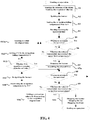
- FIG. 5 is a flowchart showing a processing procedure in which a conventional clothes dryer carries out a drying operation.
- the control unit generally is configured to perform a processing shown in FIG. 5 , and when a start button is pressed, the operation is started and proceeds to step T1.
- step T1 the control unit starts rotations of the drum and the fan. As a result, a supply and exhaust of the air for drying to and from the drum is started.
- step T2 the control unit ignites the burner. As a result, a supply of high-temperature air for drying to the drum is started.
- step T3 the control unit starts counting operation time.
- step T4 the control unit determines whether or not the operation time has reached the end time and determines whether or not to end the operation. When it is determined that the operation is to be terminated, the process proceeds to step T10, and when it is determined not to end the operation, the process proceeds to step T5.
- step T5 the control unit determines whether or not the exhaust temperature has reached an upper limit temperature. When it is determined that the exhaust temperature has reached the upper limit temperature, the process proceeds to step T6, and when it is not determined that the exhaust temperature has reached the upper limit temperature, the process returns to step T4.
- step T6 the control unit stops the burner. As a result, air for drying of a substantially normal temperature which is not heated is supplied into the drum, and the temperature inside the drum is lowered.
- step T7 the control unit determines whether or not the operation time has reached the end time, and determines whether or not to end the operation. When it is determined that the operation is to be ended, the process proceeds to step T10, and when it is determined not to end the operation, the process proceeds to step T8.
- step T8 the control unit determines whether or not the exhaust temperature has reached a re-ignition temperature. When it is determined that the re-ignition temperature has been reached, the process proceeds to step T9, and when it is determined that the re-ignition temperature has not been reached, the process returns to step T7.
- step T9 the control unit re-ignites the burner, and the process proceeds to step T4.
- step T4 the supply of high-temperature air for drying to the drum is resumed, and the temperature inside the drum rises again.
- step T10 the control unit stops the burner and stops the rotations of the fan and the drum, respectively. As a result, this flow is ended.
- a conventional clothes dryer suppresses an abnormal rise in the temperature inside the drum and the damage of the clothes due to overheating by repeating the following processes: when the exhaust temperature from the drum reaches the predetermined upper limit temperature, the burner (heat source) is stopped to lower the temperature inside the drum, and thereafter, when the exhaust temperature reaches the predetermined re-ignition temperature, the burner is re-ignited.
- such a control is considered as follows: the upper limit temperature is lowered in the latter half of the operation in which fire extinguishing and ignition of the burner are repeated, and the burner is stopped before the temperature inside the drum rises excessively.
- the clothes dryer cannot distinguish the type, weight, etc. of the clothes accommodated in the drum, due to the characteristics of the clothes dryer suitably used particularly for a laundromat, and it is difficult to determine at what point the latter half of the operation is. Therefore, it is difficult to adopt such a control.
- Patent Literature 1 Japanese Laid-Open Patent Publication No. 9-290095
- An object of the present invention is to effectively solve such a problem, and it is an object of the present invention to provide a clothes dryer capable of lowering the temperature in the latter half of the operation regardless of the type and the amount of clothes and sufficiently reducing damages to the clothes due to overheating and drying the entire clothes uniformly.
- the present invention adopts following technical solutions.
- a clothes dryer includes a drum capable of accommodating clothes, an air supply and exhaust unit for supplying and discharging air for drying to and from the drum, a heating unit for heating the air for drying supplied to the drum, an exhaust temperature detection unit for detecting the temperature of the air for drying that is discharged from drum, and a heating control unit for performing a temperature adjustment processing, the heating unit is stopped when an exhaust temperature detected by the exhaust temperature detection unit reaches a predetermined upper limit temperature, and it is re-operated when the exhaust temperature is lowered to a predetermined re-ignition temperature to perform a re-ignition.
- the heating control unit is provided with a re-ignition temperature adjustment part that performs an adjustment to lower the re-ignition temperature and the re-ignition temperature is gradually lowered through the re-ignition temperature adjustment part every time when the temperature adjustment processing is repeated intermittently to perform the re-ignition.
- the re-ignition temperature adjustment part lowers the re-ignition temperature in stages by a predetermined temperature to determine a new re-ignition temperature every time when the temperature adjustment processing is performed.
- the re-ignition temperature adjustment part pre-sets a lower limit value for the re-ignition temperature.
- the re-ignition temperature adjustment part keeps the re-ignition temperature at the lower limit value, and the heating control unit performs a re-ignition at the re-ignition temperature thereafter.
- the re-ignition temperature adjustment part acquires an elapsed time from the re-ignition until the exhaust temperature reaches a predetermined upper limit temperature, and adds a correction value to the predetermined temperature based on the elapsed time.
- the heating unit is a non-adjustable burner having no thermal power adjustment function.
- the air for drying heated by the heating unit is supplied into the drum by an air supply and exhaust unit to dry the clothes, and the point of time at which the exhaust temperature detected by the exhaust temperature detection unit exceeds the upper limit temperature is set to be a substantial boundary between the former half and the latter half of the drying operation.
- the point of time at which the exhaust temperature has reached the upper limit temperature is not taken as a reference point, but the point of time at which the exhaust temperature has dropped to the re-ignition temperature is taken as the reference point of the reheating operation of the heating unit. It is possible to perform the temperature adjustment processing by the heating control unit in the latter half of the drying operation without strictly estimating the type and the amount of the clothes to be dried.
- the heating control unit gradually reduces the re-ignition temperature down to the required temperature through the re-ignition temperature adjustment part, so that the unheated air for drying is used to dry the clothes, and the temperature inside the drum can be reliably lowered to a temperature lower than the temperature during the previous temperature adjustment processing. Consequently, regardless of the type and the amount of the clothes to be dried, the peak temperature in the drum for each temperature adjustment processing can be gradually reduced in the latter half of the drying operation to lower the temperature of the clothes in the overdrying condition, and it is possible to uniformly dry the whole clothes while sufficiently reducing the damage of clothes by overheating.
- a re-ignition temperature adjustment part gradually lowers the re-ignition temperature in stages by a predetermined temperature, it is possible to easily and gently control the above-described control in which the whole clothes can be dried uniformly while sufficiently reducing the damage of clothes by overheating.
- the re-ignition temperature adjustment part sets the lower limit value for the re-ignition temperature, it is possible to prevent the temperature of the clothes from dropping excessively in the latter half of the drying operation and ensure necessary drying performance without causing insufficient drying.
- the present invention in which a correction value is added to the re-ignition temperature in accordance with the elapsed time from the re-ignition to the stop of the heating, the presence or absence of the effect generated through the reduction in the re-ignition temperature is fed back, and a function of stably reducing temperature inside the drum is achieved.
- the manufacturing cost can be reduced compared with the case of using the adjustable burner.
- FIG. 1 is a schematic view showing a clothes dryer 1 according to an embodiment of the present invention.
- FIG.1 (A) is a front view of a clothes dryer 1
- FIG. 1(B) is a side view of a clothes dryer 1 according to an embodiment of the present invention.
- FIG. 2 is a block diagram showing structures of the clothes dryer 1.
- the clothes dryer 1 of the present embodiment includes a device main body 10, a drum 20 and a drum case 21, a drum motor 23, a burner 30, an air supply and exhaust unit 4, a temperature sensor (thermistor) 31, a control unit 5 (see FIG. 2 ), and is particularly suitably used in a laundromat.
- the interior of the device main body 10 is isolated by an upper partition plate 11 and a lower partition plate 12.
- a combustion chamber 13 is formed at the upper portion thereof, a drying chamber 14 is formed in the middle portion thereof, and a ventilation chamber 15 and a fan motor chamber 16 are formed at the lower portion thereof, respectively.
- the drum 20 is provided in the cylindrical drum case 21 in the drying chamber 14, and the drum 20 is arranged concentrically with the drum case 21 with its axis being the front-rear direction of the clothes dryer main body 1. Further, the drum 20 has a slightly smaller diameter than the drum case 21 and a large number of small holes (not shown) provided on its circumferential surface so that it can repeatedly rotate in the forward direction and the reverse direction to loosen the clothes. Such a drum 20 can accommodate the clothes L to be dried.
- An intake port 21a (see FIG. 1 (A) ) is formed at the upper left position of the drum case 21, and the intake port 21a communicates with a combustion chamber 13 to be described later via a short ventilation duct 17.
- An exhaust port 21b (see FIG. 1 (A) ) is formed at the lower right position of the drum case 21.
- the front side opening of the drum 20 can be tightly closed by the door 22 so as to freely open and close.
- the drum motor 23 is attached to the upper portion on the rear surface side of the device main body 10.
- the drum 20 is rotatably driven by the rotational force of the drum motor 23.
- the burner 30 is a non-adjustable type burner having no heating power adjusting function. Gas supply and gas interruption to the burner 30 are performed by the gas valve 30b shown in FIG. 2 .
- an igniter 30a (see FIG. 2 ) is provided in the vicinity of the burner 30.
- the air supply and exhaust unit 4 supplies and exhausts the air for drying to and from the drum 20, and has a supply and discharge passage 40, a discharge fan 48a, and a fan motor 48b.
- the supply and discharge passage 40 is constituted by the combustion chamber 13, the ventilation duct 17, the drum case 21, the ventilation port 40b formed in the lower partition plate 12 so as to face the exhaust port 21b, the ventilation chamber 15 and the fan motor chamber 16.
- the ventilation chamber 15 is formed below the lower partition plate 12 and is isolated from the fan motor chamber 16 by a partition plate 44 arranged substantially vertically. Further, an air filter 45 is disposed so as to straddle the lower end portion of the shielding plate 42 whose upper end portion is fixed to the lower partition plate 12 and the lower end portion of the partition plate 44, and a vent hole 44a is formed at the right position of the partition plate 44 (see FIG. 1 (A) ).
- an exhaust fan 48a on the front side of the fan partition plate 47 and a fan motor 48b on the rear side of the fan partition plate 47 for rotating the exhaust fan 48a are disposed.
- a ventilation opening 47a (see FIG. 1(A) ) is formed in the upper left portion of the fan partition plate 47.
- the temperature sensor 31 as the exhaust temperature detection unit, detects the temperature (exhaust temperature) of the air for drying discharged from the drum 20, and is disposed in the vicinity of the exhaust fan 48a, that is, the ventilation opening 47a of the fan partition plate 47. It is difficult to measure the temperature inside the drum 20 during operation in real time, but the temperature inside the drum 20 can be indirectly measured in real time by using the temperature sensor 31.
- the operation of such a clothes dryer 1 is controlled by a control unit 5 (see FIG. 2 ) including a microcomputer.
- the control unit 5 includes a heating control unit 55, a timer 51, a ROM 53, and a RAM 54.
- a program such as a temperature adjustment processing to be described later
- a pre-set operation is performed.
- data such as a re-ignition falling temperature N to be described later
- the control unit 5 is capable of outputting a fan motor drive signal to the fan motor 48b and can output a drum motor drive signal to the drum motor 23.
- the heating control unit 55 is capable of outputting an ignition signal to the igniter 30a and outputting a gas supply signal to the gas valve 30b.
- the heating control unit 55 performs the following temperature adjustment processing as follows: stopping the burner 30 when the exhaust temperature detected by the temperature sensor 31 reaches a predetermined upper limit temperature, and re-operating the burner 30 to perform a re-ignition when the exhaust temperature drops to a predetermined re-ignition temperature.
- the upper limit temperature is set to be about 70 °C
- the re-ignition temperature is set to be in a range of 40 to 45°C in advance.
- the heating control unit 55 has a re-ignition temperature adjustment part 56 for performing an adjustment to lower the re-ignition temperature.
- the re-ignition temperature is gradually lowered by the re-ignition temperature adjustment part 56 every time when the temperature adjustment processing is repeated intermittently to perform the re-ignition.
- a clothes dryer in the present embodiment includes: a drum 20 capable of accommodating clothes L, an air supply and exhaust unit 4 for supplying and discharging air for drying to and from the drum 20, a burner 30, as a heating unit, for heating the air for drying supplied to the drum 20, a temperature sensor 31, as an exhaust temperature detection unit, for detecting the temperature of the air for drying that is discharged from drum 20, and a heating control unit 55 for performing a temperature adjustment processing as follows: stopping the burner 30 when an exhaust temperature detected by the temperature sensor 31 reaches a predetermined upper limit temperature, and re-operating the burner 30 to perform a re-ignition when the exhaust temperature drops to a predetermined re-ignition temperature.
- the heating control unit 55 is provided with a re-ignition temperature adjustment part 56 that performs an adjustment to lower the re-ignition temperature, and the re-ignition temperature is gradually lowered through the re-ignition temperature adjustment part 56 every time when the temperature adjustment processing is repeated intermittently to perform the re-ignition.
- the air for drying heated by the burner 30 is supplied into the drum 20 by the air supply and exhaust unit 4 to dry the clothes L, and the point of time at which the exhaust temperature exceeds the upper limit temperature is set to be a substantial boundary between the former half and the latter half of the drying operation.
- the point of time at which the exhaust temperature has reached the upper limit temperature is not taken as the reference point, but the point of time at which the exhaust temperature has dropped to the re-ignition temperature is taken as the reference point of the reheating operation of the burner 30.
- the heating control unit 55 gradually reduces the re-ignition temperature down to the required temperature through the re-ignition temperature adjustment part 56, so that the unheated air for drying continues to dry the clothes L, and the temperature inside the drum 20 can be reliably lowered to a temperature lower than the temperature during the previous temperature adjustment processing. Consequently, regardless of the type and the amount of clothes L to be dried, the peak temperature in the drum 20 for every temperature adjustment processing can be gradually reduced in the latter half of the drying operation to stably lower the temperature of the clothes L in the overdrying condition, and it is possible to uniformly dry the whole clothes while sufficiently reducing the damage of the clothes L by overheating compared with the current method of keeping a continuous high-temperature operation.
- the number of times of ignition and extinction of the burner 30 is reduced as compared with the above-described method, which is advantageous also from the aspect of durability of the machine.
- the exhaust temperature reaches the upper limit temperature for the first time, the surface of the clothes L is in a substantially dried state, and the dried portions are more easily damaged by heat compared with the wetted portion.
- the temperature in the drum 20 is lowered by lowering the re-ignition temperature in a state where an undried portion possibly remains.
- FIG. 3 is a flowchart showing the processing procedure in the drying operation of the clothes dryer 1.
- the processing procedure of the drying operation will be specifically described with reference to FIG. 3 .
- the initial value of the re-ignition temperature is set to be 45°C.
- the subtraction value (a predetermined value) to decrease the re-ignition temperature step by step is set to be 1 °C.
- the cumulative value of the subtraction value is set to be the re-ignition fall temperature N
- the lower limit of the re-ignition value is set to be 40°C.
- step S1 the control unit 5 outputs a drum motor drive signal to the drum motor 23 to start the rotation of the drum 20, and outputs a fan motor drive signal to the fan motor 48b to start the rotation of the exhaust fan 48a.
- the air in the fan motor chamber 16 is discharged to the outside of the device, the air flows from the combustion chamber 13 toward the fan motor chamber 16 to flow to the supply and discharge passage 40, and supply and exhaust of the air for drying to and from the drum 20 is started.
- step S2 the heating control unit 55 outputs a gas supply signal to the gas valve 30b to turn on the gas valve 30b, and also outputs an ignition signal to the igniter 30a to ignite the burner 30. As a result, a supply of high-temperature air for drying to the drum 20 is started.
- step S3 the control unit 5 sets the initial value of the re-ignition falling temperature N to be 0 (°C).
- step S4 the control unit 5 causes the timer 51 to start counting the operation time.
- step S5 the control unit 5 determines whether or not the operation time has reached the end time based on the count value of the timer 51, and determines whether or not to end the operation.
- the process proceeds to step S14, and when it is not determined to end the operation, the process proceeds to step S6.
- step S6 the control unit 5 determines whether or not the exhaust temperature detected by the temperature sensor 31 has reached the upper limit temperature.
- the process proceeds to step S7, and when it is determined that the exhaust temperature has not reached the upper limit temperature, the process returns to step S5.
- step S7 the heating control unit 55 stops the supply of the gas to the burner 30 by the gas valve 30b and stops (extinguishes) the burner 30.
- step S8 based on the count value of the timer 51, the control unit 5 determines whether or not the operation time has reached the end time and determines whether or not to end the operation. When it is determined that the operation is to be terminated, the process proceeds to step S14, and when it is determined not to end the operation, the process proceeds to step S9.
- step S9 the control unit 5 determines whether or not the exhaust temperature detected by the temperature sensor 31 has decreased to the re-ignition temperature. When it is determined that the exhaust temperature has decreased to the re-ignition temperature, the process proceeds to step S10, and when it is determined that the exhaust temperature has not dropped to the re-ignition temperature, the process returns to step S8.
- step S10 the re-ignition temperature of the gas supply signal and the ignition signal is lowered by the re-ignition falling temperature N°C through the re-ignition temperature adjuster 56.
- step S11 the heating control unit 55 outputs a gas supply signal to the gas valve 30b and outputs an ignition signal to the igniter 30a to re-ignite the burner 30.
- step S12 the heating control unit 55 determines whether or not the re-ignition temperature has reached the lower limit value by determining whether or not the re-ignition falling temperature N has reached the set value (for example, 5°C).
- the process proceeds to step S5, and when it is determined that the re-ignition falling temperature N is not 5°C or higher, the process proceeds to step S13.
- the re-ignition temperature adjustment part 56 keeps the re-ignition temperature at the lower limit value (40°C) by keeping the re-ignition falling temperature N at a set value.
- the heating control unit 55 performs a subsequent temperature adjustment processing at the re-ignition temperature. For this reason, the temperature of the clothes is prevented from being excessively lowered, and the required drying performance is ensured without causing insufficient drying.
- the lower limit of the re-ignition temperature that is, the set value of the re-ignition falling temperature N, is not limited to 5°C as long as the effect of the present invention can be exerted.
- step S13 the control unit 5 adds 1°C to the re-ignition falling temperature N as a predetermined value.
- the re-ignition falling temperature N increases by 1°C at a time (each time the re-ignition temperature is lowered by 1°C) for each temperature adjustment processing until the re-ignition falling temperature N reaches the set value (for example, 5°C).
- the set value for example, 5°C.
- the predetermined value is generally set to be about 1°C, and thus, the peak temperature in the drum 20 for each temperature adjustment processing can be reduced in a manner of reducing damages to the clothes L and ensuring an appropriate temperature difference that can dry the undried portion in the latter half of the operation. Further, even if the upper limit arrival time point of the exhaust temperature deviates from the boundary between the former half and the latter half of the actual drying operation, since the re-ignition falling temperature N is added little by little, the peak temperature in the drum 20 for each temperature adjustment processing is gradually reduced so that it does not have a large influence on the drying performance.
- the predetermined value is not limited to 1 °C.
- step S14 the heating control unit 55 stops the burner 30, and the control unit 5 stops the rotations of the exhaust air fan 48a and the drum 20, respectively, thereby terminating the present flow.
- the clothes dryer 1 in the present embodiment has an operation course capable of reducing damages to the clothes by lowering the temperature of the clothes during overdrying of the clothes L.
- the upper limit temperature is set to be about 70 °C
- the re-ignition temperature is set to be at about 40 to 45°C
- the additional time A is set to be at 5 seconds.
- thermal power adjustment type burner capable of adjusting the thermal power in a plurality of stages and adjust the fire power of the burner to a small value after the exhaust temperature reaches the upper limit temperature, thereby lowering the temperature of the clothes.
- the manufacturing cost of the device rises.
- the temperature in the drum 20 is adjusted by updating the re-ignition falling temperature, and only the ON/OFF control is enough for the heating unit.
- the non-adjustable burner 30 is used as the heating unit, and it is particularly advantageous in terms of the manufacturing cost of device.
- the re-ignition temperature adjustment unit 56 is used to acquire the elapsed time T from the re-ignition until the exhaust temperature reaches the predetermined upper limit temperature, and it is effective that the correction value is added to the re-ignition falling temperature based on the elapsed time T.
- FIG. 4 is a flow chart corresponding to FIG. 3 showing the procedure. Common parts are denoted by the same reference numerals, and the explanations thereof are omitted. Next, the added steps are described below.
- step S13a counting is started for the elapsed time (the re-ignition elapsed time) since the re-ignition.
- step S7a the elapsed time for the exhaust temperature reaching the upper limit temperature is acquired.
- step S9a a correction value ⁇ is added to the re-ignition falling temperature N according to the elapsed time. That is, when the re-ignition falling temperature N is decreased, the elapsed time until the predetermined upper limit temperature is reached after the re-ignition is extended, but the elapsed time may hardly change depending on the amount of the laundry or the outside air temperature. Therefore, the re-ignition falling temperature N will be corrected to N+ ⁇ . If both N and ⁇ are 1 °C, the re-ignition temperature will be lowered by 2 °C in steps S9a and S10. Whether or not the elapsed time has changed is determined depending on whether or not it has been changed into a threshold value (for example, 5 seconds). Conversely, in the case where the elapsed time is greatly extended even by lowering by 1 °C in step S10, ⁇ may be configured to take a negative value depending on the situation.
- a threshold value for example, 5 seconds
- the burner 30 is used as the heating unit, but other burners may also be used as long as the drying air can be heated.
- the re-ignition temperature in the subsequent temperature adjustment processing is determined by adding a predetermined value to the re-ignition falling temperature N.
- a new re-ignition temperature may be determined based on a table in which the number of repetitions of the temperature adjustment processing and the re-ignition temperature are associated with each other.
Landscapes
- Engineering & Computer Science (AREA)
- Textile Engineering (AREA)
- Control Of Washing Machine And Dryer (AREA)
- Detail Structures Of Washing Machines And Dryers (AREA)
- Drying Of Solid Materials (AREA)
Abstract
Description
- The present invention relates to a clothes dryer capable of reducing damages to clothes by lowering a temperature of the clothes during overdrying regardless of the type and the amount of the clothes.
- Conventionally, a clothes dryer is known in which air for drying heated by a burner is blown into a drum into which clothes to be dried is introduced by a fan, and an exhaust is performed from a back side of a main body (see, for example, Patent Document 1).
-
FIG. 5 is a flowchart showing a processing procedure in which a conventional clothes dryer carries out a drying operation. Regarding the clothes dryer disclosed in Patent Document 1, the control unit generally is configured to perform a processing shown inFIG. 5 , and when a start button is pressed, the operation is started and proceeds to step T1. - In step T1, the control unit starts rotations of the drum and the fan. As a result, a supply and exhaust of the air for drying to and from the drum is started.
- In step T2, the control unit ignites the burner. As a result, a supply of high-temperature air for drying to the drum is started.
- In step T3, the control unit starts counting operation time.
- In step T4, the control unit determines whether or not the operation time has reached the end time and determines whether or not to end the operation. When it is determined that the operation is to be terminated, the process proceeds to step T10, and when it is determined not to end the operation, the process proceeds to step T5.
- In step T5, the control unit determines whether or not the exhaust temperature has reached an upper limit temperature. When it is determined that the exhaust temperature has reached the upper limit temperature, the process proceeds to step T6, and when it is not determined that the exhaust temperature has reached the upper limit temperature, the process returns to step T4.
- In step T6, the control unit stops the burner. As a result, air for drying of a substantially normal temperature which is not heated is supplied into the drum, and the temperature inside the drum is lowered.
- In step T7, the control unit determines whether or not the operation time has reached the end time, and determines whether or not to end the operation. When it is determined that the operation is to be ended, the process proceeds to step T10, and when it is determined not to end the operation, the process proceeds to step T8.
- In step T8, the control unit determines whether or not the exhaust temperature has reached a re-ignition temperature. When it is determined that the re-ignition temperature has been reached, the process proceeds to step T9, and when it is determined that the re-ignition temperature has not been reached, the process returns to step T7.
- In step T9, the control unit re-ignites the burner, and the process proceeds to step T4. As a result, the supply of high-temperature air for drying to the drum is resumed, and the temperature inside the drum rises again.
- In step T10, the control unit stops the burner and stops the rotations of the fan and the drum, respectively. As a result, this flow is ended.
- As described above, a conventional clothes dryer suppresses an abnormal rise in the temperature inside the drum and the damage of the clothes due to overheating by repeating the following processes: when the exhaust temperature from the drum reaches the predetermined upper limit temperature, the burner (heat source) is stopped to lower the temperature inside the drum, and thereafter, when the exhaust temperature reaches the predetermined re-ignition temperature, the burner is re-ignited.
- However, in the above-described drying operation, even after the exhaust temperature reaches the upper limit temperature, that is, moisture contained in the clothes decreases, at least a portion of the clothes have almost been dried and become excessively dried, and when the exhaust temperature reaches the re-ignition temperature, the burner is re-ignited at once so that the temperature inside the drum is kept high and the surface temperature of the clothes keeps rising all the time. Such a state leads to a bruise of clothes, and the clothes dryer performing the conventional drying operation has room for improvement concerning a reduction of the damages of the clothes caused by overheating.
- To solve this problem, such a control is considered as follows: the upper limit temperature is lowered in the latter half of the operation in which fire extinguishing and ignition of the burner are repeated, and the burner is stopped before the temperature inside the drum rises excessively. However, the clothes dryer cannot distinguish the type, weight, etc. of the clothes accommodated in the drum, due to the characteristics of the clothes dryer suitably used particularly for a laundromat, and it is difficult to determine at what point the latter half of the operation is. Therefore, it is difficult to adopt such a control.
- Patent Literature 1: Japanese Laid-Open Patent Publication No.
9-290095 - An object of the present invention is to effectively solve such a problem, and it is an object of the present invention to provide a clothes dryer capable of lowering the temperature in the latter half of the operation regardless of the type and the amount of clothes and sufficiently reducing damages to the clothes due to overheating and drying the entire clothes uniformly.
- In view of the above problems, the present invention adopts following technical solutions.
- That is, a clothes dryer according to the present invention includes a drum capable of accommodating clothes, an air supply and exhaust unit for supplying and discharging air for drying to and from the drum, a heating unit for heating the air for drying supplied to the drum, an exhaust temperature detection unit for detecting the temperature of the air for drying that is discharged from drum, and a heating control unit for performing a temperature adjustment processing, the heating unit is stopped when an exhaust temperature detected by the exhaust temperature detection unit reaches a predetermined upper limit temperature, and it is re-operated when the exhaust temperature is lowered to a predetermined re-ignition temperature to perform a re-ignition. The heating control unit is provided with a re-ignition temperature adjustment part that performs an adjustment to lower the re-ignition temperature and the re-ignition temperature is gradually lowered through the re-ignition temperature adjustment part every time when the temperature adjustment processing is repeated intermittently to perform the re-ignition.
- In particular, it is preferable that the re-ignition temperature adjustment part lowers the re-ignition temperature in stages by a predetermined temperature to determine a new re-ignition temperature every time when the temperature adjustment processing is performed.
- Furthermore, the re-ignition temperature adjustment part pre-sets a lower limit value for the re-ignition temperature. When the temperature adjustment processing is repeated to enable the re-ignition temperature to reach the lower limit value, the re-ignition temperature adjustment part keeps the re-ignition temperature at the lower limit value, and the heating control unit performs a re-ignition at the re-ignition temperature thereafter.
- In these cases, it is also preferable that the re-ignition temperature adjustment part acquires an elapsed time from the re-ignition until the exhaust temperature reaches a predetermined upper limit temperature, and adds a correction value to the predetermined temperature based on the elapsed time.
- In addition, it is preferable that the heating unit is a non-adjustable burner having no thermal power adjustment function.
- According to the present invention described above, the air for drying heated by the heating unit is supplied into the drum by an air supply and exhaust unit to dry the clothes, and the point of time at which the exhaust temperature detected by the exhaust temperature detection unit exceeds the upper limit temperature is set to be a substantial boundary between the former half and the latter half of the drying operation. The point of time at which the exhaust temperature has reached the upper limit temperature is not taken as a reference point, but the point of time at which the exhaust temperature has dropped to the re-ignition temperature is taken as the reference point of the reheating operation of the heating unit. It is possible to perform the temperature adjustment processing by the heating control unit in the latter half of the drying operation without strictly estimating the type and the amount of the clothes to be dried. Every time this temperature adjustment processing is repeated intermittently, the heating control unit gradually reduces the re-ignition temperature down to the required temperature through the re-ignition temperature adjustment part, so that the unheated air for drying is used to dry the clothes, and the temperature inside the drum can be reliably lowered to a temperature lower than the temperature during the previous temperature adjustment processing. Consequently, regardless of the type and the amount of the clothes to be dried, the peak temperature in the drum for each temperature adjustment processing can be gradually reduced in the latter half of the drying operation to lower the temperature of the clothes in the overdrying condition, and it is possible to uniformly dry the whole clothes while sufficiently reducing the damage of clothes by overheating.
- Particularly, according to the present invention in which a re-ignition temperature adjustment part gradually lowers the re-ignition temperature in stages by a predetermined temperature, it is possible to easily and gently control the above-described control in which the whole clothes can be dried uniformly while sufficiently reducing the damage of clothes by overheating.
- Furthermore, according to the present invention in which the re-ignition temperature adjustment part sets the lower limit value for the re-ignition temperature, it is possible to prevent the temperature of the clothes from dropping excessively in the latter half of the drying operation and ensure necessary drying performance without causing insufficient drying.
- Furthermore, according to the present invention in which a correction value is added to the re-ignition temperature in accordance with the elapsed time from the re-ignition to the stop of the heating, the presence or absence of the effect generated through the reduction in the re-ignition temperature is fed back, and a function of stably reducing temperature inside the drum is achieved.
- In addition, according to the present invention in which the heating unit is a non-adjustable burner, the manufacturing cost can be reduced compared with the case of using the adjustable burner.
-
-
FIG. 1 is a schematic view showing a clothes dryer according to an embodiment of the present invention; -
FIG. 2 is a block diagram showing structures of the same clothes dryer; -
FIG. 3 is a flowchart showing a processing procedure of a drying operation of the same clothes dryer; -
FIG. 4 is a flowchart ofFIG. 3 corresponding to a modified example of the present invention; and -
FIG. 5 is a flowchart showing a processing procedure in a drying operation of a conventional clothes dryer. - Hereinafter, an embodiment of the present invention will be described with reference to the drawings.
-
FIG. 1 is a schematic view showing a clothes dryer 1 according to an embodiment of the present invention.FIG.1 (A) is a front view of a clothes dryer 1, andFIG. 1(B) is a side view of a clothes dryer 1 according to an embodiment of the present invention.FIG. 2 is a block diagram showing structures of the clothes dryer 1. - The clothes dryer 1 of the present embodiment includes a device
main body 10, adrum 20 and adrum case 21, adrum motor 23, aburner 30, an air supply andexhaust unit 4, a temperature sensor (thermistor) 31, a control unit 5 (seeFIG. 2 ), and is particularly suitably used in a laundromat. - The interior of the device
main body 10 is isolated by anupper partition plate 11 and alower partition plate 12. Acombustion chamber 13 is formed at the upper portion thereof, a dryingchamber 14 is formed in the middle portion thereof, and aventilation chamber 15 and afan motor chamber 16 are formed at the lower portion thereof, respectively. - The
drum 20 is provided in thecylindrical drum case 21 in the dryingchamber 14, and thedrum 20 is arranged concentrically with thedrum case 21 with its axis being the front-rear direction of the clothes dryer main body 1. Further, thedrum 20 has a slightly smaller diameter than thedrum case 21 and a large number of small holes (not shown) provided on its circumferential surface so that it can repeatedly rotate in the forward direction and the reverse direction to loosen the clothes. Such adrum 20 can accommodate the clothes L to be dried. - An
intake port 21a (seeFIG. 1 (A) ) is formed at the upper left position of thedrum case 21, and theintake port 21a communicates with acombustion chamber 13 to be described later via ashort ventilation duct 17. Anexhaust port 21b (seeFIG. 1 (A) ) is formed at the lower right position of thedrum case 21. The front side opening of thedrum 20 can be tightly closed by thedoor 22 so as to freely open and close. - The
drum motor 23 is attached to the upper portion on the rear surface side of the devicemain body 10. Thedrum 20 is rotatably driven by the rotational force of thedrum motor 23. - A
burner 30, as a heating unit, is provided in thecombustion chamber 13 and heats the air for drying supplied into thedrum 20 through the small holes. In addition, theburner 30 is a non-adjustable type burner having no heating power adjusting function. Gas supply and gas interruption to theburner 30 are performed by thegas valve 30b shown inFIG. 2 . Besides, anigniter 30a (seeFIG. 2 ) is provided in the vicinity of theburner 30. - The air supply and
exhaust unit 4 supplies and exhausts the air for drying to and from thedrum 20, and has a supply anddischarge passage 40, adischarge fan 48a, and afan motor 48b. - The supply and
discharge passage 40 is constituted by thecombustion chamber 13, theventilation duct 17, thedrum case 21, theventilation port 40b formed in thelower partition plate 12 so as to face theexhaust port 21b, theventilation chamber 15 and thefan motor chamber 16. - The
ventilation chamber 15 is formed below thelower partition plate 12 and is isolated from thefan motor chamber 16 by apartition plate 44 arranged substantially vertically. Further, anair filter 45 is disposed so as to straddle the lower end portion of the shieldingplate 42 whose upper end portion is fixed to thelower partition plate 12 and the lower end portion of thepartition plate 44, and avent hole 44a is formed at the right position of the partition plate 44 (seeFIG. 1 (A) ). - In the
fan motor chamber 16, anexhaust fan 48a on the front side of thefan partition plate 47 and afan motor 48b on the rear side of thefan partition plate 47 for rotating theexhaust fan 48a are disposed. Aventilation opening 47a (seeFIG. 1(A) ) is formed in the upper left portion of thefan partition plate 47. - The
temperature sensor 31, as the exhaust temperature detection unit, detects the temperature (exhaust temperature) of the air for drying discharged from thedrum 20, and is disposed in the vicinity of theexhaust fan 48a, that is, theventilation opening 47a of thefan partition plate 47. It is difficult to measure the temperature inside thedrum 20 during operation in real time, but the temperature inside thedrum 20 can be indirectly measured in real time by using thetemperature sensor 31. - The operation of such a clothes dryer 1 is controlled by a control unit 5 (see
FIG. 2 ) including a microcomputer. Thecontrol unit 5 includes aheating control unit 55, atimer 51, aROM 53, and aRAM 54. By executing a program (such as a temperature adjustment processing to be described later) stored in theROM 53 by a microcomputer, a pre-set operation is performed. In theRAM 54, data (such as a re-ignition falling temperature N to be described later) to be used for executing the above program is temporarily stored. - The
control unit 5 is capable of outputting a fan motor drive signal to thefan motor 48b and can output a drum motor drive signal to thedrum motor 23. - The
heating control unit 55 is capable of outputting an ignition signal to theigniter 30a and outputting a gas supply signal to thegas valve 30b. - The
heating control unit 55 performs the following temperature adjustment processing as follows: stopping theburner 30 when the exhaust temperature detected by thetemperature sensor 31 reaches a predetermined upper limit temperature, and re-operating theburner 30 to perform a re-ignition when the exhaust temperature drops to a predetermined re-ignition temperature. In the present embodiment, for example, the upper limit temperature is set to be about 70 °C, and the re-ignition temperature is set to be in a range of 40 to 45°C in advance. - Furthermore, the
heating control unit 55 has a re-ignitiontemperature adjustment part 56 for performing an adjustment to lower the re-ignition temperature. The re-ignition temperature is gradually lowered by the re-ignitiontemperature adjustment part 56 every time when the temperature adjustment processing is repeated intermittently to perform the re-ignition. - As described above, a clothes dryer in the present embodiment includes: a
drum 20 capable of accommodating clothes L, an air supply andexhaust unit 4 for supplying and discharging air for drying to and from thedrum 20, aburner 30, as a heating unit, for heating the air for drying supplied to thedrum 20, atemperature sensor 31, as an exhaust temperature detection unit, for detecting the temperature of the air for drying that is discharged fromdrum 20, and aheating control unit 55 for performing a temperature adjustment processing as follows: stopping theburner 30 when an exhaust temperature detected by thetemperature sensor 31 reaches a predetermined upper limit temperature, and re-operating theburner 30 to perform a re-ignition when the exhaust temperature drops to a predetermined re-ignition temperature. Theheating control unit 55 is provided with a re-ignitiontemperature adjustment part 56 that performs an adjustment to lower the re-ignition temperature, and the re-ignition temperature is gradually lowered through the re-ignitiontemperature adjustment part 56 every time when the temperature adjustment processing is repeated intermittently to perform the re-ignition. - With such a configuration, the air for drying heated by the
burner 30 is supplied into thedrum 20 by the air supply andexhaust unit 4 to dry the clothes L, and the point of time at which the exhaust temperature exceeds the upper limit temperature is set to be a substantial boundary between the former half and the latter half of the drying operation. The point of time at which the exhaust temperature has reached the upper limit temperature is not taken as the reference point, but the point of time at which the exhaust temperature has dropped to the re-ignition temperature is taken as the reference point of the reheating operation of theburner 30. Thus, it is possible to perform the temperature adjustment processing by theheating control unit 55 in the latter half of the drying operation without strictly estimating the kind and the amount of the clothes L to be dried inside thedrum 20. Every time this temperature adjustment processing is repeated intermittently, theheating control unit 55 gradually reduces the re-ignition temperature down to the required temperature through the re-ignitiontemperature adjustment part 56, so that the unheated air for drying continues to dry the clothes L, and the temperature inside thedrum 20 can be reliably lowered to a temperature lower than the temperature during the previous temperature adjustment processing. Consequently, regardless of the type and the amount of clothes L to be dried, the peak temperature in thedrum 20 for every temperature adjustment processing can be gradually reduced in the latter half of the drying operation to stably lower the temperature of the clothes L in the overdrying condition, and it is possible to uniformly dry the whole clothes while sufficiently reducing the damage of the clothes L by overheating compared with the current method of keeping a continuous high-temperature operation. - Furthermore, in making such an effect, new sensors are unnecessary, and the conventional mechanic configuration can be adopted without costs.
- It should be noted that, as another method for lowering the temperature of the clothes with a boundary as the upper limit temperature is reached, it is conceivable to lower the upper limit temperature itself from the time when the exhaust temperature reaches the upper limit temperature. However, since this method is carried out after the
burner 30 is re-ignited, the time for the exhaust temperature to reach the upper limit temperature again is advanced. Thus, the number of times of ignition and extinction of theburner 30 increases throughout the operation, which is disadvantageous in terms of the durability of the machine. - In the present invention, the number of times of ignition and extinction of the
burner 30 is reduced as compared with the above-described method, which is advantageous also from the aspect of durability of the machine. - Also, as described above, when the exhaust temperature reaches the upper limit temperature for the first time, the surface of the clothes L is in a substantially dried state, and the dried portions are more easily damaged by heat compared with the wetted portion. This point is not noted in the prior art, and the following idea is also not mentioned: the temperature in the
drum 20 is lowered by lowering the re-ignition temperature in a state where an undried portion possibly remains. -
FIG. 3 is a flowchart showing the processing procedure in the drying operation of the clothes dryer 1. Hereinafter, the processing procedure of the drying operation will be specifically described with reference toFIG. 3 . In this case, the initial value of the re-ignition temperature is set to be 45°C., the subtraction value (a predetermined value) to decrease the re-ignition temperature step by step is set to be 1 °C., the cumulative value of the subtraction value is set to be the re-ignition fall temperature N, and the lower limit of the re-ignition value is set to be 40°C. - When the clothes L to be dried is thrown into the
drum 20 by opening thedoor 22, and thedoor 22 is closed and a start button (not shown) is pushed, this flow starts. - In step S1, the
control unit 5 outputs a drum motor drive signal to thedrum motor 23 to start the rotation of thedrum 20, and outputs a fan motor drive signal to thefan motor 48b to start the rotation of theexhaust fan 48a. As a result, the air in thefan motor chamber 16 is discharged to the outside of the device, the air flows from thecombustion chamber 13 toward thefan motor chamber 16 to flow to the supply anddischarge passage 40, and supply and exhaust of the air for drying to and from thedrum 20 is started. - In step S2, the
heating control unit 55 outputs a gas supply signal to thegas valve 30b to turn on thegas valve 30b, and also outputs an ignition signal to theigniter 30a to ignite theburner 30. As a result, a supply of high-temperature air for drying to thedrum 20 is started. - In step S3, the
control unit 5 sets the initial value of the re-ignition falling temperature N to be 0 (°C). - In step S4, the
control unit 5 causes thetimer 51 to start counting the operation time. - In step S5, the
control unit 5 determines whether or not the operation time has reached the end time based on the count value of thetimer 51, and determines whether or not to end the operation. When it is determined that the operation is to be terminated, the process proceeds to step S14, and when it is not determined to end the operation, the process proceeds to step S6. - In step S6, the
control unit 5 determines whether or not the exhaust temperature detected by thetemperature sensor 31 has reached the upper limit temperature. When it is determined that the exhaust temperature has reached the upper limit temperature, the process proceeds to step S7, and when it is determined that the exhaust temperature has not reached the upper limit temperature, the process returns to step S5. It should be noted that, when the amount of moisture in thedrum 20 is large, even if the high-temperature air for drying is supplied, the amount of heat is utilized for the evaporation of water, and the temperature inside thedrum 20 is hard to rise. The more the amount of clothes and the amount of moisture contained in the clothes are, the more time it takes for the exhaust temperature to reach the upper limit temperature. The time depends on the fabric and the amount of the clothes L and the like. However, when the exhaust temperature reaches the upper limit temperature for the first time, even if the surface of the clothes L is dried, the interior still is in a wet state. - In step S7, the
heating control unit 55 stops the supply of the gas to theburner 30 by thegas valve 30b and stops (extinguishes) theburner 30. - In step S8, based on the count value of the
timer 51, thecontrol unit 5 determines whether or not the operation time has reached the end time and determines whether or not to end the operation. When it is determined that the operation is to be terminated, the process proceeds to step S14, and when it is determined not to end the operation, the process proceeds to step S9. - In step S9, the
control unit 5 determines whether or not the exhaust temperature detected by thetemperature sensor 31 has decreased to the re-ignition temperature. When it is determined that the exhaust temperature has decreased to the re-ignition temperature, the process proceeds to step S10, and when it is determined that the exhaust temperature has not dropped to the re-ignition temperature, the process returns to step S8. - In step S10, the re-ignition temperature of the gas supply signal and the ignition signal is lowered by the re-ignition falling temperature N°C through the
re-ignition temperature adjuster 56. - In step S11, the
heating control unit 55 outputs a gas supply signal to thegas valve 30b and outputs an ignition signal to theigniter 30a to re-ignite theburner 30. - In step S12, the
heating control unit 55 determines whether or not the re-ignition temperature has reached the lower limit value by determining whether or not the re-ignition falling temperature N has reached the set value (for example, 5°C). When it is determined that the re-ignition falling temperature N is equal to or higher than 5°C, the process proceeds to step S5, and when it is determined that the re-ignition falling temperature N is not 5°C or higher, the process proceeds to step S13. - That is, when the re-ignition temperature reaches the lower limit value, the re-ignition
temperature adjustment part 56 keeps the re-ignition temperature at the lower limit value (40°C) by keeping the re-ignition falling temperature N at a set value. Theheating control unit 55 performs a subsequent temperature adjustment processing at the re-ignition temperature. For this reason, the temperature of the clothes is prevented from being excessively lowered, and the required drying performance is ensured without causing insufficient drying. It should be noted that, the lower limit of the re-ignition temperature, that is, the set value of the re-ignition falling temperature N, is not limited to 5°C as long as the effect of the present invention can be exerted. - In step S13, the
control unit 5 adds 1°C to the re-ignition falling temperature N as a predetermined value. As a result, the re-ignition falling temperature N increases by 1°C at a time (each time the re-ignition temperature is lowered by 1°C) for each temperature adjustment processing until the re-ignition falling temperature N reaches the set value (for example, 5°C). As described above, with respect to the initial value of the re-ignition temperature, each time the temperature adjustment processing is performed, the re-ignition falling temperature N is added incrementally, and thus, the re-ignition temperature is lowered stage by stage to perform a re-ignition. Therefore, it is possible to easily realize the above-described control capable of uniformly drying the entire clothes L while sufficiently reducing the damage to the clothes L by overheating. Further, the predetermined value is generally set to be about 1°C, and thus, the peak temperature in thedrum 20 for each temperature adjustment processing can be reduced in a manner of reducing damages to the clothes L and ensuring an appropriate temperature difference that can dry the undried portion in the latter half of the operation. Further, even if the upper limit arrival time point of the exhaust temperature deviates from the boundary between the former half and the latter half of the actual drying operation, since the re-ignition falling temperature N is added little by little, the peak temperature in thedrum 20 for each temperature adjustment processing is gradually reduced so that it does not have a large influence on the drying performance. Of course, the predetermined value is not limited to 1 °C. - In step S14, the
heating control unit 55 stops theburner 30, and thecontrol unit 5 stops the rotations of theexhaust air fan 48a and thedrum 20, respectively, thereby terminating the present flow. - As described above, the clothes dryer 1 in the present embodiment has an operation course capable of reducing damages to the clothes by lowering the temperature of the clothes during overdrying of the clothes L. It should be noted that, regarding the clothes dryer 1 in an experiment, the upper limit temperature is set to be about 70 °C, the re-ignition temperature is set to be at about 40 to 45°C, and the additional time A is set to be at 5 seconds. When the above experiment is compared with the case shown in
Fig. 5 , which indicates the current drying operation, the peak temperature in thedrum 20 during the drying operation could be reduced by about 10°C. The experimental values are obtained from the Thermo Label (registered trademark) capable of measuring the highest temperature in thedrum 20. - It should be noted that, as another method of lowering the clothes temperature during overdrying, it is considered to use a thermal power adjustment type burner capable of adjusting the thermal power in a plurality of stages and adjust the fire power of the burner to a small value after the exhaust temperature reaches the upper limit temperature, thereby lowering the temperature of the clothes.
- In this case, it is considered possible that the number of times of ignition and extinguishment is suppressed after the fire power of the burner is adjusted and that there are few problems in terms of durability of the machine. However, when an adjustable burner is used, the manufacturing cost of the device rises. In the present invention, the temperature in the
drum 20 is adjusted by updating the re-ignition falling temperature, and only the ON/OFF control is enough for the heating unit. Thus, it is possible to use thenon-adjustable burner 30 as the heating unit, and it is particularly advantageous in terms of the manufacturing cost of device. - Although one embodiment of the present invention has been described above, the specific configuration of each part is not limited to the above-described embodiment.
- For example, the re-ignition
temperature adjustment unit 56 is used to acquire the elapsed time T from the re-ignition until the exhaust temperature reaches the predetermined upper limit temperature, and it is effective that the correction value is added to the re-ignition falling temperature based on the elapsed time T. -
FIG. 4 is a flow chart corresponding toFIG. 3 showing the procedure. Common parts are denoted by the same reference numerals, and the explanations thereof are omitted. Next, the added steps are described below. - In step S13a, counting is started for the elapsed time (the re-ignition elapsed time) since the re-ignition.
- In step S7a, the elapsed time for the exhaust temperature reaching the upper limit temperature is acquired.
- In step S9a, a correction value α is added to the re-ignition falling temperature N according to the elapsed time. That is, when the re-ignition falling temperature N is decreased, the elapsed time until the predetermined upper limit temperature is reached after the re-ignition is extended, but the elapsed time may hardly change depending on the amount of the laundry or the outside air temperature. Therefore, the re-ignition falling temperature N will be corrected to N+α. If both N and α are 1 °C, the re-ignition temperature will be lowered by 2 °C in steps S9a and S10. Whether or not the elapsed time has changed is determined depending on whether or not it has been changed into a threshold value (for example, 5 seconds). Conversely, in the case where the elapsed time is greatly extended even by lowering by 1 °C in step S10, α may be configured to take a negative value depending on the situation.
- By doing so, it is possible to provide a feedback on whether the effect is good or bad by lowering the re-ignition falling temperature, and more accurately, the temperature is stably reduced in the drum.
- In the present embodiment, the
burner 30 is used as the heating unit, but other burners may also be used as long as the drying air can be heated. - Furthermore, in the above-described embodiment, the re-ignition temperature in the subsequent temperature adjustment processing is determined by adding a predetermined value to the re-ignition falling temperature N. However, it is not limited to this, and the next re-ignition temperature can be determined by setting the re-ignition temperature to be a predetermined variable with t=0 as an initial value or by multiplying the re-ignition temperature by a predetermined coefficient. In addition, a new re-ignition temperature may be determined based on a table in which the number of repetitions of the temperature adjustment processing and the re-ignition temperature are associated with each other.
- Various modifications are possible in other configurations without departing from the technical spirits of the present invention.
- 1: Clothes dryer; 4: Air supply and exhaust unit; 20: Drum; 30: Burner (heating unit); 31: Temperature sensor (exhaust temperature detection unit); 55: Heating control unit; 56: Re-ignition temperature adjustment portion; L: Clothes; N: Re-ignition falling temperature.
Claims (5)
- A clothes dryer, comprising:a drum capable of accommodating clothes,an air supply and exhaust unit for supplying and discharging air for drying to and from the drum,a heating unit for heating the air for drying supplied to the drum,an exhaust temperature detection unit for detecting the temperature of the air for drying that is discharged from the drum, anda heating control unit for performing a temperature adjustment processing as follows: stopping the heating unit when an exhaust temperature detected by the exhaust temperature detection unit reaches a predetermined upper limit temperature, and re-operating the heating unit to perform a re-ignition when the exhaust temperature drops to a predetermined re-ignition temperature, whereinthe heating control unit is provided with a re-ignition temperature adjustment part that performs an adjustment to lower the re-ignition temperature, and the re-ignition temperature is gradually lowered through the re-ignition temperature adjustment part every time when the temperature adjustment processing is repeated intermittently to perform the re-ignition.
- The clothes dryer according to claim 1, wherein the re-ignition temperature adjustment part lowers the re-ignition temperature in stages by a predetermined temperature to determine a new re-ignition temperature every time when the temperature adjustment processing is performed.
- The clothes dryer according to claim 2, wherein the re-ignition temperature adjustment part pre-sets a lower limit value for the re-ignition temperature, and when the temperature adjustment processing is repeated to enable the re-ignition temperature to reach the lower limit value, the re-ignition temperature adjustment part keeps the re-ignition temperature at the lower limit value, and the heating control unit performs the re-ignition at the re-ignition temperature thereafter.
- The clothes dryer according to claim 2 or claim 3, wherein the re-ignition temperature adjustment part acquires an elapsed time from the re-ignition until the exhaust temperature reaches a predetermined upper limit temperature, and adds a correction value to the predetermined temperature based on the elapsed time.
- The clothes dryer according to any one of claims 1 to 4, wherein the heating unit is a non-adjustable burner having no thermal power adjustment function.
Applications Claiming Priority (2)
| Application Number | Priority Date | Filing Date | Title |
|---|---|---|---|
| JP2015244788A JP6683469B2 (en) | 2015-12-16 | 2015-12-16 | Clothes dryer |
| PCT/CN2016/110375 WO2017101855A1 (en) | 2015-12-16 | 2016-12-16 | Dryer |
Publications (3)
| Publication Number | Publication Date |
|---|---|
| EP3392399A1 true EP3392399A1 (en) | 2018-10-24 |
| EP3392399A4 EP3392399A4 (en) | 2019-07-10 |
| EP3392399B1 EP3392399B1 (en) | 2020-08-05 |
Family
ID=59055719
Family Applications (1)
| Application Number | Title | Priority Date | Filing Date |
|---|---|---|---|
| EP16874912.5A Active EP3392399B1 (en) | 2015-12-16 | 2016-12-16 | Clothes dryer |
Country Status (5)
| Country | Link |
|---|---|
| US (1) | US20180371683A1 (en) |
| EP (1) | EP3392399B1 (en) |
| JP (1) | JP6683469B2 (en) |
| CN (1) | CN108368668B (en) |
| WO (1) | WO2017101855A1 (en) |
Families Citing this family (3)
| Publication number | Priority date | Publication date | Assignee | Title |
|---|---|---|---|---|
| JP6890068B2 (en) * | 2017-08-25 | 2021-06-18 | リンナイ株式会社 | Clothes dryer |
| JP7018290B2 (en) | 2017-10-24 | 2022-02-10 | リンナイ株式会社 | Clothes dryer |
| CN112522929B (en) * | 2019-09-17 | 2024-07-23 | 青岛胶州海尔洗涤电器有限公司 | A method for cleaning wire scraps at electric heating wire of clothes dryer and clothes dryer |
Family Cites Families (10)
| Publication number | Priority date | Publication date | Assignee | Title |
|---|---|---|---|---|
| US4991313A (en) * | 1990-01-22 | 1991-02-12 | White Consolidated Industries, Inc. | Gradual heat reduction for a clothes dryer |
| US5161314A (en) * | 1991-06-17 | 1992-11-10 | American Dryer Corporation | Apparatus and method for controlling a drying cool-down cycle of a clothes dryer |
| JP3098659B2 (en) * | 1993-06-29 | 2000-10-16 | 東京瓦斯株式会社 | Operation control device for gas clothing dryer |
| JPH09290095A (en) * | 1996-04-26 | 1997-11-11 | Sanyo Electric Co Ltd | Gas clothes dryer |
| US6079121A (en) * | 1998-08-03 | 2000-06-27 | Ther-O-Disc, Incorporated | Humidity-modulated dual-setpoint temperature controller |
| CN2479048Y (en) * | 2001-02-23 | 2002-02-27 | 广东万家乐燃气具有限公司 | Full-automatic laundry drier |
| CN100375817C (en) * | 2002-12-25 | 2008-03-19 | 乐金电子(天津)电器有限公司 | Heater controller of drier |
| US6715216B1 (en) * | 2003-07-11 | 2004-04-06 | Cissell Manufacturing Company | Clothes dryer with fire suppression system |
| KR100811487B1 (en) * | 2007-02-13 | 2008-03-07 | 엘지전자 주식회사 | Ductless dryer |
| KR20140065263A (en) * | 2012-11-21 | 2014-05-29 | 엘지전자 주식회사 | Clothes treating apparatus with hot air supply device and an operating method thereof |
-
2015
- 2015-12-16 JP JP2015244788A patent/JP6683469B2/en active Active
-
2016
- 2016-12-16 US US16/063,210 patent/US20180371683A1/en not_active Abandoned
- 2016-12-16 WO PCT/CN2016/110375 patent/WO2017101855A1/en not_active Ceased
- 2016-12-16 CN CN201680073226.1A patent/CN108368668B/en active Active
- 2016-12-16 EP EP16874912.5A patent/EP3392399B1/en active Active
Also Published As
| Publication number | Publication date |
|---|---|
| US20180371683A1 (en) | 2018-12-27 |
| CN108368668A (en) | 2018-08-03 |
| EP3392399B1 (en) | 2020-08-05 |
| JP2017108870A (en) | 2017-06-22 |
| JP6683469B2 (en) | 2020-04-22 |
| CN108368668B (en) | 2020-09-08 |
| EP3392399A4 (en) | 2019-07-10 |
| WO2017101855A1 (en) | 2017-06-22 |
Similar Documents
| Publication | Publication Date | Title |
|---|---|---|
| CN102137970B (en) | Steam dryer control method | |
| EP3392399B1 (en) | Clothes dryer | |
| EP2028312B1 (en) | Clothes dryer | |
| US7127832B2 (en) | Control method of clothes dryer and apparatus thereof | |
| JP6735151B2 (en) | Clothes dryer | |
| CN109695141B (en) | Clothes dryer | |
| JP6365167B2 (en) | Grain dryer | |
| EP3348705B1 (en) | Clothes dryer | |
| KR101253151B1 (en) | fire detecting methode of clothes drier | |
| JP2019037590A (en) | Clothes dryer | |
| CN107447467B (en) | Clothes dryer | |
| JP5012845B2 (en) | Clothes dryer | |
| JP3566581B2 (en) | Clothes dryer | |
| JP2010188034A (en) | Clothes drier | |
| JP2970035B2 (en) | Clothes dryer | |
| HK1243150B (en) | Clothes dryer | |
| JP2004195099A (en) | Clothes dryer | |
| JPH04327898A (en) | Clothes dryer |
Legal Events
| Date | Code | Title | Description |
|---|---|---|---|
| STAA | Information on the status of an ep patent application or granted ep patent |
Free format text: STATUS: THE INTERNATIONAL PUBLICATION HAS BEEN MADE |
|
| PUAI | Public reference made under article 153(3) epc to a published international application that has entered the european phase |
Free format text: ORIGINAL CODE: 0009012 |
|
| STAA | Information on the status of an ep patent application or granted ep patent |
Free format text: STATUS: REQUEST FOR EXAMINATION WAS MADE |
|
| 17P | Request for examination filed |
Effective date: 20180620 |
|
| AK | Designated contracting states |
Kind code of ref document: A1 Designated state(s): AL AT BE BG CH CY CZ DE DK EE ES FI FR GB GR HR HU IE IS IT LI LT LU LV MC MK MT NL NO PL PT RO RS SE SI SK SM TR |
|
| AX | Request for extension of the european patent |
Extension state: BA ME |
|
| DAV | Request for validation of the european patent (deleted) | ||
| DAX | Request for extension of the european patent (deleted) | ||
| A4 | Supplementary search report drawn up and despatched |
Effective date: 20190606 |
|
| RIC1 | Information provided on ipc code assigned before grant |
Ipc: D06F 58/26 20060101AFI20190531BHEP |
|
| REG | Reference to a national code |
Ref country code: DE Ref legal event code: R079 Ref document number: 602016041652 Country of ref document: DE Free format text: PREVIOUS MAIN CLASS: D06F0058260000 Ipc: D06F0058380000 |
|
| GRAP | Despatch of communication of intention to grant a patent |
Free format text: ORIGINAL CODE: EPIDOSNIGR1 |
|
| STAA | Information on the status of an ep patent application or granted ep patent |
Free format text: STATUS: GRANT OF PATENT IS INTENDED |
|
| RIC1 | Information provided on ipc code assigned before grant |
Ipc: D06F 58/26 20060101ALN20200211BHEP Ipc: D06F 103/38 20200101ALN20200211BHEP Ipc: D06F 103/32 20200101ALN20200211BHEP Ipc: D06F 58/38 20200101AFI20200211BHEP Ipc: D06F 105/28 20200101ALN20200211BHEP Ipc: D06F 105/20 20200101ALN20200211BHEP |
|
| RIC1 | Information provided on ipc code assigned before grant |
Ipc: D06F 103/38 20200101ALN20200303BHEP Ipc: D06F 58/26 20060101ALN20200303BHEP Ipc: D06F 105/28 20200101ALN20200303BHEP Ipc: D06F 105/20 20200101ALN20200303BHEP Ipc: D06F 103/32 20200101ALN20200303BHEP Ipc: D06F 58/38 20200101AFI20200303BHEP |
|
| INTG | Intention to grant announced |
Effective date: 20200317 |
|
| GRAS | Grant fee paid |
Free format text: ORIGINAL CODE: EPIDOSNIGR3 |
|
| GRAA | (expected) grant |
Free format text: ORIGINAL CODE: 0009210 |
|
| STAA | Information on the status of an ep patent application or granted ep patent |
Free format text: STATUS: THE PATENT HAS BEEN GRANTED |
|
| AK | Designated contracting states |
Kind code of ref document: B1 Designated state(s): AL AT BE BG CH CY CZ DE DK EE ES FI FR GB GR HR HU IE IS IT LI LT LU LV MC MK MT NL NO PL PT RO RS SE SI SK SM TR |
|
| REG | Reference to a national code |
Ref country code: GB Ref legal event code: FG4D |
|
| REG | Reference to a national code |
Ref country code: CH Ref legal event code: EP |
|
| REG | Reference to a national code |
Ref country code: AT Ref legal event code: REF Ref document number: 1298853 Country of ref document: AT Kind code of ref document: T Effective date: 20200815 |
|
| REG | Reference to a national code |
Ref country code: DE Ref legal event code: R096 Ref document number: 602016041652 Country of ref document: DE |
|
| REG | Reference to a national code |
Ref country code: IE Ref legal event code: FG4D |
|
| REG | Reference to a national code |
Ref country code: LT Ref legal event code: MG4D |
|
| REG | Reference to a national code |
Ref country code: NL Ref legal event code: MP Effective date: 20200805 |
|
| REG | Reference to a national code |
Ref country code: AT Ref legal event code: MK05 Ref document number: 1298853 Country of ref document: AT Kind code of ref document: T Effective date: 20200805 |
|
| PG25 | Lapsed in a contracting state [announced via postgrant information from national office to epo] |
Ref country code: AT Free format text: LAPSE BECAUSE OF FAILURE TO SUBMIT A TRANSLATION OF THE DESCRIPTION OR TO PAY THE FEE WITHIN THE PRESCRIBED TIME-LIMIT Effective date: 20200805 Ref country code: BG Free format text: LAPSE BECAUSE OF FAILURE TO SUBMIT A TRANSLATION OF THE DESCRIPTION OR TO PAY THE FEE WITHIN THE PRESCRIBED TIME-LIMIT Effective date: 20201105 Ref country code: SE Free format text: LAPSE BECAUSE OF FAILURE TO SUBMIT A TRANSLATION OF THE DESCRIPTION OR TO PAY THE FEE WITHIN THE PRESCRIBED TIME-LIMIT Effective date: 20200805 Ref country code: ES Free format text: LAPSE BECAUSE OF FAILURE TO SUBMIT A TRANSLATION OF THE DESCRIPTION OR TO PAY THE FEE WITHIN THE PRESCRIBED TIME-LIMIT Effective date: 20200805 Ref country code: NO Free format text: LAPSE BECAUSE OF FAILURE TO SUBMIT A TRANSLATION OF THE DESCRIPTION OR TO PAY THE FEE WITHIN THE PRESCRIBED TIME-LIMIT Effective date: 20201105 Ref country code: GR Free format text: LAPSE BECAUSE OF FAILURE TO SUBMIT A TRANSLATION OF THE DESCRIPTION OR TO PAY THE FEE WITHIN THE PRESCRIBED TIME-LIMIT Effective date: 20201106 Ref country code: PT Free format text: LAPSE BECAUSE OF FAILURE TO SUBMIT A TRANSLATION OF THE DESCRIPTION OR TO PAY THE FEE WITHIN THE PRESCRIBED TIME-LIMIT Effective date: 20201207 Ref country code: HR Free format text: LAPSE BECAUSE OF FAILURE TO SUBMIT A TRANSLATION OF THE DESCRIPTION OR TO PAY THE FEE WITHIN THE PRESCRIBED TIME-LIMIT Effective date: 20200805 Ref country code: LT Free format text: LAPSE BECAUSE OF FAILURE TO SUBMIT A TRANSLATION OF THE DESCRIPTION OR TO PAY THE FEE WITHIN THE PRESCRIBED TIME-LIMIT Effective date: 20200805 Ref country code: FI Free format text: LAPSE BECAUSE OF FAILURE TO SUBMIT A TRANSLATION OF THE DESCRIPTION OR TO PAY THE FEE WITHIN THE PRESCRIBED TIME-LIMIT Effective date: 20200805 |
|
| PG25 | Lapsed in a contracting state [announced via postgrant information from national office to epo] |
Ref country code: IS Free format text: LAPSE BECAUSE OF FAILURE TO SUBMIT A TRANSLATION OF THE DESCRIPTION OR TO PAY THE FEE WITHIN THE PRESCRIBED TIME-LIMIT Effective date: 20201205 Ref country code: LV Free format text: LAPSE BECAUSE OF FAILURE TO SUBMIT A TRANSLATION OF THE DESCRIPTION OR TO PAY THE FEE WITHIN THE PRESCRIBED TIME-LIMIT Effective date: 20200805 Ref country code: PL Free format text: LAPSE BECAUSE OF FAILURE TO SUBMIT A TRANSLATION OF THE DESCRIPTION OR TO PAY THE FEE WITHIN THE PRESCRIBED TIME-LIMIT Effective date: 20200805 Ref country code: RS Free format text: LAPSE BECAUSE OF FAILURE TO SUBMIT A TRANSLATION OF THE DESCRIPTION OR TO PAY THE FEE WITHIN THE PRESCRIBED TIME-LIMIT Effective date: 20200805 Ref country code: NL Free format text: LAPSE BECAUSE OF FAILURE TO SUBMIT A TRANSLATION OF THE DESCRIPTION OR TO PAY THE FEE WITHIN THE PRESCRIBED TIME-LIMIT Effective date: 20200805 |
|
| PG25 | Lapsed in a contracting state [announced via postgrant information from national office to epo] |
Ref country code: RO Free format text: LAPSE BECAUSE OF FAILURE TO SUBMIT A TRANSLATION OF THE DESCRIPTION OR TO PAY THE FEE WITHIN THE PRESCRIBED TIME-LIMIT Effective date: 20200805 Ref country code: DK Free format text: LAPSE BECAUSE OF FAILURE TO SUBMIT A TRANSLATION OF THE DESCRIPTION OR TO PAY THE FEE WITHIN THE PRESCRIBED TIME-LIMIT Effective date: 20200805 Ref country code: CZ Free format text: LAPSE BECAUSE OF FAILURE TO SUBMIT A TRANSLATION OF THE DESCRIPTION OR TO PAY THE FEE WITHIN THE PRESCRIBED TIME-LIMIT Effective date: 20200805 Ref country code: EE Free format text: LAPSE BECAUSE OF FAILURE TO SUBMIT A TRANSLATION OF THE DESCRIPTION OR TO PAY THE FEE WITHIN THE PRESCRIBED TIME-LIMIT Effective date: 20200805 Ref country code: SM Free format text: LAPSE BECAUSE OF FAILURE TO SUBMIT A TRANSLATION OF THE DESCRIPTION OR TO PAY THE FEE WITHIN THE PRESCRIBED TIME-LIMIT Effective date: 20200805 |
|
| REG | Reference to a national code |
Ref country code: DE Ref legal event code: R097 Ref document number: 602016041652 Country of ref document: DE |
|
| PG25 | Lapsed in a contracting state [announced via postgrant information from national office to epo] |
Ref country code: AL Free format text: LAPSE BECAUSE OF FAILURE TO SUBMIT A TRANSLATION OF THE DESCRIPTION OR TO PAY THE FEE WITHIN THE PRESCRIBED TIME-LIMIT Effective date: 20200805 |
|
| PLBE | No opposition filed within time limit |
Free format text: ORIGINAL CODE: 0009261 |
|
| STAA | Information on the status of an ep patent application or granted ep patent |
Free format text: STATUS: NO OPPOSITION FILED WITHIN TIME LIMIT |
|
| PG25 | Lapsed in a contracting state [announced via postgrant information from national office to epo] |
Ref country code: SK Free format text: LAPSE BECAUSE OF FAILURE TO SUBMIT A TRANSLATION OF THE DESCRIPTION OR TO PAY THE FEE WITHIN THE PRESCRIBED TIME-LIMIT Effective date: 20200805 |
|
| 26N | No opposition filed |
Effective date: 20210507 |
|
| REG | Reference to a national code |
Ref country code: CH Ref legal event code: PL |
|
| PG25 | Lapsed in a contracting state [announced via postgrant information from national office to epo] |
Ref country code: MC Free format text: LAPSE BECAUSE OF FAILURE TO SUBMIT A TRANSLATION OF THE DESCRIPTION OR TO PAY THE FEE WITHIN THE PRESCRIBED TIME-LIMIT Effective date: 20200805 Ref country code: SI Free format text: LAPSE BECAUSE OF FAILURE TO SUBMIT A TRANSLATION OF THE DESCRIPTION OR TO PAY THE FEE WITHIN THE PRESCRIBED TIME-LIMIT Effective date: 20200805 |
|
| REG | Reference to a national code |
Ref country code: BE Ref legal event code: MM Effective date: 20201231 |
|
| PG25 | Lapsed in a contracting state [announced via postgrant information from national office to epo] |
Ref country code: LU Free format text: LAPSE BECAUSE OF NON-PAYMENT OF DUE FEES Effective date: 20201216 Ref country code: IE Free format text: LAPSE BECAUSE OF NON-PAYMENT OF DUE FEES Effective date: 20201216 |
|
| PG25 | Lapsed in a contracting state [announced via postgrant information from national office to epo] |
Ref country code: CH Free format text: LAPSE BECAUSE OF NON-PAYMENT OF DUE FEES Effective date: 20201231 Ref country code: LI Free format text: LAPSE BECAUSE OF NON-PAYMENT OF DUE FEES Effective date: 20201231 |
|
| PG25 | Lapsed in a contracting state [announced via postgrant information from national office to epo] |
Ref country code: TR Free format text: LAPSE BECAUSE OF FAILURE TO SUBMIT A TRANSLATION OF THE DESCRIPTION OR TO PAY THE FEE WITHIN THE PRESCRIBED TIME-LIMIT Effective date: 20200805 Ref country code: MT Free format text: LAPSE BECAUSE OF FAILURE TO SUBMIT A TRANSLATION OF THE DESCRIPTION OR TO PAY THE FEE WITHIN THE PRESCRIBED TIME-LIMIT Effective date: 20200805 Ref country code: CY Free format text: LAPSE BECAUSE OF FAILURE TO SUBMIT A TRANSLATION OF THE DESCRIPTION OR TO PAY THE FEE WITHIN THE PRESCRIBED TIME-LIMIT Effective date: 20200805 |
|
| PG25 | Lapsed in a contracting state [announced via postgrant information from national office to epo] |
Ref country code: MK Free format text: LAPSE BECAUSE OF FAILURE TO SUBMIT A TRANSLATION OF THE DESCRIPTION OR TO PAY THE FEE WITHIN THE PRESCRIBED TIME-LIMIT Effective date: 20200805 |
|
| PG25 | Lapsed in a contracting state [announced via postgrant information from national office to epo] |
Ref country code: BE Free format text: LAPSE BECAUSE OF NON-PAYMENT OF DUE FEES Effective date: 20201231 |
|
| PGFP | Annual fee paid to national office [announced via postgrant information from national office to epo] |
Ref country code: DE Payment date: 20241210 Year of fee payment: 9 |
|
| PGFP | Annual fee paid to national office [announced via postgrant information from national office to epo] |
Ref country code: GB Payment date: 20241226 Year of fee payment: 9 |
|
| PGFP | Annual fee paid to national office [announced via postgrant information from national office to epo] |
Ref country code: FR Payment date: 20241224 Year of fee payment: 9 |
|
| PGFP | Annual fee paid to national office [announced via postgrant information from national office to epo] |
Ref country code: IT Payment date: 20241227 Year of fee payment: 9 |