EP3392150A1 - Variable-geometry boundary layer diverter - Google Patents
Variable-geometry boundary layer diverter Download PDFInfo
- Publication number
- EP3392150A1 EP3392150A1 EP18168010.9A EP18168010A EP3392150A1 EP 3392150 A1 EP3392150 A1 EP 3392150A1 EP 18168010 A EP18168010 A EP 18168010A EP 3392150 A1 EP3392150 A1 EP 3392150A1
- Authority
- EP
- European Patent Office
- Prior art keywords
- bypass
- inlet
- aircraft
- gas turbine
- door
- Prior art date
- Legal status (The legal status is an assumption and is not a legal conclusion. Google has not performed a legal analysis and makes no representation as to the accuracy of the status listed.)
- Granted
Links
Images

Classifications
-
- B—PERFORMING OPERATIONS; TRANSPORTING
- B64—AIRCRAFT; AVIATION; COSMONAUTICS
- B64D—EQUIPMENT FOR FITTING IN OR TO AIRCRAFT; FLIGHT SUITS; PARACHUTES; ARRANGEMENT OR MOUNTING OF POWER PLANTS OR PROPULSION TRANSMISSIONS IN AIRCRAFT
- B64D33/00—Arrangement in aircraft of power plant parts or auxiliaries not otherwise provided for
- B64D33/02—Arrangement in aircraft of power plant parts or auxiliaries not otherwise provided for of combustion air intakes
-
- B—PERFORMING OPERATIONS; TRANSPORTING
- B64—AIRCRAFT; AVIATION; COSMONAUTICS
- B64C—AEROPLANES; HELICOPTERS
- B64C21/00—Influencing air flow over aircraft surfaces by affecting boundary layer flow
- B64C21/02—Influencing air flow over aircraft surfaces by affecting boundary layer flow by use of slot, ducts, porous areas or the like
-
- B—PERFORMING OPERATIONS; TRANSPORTING
- B64—AIRCRAFT; AVIATION; COSMONAUTICS
- B64C—AEROPLANES; HELICOPTERS
- B64C21/00—Influencing air flow over aircraft surfaces by affecting boundary layer flow
- B64C21/02—Influencing air flow over aircraft surfaces by affecting boundary layer flow by use of slot, ducts, porous areas or the like
- B64C21/06—Influencing air flow over aircraft surfaces by affecting boundary layer flow by use of slot, ducts, porous areas or the like for sucking
-
- B—PERFORMING OPERATIONS; TRANSPORTING
- B64—AIRCRAFT; AVIATION; COSMONAUTICS
- B64D—EQUIPMENT FOR FITTING IN OR TO AIRCRAFT; FLIGHT SUITS; PARACHUTES; ARRANGEMENT OR MOUNTING OF POWER PLANTS OR PROPULSION TRANSMISSIONS IN AIRCRAFT
- B64D27/00—Arrangement or mounting of power plants in aircraft; Aircraft characterised by the type or position of power plants
- B64D27/02—Aircraft characterised by the type or position of power plants
- B64D27/10—Aircraft characterised by the type or position of power plants of gas-turbine type
- B64D27/14—Aircraft characterised by the type or position of power plants of gas-turbine type within, or attached to, fuselages
-
- F—MECHANICAL ENGINEERING; LIGHTING; HEATING; WEAPONS; BLASTING
- F02—COMBUSTION ENGINES; HOT-GAS OR COMBUSTION-PRODUCT ENGINE PLANTS
- F02C—GAS-TURBINE PLANTS; AIR INTAKES FOR JET-PROPULSION PLANTS; CONTROLLING FUEL SUPPLY IN AIR-BREATHING JET-PROPULSION PLANTS
- F02C9/00—Controlling gas-turbine plants; Controlling fuel supply in air- breathing jet-propulsion plants
- F02C9/16—Control of working fluid flow
- F02C9/18—Control of working fluid flow by bleeding, bypassing or acting on variable working fluid interconnections between turbines or compressors or their stages
-
- F—MECHANICAL ENGINEERING; LIGHTING; HEATING; WEAPONS; BLASTING
- F02—COMBUSTION ENGINES; HOT-GAS OR COMBUSTION-PRODUCT ENGINE PLANTS
- F02K—JET-PROPULSION PLANTS
- F02K3/00—Plants including a gas turbine driving a compressor or a ducted fan
- F02K3/02—Plants including a gas turbine driving a compressor or a ducted fan in which part of the working fluid by-passes the turbine and combustion chamber
- F02K3/04—Plants including a gas turbine driving a compressor or a ducted fan in which part of the working fluid by-passes the turbine and combustion chamber the plant including ducted fans, i.e. fans with high volume, low pressure outputs, for augmenting the jet thrust, e.g. of double-flow type
- F02K3/06—Plants including a gas turbine driving a compressor or a ducted fan in which part of the working fluid by-passes the turbine and combustion chamber the plant including ducted fans, i.e. fans with high volume, low pressure outputs, for augmenting the jet thrust, e.g. of double-flow type with front fan
-
- B—PERFORMING OPERATIONS; TRANSPORTING
- B64—AIRCRAFT; AVIATION; COSMONAUTICS
- B64C—AEROPLANES; HELICOPTERS
- B64C2230/00—Boundary layer controls
- B64C2230/06—Boundary layer controls by explicitly adjusting fluid flow, e.g. by using valves, variable aperture or slot areas, variable pump action or variable fluid pressure
-
- B—PERFORMING OPERATIONS; TRANSPORTING
- B64—AIRCRAFT; AVIATION; COSMONAUTICS
- B64D—EQUIPMENT FOR FITTING IN OR TO AIRCRAFT; FLIGHT SUITS; PARACHUTES; ARRANGEMENT OR MOUNTING OF POWER PLANTS OR PROPULSION TRANSMISSIONS IN AIRCRAFT
- B64D33/00—Arrangement in aircraft of power plant parts or auxiliaries not otherwise provided for
- B64D33/02—Arrangement in aircraft of power plant parts or auxiliaries not otherwise provided for of combustion air intakes
- B64D2033/0226—Arrangement in aircraft of power plant parts or auxiliaries not otherwise provided for of combustion air intakes comprising boundary layer control means
-
- B—PERFORMING OPERATIONS; TRANSPORTING
- B64—AIRCRAFT; AVIATION; COSMONAUTICS
- B64D—EQUIPMENT FOR FITTING IN OR TO AIRCRAFT; FLIGHT SUITS; PARACHUTES; ARRANGEMENT OR MOUNTING OF POWER PLANTS OR PROPULSION TRANSMISSIONS IN AIRCRAFT
- B64D33/00—Arrangement in aircraft of power plant parts or auxiliaries not otherwise provided for
- B64D33/02—Arrangement in aircraft of power plant parts or auxiliaries not otherwise provided for of combustion air intakes
- B64D2033/0266—Arrangement in aircraft of power plant parts or auxiliaries not otherwise provided for of combustion air intakes specially adapted for particular type of power plants
- B64D2033/0286—Arrangement in aircraft of power plant parts or auxiliaries not otherwise provided for of combustion air intakes specially adapted for particular type of power plants for turbofan engines
-
- F—MECHANICAL ENGINEERING; LIGHTING; HEATING; WEAPONS; BLASTING
- F05—INDEXING SCHEMES RELATING TO ENGINES OR PUMPS IN VARIOUS SUBCLASSES OF CLASSES F01-F04
- F05D—INDEXING SCHEME FOR ASPECTS RELATING TO NON-POSITIVE-DISPLACEMENT MACHINES OR ENGINES, GAS-TURBINES OR JET-PROPULSION PLANTS
- F05D2250/00—Geometry
- F05D2250/90—Variable geometry
-
- F—MECHANICAL ENGINEERING; LIGHTING; HEATING; WEAPONS; BLASTING
- F05—INDEXING SCHEMES RELATING TO ENGINES OR PUMPS IN VARIOUS SUBCLASSES OF CLASSES F01-F04
- F05D—INDEXING SCHEME FOR ASPECTS RELATING TO NON-POSITIVE-DISPLACEMENT MACHINES OR ENGINES, GAS-TURBINES OR JET-PROPULSION PLANTS
- F05D2270/00—Control
- F05D2270/01—Purpose of the control system
- F05D2270/17—Purpose of the control system to control boundary layer
-
- Y—GENERAL TAGGING OF NEW TECHNOLOGICAL DEVELOPMENTS; GENERAL TAGGING OF CROSS-SECTIONAL TECHNOLOGIES SPANNING OVER SEVERAL SECTIONS OF THE IPC; TECHNICAL SUBJECTS COVERED BY FORMER USPC CROSS-REFERENCE ART COLLECTIONS [XRACs] AND DIGESTS
- Y02—TECHNOLOGIES OR APPLICATIONS FOR MITIGATION OR ADAPTATION AGAINST CLIMATE CHANGE
- Y02T—CLIMATE CHANGE MITIGATION TECHNOLOGIES RELATED TO TRANSPORTATION
- Y02T50/00—Aeronautics or air transport
- Y02T50/10—Drag reduction
Definitions
- This application relates to an arrangement of gas turbine engines in a wide fuselage aircraft to selectively bypass boundary layer air around the engines.
- Gas turbine engines typically include a fan delivering air into a compressor section. The air is compressed and delivered into a combustor where it is mixed with fuel and ignited. Products of this combustion pass downstream over turbine rotors driving them to rotate.
- gas turbine engines are in next generation aircraft with boundary layer ingestion into the propulsion system.
- One future aircraft has a wide fuselage.
- the aircraft is to be driven by twin gas turbine engines mounted in the tail section.
- the engines extend vertically upwardly above the fuselage.
- the wide fuselage will create a large boundary layer of the air approaching the engines. Ingestion of the fuselage boundary layer enables an increase in the engine propulsive efficiency for improved fuel burn performance, but also raises challenges for the engine operation and, in particular, for the fan rotor.
- the boundary layer may be ingested adequately by the engine during numerous operational conditions where the fan speed and inlet airflow are relatively high, such as takeoff or climb.
- a gas turbine engine comprises a housing having an inlet leading to a fan rotor.
- a bypass door is mounted upstream of the inlet to the fan rotor, and is moveable away from a non-bypass position to a bypass position to selectively bypass boundary layer air away from the inlet (and the fan rotor), for example, vertically beneath the engine.
- the bypass door is moved to pivot away, for example, vertically downwardly, from an upstream end of the inlet to the gas turbine engine and to a bypass position at which it is spaced vertically beneath the upstream end of the inlet to the engine.
- bypass door and the upstream end of the inlet to the fan rotor are both curved.
- the bypass door is moved to the bypass position at conditions where the fan rotor is being driven more slowly than at other conditions.
- the conditions where the bypass door is moved to the bypass position include a top of descent condition wherein an associated aircraft is moving at a relatively high velocity.
- bypass door and the upstream end of the inlet to the fan rotor are both curved.
- the bypass door is moved to the bypass position at conditions where the fan rotor is being driven more slowly than at other conditions.
- the conditions where the bypass door is moved to the bypass position include a top of descent condition wherein an associated aircraft is moving at a relatively high velocity.
- the bypass door is moved to the bypass position at conditions where the fan rotor is being driven more slowly than at other conditions.
- the conditions where the bypass door is moved to the bypass position include a top of descent condition wherein an associated aircraft is moving at a relatively high velocity.
- An aircraft comprises a relatively wide fuselage and a tail section, with a pair of gas turbine engines mounted in the tail section and extending vertically above the fuselage.
- the gas turbine engines have a housing with an inlet leading to a fan rotor.
- a bypass door is mounted upstream of the inlet to the fan rotor, and is moveable away from a non-bypass position to a bypass position to selectively bypass boundary layer air vertically beneath the engine.
- the bypass door is moving to pivot vertically downwardly from an upstream end of the inlet to the gas turbine engine and to a bypass position at which it is spaced vertically beneath the upstream end of the inlet to the engine.
- bypass door and the upstream end of the inlet to the fan rotor are both curved.
- the bypass door is moved to the bypass position at conditions where the fan rotor is being driven more slowly than at other conditions.
- the conditions where the bypass door is moved to the bypass position include a top of descent condition wherein an associated aircraft is at a relatively high velocity.
- bypass door and the upstream end of the inlet to the fan rotor are both curved.
- the bypass door is moved to the bypass position at conditions where the fan rotor is being driven more slowly than at other conditions.
- the conditions where the bypass door is moved to the bypass position include a top of descent condition wherein an associated aircraft is at a relatively high velocity.
- the bypass door is moved to the bypass position at conditions where the fan rotor is being driven more slowly than at other conditions.
- the conditions where the bypass door is moved to the bypass position include a top of descent condition wherein an associated aircraft is at a relatively high velocity.
- FIG. 1 An aircraft 20 is illustrated in Figure 1 having a wide fuselage body 22.
- a pair of gas turbine engines 24 are mounted within a tail section 26.
- Selectively moveable bypass doors 28 are positioned forwardly of an inlet to the engines 24, as will be explained below.
- a definition of a wide noncylindrical fuselage is illustrated in Figure 1B .
- a width W defined between lateral sides of the fuselage is significantly greater than a height h. In embodiments, W may be more than twice h. Under such conditions, there will be a boundary layer atop the fuselage and approaching the inlet to the engines 24.
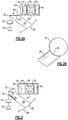
- FIG. 2A shows a non-bypass position for a bypass door 28.
- the bypass door 28 pivots about a point 30 and is driven by a motor 32 which is controlled by a control 33.
- a control 33 As shown, an upstream end 29 of the inlet into the engine meets a downstream end of the bypass door 28. In this position, the boundary layer is ingested into the engine. This position may be utilized at takeoff and climb, as well as cruise.
- bypass door 28 and the upstream end 29 of the inlet to the engine/fan rotor are both curved.
- passage 34 extends vertically beneath the engine 24 into an outlet 36. However, with the bypass door 28 in the non-bypass position air does not move into passage 34.
- engine components include a fan 42, a low pressure compressor 44, and a low pressure turbine 46 driving a fan rotor 42 and compressor 44.
- a high pressure compressor 48 is driven by a high pressure turbine 50.
- a combustor 52 is shown.
- the ingestion of the boundary layer would prove problematic to the fan rotor 42.
- the boundary layer air may be problematic.
- a top of descent condition may be such a condition. It may be advantageous to have the boundary layer bypass deployed open during the entire descent portion of the flight, from the cruise altitude to the end of descent at 1500 ft (457.2 m) altitude.
- FIG. 3 shows the movement of the bypass door 28 under such a condition.
- Door 28 pivots vertically downwardly.
- the boundary layer air may pass through this opening 31 beneath the engine into the passage 34 and be directed, as shown at 36, outwardly of the aircraft 20.
- Outlet 36 delivers air beneath a lower end 38 of the aircraft 20.
- the control 33 is programmed to know when to move the boundary layer door and will do so under conditions as mentioned above and any other conditions that would suggest bypassing the boundary layer air.
Landscapes
- Engineering & Computer Science (AREA)
- Chemical & Material Sciences (AREA)
- Combustion & Propulsion (AREA)
- Aviation & Aerospace Engineering (AREA)
- Mechanical Engineering (AREA)
- General Engineering & Computer Science (AREA)
- Physics & Mathematics (AREA)
- Fluid Mechanics (AREA)
- Structures Of Non-Positive Displacement Pumps (AREA)
Abstract
Description
- This application relates to an arrangement of gas turbine engines in a wide fuselage aircraft to selectively bypass boundary layer air around the engines.
- Gas turbine engines are known and typically include a fan delivering air into a compressor section. The air is compressed and delivered into a combustor where it is mixed with fuel and ignited. Products of this combustion pass downstream over turbine rotors driving them to rotate.
- One potential application for gas turbine engines is in next generation aircraft with boundary layer ingestion into the propulsion system. One future aircraft has a wide fuselage. The aircraft is to be driven by twin gas turbine engines mounted in the tail section. The engines extend vertically upwardly above the fuselage.
- The wide fuselage will create a large boundary layer of the air approaching the engines. Ingestion of the fuselage boundary layer enables an increase in the engine propulsive efficiency for improved fuel burn performance, but also raises challenges for the engine operation and, in particular, for the fan rotor.
- As known, an aircraft experiences a number of different conditions during a typical flight cycle. The boundary layer may be ingested adequately by the engine during numerous operational conditions where the fan speed and inlet airflow are relatively high, such as takeoff or climb.
- However, at the top of descent, a pilot will typically pull back the throttle, slowing the fan speed and reducing the inlet airflow. At the same time, the aircraft may still be at a relatively high velocity. Under such conditions, the boundary layer could become problematic with respect to engine operability or fan blade stress.
- A gas turbine engine according to one disclosed non-limiting embodiment comprises a housing having an inlet leading to a fan rotor. A bypass door is mounted upstream of the inlet to the fan rotor, and is moveable away from a non-bypass position to a bypass position to selectively bypass boundary layer air away from the inlet (and the fan rotor), for example, vertically beneath the engine.
- In an embodiment according to the previous embodiment, the bypass door is moved to pivot away, for example, vertically downwardly, from an upstream end of the inlet to the gas turbine engine and to a bypass position at which it is spaced vertically beneath the upstream end of the inlet to the engine.
- In another embodiment according to any of the previous embodiments, the bypass door and the upstream end of the inlet to the fan rotor are both curved.
- In another embodiment according to any of the previous embodiments, the bypass door is moved to the bypass position at conditions where the fan rotor is being driven more slowly than at other conditions.
- In another embodiment according to any of the previous embodiments, the conditions where the bypass door is moved to the bypass position include a top of descent condition wherein an associated aircraft is moving at a relatively high velocity.
- In another embodiment according to any of the previous embodiments, the bypass door and the upstream end of the inlet to the fan rotor are both curved.
- In another embodiment according to any of the previous embodiments, the bypass door is moved to the bypass position at conditions where the fan rotor is being driven more slowly than at other conditions.
- In another embodiment according to any of the previous embodiments, the conditions where the bypass door is moved to the bypass position include a top of descent condition wherein an associated aircraft is moving at a relatively high velocity.
- In another embodiment according to any of the previous embodiments, the bypass door is moved to the bypass position at conditions where the fan rotor is being driven more slowly than at other conditions.
- In another embodiment according to any of the previous embodiments, the conditions where the bypass door is moved to the bypass position include a top of descent condition wherein an associated aircraft is moving at a relatively high velocity.
- An aircraft according to another disclosed non-limiting embodiment comprises a relatively wide fuselage and a tail section, with a pair of gas turbine engines mounted in the tail section and extending vertically above the fuselage. The gas turbine engines have a housing with an inlet leading to a fan rotor. A bypass door is mounted upstream of the inlet to the fan rotor, and is moveable away from a non-bypass position to a bypass position to selectively bypass boundary layer air vertically beneath the engine.
- In an embodiment according to the previous embodiment, the bypass door is moving to pivot vertically downwardly from an upstream end of the inlet to the gas turbine engine and to a bypass position at which it is spaced vertically beneath the upstream end of the inlet to the engine.
- In another embodiment according to any of the previous embodiments, the bypass door and the upstream end of the inlet to the fan rotor are both curved.
- In another embodiment according to any of the previous embodiments, the bypass door is moved to the bypass position at conditions where the fan rotor is being driven more slowly than at other conditions.
- In another embodiment according to any of the previous embodiments, the conditions where the bypass door is moved to the bypass position include a top of descent condition wherein an associated aircraft is at a relatively high velocity.
- In another embodiment according to any of the previous embodiments, the bypass door and the upstream end of the inlet to the fan rotor are both curved.
- In another embodiment according to any of the previous embodiments, the bypass door is moved to the bypass position at conditions where the fan rotor is being driven more slowly than at other conditions.
- In another embodiment according to any of the previous embodiments, the conditions where the bypass door is moved to the bypass position include a top of descent condition wherein an associated aircraft is at a relatively high velocity.
- In another embodiment according to any of the previous embodiments, the bypass door is moved to the bypass position at conditions where the fan rotor is being driven more slowly than at other conditions.
- In another embodiment according to any of the previous embodiments, the conditions where the bypass door is moved to the bypass position include a top of descent condition wherein an associated aircraft is at a relatively high velocity.
- These and other features may be best understood from the following drawings and specification.
-
-
Figure 1A schematically shows a future aircraft. -
Figure 1B shows a feature of the future aircraft. -
Figure 2A shows a boundary layer bypass in a non-bypass position. -
Figure 2B shows a detail view of the 2A position. -
Figure 3 shows the bypass in a bypass position. - An aircraft 20 is illustrated in
Figure 1 having awide fuselage body 22. A pair ofgas turbine engines 24 are mounted within atail section 26. - Selectively
moveable bypass doors 28 are positioned forwardly of an inlet to theengines 24, as will be explained below. - A definition of a wide noncylindrical fuselage is illustrated in
Figure 1B . A width W defined between lateral sides of the fuselage is significantly greater than a height h. In embodiments, W may be more than twice h. Under such conditions, there will be a boundary layer atop the fuselage and approaching the inlet to theengines 24. -
Figure 2A shows a non-bypass position for abypass door 28. As shown schematically, thebypass door 28 pivots about apoint 30 and is driven by amotor 32 which is controlled by acontrol 33. As shown, anupstream end 29 of the inlet into the engine meets a downstream end of thebypass door 28. In this position, the boundary layer is ingested into the engine. This position may be utilized at takeoff and climb, as well as cruise. - As to be understood from
Figures 2A and 2B , thebypass door 28 and theupstream end 29 of the inlet to the engine/fan rotor are both curved. - As shown, a
passage 34 extends vertically beneath theengine 24 into anoutlet 36. However, with thebypass door 28 in the non-bypass position air does not move intopassage 34. - As shown schematically, engine components include a
fan 42, a low pressure compressor 44, and alow pressure turbine 46 driving afan rotor 42 and compressor 44. Ahigh pressure compressor 48 is driven by ahigh pressure turbine 50. Acombustor 52 is shown. - Under certain conditions, the ingestion of the boundary layer would prove problematic to the
fan rotor 42. In particular, if the aircraft 20 is still moving at a relatively high velocity, and the fan speed is decreased to flight idle for the descent, the boundary layer air may be problematic. As one example, a top of descent condition may be such a condition. It may be advantageous to have the boundary layer bypass deployed open during the entire descent portion of the flight, from the cruise altitude to the end of descent at 1500 ft (457.2 m) altitude. -
Figure 3 shows the movement of thebypass door 28 under such a condition.Door 28 pivots vertically downwardly. There is agap 31 between anupstream end 29 of theengine 24 and a downstream end of thebypass door 28. The boundary layer air may pass through thisopening 31 beneath the engine into thepassage 34 and be directed, as shown at 36, outwardly of the aircraft 20.Outlet 36 delivers air beneath alower end 38 of the aircraft 20. - The
control 33 is programmed to know when to move the boundary layer door and will do so under conditions as mentioned above and any other conditions that would suggest bypassing the boundary layer air. - Although an embodiment of this invention has been disclosed, a worker of ordinary skill in this art would recognize that certain modifications would come within the scope of this invention. For that reason, the following claims should be studied to determine the true scope and content of this invention.
Claims (6)
- A gas turbine engine (24) comprising:a housing having an inlet leading to a fan rotor (42); anda bypass door (28) mounted upstream of said inlet to said fan rotor (42), wherein said bypass door (28) is moveable from a non-bypass position to a bypass position to selectively bypass boundary layer air away from the inlet.
- An aircraft (20) comprising a relatively wide fuselage (22) and a tail section (26), with a pair of gas turbine engines (24) mounted in said tail section (26) and extending vertically above said fuselage (22), said gas turbine engines (24) having a housing with an inlet leading to a fan rotor (42), and a bypass door (28) mounted upstream of said inlet to said fan rotor (42), wherein said bypass door (28) is moveable from a non-bypass position to a bypass position to selectively bypass boundary layer air vertically beneath the engines (24).
- The gas turbine engine (24) or aircraft (20) as set forth in claim 1 or 2, wherein said bypass door (28) is configured to pivot (30) vertically downwardly from an upstream end (29) of said inlet to a bypass position at which the bypass door (28) is spaced vertically beneath said upstream end (29) of said inlet.
- The gas turbine engine (24) or aircraft (20) as set forth in any preceding claim, wherein said bypass door (28) meets and said upstream end (29) of said inlet are both curved.
- The gas turbine engine (24) or aircraft (20) as set forth in any preceding claim, wherein said bypass door (28) is moved to said bypass position at conditions where the fan rotor (42) is being driven more slowly than at other conditions.
- The gas turbine engine (24) or aircraft (20) as set forth in claim 5, wherein said conditions where said bypass door (28) is moved to said bypass position include a top of descent condition wherein or the associated aircraft (20) is moving at a relatively high velocity.
Applications Claiming Priority (1)
| Application Number | Priority Date | Filing Date | Title |
|---|---|---|---|
| US15/490,155 US10718272B2 (en) | 2017-04-18 | 2017-04-18 | Variable-geometry boundary layer diverter |
Publications (2)
| Publication Number | Publication Date |
|---|---|
| EP3392150A1 true EP3392150A1 (en) | 2018-10-24 |
| EP3392150B1 EP3392150B1 (en) | 2022-08-24 |
Family
ID=62025722
Family Applications (1)
| Application Number | Title | Priority Date | Filing Date |
|---|---|---|---|
| EP18168010.9A Active EP3392150B1 (en) | 2017-04-18 | 2018-04-18 | Variable-geometry boundary layer diverter |
Country Status (2)
| Country | Link |
|---|---|
| US (1) | US10718272B2 (en) |
| EP (1) | EP3392150B1 (en) |
Families Citing this family (4)
| Publication number | Priority date | Publication date | Assignee | Title |
|---|---|---|---|---|
| US10718272B2 (en) * | 2017-04-18 | 2020-07-21 | United Technologies Corporation | Variable-geometry boundary layer diverter |
| US10549845B2 (en) * | 2017-05-26 | 2020-02-04 | United Technologies Corporation | Dedicated fans for boundary layer ingestion |
| ES2949800T3 (en) * | 2020-04-29 | 2023-10-03 | Airbus Operations Sl | Rear end section of an aircraft |
| US12071224B2 (en) | 2021-11-30 | 2024-08-27 | The Boeing Company | Aircraft boundary layer ingestion using multiple fans and associated methods |
Citations (8)
| Publication number | Priority date | Publication date | Assignee | Title |
|---|---|---|---|---|
| US3109610A (en) * | 1962-09-12 | 1963-11-05 | Boeing Co | Combined aircraft air intake scoop, foreign material ingestion inhibitor, and aerodynamic flap |
| US3430640A (en) * | 1964-02-17 | 1969-03-04 | Gen Electric | Supersonic inlet |
| JPS55156800A (en) * | 1979-05-23 | 1980-12-06 | Kawasaki Heavy Ind Ltd | Air inlet port for jet engine of aircraft |
| US4655413A (en) * | 1984-02-28 | 1987-04-07 | Messerschmitt-Boelkow-Blohm Gesellschaft Mit Beschraenkter Haftung | Apparatus for improving aerodynamic flow conditions at the air intake of gas turbine engines |
| US5586735A (en) * | 1993-10-01 | 1996-12-24 | Office National D'etudies Et De Recherches Aerospatiales | Two-dimensional supersonic and hypersonic air intake, with three movable ramps, for the combustion air of an aircraft engine |
| US20030132342A1 (en) * | 2002-01-11 | 2003-07-17 | Koncsek Joseph L. | Method and apparatus for controlling aircraft inlet air flow |
| US20170066527A1 (en) * | 2015-09-04 | 2017-03-09 | The Boeing Company | Variable geometry flush boundary diverter |
| US9611034B1 (en) * | 2015-11-03 | 2017-04-04 | United Technologies Corporation | Wide fuselage aircraft with increased boundary layer ingestion |
Family Cites Families (7)
| Publication number | Priority date | Publication date | Assignee | Title |
|---|---|---|---|---|
| US2950594A (en) | 1955-06-13 | 1960-08-30 | Chance Vought Aircraft Inc | Shock wave inducing and controlling mechanism |
| US3029600A (en) | 1956-07-02 | 1962-04-17 | North American Aviation Inc | Variable supersonic inlet and by-pass system |
| US5182905A (en) * | 1990-05-11 | 1993-02-02 | General Electric Company | Method for automatic bypass operation |
| WO2008017567A1 (en) | 2006-08-11 | 2008-02-14 | Team Smartfish Gmbh | Air inlet for a jet engine |
| US8359825B2 (en) | 2008-05-21 | 2013-01-29 | Florida State University Research Foundation | Microjet creation and control of shock waves |
| US9758253B2 (en) | 2015-06-25 | 2017-09-12 | Northrop Grumman Systems Corporation | Swept gradient boundary layer diverter |
| US10718272B2 (en) * | 2017-04-18 | 2020-07-21 | United Technologies Corporation | Variable-geometry boundary layer diverter |
-
2017
- 2017-04-18 US US15/490,155 patent/US10718272B2/en active Active
-
2018
- 2018-04-18 EP EP18168010.9A patent/EP3392150B1/en active Active
Patent Citations (8)
| Publication number | Priority date | Publication date | Assignee | Title |
|---|---|---|---|---|
| US3109610A (en) * | 1962-09-12 | 1963-11-05 | Boeing Co | Combined aircraft air intake scoop, foreign material ingestion inhibitor, and aerodynamic flap |
| US3430640A (en) * | 1964-02-17 | 1969-03-04 | Gen Electric | Supersonic inlet |
| JPS55156800A (en) * | 1979-05-23 | 1980-12-06 | Kawasaki Heavy Ind Ltd | Air inlet port for jet engine of aircraft |
| US4655413A (en) * | 1984-02-28 | 1987-04-07 | Messerschmitt-Boelkow-Blohm Gesellschaft Mit Beschraenkter Haftung | Apparatus for improving aerodynamic flow conditions at the air intake of gas turbine engines |
| US5586735A (en) * | 1993-10-01 | 1996-12-24 | Office National D'etudies Et De Recherches Aerospatiales | Two-dimensional supersonic and hypersonic air intake, with three movable ramps, for the combustion air of an aircraft engine |
| US20030132342A1 (en) * | 2002-01-11 | 2003-07-17 | Koncsek Joseph L. | Method and apparatus for controlling aircraft inlet air flow |
| US20170066527A1 (en) * | 2015-09-04 | 2017-03-09 | The Boeing Company | Variable geometry flush boundary diverter |
| US9611034B1 (en) * | 2015-11-03 | 2017-04-04 | United Technologies Corporation | Wide fuselage aircraft with increased boundary layer ingestion |
Also Published As
| Publication number | Publication date |
|---|---|
| US10718272B2 (en) | 2020-07-21 |
| EP3392150B1 (en) | 2022-08-24 |
| US20180298829A1 (en) | 2018-10-18 |
Similar Documents
| Publication | Publication Date | Title |
|---|---|---|
| US11391240B2 (en) | Gas turbine engine bifurcation located fan variable area nozzle | |
| US9878796B2 (en) | Hybrid drive for gas turbine engine | |
| CN107848629B (en) | Aircraft including a propulsion assembly with a fan on the rear of the fuselage | |
| EP2074317B1 (en) | Nacelle assembly for a gas turbine engine comprising a pylon located in the fan bypass flow path with a variable area flow system | |
| EP3284942B1 (en) | Direct drive aft fan engine | |
| EP1878904A2 (en) | Thrust reverser assembly for a gas turbine engine and method of operating same | |
| US20130104522A1 (en) | Gas turbine engine with variable pitch first stage fan section | |
| EP3406519B1 (en) | Dedicated fans for boundary layer ingestion | |
| EP2177735A2 (en) | Turbofan | |
| US10309315B2 (en) | Variable area nozzle assisted gas turbine engine restarting | |
| EP3392150B1 (en) | Variable-geometry boundary layer diverter | |
| EP2932068A1 (en) | Gas turbine engine with cooling scheme for drive gear system and pitch control | |
| EP2924247B1 (en) | Hybrid drive for gas turbine engine | |
| US11078870B2 (en) | Method and system for a stowable bell-mouth scoop | |
| EP2074310B1 (en) | Controlling the aerodynamic drag of a gas turbine engine during a shutdown state | |
| EP3043033A1 (en) | Gas turbine engine with improved fuel efficiency | |
| EP2809936B1 (en) | Gas turbine engine with improved fuel efficiency |
Legal Events
| Date | Code | Title | Description |
|---|---|---|---|
| PUAI | Public reference made under article 153(3) epc to a published international application that has entered the european phase |
Free format text: ORIGINAL CODE: 0009012 |
|
| STAA | Information on the status of an ep patent application or granted ep patent |
Free format text: STATUS: THE APPLICATION HAS BEEN PUBLISHED |
|
| AK | Designated contracting states |
Kind code of ref document: A1 Designated state(s): AL AT BE BG CH CY CZ DE DK EE ES FI FR GB GR HR HU IE IS IT LI LT LU LV MC MK MT NL NO PL PT RO RS SE SI SK SM TR |
|
| AX | Request for extension of the european patent |
Extension state: BA ME |
|
| STAA | Information on the status of an ep patent application or granted ep patent |
Free format text: STATUS: REQUEST FOR EXAMINATION WAS MADE |
|
| 17P | Request for examination filed |
Effective date: 20190424 |
|
| RBV | Designated contracting states (corrected) |
Designated state(s): AL AT BE BG CH CY CZ DE DK EE ES FI FR GB GR HR HU IE IS IT LI LT LU LV MC MK MT NL NO PL PT RO RS SE SI SK SM TR |
|
| STAA | Information on the status of an ep patent application or granted ep patent |
Free format text: STATUS: EXAMINATION IS IN PROGRESS |
|
| 17Q | First examination report despatched |
Effective date: 20190807 |
|
| RAP1 | Party data changed (applicant data changed or rights of an application transferred) |
Owner name: RAYTHEON TECHNOLOGIES CORPORATION |
|
| GRAP | Despatch of communication of intention to grant a patent |
Free format text: ORIGINAL CODE: EPIDOSNIGR1 |
|
| STAA | Information on the status of an ep patent application or granted ep patent |
Free format text: STATUS: GRANT OF PATENT IS INTENDED |
|
| INTG | Intention to grant announced |
Effective date: 20220322 |
|
| GRAS | Grant fee paid |
Free format text: ORIGINAL CODE: EPIDOSNIGR3 |
|
| GRAA | (expected) grant |
Free format text: ORIGINAL CODE: 0009210 |
|
| STAA | Information on the status of an ep patent application or granted ep patent |
Free format text: STATUS: THE PATENT HAS BEEN GRANTED |
|
| AK | Designated contracting states |
Kind code of ref document: B1 Designated state(s): AL AT BE BG CH CY CZ DE DK EE ES FI FR GB GR HR HU IE IS IT LI LT LU LV MC MK MT NL NO PL PT RO RS SE SI SK SM TR |
|
| REG | Reference to a national code |
Ref country code: CH Ref legal event code: EP |
|
| REG | Reference to a national code |
Ref country code: IE Ref legal event code: FG4D |
|
| REG | Reference to a national code |
Ref country code: AT Ref legal event code: REF Ref document number: 1513500 Country of ref document: AT Kind code of ref document: T Effective date: 20220915 Ref country code: DE Ref legal event code: R096 Ref document number: 602018039594 Country of ref document: DE |
|
| REG | Reference to a national code |
Ref country code: LT Ref legal event code: MG9D |
|
| REG | Reference to a national code |
Ref country code: NL Ref legal event code: MP Effective date: 20220824 |
|
| PG25 | Lapsed in a contracting state [announced via postgrant information from national office to epo] |
Ref country code: SE Free format text: LAPSE BECAUSE OF FAILURE TO SUBMIT A TRANSLATION OF THE DESCRIPTION OR TO PAY THE FEE WITHIN THE PRESCRIBED TIME-LIMIT Effective date: 20220824 Ref country code: RS Free format text: LAPSE BECAUSE OF FAILURE TO SUBMIT A TRANSLATION OF THE DESCRIPTION OR TO PAY THE FEE WITHIN THE PRESCRIBED TIME-LIMIT Effective date: 20220824 Ref country code: PT Free format text: LAPSE BECAUSE OF FAILURE TO SUBMIT A TRANSLATION OF THE DESCRIPTION OR TO PAY THE FEE WITHIN THE PRESCRIBED TIME-LIMIT Effective date: 20221226 Ref country code: NO Free format text: LAPSE BECAUSE OF FAILURE TO SUBMIT A TRANSLATION OF THE DESCRIPTION OR TO PAY THE FEE WITHIN THE PRESCRIBED TIME-LIMIT Effective date: 20221124 Ref country code: NL Free format text: LAPSE BECAUSE OF FAILURE TO SUBMIT A TRANSLATION OF THE DESCRIPTION OR TO PAY THE FEE WITHIN THE PRESCRIBED TIME-LIMIT Effective date: 20220824 Ref country code: LV Free format text: LAPSE BECAUSE OF FAILURE TO SUBMIT A TRANSLATION OF THE DESCRIPTION OR TO PAY THE FEE WITHIN THE PRESCRIBED TIME-LIMIT Effective date: 20220824 Ref country code: LT Free format text: LAPSE BECAUSE OF FAILURE TO SUBMIT A TRANSLATION OF THE DESCRIPTION OR TO PAY THE FEE WITHIN THE PRESCRIBED TIME-LIMIT Effective date: 20220824 Ref country code: FI Free format text: LAPSE BECAUSE OF FAILURE TO SUBMIT A TRANSLATION OF THE DESCRIPTION OR TO PAY THE FEE WITHIN THE PRESCRIBED TIME-LIMIT Effective date: 20220824 |
|
| REG | Reference to a national code |
Ref country code: AT Ref legal event code: MK05 Ref document number: 1513500 Country of ref document: AT Kind code of ref document: T Effective date: 20220824 |
|
| PG25 | Lapsed in a contracting state [announced via postgrant information from national office to epo] |
Ref country code: PL Free format text: LAPSE BECAUSE OF FAILURE TO SUBMIT A TRANSLATION OF THE DESCRIPTION OR TO PAY THE FEE WITHIN THE PRESCRIBED TIME-LIMIT Effective date: 20220824 Ref country code: IS Free format text: LAPSE BECAUSE OF FAILURE TO SUBMIT A TRANSLATION OF THE DESCRIPTION OR TO PAY THE FEE WITHIN THE PRESCRIBED TIME-LIMIT Effective date: 20221224 Ref country code: HR Free format text: LAPSE BECAUSE OF FAILURE TO SUBMIT A TRANSLATION OF THE DESCRIPTION OR TO PAY THE FEE WITHIN THE PRESCRIBED TIME-LIMIT Effective date: 20220824 Ref country code: GR Free format text: LAPSE BECAUSE OF FAILURE TO SUBMIT A TRANSLATION OF THE DESCRIPTION OR TO PAY THE FEE WITHIN THE PRESCRIBED TIME-LIMIT Effective date: 20221125 |
|
| PG25 | Lapsed in a contracting state [announced via postgrant information from national office to epo] |
Ref country code: SM Free format text: LAPSE BECAUSE OF FAILURE TO SUBMIT A TRANSLATION OF THE DESCRIPTION OR TO PAY THE FEE WITHIN THE PRESCRIBED TIME-LIMIT Effective date: 20220824 Ref country code: RO Free format text: LAPSE BECAUSE OF FAILURE TO SUBMIT A TRANSLATION OF THE DESCRIPTION OR TO PAY THE FEE WITHIN THE PRESCRIBED TIME-LIMIT Effective date: 20220824 Ref country code: ES Free format text: LAPSE BECAUSE OF FAILURE TO SUBMIT A TRANSLATION OF THE DESCRIPTION OR TO PAY THE FEE WITHIN THE PRESCRIBED TIME-LIMIT Effective date: 20220824 Ref country code: DK Free format text: LAPSE BECAUSE OF FAILURE TO SUBMIT A TRANSLATION OF THE DESCRIPTION OR TO PAY THE FEE WITHIN THE PRESCRIBED TIME-LIMIT Effective date: 20220824 Ref country code: CZ Free format text: LAPSE BECAUSE OF FAILURE TO SUBMIT A TRANSLATION OF THE DESCRIPTION OR TO PAY THE FEE WITHIN THE PRESCRIBED TIME-LIMIT Effective date: 20220824 Ref country code: AT Free format text: LAPSE BECAUSE OF FAILURE TO SUBMIT A TRANSLATION OF THE DESCRIPTION OR TO PAY THE FEE WITHIN THE PRESCRIBED TIME-LIMIT Effective date: 20220824 |
|
| REG | Reference to a national code |
Ref country code: DE Ref legal event code: R097 Ref document number: 602018039594 Country of ref document: DE |
|
| PG25 | Lapsed in a contracting state [announced via postgrant information from national office to epo] |
Ref country code: SK Free format text: LAPSE BECAUSE OF FAILURE TO SUBMIT A TRANSLATION OF THE DESCRIPTION OR TO PAY THE FEE WITHIN THE PRESCRIBED TIME-LIMIT Effective date: 20220824 Ref country code: EE Free format text: LAPSE BECAUSE OF FAILURE TO SUBMIT A TRANSLATION OF THE DESCRIPTION OR TO PAY THE FEE WITHIN THE PRESCRIBED TIME-LIMIT Effective date: 20220824 |
|
| P01 | Opt-out of the competence of the unified patent court (upc) registered |
Effective date: 20230521 |
|
| PG25 | Lapsed in a contracting state [announced via postgrant information from national office to epo] |
Ref country code: AL Free format text: LAPSE BECAUSE OF FAILURE TO SUBMIT A TRANSLATION OF THE DESCRIPTION OR TO PAY THE FEE WITHIN THE PRESCRIBED TIME-LIMIT Effective date: 20220824 |
|
| PLBE | No opposition filed within time limit |
Free format text: ORIGINAL CODE: 0009261 |
|
| STAA | Information on the status of an ep patent application or granted ep patent |
Free format text: STATUS: NO OPPOSITION FILED WITHIN TIME LIMIT |
|
| 26N | No opposition filed |
Effective date: 20230525 |
|
| PG25 | Lapsed in a contracting state [announced via postgrant information from national office to epo] |
Ref country code: SI Free format text: LAPSE BECAUSE OF FAILURE TO SUBMIT A TRANSLATION OF THE DESCRIPTION OR TO PAY THE FEE WITHIN THE PRESCRIBED TIME-LIMIT Effective date: 20220824 |
|
| REG | Reference to a national code |
Ref country code: CH Ref legal event code: PL |
|
| PG25 | Lapsed in a contracting state [announced via postgrant information from national office to epo] |
Ref country code: LU Free format text: LAPSE BECAUSE OF NON-PAYMENT OF DUE FEES Effective date: 20230418 |
|
| REG | Reference to a national code |
Ref country code: BE Ref legal event code: MM Effective date: 20230430 |
|
| PG25 | Lapsed in a contracting state [announced via postgrant information from national office to epo] |
Ref country code: MC Free format text: LAPSE BECAUSE OF FAILURE TO SUBMIT A TRANSLATION OF THE DESCRIPTION OR TO PAY THE FEE WITHIN THE PRESCRIBED TIME-LIMIT Effective date: 20220824 |
|
| PG25 | Lapsed in a contracting state [announced via postgrant information from national office to epo] |
Ref country code: MC Free format text: LAPSE BECAUSE OF FAILURE TO SUBMIT A TRANSLATION OF THE DESCRIPTION OR TO PAY THE FEE WITHIN THE PRESCRIBED TIME-LIMIT Effective date: 20220824 Ref country code: LI Free format text: LAPSE BECAUSE OF NON-PAYMENT OF DUE FEES Effective date: 20230430 Ref country code: CH Free format text: LAPSE BECAUSE OF NON-PAYMENT OF DUE FEES Effective date: 20230430 |
|
| REG | Reference to a national code |
Ref country code: IE Ref legal event code: MM4A |
|
| PG25 | Lapsed in a contracting state [announced via postgrant information from national office to epo] |
Ref country code: BE Free format text: LAPSE BECAUSE OF NON-PAYMENT OF DUE FEES Effective date: 20230430 |
|
| PG25 | Lapsed in a contracting state [announced via postgrant information from national office to epo] |
Ref country code: IE Free format text: LAPSE BECAUSE OF NON-PAYMENT OF DUE FEES Effective date: 20230418 |
|
| PG25 | Lapsed in a contracting state [announced via postgrant information from national office to epo] |
Ref country code: IE Free format text: LAPSE BECAUSE OF NON-PAYMENT OF DUE FEES Effective date: 20230418 |
|
| PG25 | Lapsed in a contracting state [announced via postgrant information from national office to epo] |
Ref country code: IT Free format text: LAPSE BECAUSE OF FAILURE TO SUBMIT A TRANSLATION OF THE DESCRIPTION OR TO PAY THE FEE WITHIN THE PRESCRIBED TIME-LIMIT Effective date: 20220824 |
|
| PG25 | Lapsed in a contracting state [announced via postgrant information from national office to epo] |
Ref country code: BG Free format text: LAPSE BECAUSE OF FAILURE TO SUBMIT A TRANSLATION OF THE DESCRIPTION OR TO PAY THE FEE WITHIN THE PRESCRIBED TIME-LIMIT Effective date: 20220824 |
|
| PG25 | Lapsed in a contracting state [announced via postgrant information from national office to epo] |
Ref country code: BG Free format text: LAPSE BECAUSE OF FAILURE TO SUBMIT A TRANSLATION OF THE DESCRIPTION OR TO PAY THE FEE WITHIN THE PRESCRIBED TIME-LIMIT Effective date: 20220824 |
|
| PGFP | Annual fee paid to national office [announced via postgrant information from national office to epo] |
Ref country code: DE Payment date: 20250319 Year of fee payment: 8 |
|
| PG25 | Lapsed in a contracting state [announced via postgrant information from national office to epo] |
Ref country code: CY Free format text: LAPSE BECAUSE OF FAILURE TO SUBMIT A TRANSLATION OF THE DESCRIPTION OR TO PAY THE FEE WITHIN THE PRESCRIBED TIME-LIMIT; INVALID AB INITIO Effective date: 20180418 |
|
| PG25 | Lapsed in a contracting state [announced via postgrant information from national office to epo] |
Ref country code: HU Free format text: LAPSE BECAUSE OF FAILURE TO SUBMIT A TRANSLATION OF THE DESCRIPTION OR TO PAY THE FEE WITHIN THE PRESCRIBED TIME-LIMIT; INVALID AB INITIO Effective date: 20180418 |
|
| REG | Reference to a national code |
Ref country code: DE Ref legal event code: R081 Ref document number: 602018039594 Country of ref document: DE Owner name: RTX CORPORATION (N.D.GES.D. STAATES DELAWARE),, US Free format text: FORMER OWNER: RAYTHEON TECHNOLOGIES CORP., FARMINGTON, CT, US |
|
| PG25 | Lapsed in a contracting state [announced via postgrant information from national office to epo] |
Ref country code: TR Free format text: LAPSE BECAUSE OF FAILURE TO SUBMIT A TRANSLATION OF THE DESCRIPTION OR TO PAY THE FEE WITHIN THE PRESCRIBED TIME-LIMIT Effective date: 20220824 |
|
| PGFP | Annual fee paid to national office [announced via postgrant information from national office to epo] |
Ref country code: GB Payment date: 20260319 Year of fee payment: 9 |
|
| PGFP | Annual fee paid to national office [announced via postgrant information from national office to epo] |
Ref country code: FR Payment date: 20260320 Year of fee payment: 9 |