EP3392099A1 - Washer fluid system - Google Patents
Washer fluid system Download PDFInfo
- Publication number
- EP3392099A1 EP3392099A1 EP17167377.5A EP17167377A EP3392099A1 EP 3392099 A1 EP3392099 A1 EP 3392099A1 EP 17167377 A EP17167377 A EP 17167377A EP 3392099 A1 EP3392099 A1 EP 3392099A1
- Authority
- EP
- European Patent Office
- Prior art keywords
- filling unit
- washer fluid
- fluid system
- hatch
- housing
- Prior art date
- Legal status (The legal status is an assumption and is not a legal conclusion. Google has not performed a legal analysis and makes no representation as to the accuracy of the status listed.)
- Granted
Links
Images




Classifications
-
- B—PERFORMING OPERATIONS; TRANSPORTING
- B60—VEHICLES IN GENERAL
- B60S—SERVICING, CLEANING, REPAIRING, SUPPORTING, LIFTING, OR MANOEUVRING OF VEHICLES, NOT OTHERWISE PROVIDED FOR
- B60S1/00—Cleaning of vehicles
- B60S1/02—Cleaning windscreens, windows or optical devices
- B60S1/46—Cleaning windscreens, windows or optical devices using liquid; Windscreen washers
- B60S1/48—Liquid supply therefor
- B60S1/50—Arrangement of reservoir
Definitions
- the present disclosure relates to a washer fluid system for a vehicle.
- the disclosure further relates to a vehicle comprising the washer fluid system.
- washer fluid is utilized to help keeping the windscreen clean. Washer fluid may also be utilized for other vehicular windows, like for the rear window, or for the glasses of lights, such as headlights. Further, washer fluid may be utilized to give one or more sensor of the vehicle an undisturbed field of view.
- a washer fluid system comprises a reservoir adapted to contain washer fluid, which reservoir is located below the bonnet. Further, a filling unit with an aperture utilized to fill washer fluid into the washer fluid system is typically located in the vicinity of the reservoir. Therefore, a person wanting to fill the washer fluid system with more washer fluid usually has to open the bonnet and lean in over the engine compartment in order to reach the filling unit and be able to pour washer fluid into it. Opening the bonnet as well as the handling inside the engine compartment involves a number of steps before filling is ready and the vehicle is ready to drive off again. Moreover, there is a high risk of getting dirty by touching against a possibly dirty vehicle.
- Washer fluid may be filled through a filling unit, which is accessible from the outside of the vehicle without opening the bonnet. This is achieved in that the filling unit is arranged below one of the windshield wipers in the region between the windshield and the bonnet. In an inactive position of the filling unit, it is at least partially covered by an end portion of the bonnet. The filling unit can be moved from its inactive position into an operating position accessible from the outside of the vehicle, when the windscreen wiper is pivoted upwards. In this operating position, the washer fluid can be filled into the filling unit.
- the object of the present disclosure is to overcome or ameliorate at least one of the disadvantages of the prior art, or to provide a useful alternative.
- the invention relates to a washer fluid system for a vehicle.
- the washer fluid system comprises a reservoir adapted to contain washer fluid, a filling unit comprising an aperture for filling washer fluid into the reservoir and a conduit providing a fluid connection from the filling unit to the reservoir.
- the filling unit is transitable between an inactive position and a fill position.
- the washer fluid system further comprises a hatch being transitable between a closed position and an open position.
- the filling unit is attached to, or integrated with, the hatch, such that the filling unit is displaced together with the hatch when transiting from the closed position to the open position, the filling unit thereby transiting from the inactive position to the fill position.
- Directions as used herein, e.g. horizontal, vertical, lateral, relate to when the washer fluid system is mounted in the vehicle, which stands on flat ground.
- the washer fluid system may be manufactured, stored, transported and sold as a separate unit. In that case, the directions may differ from when mounted in the vehicle.
- the hatch and the filling unit of the washer fluid system disclosed herein are accessible from the outside of the vehicle without opening the bonnet.
- the closed position of the hatch corresponds to the inactive position of the filling unit and the open position of the hatch corresponds to the fill position of the filling unit.
- the fill position may also be called the operating position.
- the inactive position of the filling unit is used when driving or parking the vehicle.
- the filling unit is then hidden behind the hatch. Thereby the filling unit is protected from the ambient environment by the hatch. Further, the hatch may be utilized to minimize the risk that an unauthorized person would tamper with or steal washer fluid.
- the hatch may e.g. be opened by the person going to fill washer fluid by pushing the hatch inwards, such that it is released and pops out.
- the person may press a button or other control element on the inside or outside of the vehicle.
- the hatch may then be manually displaced to the open position by the person or the hatch may be biased towards the open position by e.g. a spring.
- the person can fill the washer fluid, e.g. until a washer fluid level is visible in the filling unit or to a predefined maximum level. Thereafter the person may close the hatch, thereby returning it to the closed position and hence also returning the filling unit to the inactive position.
- the aperture of the filling unit preferably has an oblong shape, which facilitates filling of the washer fluid.
- the aperture is further preferably large enough to help the person performing the filling not to pour any washer fluid outside of the aperture.
- the hatch may be configured to form a part of a body of the vehicle, e.g. a part of a fender, door or bonnet of the vehicle.
- the hatch may therefore have a corresponding surface treatment as the body of the vehicle, e.g. having the same colour or material.
- the hatch may form a part of a front fender, but the hatch may also be located elsewhere in the vehicle, e.g. forming a part of the grill, a bonnet, any of the doors or a rear fender. It has been found convenient to provide the hatch at the same side of the vehicle as a tank filler cap, such that washer fluid and fuel can be filled from the same side of the vehicle.
- a side wall of the filling unit may be attached to, or be integrated in, the hatch.
- the hatch may in that case constitute the side wall of the filling unit.
- the aperture of the filling unit will be perpendicular or substantially perpendicular to the extension plane of the hatch.
- the hatch may be transitable between the closed position and the open position by means of a displacement comprising a pivotal displacement around a pivot arm, the pivot arm preferably being comprised in, or constituting a part of, the filling unit.
- the filling unit makes a displacement comprising a pivotal displacement from the inactive position to the fill position, since the filling unit is attached to, or integrated with, the hatch.
- the pivot arm facilitates the pivotal displacement.
- the pivotal displacement may be in the range of 45-135 degrees, e.g. in the range of 60-120 degrees.
- the hatch may comprise its own hinges.
- the displacement between the closed position and the open position of the hatch, and thus also of the displacement of the filling unit may comprise a linear displacement.
- the filling unit may comprise a tubular structure, adapted to extend in a vertical direction to connect to the conduit.
- a side wall of the tubular structure facing in the direction towards the aperture of the filling unit may be at least partly open to allow flow of the washer fluid into the tubular structure.
- the tubular structure is thus configured such that the washer fluid can flow from the aperture, via the tubular structure and the conduit to the reservoir during filling of washer fluid.
- the tubular structure may constitute the pivot arm of the pivotal displacement, such that a hinge is integrated in the filling unit.
- the tubular structure may combine two different functions: providing the pivotal displacement and forming a fluid connection for the washer fluid.
- the tubular structure may be located around the pivot arm, preferably such that the tubular structure is coaxial with the pivot arm.
- the pivot arm may be arranged in the filling unit but separate from the tubular structure. Nevertheless, the pivot arm preferably forms an integral part of the filling unit, e.g. being moulded as an integral unit.
- the conduit may be flexible, e.g. by being curvable and/or by having a variable length.
- the conduit may e.g. have a flexible wall, such as a tube with an expandable corrugated wall, which is easily flexed.
- the filling unit is attached to, or integrated with, the hatch. Due to the flexibility of the conduit, the filling unit is able to be displaced together with the hatch, when the hatch is transited to the open position.
- the conduit may be curved to follow the displacement of the hatch, e.g. if the hatch is pivoted to its open position.
- the flexible portion of the conduit may e.g. be curved by at least 90 degrees or at least 135 degrees, depending on how far the hatch is pivoted.
- the conduit may be flexible by having a variable length, wherein the length is longer in the fill position of the filling unit than in the inactive position of the filling unit.
- the conduit, or the portion of the conduit may e.g. have an expandable corrugated wall, which is expandable and/or may comprise telescoping portions. Thereby the filling unit may be pulled out when opening the hatch and displacing it to the open position.
- the washer fluid system may comprise a housing adapted to contain the filling unit when in the inactive position.
- the housing has an opening, through which the filling unit is transitable to the fill position, the hatch in the closed position being adapted to cover the opening of the housing. Thereby the filling unit is completely contained in the housing when in the inactive position, e.g. when driving or parking.
- the housing and the filling unit may form a common module, which facilitates mounting in the vehicle, since the module may be mounted as one unit.
- the housing may be located behind a front fender, a rear fender, any of the doors grill, or below a bonnet.
- the hatch may be formed as a part of the housing. A whole side wall of the housing, or only a portion thereof, may be constituted by the hatch.
- the hatch may be hingedly connected to the housing.
- the hinge may be comprised in the filling unit, e.g. being constituted by the tubular structure.
- the hatch may have its own hinge or hinges.
- the housing may comprise a ceiling adapted to form a cover of the aperture of the filling unit, when the filling unit is in the inactive position.
- the ceiling helps to prevent that washer fluid is splashed during driving on e.g. a bumpy road.
- a side wall of the filling unit may comprise an upper wall portion being substantially horizontal and the ceiling of the housing may comprise a top sealing adapted to seal between the ceiling and the upper wall portion of the filling unit around at least a portion of a circumference of the aperture of the filling unit, preferably around the whole circumference, when the filling unit is in the inactive position.
- the top sealing is adapted to seal in the vertical direction.
- the top sealing together with the ceiling of the housing help to prevent that washer fluid is splashed during driving on e.g. a bumpy road.
- a width of the upper wall portion may be in the range of 2-20 mm, preferably 5-15 mm.
- the upper wall portion may comprise a corresponding sealing facing upwards against the ceiling of the housing.
- a side wall of the filling unit may comprise a side sealing adapted to seal between the filling unit and a side wall of the housing.
- the side sealing is adapted to seal in the lateral direction.
- the side sealing together with the ceiling of the housing help to prevent that washer fluid is splashed during driving on e.g. a bumpy road.
- the side sealing is located close to the aperture of the filling unit, i.e. close to the upper edge of the side wall of the filling unit.
- the side sealing may face in a direction towards the vehicle.
- the side sealing may be located at an inner side wall of the portion of the filling unit, which inner side wall is attached to, or integrated in the hatch, and at an outer side wall for the rest of the circumference around the aperture of the filling unit.
- the side sealing of the filling unit may be integrated in the filling unit, e.g. by means of two-component injection moulding.
- the side wall of the housing may comprise a wall sealing adapted to seal between the filling unit and the side wall of the housing.
- the wall sealing together with the ceiling of the housing help to prevent that washer fluid is splashed during driving on e.g. a bumpy road.
- the wall sealing is arranged to cooperate with a corresponding side sealing of the filling unit.
- top sealing of the housing and/or the wall sealing of the housing may be integrated in the housing, e.g. by means of two-component injection moulding.
- a bottom wall of the housing may comprise at least one drainage hole providing a fluid connection from the filling unit to the conduit.
- a bottom of the filling unit e.g. at the tubular structure, may comprise at least one drainage hole, through which the washer fluid can pass when being filled.
- One, two, three, four or more drainage holes may be utilized.
- the hatch may comprise at least one guide, e.g. a rail, adapted to cooperate with a protruding member, e.g. a pin, comprised in the filling unit.
- the protruding member may be arranged to be able to slide in the guide, such that the protruding member can follow the displacement of the hatch by sliding along the guide, when the hatch is transited from the closed position to the open position.
- the protruding member may e.g. have a mushroom shape with a head with a larger diameter than a stem, with the head having a large enough diameter to fit in the guide but no to come out through the guide.
- the conduit may be flexible to facilitate this displacement, see above.
- the washer fluid system may comprise one, two, three or more guides with a corresponding number of protruding members.
- the invention further relates to a vehicle comprising the washer fluid system as described herein.
- FIG 1 illustrates a vehicle 1 according to the present invention.
- the vehicle 1 comprises a washer fluid system 3 according to a first embodiment of the present invention.
- the washer fluid system comprises a reservoir 5 adapted to contain washer fluid, a filling unit 7 comprising an aperture 9 for filling washer fluid into the reservoir 5 and a conduit 11 connecting the filling unit 7 to the reservoir 5.
- Figure 2 more detailedly shows the filling unit 7 and a part of the conduit 11.
- Directions as used herein, e.g. horizontal, vertical, lateral, relate to when the washer fluid system 3 is mounted in the vehicle 1, which stands on flat ground.
- the washer fluid system 3 may be manufactured, stored, transported and sold as a separate unit. In that case the directions may differ from when mounted in the vehicle 1.
- a hatch 13 forms a part of a body of the vehicle 1.
- the hatch 13 therefore typically has a corresponding surface treatment as the body of the vehicle 1, e.g. having the same colour.
- the hatch 13 forms a part of a front fender 15, but the hatch may also be located elsewhere in the vehicle, e.g. forming a part of the grill, a bonnet, any of the doors or a rear fender. It has been found convenient to provide the hatch 13 at the same side of the vehicle 1 as a tank filler cap 17, such that washer fluid and fuel can be filled from the same side of the vehicle 1.
- the hatch 13 has a closed position, as illustrated in Figure 1 , and an open position, as illustrated in Figure 2 .
- the filling unit 7 is attached to the hatch 13, by a side wall of the filling unit being attached to the hatch 13, such that the filling unit 7 is displaced together with the hatch 13 when the hatch 13 transits from the closed position to the open position, the filling unit 7 thereby transiting from an inactive position, as illustrated in Figure 1 , to a fill position, as illustrated in Figure 2 .
- In the fill position it is easy to fill washer fluid into the filling unit 7, since the filling unit 7 is easily accessible.
- the washer fluid system 3 further comprises a housing 19 located behind the hatch 13.
- the housing comprises a ceiling 21, a side wall 23 and a bottom wall 25.
- the housing 19 contains the filling unit 7 when in the inactive position.
- the housing 19 comprises an opening 27, through which the filling unit 7 is transitable from the inactive position to the fill position.
- the hatch 13 is in the closed position adapted to cover the opening 27 of the housing 19. Thereby the filling unit 7 is completely contained in the housing 19, e.g. when driving or parking the vehicle 1.
- the aperture 9 of the filling unit 7 preferably has an oblong shape, as in the illustrated embodiment of Figure 2 , which facilitates filling of the washer fluid.
- the aperture 9 is further preferably large enough to help a person performing the filling not to pour any washer fluid outside of the aperture 9.
- a side wall of the filling unit 7 comprises an upper wall portion 10, which is substantially horizontal.
- a width w of the upper wall portion 10 may be in the range of 2-20 mm, preferably 5-15 mm.
- the hatch 13 may be opened by the person going to fill washer fluid by pushing the hatch 13 inwards, such that it is released and pops out. Alternatively, the person may press a button or other control element on the inside or outside of the vehicle 1. The hatch 13 may then be manually displaced to the open position by the person or the hatch 13 may be biased towards the open position by e.g. a spring. Thereafter the person can fill the washer fluid, e.g. until a washer fluid level is visible in the filling unit 7. Preferably, the washer fluid level is not filled more than until it reaches a level 29, e.g. labelled as MAX. Thereafter the person closes the hatch 13. Hence, with the washer fluid system 3 according to the invention, it is possible to considerably reduce the number of steps for filling washer fluid as compared to a prior art washer fluid system.
- the hatch 13 is opened by means of a pivotal displacement, which occurs around a pivot arm, which forms part of the filling unit 7, herein illustrated as being an integral part of the filling unit 7.
- the pivot arm constitutes or comprises a tubular structure 31, which extends in a vertical direction to connect to the conduit 11.
- the filling unit 7 itself comprises a hinge.
- a side wall of the tubular structure 31 facing in a direction towards the aperture 9 of the filling unit 7 is at least partly open, such that the washer fluid can flow from the aperture 9, via the tubular structure 31 and the conduit 11 to the reservoir 5 during filling of washer fluid.
- the ceiling 21 of the housing 19 comprises a top sealing 33, which is located in such a way that the top sealing 33 seals between the upper wall portion 10 of the filling unit 7 and the ceiling 21, when the filling unit 7 is in its inactive position.
- the top sealing 33 seals in the vertical direction.
- the top sealing 33 is being integrated into the housing 19 when manufacturing the housing 19, e.g. by means of two-component moulding. It would also be possible, however not illustrated, to have a corresponding sealing at the upper wall portion 10.
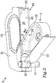
- the pivot arm 35 may be arranged separately from the tubular structure 31, as is illustrated in Figure 3 .
- the pivot arm 35 preferably forms an integral part of the filling unit 7.
- the bottom wall of the housing 19 comprises an opening 37, which is shaped as a portion of a circle to allow the pivotal displacement of the filling unit 7.
- first and second side sealings 39, 41 are adapted to seal in the lateral direction between a filling unit 7' and a housing 19'.
- a first side wall 43 of the filling unit 7' is attached to the hatch 13'.
- the second, third and fourth side walls 45, 47, 49 are directed towards the side wall 23' of the housing 19'.
- the fourth side wall 49 of the filling unit 7' has an opening 51 for leading the washer fluid to the conduit 11.
- the side walls 43, 45, 47, 49 are vertical or substantially vertical.
- the flow of washer fluid is similar as for the washer fluid system illustrated in Figure 2 .
- the first side wall 43 located at the hatch 13' protrudes above the other side walls 45, 47, 49.
- the first side sealing 39 is located in the protruding portion of the first side wall 43, such that the first side sealing 39 is located above the other side walls 45, 47, 49 and faces towards the housing 19'.
- the housing 19' comprises a corresponding first wall sealing 53 facing outwards. When the filling unit 7' is in the inactive position, the first side sealing 39 of the filling unit 7' thus seals against the first wall sealing 53 of the housing 19'.
- An outside of the side walls 45, 47, 49, i.e. the side facing the housing 19' comprises a second side sealing 41.
- the second side sealing 41 is located vertically below the first sealing 39.
- the housing 19' comprises a corresponding second wall sealing 55 facing outwards.
- the second side sealing 41 of the filling unit 7' thus seals against the second wall sealing 55 of the housing 19'.
- the second wall sealing 55 of the housing 19' is thus located vertically below the first wall sealing 53 and laterally closer to a centre of the vehicle 1.
- the side wall 23'of the housing thus has a stepwise configuration, with an upper portion 23a' providing a seat for the first wall sealing 53 and a lower portion 23b' providing a seat for the second wall sealing 55 and a step portion 23c' therebetween.
- the step portion 23c' will act as a cover for the aperture of the filling unit 7' in the inactive position.
- the configuration of the step portion 23c' e.g. its inclination is selected to correspond to that of the filling unit 7' in order to provide the desired sealing of the filling unit 7' in the inactive position.
- the first side sealing 39 and the second side sealing 41 of the filling unit 7' are being integrated into the filling unit 7', when manufacturing it e.g. by means of two-component moulding.
- the first wall sealing 53 and the second wall sealing 55 are being integrated into the housing 19' when manufacturing the housing 19', e.g. by means of two-component moulding. It would also be feasible to only use sealings in either the side wall of the filling unit 7' or in the side wall 23' of the housing 19'.
- FIG 5a illustrates yet another embodiment of the washer fluid system 3", in which the conduit 11" is flexible, since a portion of it has a flexible wall, illustrated as a tube with an expandable corrugated wall.
- the hatch 13" is hingedly connected to the vehicle body, e.g. to the housing.
- the filling unit 7" is attached to the hatch 13". Due to the flexibility of the conduit 11", the filling unit 7" is displaced together with the hatch 13", when the hatch 13" is transited to the open position. During this displacement to the fill position of the filling unit 7", the conduit 11" is being curved to follow the displacement of the hatch 13". Further, the length of the conduit 11" may be increased during the displacement by means of the expandable corrugated wall.
- the flexible portion of the conduit 11" may be curved by at least 90 degrees or at least 135 degrees, e.g. depending on how far the hatch 13" is pivoted.
- the filling unit 7" comprises a cover 57 to prevent any splash, but it would also be possible to seal the filling unit 7" of this embodiment with any of the sealings 33, 39, 41, 53, 55 for vertical and/or lateral sealing described above in conjunction with Figures 2 and 4 .
- FIG. 5b illustrates a further embodiment of the washer fluid system.
- the hatch 13b" is hingedly connected to the vehicle body, e.g. to the housing.
- the filling unit 7b" is movably attached to the hatch 13b" by means of guides, illustrated as rails 59a, 59b in the hatch 13b" and corresponding protruding members, illustrated as pins 61 a, 61 b.
- the pins 61 a, 61 b are adapted to slide in a respective rail 59a, 59b.
- filling unit 7b" is displaced together with the hatch 13", when the hatch 13" is transited to the open position.
- the pin 61 a, 61 b may have a mushroom shape having a head 63a with a larger diameter than a stem 65a.
- the rail 59a, 59b is then preferably configured such that the head 63a fits in the rail 59a, 59b such that the head 63a is able to slide along the rail 59a, 59b.
- the head 63a has a large enough diameter no to come out through the rail 59a, 59b.
- the conduit 11 b" may flexible in a similar way as for the embodiment of Figure 5a , e.g. by having an expandable corrugated wall. The length of the conduit 11b" may be increased during the displacement by means of the expandable corrugated wall.
- the guides 59a, 59b and pins 61 a, 61 b would be feasible also for the other embodiments of the washer fluid system described herein.
- the washer fluid system may then comprise one, two, three or more rails 59a, 59b with a corresponding number of pins 61 a, 61 b.
- FIG 6 shows an alternative hinge for the filling unit 7"' in an alternative washer fluid system 3"'.
- a pivot pin 67 is utilized as a pivot axis for the filling unit 7"'.
- the pivot pin 67 is rotatably attached to the housing 19"' and goes through the tubular structure 31'" of the filling unit 7"'.
- the bottom wall 25"' of the housing 19"' also comprises drainage holes 71, through which the washer fluid can pass when being filled. The washer fluid thereafter flows onwards through the conduit 11"' to the reservoir 5.
Landscapes
- Engineering & Computer Science (AREA)
- Water Supply & Treatment (AREA)
- Mechanical Engineering (AREA)
- Cooling, Air Intake And Gas Exhaust, And Fuel Tank Arrangements In Propulsion Units (AREA)
Abstract
Description
- The present disclosure relates to a washer fluid system for a vehicle. The disclosure further relates to a vehicle comprising the washer fluid system.
- In a modern vehicle washer fluid is utilized to help keeping the windscreen clean. Washer fluid may also be utilized for other vehicular windows, like for the rear window, or for the glasses of lights, such as headlights. Further, washer fluid may be utilized to give one or more sensor of the vehicle an undisturbed field of view.
- Typically a washer fluid system comprises a reservoir adapted to contain washer fluid, which reservoir is located below the bonnet. Further, a filling unit with an aperture utilized to fill washer fluid into the washer fluid system is typically located in the vicinity of the reservoir. Therefore, a person wanting to fill the washer fluid system with more washer fluid usually has to open the bonnet and lean in over the engine compartment in order to reach the filling unit and be able to pour washer fluid into it. Opening the bonnet as well as the handling inside the engine compartment involves a number of steps before filling is ready and the vehicle is ready to drive off again. Moreover, there is a high risk of getting dirty by touching against a possibly dirty vehicle.
- Document
DE 10 2015 204 791 A1 relates to a washer fluid system. Washer fluid may be filled through a filling unit, which is accessible from the outside of the vehicle without opening the bonnet. This is achieved in that the filling unit is arranged below one of the windshield wipers in the region between the windshield and the bonnet. In an inactive position of the filling unit, it is at least partially covered by an end portion of the bonnet. The filling unit can be moved from its inactive position into an operating position accessible from the outside of the vehicle, when the windscreen wiper is pivoted upwards. In this operating position, the washer fluid can be filled into the filling unit. - However, also for a washer fluid system according to
DE 10 2015 204 791 there is a high risk of getting dirty, since the person filling the washer has to lean in over the vehicle. Further there are a number of steps needed to perform the operation of filling the washer fluid, e.g. pivoting the windscreen wiper. - The object of the present disclosure is to overcome or ameliorate at least one of the disadvantages of the prior art, or to provide a useful alternative.
- The object above may be achieved by the subject-matter of
claims - Thus, the invention relates to a washer fluid system for a vehicle. The washer fluid system comprises a reservoir adapted to contain washer fluid, a filling unit comprising an aperture for filling washer fluid into the reservoir and a conduit providing a fluid connection from the filling unit to the reservoir. The filling unit is transitable between an inactive position and a fill position. The washer fluid system further comprises a hatch being transitable between a closed position and an open position. The filling unit is attached to, or integrated with, the hatch, such that the filling unit is displaced together with the hatch when transiting from the closed position to the open position, the filling unit thereby transiting from the inactive position to the fill position.
- Directions as used herein, e.g. horizontal, vertical, lateral, relate to when the washer fluid system is mounted in the vehicle, which stands on flat ground. The washer fluid system may be manufactured, stored, transported and sold as a separate unit. In that case, the directions may differ from when mounted in the vehicle.
- The hatch and the filling unit of the washer fluid system disclosed herein are accessible from the outside of the vehicle without opening the bonnet.
- The closed position of the hatch corresponds to the inactive position of the filling unit and the open position of the hatch corresponds to the fill position of the filling unit. The fill position may also be called the operating position.
- In the fill position of the filling unit, a person standing outside the vehicle can easily fill washer fluid into the washer fluid system. The filling unit is then easily accessible. The person do not have to lean over the vehicle as for some prior art washer fluid systems, e.g. for that of
DE 10 2015 204 791 . Hence the risk of getting dirty by touching against a dirty vehicle is reduced or, for many cases, avoided. - The inactive position of the filling unit is used when driving or parking the vehicle. The filling unit is then hidden behind the hatch. Thereby the filling unit is protected from the ambient environment by the hatch. Further, the hatch may be utilized to minimize the risk that an unauthorized person would tamper with or steal washer fluid.
- With the washer fluid system according to the invention, it is possible to considerably reduce the number of steps for filling washer fluid as compared to a prior art washer fluid system. The hatch may e.g. be opened by the person going to fill washer fluid by pushing the hatch inwards, such that it is released and pops out. Alternatively, the person may press a button or other control element on the inside or outside of the vehicle. The hatch may then be manually displaced to the open position by the person or the hatch may be biased towards the open position by e.g. a spring. Then the person can fill the washer fluid, e.g. until a washer fluid level is visible in the filling unit or to a predefined maximum level. Thereafter the person may close the hatch, thereby returning it to the closed position and hence also returning the filling unit to the inactive position.
- The aperture of the filling unit preferably has an oblong shape, which facilitates filling of the washer fluid. The aperture is further preferably large enough to help the person performing the filling not to pour any washer fluid outside of the aperture.
- The hatch may be configured to form a part of a body of the vehicle, e.g. a part of a fender, door or bonnet of the vehicle. The hatch may therefore have a corresponding surface treatment as the body of the vehicle, e.g. having the same colour or material. The hatch may form a part of a front fender, but the hatch may also be located elsewhere in the vehicle, e.g. forming a part of the grill, a bonnet, any of the doors or a rear fender. It has been found convenient to provide the hatch at the same side of the vehicle as a tank filler cap, such that washer fluid and fuel can be filled from the same side of the vehicle.
- If the hatch extends in the vertical direction forming a portion of a side of the vehicle, e.g. integrated in a fender or door of the vehicle, a side wall of the filling unit may be attached to, or be integrated in, the hatch. The hatch may in that case constitute the side wall of the filling unit. In that case, the aperture of the filling unit will be perpendicular or substantially perpendicular to the extension plane of the hatch.
- The hatch may be transitable between the closed position and the open position by means of a displacement comprising a pivotal displacement around a pivot arm, the pivot arm preferably being comprised in, or constituting a part of, the filling unit. Thereby the filling unit makes a displacement comprising a pivotal displacement from the inactive position to the fill position, since the filling unit is attached to, or integrated with, the hatch. The pivot arm facilitates the pivotal displacement. The pivotal displacement may be in the range of 45-135 degrees, e.g. in the range of 60-120 degrees.
- As an alternative or a complement to the pivot arm being comprised in or constituting a part of the filling unit, the hatch may comprise its own hinges.
- As an alternative, or a complement to the pivotal displacement, the displacement between the closed position and the open position of the hatch, and thus also of the displacement of the filling unit, may comprise a linear displacement.
- The filling unit may comprise a tubular structure, adapted to extend in a vertical direction to connect to the conduit. A side wall of the tubular structure facing in the direction towards the aperture of the filling unit may be at least partly open to allow flow of the washer fluid into the tubular structure. The tubular structure is thus configured such that the washer fluid can flow from the aperture, via the tubular structure and the conduit to the reservoir during filling of washer fluid.
- The tubular structure may constitute the pivot arm of the pivotal displacement, such that a hinge is integrated in the filling unit. Hence the tubular structure may combine two different functions: providing the pivotal displacement and forming a fluid connection for the washer fluid. Alternatively, the tubular structure may be located around the pivot arm, preferably such that the tubular structure is coaxial with the pivot arm.
- As an alternative to utilizing the pivot arm as part of the fluid connection, the pivot arm may be arranged in the filling unit but separate from the tubular structure. Nevertheless, the pivot arm preferably forms an integral part of the filling unit, e.g. being moulded as an integral unit.
- The conduit, or at least a portion of the conduit, may be flexible, e.g. by being curvable and/or by having a variable length.
- The conduit may e.g. have a flexible wall, such as a tube with an expandable corrugated wall, which is easily flexed. As mentioned above, the filling unit is attached to, or integrated with, the hatch. Due to the flexibility of the conduit, the filling unit is able to be displaced together with the hatch, when the hatch is transited to the open position.
- During this displacement to the fill position of the filling unit, the conduit may be curved to follow the displacement of the hatch, e.g. if the hatch is pivoted to its open position. The flexible portion of the conduit may e.g. be curved by at least 90 degrees or at least 135 degrees, depending on how far the hatch is pivoted.
- In addition, or as a complement to the curvability, the conduit may be flexible by having a variable length, wherein the length is longer in the fill position of the filling unit than in the inactive position of the filling unit. The conduit, or the portion of the conduit, may e.g. have an expandable corrugated wall, which is expandable and/or may comprise telescoping portions. Thereby the filling unit may be pulled out when opening the hatch and displacing it to the open position.
- The washer fluid system may comprise a housing adapted to contain the filling unit when in the inactive position. The housing has an opening, through which the filling unit is transitable to the fill position, the hatch in the closed position being adapted to cover the opening of the housing. Thereby the filling unit is completely contained in the housing when in the inactive position, e.g. when driving or parking.
- The housing and the filling unit may form a common module, which facilitates mounting in the vehicle, since the module may be mounted as one unit. The housing may be located behind a front fender, a rear fender, any of the doors grill, or below a bonnet. The hatch may be formed as a part of the housing. A whole side wall of the housing, or only a portion thereof, may be constituted by the hatch. The hatch may be hingedly connected to the housing. As mentioned above, the hinge may be comprised in the filling unit, e.g. being constituted by the tubular structure. As an alternative or a complement, the hatch may have its own hinge or hinges.
- The housing may comprise a ceiling adapted to form a cover of the aperture of the filling unit, when the filling unit is in the inactive position. Thereby the ceiling helps to prevent that washer fluid is splashed during driving on e.g. a bumpy road. By utilizing the ceiling to cover the aperture, there is no need for a separate cover of the aperture, as is common in prior art systems. This saves time and effort, as well as reduces the risk of getting dirty, when filling the washer fluid, since there is no extra cover to remove before filling and to put back afterwards. There is further no risk of losing such a separate cover.
- A side wall of the filling unit may comprise an upper wall portion being substantially horizontal and the ceiling of the housing may comprise a top sealing adapted to seal between the ceiling and the upper wall portion of the filling unit around at least a portion of a circumference of the aperture of the filling unit, preferably around the whole circumference, when the filling unit is in the inactive position. Hence the top sealing is adapted to seal in the vertical direction. Thereby the top sealing together with the ceiling of the housing help to prevent that washer fluid is splashed during driving on e.g. a bumpy road. A width of the upper wall portion may be in the range of 2-20 mm, preferably 5-15 mm. As an alternative or a complement, the upper wall portion may comprise a corresponding sealing facing upwards against the ceiling of the housing.
- A side wall of the filling unit may comprise a side sealing adapted to seal between the filling unit and a side wall of the housing. The side sealing is adapted to seal in the lateral direction. The side sealing together with the ceiling of the housing help to prevent that washer fluid is splashed during driving on e.g. a bumpy road. The side sealing is located close to the aperture of the filling unit, i.e. close to the upper edge of the side wall of the filling unit. The side sealing may face in a direction towards the vehicle. Purely as an example, the side sealing may be located at an inner side wall of the portion of the filling unit, which inner side wall is attached to, or integrated in the hatch, and at an outer side wall for the rest of the circumference around the aperture of the filling unit.
- The side sealing of the filling unit may be integrated in the filling unit, e.g. by means of two-component injection moulding.
- The side wall of the housing may comprise a wall sealing adapted to seal between the filling unit and the side wall of the housing. The wall sealing together with the ceiling of the housing help to prevent that washer fluid is splashed during driving on e.g. a bumpy road. Preferably the wall sealing is arranged to cooperate with a corresponding side sealing of the filling unit.
- The top sealing of the housing and/or the wall sealing of the housing may be integrated in the housing, e.g. by means of two-component injection moulding.
- A bottom wall of the housing may comprise at least one drainage hole providing a fluid connection from the filling unit to the conduit. Correspondingly, a bottom of the filling unit, e.g. at the tubular structure, may comprise at least one drainage hole, through which the washer fluid can pass when being filled. One, two, three, four or more drainage holes may be utilized.
- The hatch may comprise at least one guide, e.g. a rail, adapted to cooperate with a protruding member, e.g. a pin, comprised in the filling unit. The protruding member may be arranged to be able to slide in the guide, such that the protruding member can follow the displacement of the hatch by sliding along the guide, when the hatch is transited from the closed position to the open position. The protruding member may e.g. have a mushroom shape with a head with a larger diameter than a stem, with the head having a large enough diameter to fit in the guide but no to come out through the guide. The conduit may be flexible to facilitate this displacement, see above. The washer fluid system may comprise one, two, three or more guides with a corresponding number of protruding members.
- The invention further relates to a vehicle comprising the washer fluid system as described herein.
- The present invention will hereinafter be further explained by means of non-limiting examples with reference to the appended drawings wherein:
- Fig. 1
- is a schematic view of a vehicle according to the invention.
- Fig. 2
- shows a washer fluid system according to the invention.
- Fig. 3
- shows another washer fluid system according to the invention.
- Fig. 4
- shows yet a washer fluid system according to the invention.
- Fig. 5a
- shows yet another washer fluid system according to the invention.
- Fig. 5b
- shows a further washer fluid system according to the invention.
- Fig. 6
- shows an alternative hinge of the filling unit.
- It should be noted that the appended drawings are schematic and that individual components are not necessarily drawn to scale and that the dimensions of some features of the present invention may have been exaggerated for the sake of clarity.
- The invention will, in the following, be exemplified by embodiments. It should however be realized that the embodiments are included in order to explain principles of the invention and not to limit the scope of the invention, as defined by the appended claims. A feature from one embodiment may be combined with one or more features of any other embodiment.
-
Figure 1 illustrates avehicle 1 according to the present invention. Thevehicle 1 comprises awasher fluid system 3 according to a first embodiment of the present invention. The washer fluid system comprises areservoir 5 adapted to contain washer fluid, a filling unit 7 comprising anaperture 9 for filling washer fluid into thereservoir 5 and aconduit 11 connecting the filling unit 7 to thereservoir 5.Figure 2 more detailedly shows the filling unit 7 and a part of theconduit 11. - Directions as used herein, e.g. horizontal, vertical, lateral, relate to when the
washer fluid system 3 is mounted in thevehicle 1, which stands on flat ground. Thewasher fluid system 3 may be manufactured, stored, transported and sold as a separate unit. In that case the directions may differ from when mounted in thevehicle 1. - A
hatch 13 forms a part of a body of thevehicle 1. Thehatch 13 therefore typically has a corresponding surface treatment as the body of thevehicle 1, e.g. having the same colour. In the illustrated embodiment, thehatch 13 forms a part of afront fender 15, but the hatch may also be located elsewhere in the vehicle, e.g. forming a part of the grill, a bonnet, any of the doors or a rear fender. It has been found convenient to provide thehatch 13 at the same side of thevehicle 1 as atank filler cap 17, such that washer fluid and fuel can be filled from the same side of thevehicle 1. - The
hatch 13 has a closed position, as illustrated inFigure 1 , and an open position, as illustrated inFigure 2 . The filling unit 7 is attached to thehatch 13, by a side wall of the filling unit being attached to thehatch 13, such that the filling unit 7 is displaced together with thehatch 13 when thehatch 13 transits from the closed position to the open position, the filling unit 7 thereby transiting from an inactive position, as illustrated inFigure 1 , to a fill position, as illustrated inFigure 2 . In the fill position, it is easy to fill washer fluid into the filling unit 7, since the filling unit 7 is easily accessible. - The
washer fluid system 3 further comprises ahousing 19 located behind thehatch 13. The housing comprises aceiling 21, aside wall 23 and abottom wall 25. Thehousing 19 contains the filling unit 7 when in the inactive position. Further, thehousing 19 comprises anopening 27, through which the filling unit 7 is transitable from the inactive position to the fill position. Thehatch 13 is in the closed position adapted to cover theopening 27 of thehousing 19. Thereby the filling unit 7 is completely contained in thehousing 19, e.g. when driving or parking thevehicle 1. - The
aperture 9 of the filling unit 7 preferably has an oblong shape, as in the illustrated embodiment ofFigure 2 , which facilitates filling of the washer fluid. Theaperture 9 is further preferably large enough to help a person performing the filling not to pour any washer fluid outside of theaperture 9. - A side wall of the filling unit 7 comprises an upper wall portion 10, which is substantially horizontal. A width w of the upper wall portion 10 may be in the range of 2-20 mm, preferably 5-15 mm.
- The
hatch 13 may be opened by the person going to fill washer fluid by pushing thehatch 13 inwards, such that it is released and pops out. Alternatively, the person may press a button or other control element on the inside or outside of thevehicle 1. Thehatch 13 may then be manually displaced to the open position by the person or thehatch 13 may be biased towards the open position by e.g. a spring. Thereafter the person can fill the washer fluid, e.g. until a washer fluid level is visible in the filling unit 7. Preferably, the washer fluid level is not filled more than until it reaches alevel 29, e.g. labelled as MAX. Thereafter the person closes thehatch 13. Hence, with thewasher fluid system 3 according to the invention, it is possible to considerably reduce the number of steps for filling washer fluid as compared to a prior art washer fluid system. - In the illustrated embodiment of
Figure 2 , thehatch 13 is opened by means of a pivotal displacement, which occurs around a pivot arm, which forms part of the filling unit 7, herein illustrated as being an integral part of the filling unit 7. The pivot arm constitutes or comprises atubular structure 31, which extends in a vertical direction to connect to theconduit 11. Thereby the filling unit 7 itself comprises a hinge. A side wall of thetubular structure 31 facing in a direction towards theaperture 9 of the filling unit 7 is at least partly open, such that the washer fluid can flow from theaperture 9, via thetubular structure 31 and theconduit 11 to thereservoir 5 during filling of washer fluid. - The
ceiling 21 of thehousing 19 comprises a top sealing 33, which is located in such a way that the top sealing 33 seals between the upper wall portion 10 of the filling unit 7 and theceiling 21, when the filling unit 7 is in its inactive position. Hence, the top sealing 33 seals in the vertical direction. Thereby it is prevented that washer fluid is splashed during driving on e.g. a bumpy road. Preferably, the top sealing 33 is being integrated into thehousing 19 when manufacturing thehousing 19, e.g. by means of two-component moulding. It would also be possible, however not illustrated, to have a corresponding sealing at the upper wall portion 10. - As an alternative to utilizing the
pivot arm 31 as part of the fluid connection, thepivot arm 35 may be arranged separately from thetubular structure 31, as is illustrated inFigure 3 . However, nevertheless thepivot arm 35 preferably forms an integral part of the filling unit 7. In the embodiment illustrated inFigure 3 , the bottom wall of thehousing 19 comprises anopening 37, which is shaped as a portion of a circle to allow the pivotal displacement of the filling unit 7. - As an alternative or a complement to the vertical sealing, it is possible to seal in a lateral direction, see the embodiment of the washer fluid system 3' illustrated in
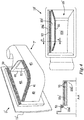
Figure 4 , in which first and second side sealings 39, 41 are adapted to seal in the lateral direction between a filling unit 7' and a housing 19'. Afirst side wall 43 of the filling unit 7' is attached to the hatch 13'. The second, third andfourth side walls fourth side wall 49 of the filling unit 7' has anopening 51 for leading the washer fluid to theconduit 11. In this embodiment, there is no horizontal upper wall portion 10 like in the embodiment ofFigure 2 . Instead theside walls Figure 2 . - The
first side wall 43 located at the hatch 13' protrudes above theother side walls first side wall 43, such that the first side sealing 39 is located above theother side walls - An outside of the
side walls vehicle 1. The side wall 23'of the housing thus has a stepwise configuration, with anupper portion 23a' providing a seat for the first wall sealing 53 and a lower portion 23b' providing a seat for the second wall sealing 55 and astep portion 23c' therebetween. Thestep portion 23c' will act as a cover for the aperture of the filling unit 7' in the inactive position. The configuration of thestep portion 23c', e.g. its inclination is selected to correspond to that of the filling unit 7' in order to provide the desired sealing of the filling unit 7' in the inactive position. - The side and wall sealings 39, 41, 53, 55, together with the part of
step portion 23c' of the side wall 23' being located above for the aperture of the filling unit 7', help to prevent that washer fluid is splashed during driving on e.g. a bumpy road. Preferably, the first side sealing 39 and the second side sealing 41 of the filling unit 7' are being integrated into the filling unit 7', when manufacturing it e.g. by means of two-component moulding. Correspondingly, preferably the first wall sealing 53 and the second wall sealing 55 are being integrated into the housing 19' when manufacturing the housing 19', e.g. by means of two-component moulding. It would also be feasible to only use sealings in either the side wall of the filling unit 7' or in the side wall 23' of the housing 19'. -
Figure 5a illustrates yet another embodiment of thewasher fluid system 3", in which theconduit 11" is flexible, since a portion of it has a flexible wall, illustrated as a tube with an expandable corrugated wall. Thehatch 13" is hingedly connected to the vehicle body, e.g. to the housing. The filling unit 7" is attached to thehatch 13". Due to the flexibility of theconduit 11", the filling unit 7" is displaced together with thehatch 13", when thehatch 13" is transited to the open position. During this displacement to the fill position of the filling unit 7", theconduit 11" is being curved to follow the displacement of thehatch 13". Further, the length of theconduit 11" may be increased during the displacement by means of the expandable corrugated wall. The flexible portion of theconduit 11" may be curved by at least 90 degrees or at least 135 degrees, e.g. depending on how far thehatch 13" is pivoted. - In the illustrated embodiment, the filling unit 7" comprises a
cover 57 to prevent any splash, but it would also be possible to seal the filling unit 7" of this embodiment with any of thesealings Figures 2 and4 . -
Figure 5b illustrates a further embodiment of the washer fluid system. Thehatch 13b" is hingedly connected to the vehicle body, e.g. to the housing. The fillingunit 7b" is movably attached to thehatch 13b" by means of guides, illustrated asrails hatch 13b" and corresponding protruding members, illustrated aspins pins respective rail unit 7b" is displaced together with thehatch 13", when thehatch 13" is transited to the open position. Thepin head 63a with a larger diameter than astem 65a. Therail head 63a fits in therail head 63a is able to slide along therail head 63a has a large enough diameter no to come out through therail conduit 11 b" may flexible in a similar way as for the embodiment ofFigure 5a , e.g. by having an expandable corrugated wall. The length of theconduit 11b" may be increased during the displacement by means of the expandable corrugated wall. Theguides more rails pins -
Figure 6 shows an alternative hinge for the filling unit 7"' in an alternativewasher fluid system 3"'. Apivot pin 67 is utilized as a pivot axis for the filling unit 7"'. Thepivot pin 67 is rotatably attached to thehousing 19"' and goes through the tubular structure 31'" of the filling unit 7"'. At a bottom of the tubular structure 31'", there aredrainage holes 69, through which the washer fluid can pass when being filled. Thebottom wall 25"' of thehousing 19"' also comprises drainage holes 71, through which the washer fluid can pass when being filled. The washer fluid thereafter flows onwards through theconduit 11"' to thereservoir 5. - Further modifications of the invention within the scope of the appended claims are feasible. As such, the present invention should not be considered as limited by the embodiments and figures described herein. Rather, the full scope of the invention should be determined by the appended claims, with reference to the description and drawings.
Claims (15)
- A washer fluid system (3, 3', 3", 3"') for a vehicle (1), said washer fluid system (3, 3', 3", 3"') comprising- a reservoir (5), adapted to contain washer fluid,- a filling unit (7, 7', 7", 7"') comprising an aperture (9) for filling washer fluid into said reservoir (5),- a conduit (11,11", 11'") providing a fluid connection from said filling unit (7, 7', 7", 7"') to said reservoir (5),said filling unit (7, 7', 7", 7"') being transitable between an inactive position and a fill position,
characterized in that
said washer fluid system (3, 3', 3", 3"') further comprises a hatch (13, 13', 13") being transitable between a closed position and an open position,
said filling unit (7, 7', 7", 7"') being attached to, or integrated with, said hatch (13, 13', 13"), such that said filling unit (7, 7', 7", 7"') is displaced together with said hatch (13, 13', 13") when transiting from said closed position to said open position, said filling unit (7, 7', 7", 7"') thereby transiting from said inactive position to said fill position. - The washer fluid system (3, 3', 3", 3"') according to claim 1, wherein said hatch (13, 13', 13") is configured to form a part of a body of said vehicle (1), e.g. a part of a fender (15), door or bonnet of said vehicle (1).
- The washer fluid system (3, 3', 3", 3"') according to claim 1 or 2, wherein said hatch (13, 13', 13") is transitable between said closed position and said open position by means of a displacement comprising a pivotal displacement around a pivot arm (31, 35, 67), said pivot arm (31, 35, 67) preferably being comprised in or constituting a part of said filling unit (7, 7', 7", 7"').
- The washer fluid system (3, 3', 3'") according to any one of the preceding claims, wherein said filling unit (7, 7', 7"') comprises a tubular structure (31, 31'"), adapted to extend in a vertical direction to connect to said conduit (11, 11'").
- The washer fluid system (3, 3"') according to claims 3 and 4, wherein said tubular structure (31, 31'") constitutes said pivot arm or is located around said pivot arm.
- The washer fluid system (3") according to any one of the preceding claims,
wherein said conduit (11 "), or at least a portion of said conduit (11 "), is flexible, e.g. by being curvable and/or by having a variable length. - The washer fluid system (3, 3', 3", 3"') according to any one of the preceding claims, wherein said washer fluid system (3, 3', 3", 3"') comprises a housing (19, 19'") adapted to contain said filling unit (7, 7', 7", 7"') when in said inactive position, said housing (19, 19'") having an opening (27), through which said filling unit (7, 7', 7", 7"') is transitable to said fill position, said hatch (13, 13', 13") in said closed position being adapted to cover said opening (27) of said housing (19, 19"').
- The washer fluid system (3) according to claim 7, wherein said housing (19) comprises a ceiling (21) adapted to form a cover of said aperture (9) of said filling unit (7), when said filling unit (7) is in said inactive position.
- The washer fluid system (3) according to claim 8, wherein a side wall of said filling unit (7) comprises an upper wall portion (10) being substantially horizontal and said ceiling (21) comprises a top sealing (33) adapted to seal between said ceiling (21) and said upper wall portion (10) of said filling unit (7) around at least a portion of a circumference of said aperture (9) of said filling unit (7).
- The washer fluid system (3') according to any one of claims 7-9, wherein a side wall (43, 45, 47, 49) of said filling unit (7') comprises a side sealing (39, 41) adapted to seal between said filling unit (7') and a side wall (23') of said housing (19').
- The washer fluid system (3') according to claim 10, wherein said side sealing (39, 41) of said filling unit (7') is integrated in said filling unit (7'), e.g. by two-component injection moulding.
- The washer fluid system (3') according to any one of claims 7-11, wherein said side wall (23') of said housing comprises a wall sealing (53, 55) adapted to seal between said filling unit (7') and said side wall (23') of said housing.
- The washer fluid system (3, 3') according to claim 9 and/or 12, wherein said top sealing (33) and/or said wall sealing (53, 55) of said housing (19, 19') is integrated in said housing (19, 19'), e.g. by two-component injection moulding.
- The washer fluid system (3"') according to any one of claims 7-13, wherein a bottom wall (25"') of said housing (19"') comprises at least one drainage hole (71) providing a fluid connection from said filling unit (7"') to said conduit (11'").
- The washer fluid system according to any one of the preceding claims, wherein said hatch (13b") comprises at least one guide (59a, 59b) adapted to cooperate with a protruding member (61 a, 61 b) comprised in said filling unit (7b").
Priority Applications (1)
| Application Number | Priority Date | Filing Date | Title |
|---|---|---|---|
| EP17167377.5A EP3392099B1 (en) | 2017-04-20 | 2017-04-20 | Washer fluid system |
Applications Claiming Priority (1)
| Application Number | Priority Date | Filing Date | Title |
|---|---|---|---|
| EP17167377.5A EP3392099B1 (en) | 2017-04-20 | 2017-04-20 | Washer fluid system |
Publications (2)
| Publication Number | Publication Date |
|---|---|
| EP3392099A1 true EP3392099A1 (en) | 2018-10-24 |
| EP3392099B1 EP3392099B1 (en) | 2020-11-25 |
Family
ID=58579106
Family Applications (1)
| Application Number | Title | Priority Date | Filing Date |
|---|---|---|---|
| EP17167377.5A Active EP3392099B1 (en) | 2017-04-20 | 2017-04-20 | Washer fluid system |
Country Status (1)
| Country | Link |
|---|---|
| EP (1) | EP3392099B1 (en) |
Cited By (6)
| Publication number | Priority date | Publication date | Assignee | Title |
|---|---|---|---|---|
| US20230331192A1 (en) * | 2022-04-15 | 2023-10-19 | Illinois Tool Works Inc. | Filling Device for Replenishing Wiper Water of Vehicle |
| FR3141121A1 (en) * | 2022-10-19 | 2024-04-26 | Valeo Systèmes D’Essuyage | Device for dispensing cleaning fluid for the windshield of a motor vehicle, and motor vehicle comprising such a device |
| FR3143502A1 (en) * | 2022-12-20 | 2024-06-21 | Valeo Systèmes D’Essuyage | Device for dispensing cleaning fluid for the windshield of a motor vehicle, and motor vehicle comprising such a device |
| DE102023115381A1 (en) * | 2023-06-13 | 2024-12-19 | Ford Global Technologies, Llc | Filling device for an operating fluid of a vehicle on a drawer |
| DE102023123266A1 (en) * | 2023-08-30 | 2025-03-06 | Ford Global Technologies Llc | front service panel with integrated washer fluid tank |
| DE102023135273A1 (en) * | 2023-12-15 | 2025-06-18 | Audi Aktiengesellschaft | Carrier component for mounting in the outer shell of a vehicle and vehicle comprising the carrier component |
Citations (2)
| Publication number | Priority date | Publication date | Assignee | Title |
|---|---|---|---|---|
| DE102015204791A1 (en) | 2014-03-24 | 2015-09-24 | Ford Global Technologies, Llc | Windscreen washer system for motor vehicles |
| DE202016106334U1 (en) * | 2015-11-16 | 2017-02-09 | Ford Global Technologies, Llc | Front grill emblem for unlocking a hood and filling a windscreen washer fluid container of a motor vehicle |
-
2017
- 2017-04-20 EP EP17167377.5A patent/EP3392099B1/en active Active
Patent Citations (2)
| Publication number | Priority date | Publication date | Assignee | Title |
|---|---|---|---|---|
| DE102015204791A1 (en) | 2014-03-24 | 2015-09-24 | Ford Global Technologies, Llc | Windscreen washer system for motor vehicles |
| DE202016106334U1 (en) * | 2015-11-16 | 2017-02-09 | Ford Global Technologies, Llc | Front grill emblem for unlocking a hood and filling a windscreen washer fluid container of a motor vehicle |
Cited By (8)
| Publication number | Priority date | Publication date | Assignee | Title |
|---|---|---|---|---|
| US20230331192A1 (en) * | 2022-04-15 | 2023-10-19 | Illinois Tool Works Inc. | Filling Device for Replenishing Wiper Water of Vehicle |
| US12503080B2 (en) * | 2022-04-15 | 2025-12-23 | Illinois Tool Works Inc. | Filling device for replenishing wiper water of vehicle |
| FR3141121A1 (en) * | 2022-10-19 | 2024-04-26 | Valeo Systèmes D’Essuyage | Device for dispensing cleaning fluid for the windshield of a motor vehicle, and motor vehicle comprising such a device |
| FR3143502A1 (en) * | 2022-12-20 | 2024-06-21 | Valeo Systèmes D’Essuyage | Device for dispensing cleaning fluid for the windshield of a motor vehicle, and motor vehicle comprising such a device |
| DE102023115381A1 (en) * | 2023-06-13 | 2024-12-19 | Ford Global Technologies, Llc | Filling device for an operating fluid of a vehicle on a drawer |
| DE102023123266A1 (en) * | 2023-08-30 | 2025-03-06 | Ford Global Technologies Llc | front service panel with integrated washer fluid tank |
| DE102023135273A1 (en) * | 2023-12-15 | 2025-06-18 | Audi Aktiengesellschaft | Carrier component for mounting in the outer shell of a vehicle and vehicle comprising the carrier component |
| DE102023135273B4 (en) * | 2023-12-15 | 2025-10-23 | Audi Aktiengesellschaft | Carrier component for mounting in the outer shell of a vehicle and vehicle comprising the carrier component |
Also Published As
| Publication number | Publication date |
|---|---|
| EP3392099B1 (en) | 2020-11-25 |
Similar Documents
| Publication | Publication Date | Title |
|---|---|---|
| EP3392099B1 (en) | Washer fluid system | |
| JP4464034B2 (en) | Headlamp cleaning device | |
| US8162375B2 (en) | Hinge mounted fuel housing seal | |
| US20170001517A1 (en) | Closure device for a filling or connection opening on a vehicle | |
| US9963120B2 (en) | Vehicular washer nozzle device mount structure | |
| US10589683B2 (en) | Trapped cutline gasket for external side mirror | |
| US11535198B2 (en) | Filling apparatus for a vehicle, and vehicle having such a filling apparatus | |
| US9586517B2 (en) | Exterior mirror for a motor vehicle with liquid container refill funnel | |
| US5299616A (en) | Screen for use with a vehicle window | |
| JP7230310B2 (en) | Visual recognition device for vehicles | |
| CN1990308B (en) | Blind member for vehicle, and gap-closing structure including blind member | |
| US20060244288A1 (en) | System for refilling a fluid reservoir | |
| EP1057703B1 (en) | A filler arrangement | |
| GB2566302A (en) | A finisher assembly for a vehicle | |
| US8714615B2 (en) | Motor vehicle interior structure having a door with impeded movement, and dashboard and motor vehicle equipped with the same | |
| JP2024017261A (en) | tailgate structure | |
| CN108657128A (en) | Windscreen wiper arm and cap for autonomous vehicle | |
| JP4313291B2 (en) | Water drainage structure for vehicle wind glass | |
| JP4917843B2 (en) | Drain hose connection structure | |
| WO2006045908A1 (en) | Vehicle with a convertible roof and a hatchback | |
| JP5151187B2 (en) | Wiper pivot device | |
| US12415481B2 (en) | Fascia door and washer fluid reservoir | |
| JP2006240561A (en) | Washer nozzle arrangement structure | |
| EP1544010B1 (en) | Vehicle having a rotatable windshield panel | |
| KR100508187B1 (en) | Filling apparatus of fuel tank |
Legal Events
| Date | Code | Title | Description |
|---|---|---|---|
| PUAI | Public reference made under article 153(3) epc to a published international application that has entered the european phase |
Free format text: ORIGINAL CODE: 0009012 |
|
| STAA | Information on the status of an ep patent application or granted ep patent |
Free format text: STATUS: THE APPLICATION HAS BEEN PUBLISHED |
|
| AK | Designated contracting states |
Kind code of ref document: A1 Designated state(s): AL AT BE BG CH CY CZ DE DK EE ES FI FR GB GR HR HU IE IS IT LI LT LU LV MC MK MT NL NO PL PT RO RS SE SI SK SM TR |
|
| AX | Request for extension of the european patent |
Extension state: BA ME |
|
| STAA | Information on the status of an ep patent application or granted ep patent |
Free format text: STATUS: REQUEST FOR EXAMINATION WAS MADE |
|
| 17P | Request for examination filed |
Effective date: 20190503 |
|
| RBV | Designated contracting states (corrected) |
Designated state(s): AL AT BE BG CH CY CZ DE DK EE ES FI FR GB GR HR HU IE IS IT LI LT LU LV MC MK MT NL NO PL PT RO RS SE SI SK SM TR |
|
| STAA | Information on the status of an ep patent application or granted ep patent |
Free format text: STATUS: EXAMINATION IS IN PROGRESS |
|
| 17Q | First examination report despatched |
Effective date: 20200117 |
|
| GRAP | Despatch of communication of intention to grant a patent |
Free format text: ORIGINAL CODE: EPIDOSNIGR1 |
|
| STAA | Information on the status of an ep patent application or granted ep patent |
Free format text: STATUS: GRANT OF PATENT IS INTENDED |
|
| INTG | Intention to grant announced |
Effective date: 20200706 |
|
| GRAS | Grant fee paid |
Free format text: ORIGINAL CODE: EPIDOSNIGR3 |
|
| GRAA | (expected) grant |
Free format text: ORIGINAL CODE: 0009210 |
|
| STAA | Information on the status of an ep patent application or granted ep patent |
Free format text: STATUS: THE PATENT HAS BEEN GRANTED |
|
| AK | Designated contracting states |
Kind code of ref document: B1 Designated state(s): AL AT BE BG CH CY CZ DE DK EE ES FI FR GB GR HR HU IE IS IT LI LT LU LV MC MK MT NL NO PL PT RO RS SE SI SK SM TR |
|
| REG | Reference to a national code |
Ref country code: GB Ref legal event code: FG4D |
|
| REG | Reference to a national code |
Ref country code: CH Ref legal event code: EP |
|
| REG | Reference to a national code |
Ref country code: AT Ref legal event code: REF Ref document number: 1337930 Country of ref document: AT Kind code of ref document: T Effective date: 20201215 |
|
| REG | Reference to a national code |
Ref country code: DE Ref legal event code: R096 Ref document number: 602017028082 Country of ref document: DE |
|
| REG | Reference to a national code |
Ref country code: IE Ref legal event code: FG4D |
|
| REG | Reference to a national code |
Ref country code: AT Ref legal event code: MK05 Ref document number: 1337930 Country of ref document: AT Kind code of ref document: T Effective date: 20201125 |
|
| REG | Reference to a national code |
Ref country code: NL Ref legal event code: MP Effective date: 20201125 |
|
| PG25 | Lapsed in a contracting state [announced via postgrant information from national office to epo] |
Ref country code: GR Free format text: LAPSE BECAUSE OF FAILURE TO SUBMIT A TRANSLATION OF THE DESCRIPTION OR TO PAY THE FEE WITHIN THE PRESCRIBED TIME-LIMIT Effective date: 20210226 Ref country code: FI Free format text: LAPSE BECAUSE OF FAILURE TO SUBMIT A TRANSLATION OF THE DESCRIPTION OR TO PAY THE FEE WITHIN THE PRESCRIBED TIME-LIMIT Effective date: 20201125 Ref country code: RS Free format text: LAPSE BECAUSE OF FAILURE TO SUBMIT A TRANSLATION OF THE DESCRIPTION OR TO PAY THE FEE WITHIN THE PRESCRIBED TIME-LIMIT Effective date: 20201125 Ref country code: PT Free format text: LAPSE BECAUSE OF FAILURE TO SUBMIT A TRANSLATION OF THE DESCRIPTION OR TO PAY THE FEE WITHIN THE PRESCRIBED TIME-LIMIT Effective date: 20210325 Ref country code: NO Free format text: LAPSE BECAUSE OF FAILURE TO SUBMIT A TRANSLATION OF THE DESCRIPTION OR TO PAY THE FEE WITHIN THE PRESCRIBED TIME-LIMIT Effective date: 20210225 |
|
| PG25 | Lapsed in a contracting state [announced via postgrant information from national office to epo] |
Ref country code: SE Free format text: LAPSE BECAUSE OF FAILURE TO SUBMIT A TRANSLATION OF THE DESCRIPTION OR TO PAY THE FEE WITHIN THE PRESCRIBED TIME-LIMIT Effective date: 20201125 Ref country code: AT Free format text: LAPSE BECAUSE OF FAILURE TO SUBMIT A TRANSLATION OF THE DESCRIPTION OR TO PAY THE FEE WITHIN THE PRESCRIBED TIME-LIMIT Effective date: 20201125 Ref country code: BG Free format text: LAPSE BECAUSE OF FAILURE TO SUBMIT A TRANSLATION OF THE DESCRIPTION OR TO PAY THE FEE WITHIN THE PRESCRIBED TIME-LIMIT Effective date: 20210225 Ref country code: PL Free format text: LAPSE BECAUSE OF FAILURE TO SUBMIT A TRANSLATION OF THE DESCRIPTION OR TO PAY THE FEE WITHIN THE PRESCRIBED TIME-LIMIT Effective date: 20201125 Ref country code: LV Free format text: LAPSE BECAUSE OF FAILURE TO SUBMIT A TRANSLATION OF THE DESCRIPTION OR TO PAY THE FEE WITHIN THE PRESCRIBED TIME-LIMIT Effective date: 20201125 Ref country code: IS Free format text: LAPSE BECAUSE OF FAILURE TO SUBMIT A TRANSLATION OF THE DESCRIPTION OR TO PAY THE FEE WITHIN THE PRESCRIBED TIME-LIMIT Effective date: 20210325 |
|
| REG | Reference to a national code |
Ref country code: LT Ref legal event code: MG9D |
|
| PG25 | Lapsed in a contracting state [announced via postgrant information from national office to epo] |
Ref country code: HR Free format text: LAPSE BECAUSE OF FAILURE TO SUBMIT A TRANSLATION OF THE DESCRIPTION OR TO PAY THE FEE WITHIN THE PRESCRIBED TIME-LIMIT Effective date: 20201125 |
|
| PG25 | Lapsed in a contracting state [announced via postgrant information from national office to epo] |
Ref country code: CZ Free format text: LAPSE BECAUSE OF FAILURE TO SUBMIT A TRANSLATION OF THE DESCRIPTION OR TO PAY THE FEE WITHIN THE PRESCRIBED TIME-LIMIT Effective date: 20201125 Ref country code: EE Free format text: LAPSE BECAUSE OF FAILURE TO SUBMIT A TRANSLATION OF THE DESCRIPTION OR TO PAY THE FEE WITHIN THE PRESCRIBED TIME-LIMIT Effective date: 20201125 Ref country code: LT Free format text: LAPSE BECAUSE OF FAILURE TO SUBMIT A TRANSLATION OF THE DESCRIPTION OR TO PAY THE FEE WITHIN THE PRESCRIBED TIME-LIMIT Effective date: 20201125 Ref country code: SM Free format text: LAPSE BECAUSE OF FAILURE TO SUBMIT A TRANSLATION OF THE DESCRIPTION OR TO PAY THE FEE WITHIN THE PRESCRIBED TIME-LIMIT Effective date: 20201125 Ref country code: SK Free format text: LAPSE BECAUSE OF FAILURE TO SUBMIT A TRANSLATION OF THE DESCRIPTION OR TO PAY THE FEE WITHIN THE PRESCRIBED TIME-LIMIT Effective date: 20201125 Ref country code: RO Free format text: LAPSE BECAUSE OF FAILURE TO SUBMIT A TRANSLATION OF THE DESCRIPTION OR TO PAY THE FEE WITHIN THE PRESCRIBED TIME-LIMIT Effective date: 20201125 |
|
| REG | Reference to a national code |
Ref country code: DE Ref legal event code: R097 Ref document number: 602017028082 Country of ref document: DE |
|
| PG25 | Lapsed in a contracting state [announced via postgrant information from national office to epo] |
Ref country code: DK Free format text: LAPSE BECAUSE OF FAILURE TO SUBMIT A TRANSLATION OF THE DESCRIPTION OR TO PAY THE FEE WITHIN THE PRESCRIBED TIME-LIMIT Effective date: 20201125 |
|
| PLBE | No opposition filed within time limit |
Free format text: ORIGINAL CODE: 0009261 |
|
| STAA | Information on the status of an ep patent application or granted ep patent |
Free format text: STATUS: NO OPPOSITION FILED WITHIN TIME LIMIT |
|
| PG25 | Lapsed in a contracting state [announced via postgrant information from national office to epo] |
Ref country code: NL Free format text: LAPSE BECAUSE OF FAILURE TO SUBMIT A TRANSLATION OF THE DESCRIPTION OR TO PAY THE FEE WITHIN THE PRESCRIBED TIME-LIMIT Effective date: 20201125 Ref country code: AL Free format text: LAPSE BECAUSE OF FAILURE TO SUBMIT A TRANSLATION OF THE DESCRIPTION OR TO PAY THE FEE WITHIN THE PRESCRIBED TIME-LIMIT Effective date: 20201125 |
|
| 26N | No opposition filed |
Effective date: 20210826 |
|
| PG25 | Lapsed in a contracting state [announced via postgrant information from national office to epo] |
Ref country code: MC Free format text: LAPSE BECAUSE OF FAILURE TO SUBMIT A TRANSLATION OF THE DESCRIPTION OR TO PAY THE FEE WITHIN THE PRESCRIBED TIME-LIMIT Effective date: 20201125 Ref country code: SI Free format text: LAPSE BECAUSE OF FAILURE TO SUBMIT A TRANSLATION OF THE DESCRIPTION OR TO PAY THE FEE WITHIN THE PRESCRIBED TIME-LIMIT Effective date: 20201125 |
|
| GBPC | Gb: european patent ceased through non-payment of renewal fee |
Effective date: 20210420 |
|
| PG25 | Lapsed in a contracting state [announced via postgrant information from national office to epo] |
Ref country code: LU Free format text: LAPSE BECAUSE OF NON-PAYMENT OF DUE FEES Effective date: 20210420 |
|
| REG | Reference to a national code |
Ref country code: BE Ref legal event code: MM Effective date: 20210430 |
|
| PG25 | Lapsed in a contracting state [announced via postgrant information from national office to epo] |
Ref country code: LI Free format text: LAPSE BECAUSE OF NON-PAYMENT OF DUE FEES Effective date: 20210430 Ref country code: CH Free format text: LAPSE BECAUSE OF NON-PAYMENT OF DUE FEES Effective date: 20210430 Ref country code: ES Free format text: LAPSE BECAUSE OF FAILURE TO SUBMIT A TRANSLATION OF THE DESCRIPTION OR TO PAY THE FEE WITHIN THE PRESCRIBED TIME-LIMIT Effective date: 20201125 Ref country code: GB Free format text: LAPSE BECAUSE OF NON-PAYMENT OF DUE FEES Effective date: 20210420 |
|
| PG25 | Lapsed in a contracting state [announced via postgrant information from national office to epo] |
Ref country code: IE Free format text: LAPSE BECAUSE OF NON-PAYMENT OF DUE FEES Effective date: 20210420 |
|
| PG25 | Lapsed in a contracting state [announced via postgrant information from national office to epo] |
Ref country code: IS Free format text: LAPSE BECAUSE OF FAILURE TO SUBMIT A TRANSLATION OF THE DESCRIPTION OR TO PAY THE FEE WITHIN THE PRESCRIBED TIME-LIMIT Effective date: 20210325 |
|
| PG25 | Lapsed in a contracting state [announced via postgrant information from national office to epo] |
Ref country code: BE Free format text: LAPSE BECAUSE OF NON-PAYMENT OF DUE FEES Effective date: 20210430 |
|
| PG25 | Lapsed in a contracting state [announced via postgrant information from national office to epo] |
Ref country code: CY Free format text: LAPSE BECAUSE OF FAILURE TO SUBMIT A TRANSLATION OF THE DESCRIPTION OR TO PAY THE FEE WITHIN THE PRESCRIBED TIME-LIMIT Effective date: 20201125 |
|
| PG25 | Lapsed in a contracting state [announced via postgrant information from national office to epo] |
Ref country code: HU Free format text: LAPSE BECAUSE OF FAILURE TO SUBMIT A TRANSLATION OF THE DESCRIPTION OR TO PAY THE FEE WITHIN THE PRESCRIBED TIME-LIMIT; INVALID AB INITIO Effective date: 20170420 |
|
| P01 | Opt-out of the competence of the unified patent court (upc) registered |
Effective date: 20231212 |
|
| PG25 | Lapsed in a contracting state [announced via postgrant information from national office to epo] |
Ref country code: MK Free format text: LAPSE BECAUSE OF FAILURE TO SUBMIT A TRANSLATION OF THE DESCRIPTION OR TO PAY THE FEE WITHIN THE PRESCRIBED TIME-LIMIT Effective date: 20201125 |
|
| PG25 | Lapsed in a contracting state [announced via postgrant information from national office to epo] |
Ref country code: TR Free format text: LAPSE BECAUSE OF FAILURE TO SUBMIT A TRANSLATION OF THE DESCRIPTION OR TO PAY THE FEE WITHIN THE PRESCRIBED TIME-LIMIT Effective date: 20201125 |
|
| PG25 | Lapsed in a contracting state [announced via postgrant information from national office to epo] |
Ref country code: MT Free format text: LAPSE BECAUSE OF FAILURE TO SUBMIT A TRANSLATION OF THE DESCRIPTION OR TO PAY THE FEE WITHIN THE PRESCRIBED TIME-LIMIT Effective date: 20201125 |
|
| PGFP | Annual fee paid to national office [announced via postgrant information from national office to epo] |
Ref country code: IT Payment date: 20250319 Year of fee payment: 9 |
|
| PGFP | Annual fee paid to national office [announced via postgrant information from national office to epo] |
Ref country code: DE Payment date: 20250319 Year of fee payment: 9 |
|
| PGFP | Annual fee paid to national office [announced via postgrant information from national office to epo] |
Ref country code: FR Payment date: 20260319 Year of fee payment: 10 |