EP3392071A1 - Four-wheel drive hybrid vehicle - Google Patents
Four-wheel drive hybrid vehicle Download PDFInfo
- Publication number
- EP3392071A1 EP3392071A1 EP18168593.4A EP18168593A EP3392071A1 EP 3392071 A1 EP3392071 A1 EP 3392071A1 EP 18168593 A EP18168593 A EP 18168593A EP 3392071 A1 EP3392071 A1 EP 3392071A1
- Authority
- EP
- European Patent Office
- Prior art keywords
- motor
- propeller shaft
- engine
- transmission
- pair
- Prior art date
- Legal status (The legal status is an assumption and is not a legal conclusion. Google has not performed a legal analysis and makes no representation as to the accuracy of the status listed.)
- Granted
Links
Images


Classifications
-
- B—PERFORMING OPERATIONS; TRANSPORTING
- B60—VEHICLES IN GENERAL
- B60K—ARRANGEMENT OR MOUNTING OF PROPULSION UNITS OR OF TRANSMISSIONS IN VEHICLES; ARRANGEMENT OR MOUNTING OF PLURAL DIVERSE PRIME-MOVERS IN VEHICLES; AUXILIARY DRIVES FOR VEHICLES; INSTRUMENTATION OR DASHBOARDS FOR VEHICLES; ARRANGEMENTS IN CONNECTION WITH COOLING, AIR INTAKE, GAS EXHAUST OR FUEL SUPPLY OF PROPULSION UNITS IN VEHICLES
- B60K6/00—Arrangement or mounting of plural diverse prime-movers for mutual or common propulsion, e.g. hybrid propulsion systems comprising electric motors and internal combustion engines
- B60K6/20—Arrangement or mounting of plural diverse prime-movers for mutual or common propulsion, e.g. hybrid propulsion systems comprising electric motors and internal combustion engines the prime-movers consisting of electric motors and internal combustion engines, e.g. HEVs
- B60K6/50—Architecture of the driveline characterised by arrangement or kind of transmission units
- B60K6/52—Driving a plurality of drive axles, e.g. four-wheel drive
-
- B—PERFORMING OPERATIONS; TRANSPORTING
- B60—VEHICLES IN GENERAL
- B60K—ARRANGEMENT OR MOUNTING OF PROPULSION UNITS OR OF TRANSMISSIONS IN VEHICLES; ARRANGEMENT OR MOUNTING OF PLURAL DIVERSE PRIME-MOVERS IN VEHICLES; AUXILIARY DRIVES FOR VEHICLES; INSTRUMENTATION OR DASHBOARDS FOR VEHICLES; ARRANGEMENTS IN CONNECTION WITH COOLING, AIR INTAKE, GAS EXHAUST OR FUEL SUPPLY OF PROPULSION UNITS IN VEHICLES
- B60K17/00—Arrangement or mounting of transmissions in vehicles
- B60K17/34—Arrangement or mounting of transmissions in vehicles for driving both front and rear wheels, e.g. four wheel drive vehicles
-
- B—PERFORMING OPERATIONS; TRANSPORTING
- B60—VEHICLES IN GENERAL
- B60K—ARRANGEMENT OR MOUNTING OF PROPULSION UNITS OR OF TRANSMISSIONS IN VEHICLES; ARRANGEMENT OR MOUNTING OF PLURAL DIVERSE PRIME-MOVERS IN VEHICLES; AUXILIARY DRIVES FOR VEHICLES; INSTRUMENTATION OR DASHBOARDS FOR VEHICLES; ARRANGEMENTS IN CONNECTION WITH COOLING, AIR INTAKE, GAS EXHAUST OR FUEL SUPPLY OF PROPULSION UNITS IN VEHICLES
- B60K6/00—Arrangement or mounting of plural diverse prime-movers for mutual or common propulsion, e.g. hybrid propulsion systems comprising electric motors and internal combustion engines
- B60K6/20—Arrangement or mounting of plural diverse prime-movers for mutual or common propulsion, e.g. hybrid propulsion systems comprising electric motors and internal combustion engines the prime-movers consisting of electric motors and internal combustion engines, e.g. HEVs
- B60K6/22—Arrangement or mounting of plural diverse prime-movers for mutual or common propulsion, e.g. hybrid propulsion systems comprising electric motors and internal combustion engines the prime-movers consisting of electric motors and internal combustion engines, e.g. HEVs characterised by apparatus, components or means specially adapted for HEVs
- B60K6/40—Arrangement or mounting of plural diverse prime-movers for mutual or common propulsion, e.g. hybrid propulsion systems comprising electric motors and internal combustion engines the prime-movers consisting of electric motors and internal combustion engines, e.g. HEVs characterised by apparatus, components or means specially adapted for HEVs characterised by the assembly or relative disposition of components
-
- B—PERFORMING OPERATIONS; TRANSPORTING
- B60—VEHICLES IN GENERAL
- B60K—ARRANGEMENT OR MOUNTING OF PROPULSION UNITS OR OF TRANSMISSIONS IN VEHICLES; ARRANGEMENT OR MOUNTING OF PLURAL DIVERSE PRIME-MOVERS IN VEHICLES; AUXILIARY DRIVES FOR VEHICLES; INSTRUMENTATION OR DASHBOARDS FOR VEHICLES; ARRANGEMENTS IN CONNECTION WITH COOLING, AIR INTAKE, GAS EXHAUST OR FUEL SUPPLY OF PROPULSION UNITS IN VEHICLES
- B60K17/00—Arrangement or mounting of transmissions in vehicles
- B60K17/22—Arrangement or mounting of transmissions in vehicles characterised by arrangement, location, or type of main drive shafting, e.g. cardan shaft
-
- B—PERFORMING OPERATIONS; TRANSPORTING
- B60—VEHICLES IN GENERAL
- B60K—ARRANGEMENT OR MOUNTING OF PROPULSION UNITS OR OF TRANSMISSIONS IN VEHICLES; ARRANGEMENT OR MOUNTING OF PLURAL DIVERSE PRIME-MOVERS IN VEHICLES; AUXILIARY DRIVES FOR VEHICLES; INSTRUMENTATION OR DASHBOARDS FOR VEHICLES; ARRANGEMENTS IN CONNECTION WITH COOLING, AIR INTAKE, GAS EXHAUST OR FUEL SUPPLY OF PROPULSION UNITS IN VEHICLES
- B60K17/00—Arrangement or mounting of transmissions in vehicles
- B60K17/34—Arrangement or mounting of transmissions in vehicles for driving both front and rear wheels, e.g. four wheel drive vehicles
- B60K17/344—Arrangement or mounting of transmissions in vehicles for driving both front and rear wheels, e.g. four wheel drive vehicles having a transfer gear
- B60K17/346—Arrangement or mounting of transmissions in vehicles for driving both front and rear wheels, e.g. four wheel drive vehicles having a transfer gear the transfer gear being a differential gear
- B60K17/3462—Arrangement or mounting of transmissions in vehicles for driving both front and rear wheels, e.g. four wheel drive vehicles having a transfer gear the transfer gear being a differential gear with means for changing distribution of torque between front and rear wheels
-
- B—PERFORMING OPERATIONS; TRANSPORTING
- B60—VEHICLES IN GENERAL
- B60K—ARRANGEMENT OR MOUNTING OF PROPULSION UNITS OR OF TRANSMISSIONS IN VEHICLES; ARRANGEMENT OR MOUNTING OF PLURAL DIVERSE PRIME-MOVERS IN VEHICLES; AUXILIARY DRIVES FOR VEHICLES; INSTRUMENTATION OR DASHBOARDS FOR VEHICLES; ARRANGEMENTS IN CONNECTION WITH COOLING, AIR INTAKE, GAS EXHAUST OR FUEL SUPPLY OF PROPULSION UNITS IN VEHICLES
- B60K17/00—Arrangement or mounting of transmissions in vehicles
- B60K17/34—Arrangement or mounting of transmissions in vehicles for driving both front and rear wheels, e.g. four wheel drive vehicles
- B60K17/356—Arrangement or mounting of transmissions in vehicles for driving both front and rear wheels, e.g. four wheel drive vehicles having fluid or electric motor, for driving one or more wheels
-
- B—PERFORMING OPERATIONS; TRANSPORTING
- B60—VEHICLES IN GENERAL
- B60K—ARRANGEMENT OR MOUNTING OF PROPULSION UNITS OR OF TRANSMISSIONS IN VEHICLES; ARRANGEMENT OR MOUNTING OF PLURAL DIVERSE PRIME-MOVERS IN VEHICLES; AUXILIARY DRIVES FOR VEHICLES; INSTRUMENTATION OR DASHBOARDS FOR VEHICLES; ARRANGEMENTS IN CONNECTION WITH COOLING, AIR INTAKE, GAS EXHAUST OR FUEL SUPPLY OF PROPULSION UNITS IN VEHICLES
- B60K6/00—Arrangement or mounting of plural diverse prime-movers for mutual or common propulsion, e.g. hybrid propulsion systems comprising electric motors and internal combustion engines
- B60K6/20—Arrangement or mounting of plural diverse prime-movers for mutual or common propulsion, e.g. hybrid propulsion systems comprising electric motors and internal combustion engines the prime-movers consisting of electric motors and internal combustion engines, e.g. HEVs
- B60K6/22—Arrangement or mounting of plural diverse prime-movers for mutual or common propulsion, e.g. hybrid propulsion systems comprising electric motors and internal combustion engines the prime-movers consisting of electric motors and internal combustion engines, e.g. HEVs characterised by apparatus, components or means specially adapted for HEVs
- B60K6/24—Arrangement or mounting of plural diverse prime-movers for mutual or common propulsion, e.g. hybrid propulsion systems comprising electric motors and internal combustion engines the prime-movers consisting of electric motors and internal combustion engines, e.g. HEVs characterised by apparatus, components or means specially adapted for HEVs characterised by the combustion engines
-
- B—PERFORMING OPERATIONS; TRANSPORTING
- B60—VEHICLES IN GENERAL
- B60K—ARRANGEMENT OR MOUNTING OF PROPULSION UNITS OR OF TRANSMISSIONS IN VEHICLES; ARRANGEMENT OR MOUNTING OF PLURAL DIVERSE PRIME-MOVERS IN VEHICLES; AUXILIARY DRIVES FOR VEHICLES; INSTRUMENTATION OR DASHBOARDS FOR VEHICLES; ARRANGEMENTS IN CONNECTION WITH COOLING, AIR INTAKE, GAS EXHAUST OR FUEL SUPPLY OF PROPULSION UNITS IN VEHICLES
- B60K6/00—Arrangement or mounting of plural diverse prime-movers for mutual or common propulsion, e.g. hybrid propulsion systems comprising electric motors and internal combustion engines
- B60K6/20—Arrangement or mounting of plural diverse prime-movers for mutual or common propulsion, e.g. hybrid propulsion systems comprising electric motors and internal combustion engines the prime-movers consisting of electric motors and internal combustion engines, e.g. HEVs
- B60K6/22—Arrangement or mounting of plural diverse prime-movers for mutual or common propulsion, e.g. hybrid propulsion systems comprising electric motors and internal combustion engines the prime-movers consisting of electric motors and internal combustion engines, e.g. HEVs characterised by apparatus, components or means specially adapted for HEVs
- B60K6/26—Arrangement or mounting of plural diverse prime-movers for mutual or common propulsion, e.g. hybrid propulsion systems comprising electric motors and internal combustion engines the prime-movers consisting of electric motors and internal combustion engines, e.g. HEVs characterised by apparatus, components or means specially adapted for HEVs characterised by the motors or the generators
-
- B—PERFORMING OPERATIONS; TRANSPORTING
- B60—VEHICLES IN GENERAL
- B60K—ARRANGEMENT OR MOUNTING OF PROPULSION UNITS OR OF TRANSMISSIONS IN VEHICLES; ARRANGEMENT OR MOUNTING OF PLURAL DIVERSE PRIME-MOVERS IN VEHICLES; AUXILIARY DRIVES FOR VEHICLES; INSTRUMENTATION OR DASHBOARDS FOR VEHICLES; ARRANGEMENTS IN CONNECTION WITH COOLING, AIR INTAKE, GAS EXHAUST OR FUEL SUPPLY OF PROPULSION UNITS IN VEHICLES
- B60K6/00—Arrangement or mounting of plural diverse prime-movers for mutual or common propulsion, e.g. hybrid propulsion systems comprising electric motors and internal combustion engines
- B60K6/20—Arrangement or mounting of plural diverse prime-movers for mutual or common propulsion, e.g. hybrid propulsion systems comprising electric motors and internal combustion engines the prime-movers consisting of electric motors and internal combustion engines, e.g. HEVs
- B60K6/22—Arrangement or mounting of plural diverse prime-movers for mutual or common propulsion, e.g. hybrid propulsion systems comprising electric motors and internal combustion engines the prime-movers consisting of electric motors and internal combustion engines, e.g. HEVs characterised by apparatus, components or means specially adapted for HEVs
- B60K6/36—Arrangement or mounting of plural diverse prime-movers for mutual or common propulsion, e.g. hybrid propulsion systems comprising electric motors and internal combustion engines the prime-movers consisting of electric motors and internal combustion engines, e.g. HEVs characterised by apparatus, components or means specially adapted for HEVs characterised by the transmission gearings
-
- B—PERFORMING OPERATIONS; TRANSPORTING
- B60—VEHICLES IN GENERAL
- B60K—ARRANGEMENT OR MOUNTING OF PROPULSION UNITS OR OF TRANSMISSIONS IN VEHICLES; ARRANGEMENT OR MOUNTING OF PLURAL DIVERSE PRIME-MOVERS IN VEHICLES; AUXILIARY DRIVES FOR VEHICLES; INSTRUMENTATION OR DASHBOARDS FOR VEHICLES; ARRANGEMENTS IN CONNECTION WITH COOLING, AIR INTAKE, GAS EXHAUST OR FUEL SUPPLY OF PROPULSION UNITS IN VEHICLES
- B60K6/00—Arrangement or mounting of plural diverse prime-movers for mutual or common propulsion, e.g. hybrid propulsion systems comprising electric motors and internal combustion engines
- B60K6/20—Arrangement or mounting of plural diverse prime-movers for mutual or common propulsion, e.g. hybrid propulsion systems comprising electric motors and internal combustion engines the prime-movers consisting of electric motors and internal combustion engines, e.g. HEVs
- B60K6/22—Arrangement or mounting of plural diverse prime-movers for mutual or common propulsion, e.g. hybrid propulsion systems comprising electric motors and internal combustion engines the prime-movers consisting of electric motors and internal combustion engines, e.g. HEVs characterised by apparatus, components or means specially adapted for HEVs
- B60K6/38—Arrangement or mounting of plural diverse prime-movers for mutual or common propulsion, e.g. hybrid propulsion systems comprising electric motors and internal combustion engines the prime-movers consisting of electric motors and internal combustion engines, e.g. HEVs characterised by apparatus, components or means specially adapted for HEVs characterised by the driveline clutches
-
- B—PERFORMING OPERATIONS; TRANSPORTING
- B60—VEHICLES IN GENERAL
- B60K—ARRANGEMENT OR MOUNTING OF PROPULSION UNITS OR OF TRANSMISSIONS IN VEHICLES; ARRANGEMENT OR MOUNTING OF PLURAL DIVERSE PRIME-MOVERS IN VEHICLES; AUXILIARY DRIVES FOR VEHICLES; INSTRUMENTATION OR DASHBOARDS FOR VEHICLES; ARRANGEMENTS IN CONNECTION WITH COOLING, AIR INTAKE, GAS EXHAUST OR FUEL SUPPLY OF PROPULSION UNITS IN VEHICLES
- B60K6/00—Arrangement or mounting of plural diverse prime-movers for mutual or common propulsion, e.g. hybrid propulsion systems comprising electric motors and internal combustion engines
- B60K6/20—Arrangement or mounting of plural diverse prime-movers for mutual or common propulsion, e.g. hybrid propulsion systems comprising electric motors and internal combustion engines the prime-movers consisting of electric motors and internal combustion engines, e.g. HEVs
- B60K6/42—Arrangement or mounting of plural diverse prime-movers for mutual or common propulsion, e.g. hybrid propulsion systems comprising electric motors and internal combustion engines the prime-movers consisting of electric motors and internal combustion engines, e.g. HEVs characterised by the architecture of the hybrid electric vehicle
- B60K6/44—Series-parallel type
- B60K6/442—Series-parallel switching type
-
- B—PERFORMING OPERATIONS; TRANSPORTING
- B60—VEHICLES IN GENERAL
- B60Y—INDEXING SCHEME RELATING TO ASPECTS CROSS-CUTTING VEHICLE TECHNOLOGY
- B60Y2200/00—Type of vehicle
- B60Y2200/90—Vehicles comprising electric prime movers
- B60Y2200/92—Hybrid vehicles
-
- B—PERFORMING OPERATIONS; TRANSPORTING
- B60—VEHICLES IN GENERAL
- B60Y—INDEXING SCHEME RELATING TO ASPECTS CROSS-CUTTING VEHICLE TECHNOLOGY
- B60Y2300/00—Purposes or special features of road vehicle drive control systems
- B60Y2300/80—Control of differentials
- B60Y2300/84—Differential locking
-
- B—PERFORMING OPERATIONS; TRANSPORTING
- B60—VEHICLES IN GENERAL
- B60Y—INDEXING SCHEME RELATING TO ASPECTS CROSS-CUTTING VEHICLE TECHNOLOGY
- B60Y2400/00—Special features of vehicle units
- B60Y2400/82—Four wheel drive systems
-
- Y—GENERAL TAGGING OF NEW TECHNOLOGICAL DEVELOPMENTS; GENERAL TAGGING OF CROSS-SECTIONAL TECHNOLOGIES SPANNING OVER SEVERAL SECTIONS OF THE IPC; TECHNICAL SUBJECTS COVERED BY FORMER USPC CROSS-REFERENCE ART COLLECTIONS [XRACs] AND DIGESTS
- Y02—TECHNOLOGIES OR APPLICATIONS FOR MITIGATION OR ADAPTATION AGAINST CLIMATE CHANGE
- Y02T—CLIMATE CHANGE MITIGATION TECHNOLOGIES RELATED TO TRANSPORTATION
- Y02T10/00—Road transport of goods or passengers
- Y02T10/60—Other road transportation technologies with climate change mitigation effect
- Y02T10/62—Hybrid vehicles
-
- Y—GENERAL TAGGING OF NEW TECHNOLOGICAL DEVELOPMENTS; GENERAL TAGGING OF CROSS-SECTIONAL TECHNOLOGIES SPANNING OVER SEVERAL SECTIONS OF THE IPC; TECHNICAL SUBJECTS COVERED BY FORMER USPC CROSS-REFERENCE ART COLLECTIONS [XRACs] AND DIGESTS
- Y02—TECHNOLOGIES OR APPLICATIONS FOR MITIGATION OR ADAPTATION AGAINST CLIMATE CHANGE
- Y02T—CLIMATE CHANGE MITIGATION TECHNOLOGIES RELATED TO TRANSPORTATION
- Y02T10/00—Road transport of goods or passengers
- Y02T10/60—Other road transportation technologies with climate change mitigation effect
- Y02T10/72—Electric energy management in electromobility
-
- Y—GENERAL TAGGING OF NEW TECHNOLOGICAL DEVELOPMENTS; GENERAL TAGGING OF CROSS-SECTIONAL TECHNOLOGIES SPANNING OVER SEVERAL SECTIONS OF THE IPC; TECHNICAL SUBJECTS COVERED BY FORMER USPC CROSS-REFERENCE ART COLLECTIONS [XRACs] AND DIGESTS
- Y02—TECHNOLOGIES OR APPLICATIONS FOR MITIGATION OR ADAPTATION AGAINST CLIMATE CHANGE
- Y02T—CLIMATE CHANGE MITIGATION TECHNOLOGIES RELATED TO TRANSPORTATION
- Y02T10/00—Road transport of goods or passengers
- Y02T10/80—Technologies aiming to reduce greenhouse gasses emissions common to all road transportation technologies
- Y02T10/92—Energy efficient charging or discharging systems for batteries, ultracapacitors, supercapacitors or double-layer capacitors specially adapted for vehicles
-
- Y—GENERAL TAGGING OF NEW TECHNOLOGICAL DEVELOPMENTS; GENERAL TAGGING OF CROSS-SECTIONAL TECHNOLOGIES SPANNING OVER SEVERAL SECTIONS OF THE IPC; TECHNICAL SUBJECTS COVERED BY FORMER USPC CROSS-REFERENCE ART COLLECTIONS [XRACs] AND DIGESTS
- Y10—TECHNICAL SUBJECTS COVERED BY FORMER USPC
- Y10S—TECHNICAL SUBJECTS COVERED BY FORMER USPC CROSS-REFERENCE ART COLLECTIONS [XRACs] AND DIGESTS
- Y10S903/00—Hybrid electric vehicles, HEVS
- Y10S903/902—Prime movers comprising electrical and internal combustion motors
- Y10S903/903—Prime movers comprising electrical and internal combustion motors having energy storing means, e.g. battery, capacitor
- Y10S903/904—Component specially adapted for hev
- Y10S903/915—Specific drive or transmission adapted for hev
- Y10S903/916—Specific drive or transmission adapted for hev with plurality of drive axles
-
- Y—GENERAL TAGGING OF NEW TECHNOLOGICAL DEVELOPMENTS; GENERAL TAGGING OF CROSS-SECTIONAL TECHNOLOGIES SPANNING OVER SEVERAL SECTIONS OF THE IPC; TECHNICAL SUBJECTS COVERED BY FORMER USPC CROSS-REFERENCE ART COLLECTIONS [XRACs] AND DIGESTS
- Y10—TECHNICAL SUBJECTS COVERED BY FORMER USPC
- Y10S—TECHNICAL SUBJECTS COVERED BY FORMER USPC CROSS-REFERENCE ART COLLECTIONS [XRACs] AND DIGESTS
- Y10S903/00—Hybrid electric vehicles, HEVS
- Y10S903/902—Prime movers comprising electrical and internal combustion motors
- Y10S903/903—Prime movers comprising electrical and internal combustion motors having energy storing means, e.g. battery, capacitor
- Y10S903/951—Assembly or relative location of components
Definitions
- Embodiments of the present disclosure relate to the art of a four-wheel drive hybrid vehicle in which a prime mover includes an internal combustion engine and a motor-generator, and in which both front pair of wheels and rear pair of wheels are powered.
- JP-A-2016-2772 An example of this kind of hybrid vehicle is described in JP-A-2016-2772 .
- an engine, a rear drive motor, and a transmission are arranged in order from the front side of the vehicle.
- a rear propeller shaft is connected to the transmission, and the rear wheels are driven by the engine.
- a front drive motor is disposed on an intake side of the engine, and a front drive motor is connected to a front wheel via a transmission.
- a transfer and a front propeller shaft are not arranged, and hence the driving motor, the transmission, a motor-generator driven by the engine can be fitted into the hybrid vehicle without interference.
- the hybrid vehicle shown in Fig. 1 of JP-A-2016-2772 is a four-wheel drive hybrid vehicle in which the front wheels are driven by the front drive motor disposed adjacent to the engine in the direction parallel to the drive shafts of the front wheels.
- a front differential gear unit is interposed between the right front wheel and the left front wheel so as to allow the right front wheel and the left front wheel to rotate relatively to each other during turning.
- the front differential gear unit may interfere with the engine.
- the front differential gear is disposed on the front wheel side in addition to the front drive motor.
- the front drive motor, the front differential gear unit, the transmission mechanism connecting the front drive motor to the front differential gear, etc. have to be downsized. Consequently, driving performance of the four-wheel drive hybrid vehicle may be restricted.
- the front drive motor and the transmission mechanism are arranged adjacent to the engine in the width direction, a front weight of the four-wheel drive hybrid vehicle may be heavier than a rear weight. That is, in the four-wheel drive hybrid vehicle, a position the center of gravity may deviate to the front side. As a result, running stability and turning performance may be reduced.
- an object of the present disclosure is to provide a four-wheel drive hybrid vehicle, in which all wheels are driven by an engine, and in which a spatial restriction to arrange a front motor for driving a front pair of wheels is reduced.
- the present disclosure relates to a four-wheel drive hybrid vehicle, comprising a first pair of drive wheels disposed on a front side or rear side of a vehicle body, and a second pair of drive wheels disposed on the other side of the vehicle body.
- the four-wheel drive hybrid vehicle is provided with: an engine disposed on a side of the first pair of drive wheels; a first motor that generates a torque to be added to an output torque of the engine; an exhaust pipe for discharging exhaust gas of the engine from a rear side of a vehicle body; a first propeller shaft that delivers an output power of the engine to the second pair of drive wheels; a transfer that distributes the output power of the engine to the first pair of drive wheels; a second propeller shaft that delivers a drive force from the transfer to the first pair of drive wheels; and a second motor having a generating function, which applies torque to the first pair of drive wheels, and to which torque of the first pair of drive wheels is applied.
- the four-wheel drive hybrid vehicle may further comprise a transmission device that connects the second motor to the second propeller shaft in a torque transmittable manner.
- the transmission device may include a speed reducing device that reduces a rotational speed of the second propeller shaft lower than the rotational speed of the second motor.
- the transmission device may comprise an engagement device that selectively interrupts torque transmission between the second motor and the second propeller shaft.
- the second propeller shaft may extend in a longitudinal direction of the vehicle body.
- the second propeller shaft may comprise a first end situated on a side of the first pair of drive wheels, and a second end situated on the other side of the first end in the longitudinal direction of the vehicle body.
- the second motor, or the second motor and the transmission device may be disposed on the second end side.
- the first pair of drive wheels may be a pair of front wheels
- the second pair of wheels may be a pair of rear wheels
- the four-wheel drive hybrid vehicle may further comprise a transmission that is connected to an output side of the engine.
- the transmission may comprise a clutch that is engaged to transmit torque, and that is disengaged to interrupt torque transmission.
- the first motor may be disposed on an input side of the transmission coaxially with the engine, and the transfer may be connected to an output side of the transmission.
- the second motor may be situated closer to the second pair of wheels than the transfer.
- the first motor may have a generating function.
- the second motor is connected to the second propeller shaft for transmitting torque between the transfer to the first pair of drive wheels.
- the second motor is arranged together with the second propeller shaft on the other side of the exhaust pipe across the first propeller shaft.
- the second motor may be arranged utilizing an available space on the other side of the exhaust pipe across the first propeller shaft.
- a two-motor type hybrid vehicle may be formed without modifying the four-wheel drive hybrid vehicle significantly.
- a low-torque/high speed type motor may be used as the second motor. That is, the second motor may be downsized to be fitted easily in the vehicle body to form the two-motor type hybrid vehicle, even if an available space on the other side of the exhaust pipe across the first propeller shaft is small.
- the second motor When propelling the vehicle by the engine or by the engine and the first motor, the second motor will not be rotated passively by disengaging the engagement device of the transmission device to disconnect the second motor from the second propeller shaft. For this reason, a power loss resulting from rotating the second motor passively may be reduced.
- the second propeller shaft and the second motor may be displaced from each other in a length direction of the second propeller shaft. For this reason, a diameter of the second propeller shaft will not be restricted by the second motor and hence a sufficient thickness of the second propeller shaft can be maintained.
- the output power of the engine is delivered to the rear wheels through the first propeller shaft and to the front wheels through the transfer and the second propeller shaft, a vertical force at the front wheels or a slip limit of the front wheels during decelerating the vehicle. For this reason, the second motor is allowed to regenerate electricity efficiently.
- a series mode can be established by rotating the first motor by the engine to serve as a generator while operating the second motor as a motor by supplying electricity generated by the first motor. That is, selection of the operating mode of the vehicle may be increased to include e.g., an engine starting mode in which the engine is started by the first motor.
- a space for the second motor may be increased by arranging the second motor second motor closer to the rear pair of wheels than the transfer and the transmission. For this reason, a larger motor may be employed as the second motor.
- Fig. 1 there is shown an example of a powertrain of a four-wheel drive hybrid vehicle according to the embodiment of the present disclosure.
- the vehicle shown in Fig. 1 is an FR (i.e., front-engine rear-drive layout) based four-wheel drive vehicle.
- an engine 1 is arranged in a front side of the vehicle, and rear wheels 3 are driven by a power generated by the engine 1.
- the engine 1 is disposed between front wheels 4 (i.e., at about the width center of the vehicle) in such a manner that an output shaft (i.e., a crankshaft, not shown) extends toward the rear side of the vehicle.
- an output shaft i.e., a crankshaft, not shown
- the pair of front wheels 4 serves as a first pair drive wheels
- the pair of rear wheels 3 serve as a second pair of drive wheels.
- a transmission 5 as an automatic transmission is disposed on an output side of the engine 1, and the output shaft of the engine 1 is connected to an input shaft of the transmission 5.
- the transmission 5 is adapted to change a ratio of an input speed to an output speed arbitrarily.
- a geared transmission in which a gear stage is shifted stepwise, and a continuously variable transmission in which a speed ratio is varied continuously may be used as the transmission 5.
- the transmission 5 is provided with a clutch 6 that is engaged to transmit torque, and that is disengaged to interrupt torque transmission thereby establishing a neutral state.
- the engine 1 and the transmission 5 are arranged coaxially to each other, and a first motor-generator (as will be simply called the “first motor” hereinafter) 7 is disposed between the engine 1 and the transmission 5 while being connected to the output shaft of the engine 1 or the input shaft of the transmission 5.
- the first motor 7 is used mainly to generate a drive torque to propel the vehicle, and also to generate a motoring torque to start the engine 1.
- the first motor 7 is used to generate electricity.
- the first motor 7 may be connected to the output shaft of the engine 1 or the input shaft of the transmission 5 not only directly but also indirectly through a transmission device 8.
- a planetary gear unit 9 adapted to serve as a speed reducing device is used as the transmission device 8.
- the planetary gear unit 9 comprises a sun gear 9S, a ring gear 9R as an internal gear that is arranged coaxially around the sun gear 9S, a plurality of pinion gears interposed between the sun gear 9S and the ring gear 9R, and a carrier 9C a that supports the pinion gears in a rotatable manner.
- the sun gear 9S is fitted onto the output shaft of the engine 1 or the input shaft of the transmission 5
- the ring gear 9R is fixed to a stationary member 10 such as a casing
- the carrier 9C is connected to the output shaft of the engine 1 or the input shaft of the transmission 5.
- a rotor 7R is fitted onto the output shaft of the engine 1 or the input shaft of the transmission 5 while being connected to the sun gear 9S
- a stator 7S is fixed to the stationary member 10.
- the transmission device 8 and the first motor 7 may be arranged coaxially with the engine 1 and the transmission 5 so that the powertrain is downsized entirely. Especially, a maximum outer diameter of the powertrain can be reduced.
- the planetary gear unit 9 used as the transmission device 8 may also be adapted to serve as a power split device.
- a single-pinion planetary gear unit is used as the planetary gear unit 9.
- the sun gear 9S is fitted onto the output shaft of the engine 1 while being connected to the rotor 7R of the first motor 7, the carrier 9C is connected to the output shaft of the engine 1, and the ring gear 9R is connected to the input shaft of the transmission 5.
- the sun gear 9S is fitted onto the output shaft of the engine 1 while being connected to the rotor 7R of the first motor 7
- the carrier 9C is connected to the output shaft of the engine 1
- the ring gear 9R is connected to the input shaft of the transmission 5.
- an output power of the engine 1 may be distributed to the first motor 7 and to the transmission 5 so that the first motor 7 is rotated by the engine 1 to generate electricity, and a reaction torque of the first motor 7 may be applied to the sun gear 9S.
- a rotational speed of the engine 1 may be adjusted in an optimally fuel efficient manner, and a synthesized torque of the output torque of the engine 1 and the reaction torque of the first motor 7 may be applied to the transmission 5.
- the rotor 7R of the first motor 7 may be fitted directly onto the output shaft of the engine 1 or the input shaft of the transmission 5 to be rotated integrally with those shafts.
- a transfer 11 is disposed on an output side of the transmission 5 to distribute output power of the engine 1 or output torque of the transmission 5 to the front wheels 4 and the rear wheels 3.
- a rear propeller shaft 12 as a first propeller shaft is connected to an output member (not shown) to deliver torque to the rear wheels 3
- a front propeller shaft 13 as a second propeller shaft is connected to an output member (not shown) to deliver torque to the front wheels 4.
- a wrapping transmission using a chain or belt, a gear unit and so on may be used as the transfer 11.
- a full-time four-wheel drive mechanism including a differential mechanism that allows a differential rotation between the front wheels 4 and the rear wheels 3 and a restriction mechanism that restricts the differential rotation between the front wheels 4 and the rear wheels 3, and a part-time four-wheel drive mechanism that selectively interrupt torque transmission to the front wheels 4 may also be used as the transfer 11.
- the rear propeller shaft 12 extends from the transmission 5 or the transfer 11 to be connected to a rear differential gear unit 14 as a final reduction to distribute torque to the rear wheels 3.
- the front propeller shaft 13 also extends from the transmission 5 or the transfer 11 to be connected to a front differential gear unit 15 as a final reduction to distribute torque to the front wheels 4.
- the engine 1 is an internal combustion engine to generate mechanical power by burning air/fuel mixture such as gasoline comprising a plurality of cylinders 16 and an exhaust pipe 17 for discharging exhaust gas.
- the exhaust pipe 17 includes an exhaust manifold connected to the cylinders 16 and a pipe connected to the exhaust manifold to discharge the exhaust gas from a rear side of a vehicle body 2.
- a purifying catalyst 18 is disposed on an upstream side, and a muffler 19 is disposed on a downstream side of the purifying catalyst 18.
- the engine 1 is a straight engine in which the cylinders 16 are arranged in line, and the exhaust pipe 17 is connected to a right side or a left side of the engine 1.
- the exhaust pipe 17 extends backwardly on the right side or the left side in the vehicle body 2.
- the front propeller shaft 13 extends on the other side of the exhaust pipe 17 in the width direction of the vehicle body 2 across the engine 1 and the transmission 5.
- the exhaust pipe 17, the front propeller shaft 13, the transmission 5, the transfer 11, the rear propeller shaft 12 etc. are arranged underneath a floor panel (not shown).
- a second motor-generator (as will be simply called the "second motor” hereinafter) 20 is connected to the front propeller shaft 13.
- the second motor 20 is used not only to generate a drive torque to propel the vehicle, but also to generate electricity when the vehicle decelerates.
- a permanent magnet synchronous motor may be used as the second motor 20.
- the second motor 20 may also be connected to the front propeller shaft 13 not only directly but also indirectly through a transmission device 21.
- the transmission device 21 comprises a planetary gear unit 22, an engagement device 23, and a reduction gear pair 24.
- the planetary gear unit 22 is a single-pinion planetary gear unit, and disposed coaxially with the front propeller shaft 13 in a rear side of the front propeller shaft 13.
- the planetary gear unit 22 comprises a sun gear 22S, a ring gear 22R as an internal gear arranged concentrically with the sun gear 22S, a plurality of pinion gears interposed between the sun gear 22S and the ring gear 22R, and a carrier 22C supporting the pinion gears in a rotatable manner.
- the carrier 22C is connected to the front propeller shaft 13, and the engagement device 23 is disposed between the ring gear 22R and the stationary member 10.
- the engagement device 23 is engaged to connect the ring gear 22R o the stationary member 10 thereby stopping a rotation of the ring gear 22R, and disengaged to allow the ring gear 22R to rotate.
- a dog clutch and a friction clutch may be used as the engagement device 23.
- the engagement device 23 When the engagement device 23 is in engagement, the ring gear 22R is halted so that the planetary gear unit 22 serves as a speed reducing device. By contrast, when the engagement device 23 is in disengagement, the reaction force is not applied to the ring gear 22R so that the planetary gear unit 22 (or the transmission device 21) is brought into the neutral state in which the torque is not transmitted through the planetary gear unit 22. That is, when propelling the vehicle by the engine 1, the second motor 20 will not be rotated passively by disengaging the engagement device 23 to disconnect the second motor 20 from the front propeller shaft 13.
- a rotational speed of the front propeller shaft 13 will not be restricted by a structural limitation such as a maximum speed of the second motor 20, even when the vehicle is propelled by the engine 1 at a high speed (e.g., higher than 130km/h).
- a speed of the second motor 20 with respect to a predetermined vehicle speed is increased with an increase in a reduction ratio achieved by the reduction gear pair 24 and the planetary gear unit 22.
- the second motor 20 can be prevented from being rotated at an excessively high speed by a torque of the front propeller shaft 13, by disengaging the engagement device 23 to disconnect the second motor 20 from the front propeller shaft 13.
- the reduction ratios of the reduction gear pair 24 and the planetary gear unit 22 can be increased. Consequently, a drive force of the front wheels 4 can be increased to enhance acceleration when propelling the vehicle by the second motor 20, especially, when launching the vehicle by the second motor 20.
- the reduction gear pair 24 comprises a driven gear 24a connected to the sun gear 22S, and a drive gear 24b that is diametrically smaller (in other words, whose teeth number is smaller) than the driven gear 24a.
- the second motor 20 is connected to the drive gear 24b. Accordingly, when the second motor 20 is operated as a motor to generate torque, the driven gear 24a and the sun gear 22S are rotated at a lower speed than a rotational speed of the second motor 20.
- the engagement device 23 is engaged to halt the ring gear 22R, a rotational speed of the carrier 22C as an output element is reduced lower than a rotational speed of the sun gear 22S as an input element. Consequently, a rotational speed of the front propeller shaft 13 connected to the carrier 22C is reduced lower than the rotational speed of the second motor 20.
- the transmission device 21 serves as a speed reducing device.
- the second motor 20 is connected to the rear end of the front propeller shaft 13. Specifically, the second motor 20 is situated in the rear side of the transmission 5 and the transfer 11 without interference with the transmission 5 and the transfer 11. In other words, the second motor 20 and the transmission device 21 are arranged utilizing an existing space of the four-wheel drive vehicle underneath the floor panel. For this reason, a two-motor type hybrid vehicle may be formed without modifying the four-wheel drive hybrid vehicle significantly.
- the second motor 20 is connected to the front propeller shaft 13 through the transmission device 21 serving as a speed reducing device, torque of the second motor 20 is delivered to the front propeller shaft 13 while being multiplied by the transmission device 21. For this reason, a low-torque/high speed type motor may be used as the second motor 20. That is, the second motor 20 may be downsized to be fitted easily in the vehicle body 2.
- the second motor 20 and the transmission device 21 are arranged in a manner such that the second motor 20 and the transmission device 21 do not interfere with a fuel tank Ft shown in Fig. 1 .
- dimensions of the fuel tank Ft may also be altered in accordance with arrangements of the second motor 20 and the transmission device 21. In this case, however, it is not necessary to modify the structure of the vehicle body 2 significantly.
- the second motor 20 may also be connected always to the front propeller shaft 13.
- Fig. 5 shows a modification example of the example shown in Fig. 4 in which the ring gear 22R is fixed to the stationary member 10 without interposing the engagement device 23, and the second motor 20 is connected directly to the carrier 22C without interposing the reduction gear pair 24.
- the second motor 20 is always rotated during propulsion of the vehicle.
- the second motor 20 may be operated as a motor by supplying electricity to the second motor 20 so as to assist a drive torque delivered to the front wheels 4 by an output torque of the second motor 20.
- the second motor 20 may be operated as a generator by the torque applied from the front wheels 4 so as to regenerate energy.
- the planetary gear unit 22 also serves as a speed reducing device, a low-torque/high speed type motor may also be used as the second motor 20 to downsize the second motor 20.
- the second motor 20 may be disposed coaxially with the front propeller shaft 13 while utilizing a longitudinal space in the vehicle body 2.
- Fig. 6 is shows another modification example of the example shown in Fig. 4 in which the planetary gear unit 22 is omitted and the driven gear 24a of the reduction gear pair 24 is connected directly to the front propeller shaft 13.
- the second motor 20 is also rotated always during propulsion of the vehicle.
- the second motor 20 may also be operated as a motor by supplying electricity to the second motor 20 so as to assist a drive torque delivered to the front wheels 4 by an output torque of the second motor 20.
- the second motor 20 may also be operated as a generator by the torque applied from the front wheels 4 so as to regenerate energy.
- Fig. 6 is shows another modification example of the example shown in Fig. 4 in which the planetary gear unit 22 is omitted and the driven gear 24a of the reduction gear pair 24 is connected directly to the front propeller shaft 13.
- the second motor 20 is also rotated always during propulsion of the vehicle.
- the second motor 20 may also be operated as a motor by supplying electricity to the second motor 20 so as to assist a drive torque delivered to the front
- the second motor 20 is offset from the front propeller shaft 13. In this case, in order to avoid interference with a side member (not shown) of the vehicle body 2, it is preferable to dispose the second motor 20 between a center axis of the rear propeller shaft 12 and a center axis of the front propeller shaft 13.
- Fig. 7 shows an example in which the second motor 20 and the planetary gear unit 22 are arranged around a rear end portion of the front propeller shaft 13. Specifically, the second motor 20 and the planetary gear unit 22 are arranged in front of the transfer 11 in the longitudinal direction of the vehicle body 2.
- the sun gear 22S of the planetary gear unit 22 is shaped into a cylindrical gear, and fitted onto the front propeller shaft 13.
- a cylindrical rotor of the second motor 20 is also fitted onto the front propeller shaft 13n and connected to the sun gear 22S.
- the transfer 11 may be withdrawn backwardly from the transmission 5 to create a space for holding the second motor 20 and the planetary gear unit 22.
- outer diameters of the second motor 20 and the planetary gear unit 22 may be restricted to avoid interference with other members, and hence an outer diameter of the front propeller shaft 13 may be restricted.
- the example shown in Fig. 7 is suitable for a vehicle in which torque applied to the front wheels 4 or the front propeller shaft 13 is small.
- Fig. 8 shows an example in which the second motor 20 and the reduction gear pair 24 are arranged concentrically with the front propeller shaft 13, instead of the second motor 20 and the planetary gear unit 22.
- a space is maintained between the transmission 5 and the transfer 11, and the second motor 20 is disposed between the transmission 5 and the transfer 11.
- the drive gear 24b is attached to the second motor 20, and the driven gear 24a is fitted onto the front propeller shaft 13 while being meshed with the drive gear 24b.
- the outer diameter of the front propeller shaft 13 will not be especially restricted.
- the example shown in Fig. 8 is suitable for a vehicle having a wide width.
- the four-wheel drive hybrid vehicle is provided with two motors 7 and 20 so that a plurality of operating modes can be established.
- Fig. 9 shows a control system of the four-wheel drive hybrid vehicle having the transmission device 8 in Fig. 2 and the transmission device 21 shown in Fig. 4 .
- An ignition timing, an opening degree of a throttle valve etc. of the engine 1, and a driving range such as a forward range and a reverse range, a gear stage etc. of the transmission 5 may be controlled electrically.
- the engagement device 23 may be engaged and disengaged electrically.
- the first motor 7 (referred to as “MG1 in the drawings) and the second motor 20 (referred to as “MG2” in the drawings) are connected individually to a controller 25 comprising a battery 25a and an inverter 25b so that each of the first motor 7 and the second motor 20 is operated selectively as a motor and a generator by the controller 25.
- the engine 1, the transmission 5, the transmission device 21, and the controller 25 are connected to an electronic control unit (to be abbreviated as the "ECU” hereinafter) 26.
- the ECU 26 is composed mainly of a microcomputer configured to execute a calculation based on an incident data and data stored in advance, and to transmit a calculation result in the form of command signal. To this end, the ECU 26 receives data about a position of an accelerator pedal representing a drive demand, a vehicle speed, a pedal force applied to a brake pedal or a depression of the brake pedal representing a brake demand, a state of charge level (to be abbreviated as the "SOC” hereinafter), wheel speeds of the front wheels 4 and the rear wheels 3, a temperature of coolant for cooling the engine 1, and so on.
- SOC state of charge level
- Fig. 10 The operating modes of the vehicle established by the ECU 26 are shown in Fig. 10 .
- EV represents an Electric Vehicle mode in which the vehicle is powered without using the engine 1
- ENG Starting represents an engine starting mode in which the stopping engine 1 is started
- HV represents a Hybrid mode in which the vehicle is powered by the engine 1 and any of the first motor 7 and the second motor 20.
- Series represents a series mode in which the second motor 20 is driven by the electricity generated by the first motor 7,
- "Parallel” represents a parallel mode in which the vehicle is powered by the engine 1, the first motor 7, and the second motor 20.
- the Electric Vehicle mode is selected.
- a predetermined clutch or brake of the transmission 5 is disengaged to bring the transmission 5 into the neutral state, and the engine 1 is stopped by stopping a fuel supply thereto and an ignition thereof.
- the first motor 7 is also stopped.
- the second motor 20 is operated as a motor, and the engagement device 23 is engaged to transmit a drive torque generated by the second motor 20 to the front wheels 4.
- the transmission device 21 adapted to serve as a speed reducing device to multiply the output torque of the second motor 20.
- the second motor 20 serves as a generator to generate electricity (i.e., regeneration).
- electricity i.e., regeneration
- energy of the inertially rotating front wheels 4 is delivered to the second motor 20 to be regenerated into electricity.
- a regeneration efficiency may be improved by increasing a vertical force at the front wheels 4 or a slip limit of the front wheels 4 to increase a regenerative torque or a regenerative speed.
- a motoring to start the engine 1 is carried out by the first motor 7.
- a condition to start the engine 1 is satisfied when the SOC level falls below a predetermined level, when a temperature of the engine 1 falls below a predetermined level, or when the accelerator pedal is depressed to increase the drive force.
- the first motor 7 is operated as a motor to rotate the crankshaft of the engine 1, and the transmission 5 is brought into the neutral state to interrupt torque transmission.
- the second motor 20 is stopped or operated as a motor depending on a running condition of the vehicle, and the engagement device 23 is engaged or disengaged depending on a running condition of the vehicle.
- the first motor 7 is rotated by the engine 1 to generate electricity, and the second motor 20 is operated as a motor by the electricity generated by the first motor 7 to generate a drive torque to propel the vehicle.
- the engine 1 is driven, and the first motor 7 is operated as a generator.
- the transmission 5 is brought into the neutral state so as not to deliver the drive torque of the engine 1 to the rear wheels 3, and the engagement device 23 is engaged to transmit the drive torque of the second motor 20 to the front wheels 4.
- the second motor 20 also regenerates energy as in the Electric Vehicle mode.
- the vehicle is powered by the engine 1 and both of the first motor 7 and the second motor 20.
- the first motor 7 is operated as a motor by the electricity supplied from the battery 25a, and a predetermined gear stage (including the reverse stage) is established in the transmission 5 to transmit the drive torque of the engine 1 to the rear wheels 3.
- the drive torques of the engine 1 and the first motor 7 are delivered not only to the rear wheels 3 through the transmission 5 but also to the front wheels 4 through the transfer 11, and the drive torque of the second motor 20 is delivered to the front wheels 4.
- the parallel mode therefore, the drive force to propel the vehicle is increased to enhance a driving performance of the vehicle especially on a rough road.
- both of the first motor 7 and the second motor 20 are operated as generators by delivering inertia torques of the front wheels 4 and the rear wheels 3 to the first motor 7 and the second motor 20. Since a vertical force at the front wheels 4 or a slip limit of the front wheels 4 is large in the parallel mode, electricity can be regenerated efficiently.
- the engine 1 may also be disposed in front of the rear wheels 3 in such a manner as to deliver the drive torque to the front wheels 4 and to the rear wheels 3 through the transfer 11.
- the planetary gear unit used as the transmission device connections of the sun gear, the ring gear, and the carrier may be altered according to need.
Landscapes
- Engineering & Computer Science (AREA)
- Chemical & Material Sciences (AREA)
- Combustion & Propulsion (AREA)
- Transportation (AREA)
- Mechanical Engineering (AREA)
- Arrangement And Driving Of Transmission Devices (AREA)
- Hybrid Electric Vehicles (AREA)
- Electric Propulsion And Braking For Vehicles (AREA)
- Arrangement Of Transmissions (AREA)
- Arrangement Or Mounting Of Propulsion Units For Vehicles (AREA)
Abstract
Description
- The present disclosure claims the benefit of Japanese Patent Application No.
2017-084849 filed on April 21, 2017 - Embodiments of the present disclosure relate to the art of a four-wheel drive hybrid vehicle in which a prime mover includes an internal combustion engine and a motor-generator, and in which both front pair of wheels and rear pair of wheels are powered.
- An example of this kind of hybrid vehicle is described in
JP-A-2016-2772 Fig. 1 ofJP-A-2016-2772 Fig. 1 ofJP-A-2016-2772 - The hybrid vehicle shown in
Fig. 1 ofJP-A-2016-2772 Fig. 1 ofJP-A-2016-2772 Fig. 1 ofJP-A-2016-2772 - Aspects of embodiments of the present disclosure have been conceived noting the foregoing technical problems, and it is therefore an object of the present disclosure is to provide a four-wheel drive hybrid vehicle, in which all wheels are driven by an engine, and in which a spatial restriction to arrange a front motor for driving a front pair of wheels is reduced.
- The present disclosure relates to a four-wheel drive hybrid vehicle, comprising a first pair of drive wheels disposed on a front side or rear side of a vehicle body, and a second pair of drive wheels disposed on the other side of the vehicle body. In order to achieve the above-explained objective, according to the embodiment of the present disclosure, the four-wheel drive hybrid vehicle is provided with: an engine disposed on a side of the first pair of drive wheels; a first motor that generates a torque to be added to an output torque of the engine; an exhaust pipe for discharging exhaust gas of the engine from a rear side of a vehicle body; a first propeller shaft that delivers an output power of the engine to the second pair of drive wheels; a transfer that distributes the output power of the engine to the first pair of drive wheels; a second propeller shaft that delivers a drive force from the transfer to the first pair of drive wheels; and a second motor having a generating function, which applies torque to the first pair of drive wheels, and to which torque of the first pair of drive wheels is applied. Specifically, the second propeller shaft is arranged on the other side of the exhaust pipe in a width direction of the vehicle body across the first propeller shaft, and the second motor is connected to the second propeller shaft.
- In a non-limiting embodiment, the four-wheel drive hybrid vehicle may further comprise a transmission device that connects the second motor to the second propeller shaft in a torque transmittable manner.
- In a non-limiting embodiment, the transmission device may include a speed reducing device that reduces a rotational speed of the second propeller shaft lower than the rotational speed of the second motor.
- In a non-limiting embodiment, the transmission device may comprise an engagement device that selectively interrupts torque transmission between the second motor and the second propeller shaft.
- In a non-limiting embodiment, the second propeller shaft may extend in a longitudinal direction of the vehicle body. The second propeller shaft may comprise a first end situated on a side of the first pair of drive wheels, and a second end situated on the other side of the first end in the longitudinal direction of the vehicle body. The second motor, or the second motor and the transmission device may be disposed on the second end side.
- In a non-limiting embodiment, the first pair of drive wheels may be a pair of front wheels, and the second pair of wheels may be a pair of rear wheels.
- In a non-limiting embodiment, the four-wheel drive hybrid vehicle may further comprise a transmission that is connected to an output side of the engine. The transmission may comprise a clutch that is engaged to transmit torque, and that is disengaged to interrupt torque transmission.
- In a non-limiting embodiment, the first motor may be disposed on an input side of the transmission coaxially with the engine, and the transfer may be connected to an output side of the transmission.
- In a non-limiting embodiment, the second motor may be situated closer to the second pair of wheels than the transfer.
- In a non-limiting embodiment, the first motor may have a generating function.
- Thus, according to the embodiment of the present disclosure, the second motor is connected to the second propeller shaft for transmitting torque between the transfer to the first pair of drive wheels. Specifically, the second motor is arranged together with the second propeller shaft on the other side of the exhaust pipe across the first propeller shaft. According to the embodiment, therefore, the second motor may be arranged utilizing an available space on the other side of the exhaust pipe across the first propeller shaft. In other words, a two-motor type hybrid vehicle may be formed without modifying the four-wheel drive hybrid vehicle significantly.
- According to the embodiment in which the transmission device connecting the second motor to the second propeller shaft is adapted to serve as a speed reducing device, a low-torque/high speed type motor may be used as the second motor. That is, the second motor may be downsized to be fitted easily in the vehicle body to form the two-motor type hybrid vehicle, even if an available space on the other side of the exhaust pipe across the first propeller shaft is small.
- When propelling the vehicle by the engine or by the engine and the first motor, the second motor will not be rotated passively by disengaging the engagement device of the transmission device to disconnect the second motor from the second propeller shaft. For this reason, a power loss resulting from rotating the second motor passively may be reduced.
- According to the embodiment in which the second motor is disposed on the second end side of the second propeller shaft, the second propeller shaft and the second motor may be displaced from each other in a length direction of the second propeller shaft. For this reason, a diameter of the second propeller shaft will not be restricted by the second motor and hence a sufficient thickness of the second propeller shaft can be maintained.
- According to the embodiment in which the output power of the engine is delivered to the rear wheels through the first propeller shaft and to the front wheels through the transfer and the second propeller shaft, a vertical force at the front wheels or a slip limit of the front wheels during decelerating the vehicle. For this reason, the second motor is allowed to regenerate electricity efficiently.
- According to the embodiment in which the transmission having the clutch is disposed between the engine or the first motor and the first propeller shaft, a series mode can be established by rotating the first motor by the engine to serve as a generator while operating the second motor as a motor by supplying electricity generated by the first motor. That is, selection of the operating mode of the vehicle may be increased to include e.g., an engine starting mode in which the engine is started by the first motor.
- In addition, a space for the second motor may be increased by arranging the second motor second motor closer to the rear pair of wheels than the transfer and the transmission. For this reason, a larger motor may be employed as the second motor.
- Features, aspects, and advantages of exemplary embodiments of the present invention will become better understood with reference to the following description and accompanying drawings, which should not limit the invention in any way.
-
Fig. 1 is a schematic illustration showing a power train of the four-wheel drive hybrid vehicle according to the embodiment of the present disclosure; -
Fig. 2 is a schematic illustration showing an example of a transmission mechanism connected to a first motor; -
Fig. 3 is a schematic illustration showing an example of using the transmission mechanism connected to the first motor as a power split device; -
Fig. 4 is a schematic illustration showing an example of a transmission mechanism connected to a second motor; -
Fig. 5 is a schematic illustration showing a modification example of the transmission mechanism shown inFig. 4 ; -
Fig. 6 is a schematic illustration showing another modification example of the transmission mechanism shown inFig. 4 ; -
Fig. 7 is a schematic illustration showing an example of arranging the second motor and the transmission mechanism concentrically with a front propeller shaft; -
Fig. 8 is a schematic illustration showing an example of arranging the second motor and the transmission mechanism in front of a transfer; -
Fig. 9 is a block diagram showing a structure of a control system; and -
Fig. 10 is a table showing conditions of the engine, a transmission, an engagement device, and the motors in each operating mode. - Embodiments of the present disclosure will now be explained with reference to the accompanying drawings. Turning now to
Fig. 1 , there is shown an example of a powertrain of a four-wheel drive hybrid vehicle according to the embodiment of the present disclosure. The vehicle shown inFig. 1 is an FR (i.e., front-engine rear-drive layout) based four-wheel drive vehicle. In the vehicle shown inFig. 1 , anengine 1 is arranged in a front side of the vehicle, andrear wheels 3 are driven by a power generated by theengine 1. Specifically, theengine 1 is disposed between front wheels 4 (i.e., at about the width center of the vehicle) in such a manner that an output shaft (i.e., a crankshaft, not shown) extends toward the rear side of the vehicle. In the embodiment, accordingly, the pair offront wheels 4 serves as a first pair drive wheels, and the pair ofrear wheels 3 serve as a second pair of drive wheels. - A
transmission 5 as an automatic transmission is disposed on an output side of theengine 1, and the output shaft of theengine 1 is connected to an input shaft of thetransmission 5. Thetransmission 5 is adapted to change a ratio of an input speed to an output speed arbitrarily. For example, a geared transmission in which a gear stage is shifted stepwise, and a continuously variable transmission in which a speed ratio is varied continuously may be used as thetransmission 5. Thetransmission 5 is provided with a clutch 6 that is engaged to transmit torque, and that is disengaged to interrupt torque transmission thereby establishing a neutral state. - Thus, the
engine 1 and thetransmission 5 are arranged coaxially to each other, and a first motor-generator (as will be simply called the "first motor" hereinafter) 7 is disposed between theengine 1 and thetransmission 5 while being connected to the output shaft of theengine 1 or the input shaft of thetransmission 5. Thefirst motor 7 is used mainly to generate a drive torque to propel the vehicle, and also to generate a motoring torque to start theengine 1. In a series hybrid mode, thefirst motor 7 is used to generate electricity. Specifically, thefirst motor 7 may be connected to the output shaft of theengine 1 or the input shaft of thetransmission 5 not only directly but also indirectly through atransmission device 8. - One example of the
transmission device 8 is shown inFig. 2 . In the example shown inFig. 2 , aplanetary gear unit 9 adapted to serve as a speed reducing device is used as thetransmission device 8. Theplanetary gear unit 9 comprises asun gear 9S, aring gear 9R as an internal gear that is arranged coaxially around thesun gear 9S, a plurality of pinion gears interposed between thesun gear 9S and thering gear 9R, and acarrier 9C a that supports the pinion gears in a rotatable manner. In theplanetary gear unit 9, thesun gear 9S is fitted onto the output shaft of theengine 1 or the input shaft of thetransmission 5, thering gear 9R is fixed to astationary member 10 such as a casing, and thecarrier 9C is connected to the output shaft of theengine 1 or the input shaft of thetransmission 5. On the other hand, in thefirst motor 7, arotor 7R is fitted onto the output shaft of theengine 1 or the input shaft of thetransmission 5 while being connected to thesun gear 9S, and astator 7S is fixed to thestationary member 10. In the example thus using theplanetary gear unit 9 as thetransmission device 8, thetransmission device 8 and thefirst motor 7 may be arranged coaxially with theengine 1 and thetransmission 5 so that the powertrain is downsized entirely. Especially, a maximum outer diameter of the powertrain can be reduced. - As shown in
Fig. 3 , theplanetary gear unit 9 used as thetransmission device 8 may also be adapted to serve as a power split device. In the example shown inFig. 3 , a single-pinion planetary gear unit is used as theplanetary gear unit 9. In theplanetary gear unit 9, specifically, thesun gear 9S is fitted onto the output shaft of theengine 1 while being connected to therotor 7R of thefirst motor 7, thecarrier 9C is connected to the output shaft of theengine 1, and thering gear 9R is connected to the input shaft of thetransmission 5. In the example shown inFig. 3 , an output power of theengine 1 may be distributed to thefirst motor 7 and to thetransmission 5 so that thefirst motor 7 is rotated by theengine 1 to generate electricity, and a reaction torque of thefirst motor 7 may be applied to thesun gear 9S. In the example shown inFig. 3 , therefore, a rotational speed of theengine 1 may be adjusted in an optimally fuel efficient manner, and a synthesized torque of the output torque of theengine 1 and the reaction torque of thefirst motor 7 may be applied to thetransmission 5. - In the case of directly connecting the
first motor 7 to the output shaft of theengine 1 or the input shaft of thetransmission 5, therotor 7R of thefirst motor 7 may be fitted directly onto the output shaft of theengine 1 or the input shaft of thetransmission 5 to be rotated integrally with those shafts. - Turning back to
Fig. 1 , atransfer 11 is disposed on an output side of thetransmission 5 to distribute output power of theengine 1 or output torque of thetransmission 5 to thefront wheels 4 and therear wheels 3. Arear propeller shaft 12 as a first propeller shaft is connected to an output member (not shown) to deliver torque to therear wheels 3, and afront propeller shaft 13 as a second propeller shaft is connected to an output member (not shown) to deliver torque to thefront wheels 4. - For example, a wrapping transmission using a chain or belt, a gear unit and so on may be used as the
transfer 11. In addition, a full-time four-wheel drive mechanism including a differential mechanism that allows a differential rotation between thefront wheels 4 and therear wheels 3 and a restriction mechanism that restricts the differential rotation between thefront wheels 4 and therear wheels 3, and a part-time four-wheel drive mechanism that selectively interrupt torque transmission to thefront wheels 4 may also be used as thetransfer 11. - Specifically, the
rear propeller shaft 12 extends from thetransmission 5 or thetransfer 11 to be connected to a reardifferential gear unit 14 as a final reduction to distribute torque to therear wheels 3. On the other hand, thefront propeller shaft 13 also extends from thetransmission 5 or thetransfer 11 to be connected to a frontdifferential gear unit 15 as a final reduction to distribute torque to thefront wheels 4. - The
engine 1 is an internal combustion engine to generate mechanical power by burning air/fuel mixture such as gasoline comprising a plurality ofcylinders 16 and anexhaust pipe 17 for discharging exhaust gas. Theexhaust pipe 17 includes an exhaust manifold connected to thecylinders 16 and a pipe connected to the exhaust manifold to discharge the exhaust gas from a rear side of avehicle body 2. In theexhaust pipe 17, apurifying catalyst 18 is disposed on an upstream side, and amuffler 19 is disposed on a downstream side of thepurifying catalyst 18. - Specifically, the
engine 1 is a straight engine in which thecylinders 16 are arranged in line, and theexhaust pipe 17 is connected to a right side or a left side of theengine 1. As illustrated inFig. 1 , theexhaust pipe 17 extends backwardly on the right side or the left side in thevehicle body 2. On the other hand, thefront propeller shaft 13 extends on the other side of theexhaust pipe 17 in the width direction of thevehicle body 2 across theengine 1 and thetransmission 5. Theexhaust pipe 17, thefront propeller shaft 13, thetransmission 5, thetransfer 11, therear propeller shaft 12 etc. are arranged underneath a floor panel (not shown). - A second motor-generator (as will be simply called the "second motor" hereinafter) 20 is connected to the
front propeller shaft 13. Thesecond motor 20 is used not only to generate a drive torque to propel the vehicle, but also to generate electricity when the vehicle decelerates. For example, a permanent magnet synchronous motor may be used as thesecond motor 20. Thesecond motor 20 may also be connected to thefront propeller shaft 13 not only directly but also indirectly through atransmission device 21. - One example of a structure of the
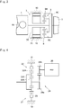
transmission device 21 is shown inFig. 4 . According to the example shown inFig. 4 , thetransmission device 21 comprises aplanetary gear unit 22, anengagement device 23, and areduction gear pair 24. Specifically, theplanetary gear unit 22 is a single-pinion planetary gear unit, and disposed coaxially with thefront propeller shaft 13 in a rear side of thefront propeller shaft 13. Theplanetary gear unit 22 comprises asun gear 22S, aring gear 22R as an internal gear arranged concentrically with thesun gear 22S, a plurality of pinion gears interposed between thesun gear 22S and thering gear 22R, and acarrier 22C supporting the pinion gears in a rotatable manner. Thecarrier 22C is connected to thefront propeller shaft 13, and theengagement device 23 is disposed between thering gear 22R and thestationary member 10. Theengagement device 23 is engaged to connect thering gear 22R o thestationary member 10 thereby stopping a rotation of thering gear 22R, and disengaged to allow thering gear 22R to rotate. For example, a dog clutch and a friction clutch may be used as theengagement device 23. - Here will be explained a structure and an advantage of the
engagement device 23. When theengagement device 23 is in engagement, thering gear 22R is halted so that theplanetary gear unit 22 serves as a speed reducing device. By contrast, when theengagement device 23 is in disengagement, the reaction force is not applied to thering gear 22R so that the planetary gear unit 22 (or the transmission device 21) is brought into the neutral state in which the torque is not transmitted through theplanetary gear unit 22. That is, when propelling the vehicle by theengine 1, thesecond motor 20 will not be rotated passively by disengaging theengagement device 23 to disconnect thesecond motor 20 from thefront propeller shaft 13. For this reason, a rotational speed of thefront propeller shaft 13 will not be restricted by a structural limitation such as a maximum speed of thesecond motor 20, even when the vehicle is propelled by theengine 1 at a high speed (e.g., higher than 130km/h). - A speed of the
second motor 20 with respect to a predetermined vehicle speed is increased with an increase in a reduction ratio achieved by thereduction gear pair 24 and theplanetary gear unit 22. However, thesecond motor 20 can be prevented from being rotated at an excessively high speed by a torque of thefront propeller shaft 13, by disengaging theengagement device 23 to disconnect thesecond motor 20 from thefront propeller shaft 13. In other words, since thesecond motor 20 can be disconnected from thefront propeller shaft 13 by disengaging theengagement device 23, the reduction ratios of thereduction gear pair 24 and theplanetary gear unit 22 can be increased. Consequently, a drive force of thefront wheels 4 can be increased to enhance acceleration when propelling the vehicle by thesecond motor 20, especially, when launching the vehicle by thesecond motor 20. - The
reduction gear pair 24 comprises a drivengear 24a connected to thesun gear 22S, and adrive gear 24b that is diametrically smaller (in other words, whose teeth number is smaller) than the drivengear 24a. Thesecond motor 20 is connected to thedrive gear 24b. Accordingly, when thesecond motor 20 is operated as a motor to generate torque, the drivengear 24a and thesun gear 22S are rotated at a lower speed than a rotational speed of thesecond motor 20. In addition, when theengagement device 23 is engaged to halt thering gear 22R, a rotational speed of thecarrier 22C as an output element is reduced lower than a rotational speed of thesun gear 22S as an input element. Consequently, a rotational speed of thefront propeller shaft 13 connected to thecarrier 22C is reduced lower than the rotational speed of thesecond motor 20. Thus, thetransmission device 21 serves as a speed reducing device. - In the example shown in
Fig. 4 , thesecond motor 20 is connected to the rear end of thefront propeller shaft 13. Specifically, thesecond motor 20 is situated in the rear side of thetransmission 5 and thetransfer 11 without interference with thetransmission 5 and thetransfer 11. In other words, thesecond motor 20 and thetransmission device 21 are arranged utilizing an existing space of the four-wheel drive vehicle underneath the floor panel. For this reason, a two-motor type hybrid vehicle may be formed without modifying the four-wheel drive hybrid vehicle significantly. In addition, since thesecond motor 20 is connected to thefront propeller shaft 13 through thetransmission device 21 serving as a speed reducing device, torque of thesecond motor 20 is delivered to thefront propeller shaft 13 while being multiplied by thetransmission device 21. For this reason, a low-torque/high speed type motor may be used as thesecond motor 20. That is, thesecond motor 20 may be downsized to be fitted easily in thevehicle body 2. - In addition, the
second motor 20 and thetransmission device 21 are arranged in a manner such that thesecond motor 20 and thetransmission device 21 do not interfere with a fuel tank Ft shown inFig. 1 . Alternatively, dimensions of the fuel tank Ft may also be altered in accordance with arrangements of thesecond motor 20 and thetransmission device 21. In this case, however, it is not necessary to modify the structure of thevehicle body 2 significantly. - According to the embodiment, the
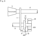
second motor 20 may also be connected always to thefront propeller shaft 13.Fig. 5 shows a modification example of the example shown inFig. 4 in which thering gear 22R is fixed to thestationary member 10 without interposing theengagement device 23, and thesecond motor 20 is connected directly to thecarrier 22C without interposing thereduction gear pair 24. - In the example shown in
Fig. 5 , thesecond motor 20 is always rotated during propulsion of the vehicle. For example, when an accelerator pedal is depressed, thesecond motor 20 may be operated as a motor by supplying electricity to thesecond motor 20 so as to assist a drive torque delivered to thefront wheels 4 by an output torque of thesecond motor 20. By contrast, when the vehicle is decelerated, thesecond motor 20 may be operated as a generator by the torque applied from thefront wheels 4 so as to regenerate energy. In the example shown inFig. 5 , since theplanetary gear unit 22 also serves as a speed reducing device, a low-torque/high speed type motor may also be used as thesecond motor 20 to downsize thesecond motor 20. In addition, in the example shown inFig. 5 , thesecond motor 20 may be disposed coaxially with thefront propeller shaft 13 while utilizing a longitudinal space in thevehicle body 2. -
Fig. 6 is shows another modification example of the example shown inFig. 4 in which theplanetary gear unit 22 is omitted and the drivengear 24a of thereduction gear pair 24 is connected directly to thefront propeller shaft 13. In the example shown inFig. 6 , thesecond motor 20 is also rotated always during propulsion of the vehicle. When an accelerator pedal is depressed, thesecond motor 20 may also be operated as a motor by supplying electricity to thesecond motor 20 so as to assist a drive torque delivered to thefront wheels 4 by an output torque of thesecond motor 20. By contrast, when the vehicle is decelerated, thesecond motor 20 may also be operated as a generator by the torque applied from thefront wheels 4 so as to regenerate energy. In the example shown inFig. 6 , thesecond motor 20 is offset from thefront propeller shaft 13. In this case, in order to avoid interference with a side member (not shown) of thevehicle body 2, it is preferable to dispose thesecond motor 20 between a center axis of therear propeller shaft 12 and a center axis of thefront propeller shaft 13. -
Fig. 7 shows an example in which thesecond motor 20 and theplanetary gear unit 22 are arranged around a rear end portion of thefront propeller shaft 13. Specifically, thesecond motor 20 and theplanetary gear unit 22 are arranged in front of thetransfer 11 in the longitudinal direction of thevehicle body 2. Thesun gear 22S of theplanetary gear unit 22 is shaped into a cylindrical gear, and fitted onto thefront propeller shaft 13. A cylindrical rotor of thesecond motor 20 is also fitted onto the front propeller shaft 13n and connected to thesun gear 22S. In the example shown inFig. 7 , in order to arrange thesecond motor 20 and theplanetary gear unit 22 without interference with thetransmission 5, thetransfer 11 may be withdrawn backwardly from thetransmission 5 to create a space for holding thesecond motor 20 and theplanetary gear unit 22. However, outer diameters of thesecond motor 20 and theplanetary gear unit 22 may be restricted to avoid interference with other members, and hence an outer diameter of thefront propeller shaft 13 may be restricted. For this reason, the example shown inFig. 7 is suitable for a vehicle in which torque applied to thefront wheels 4 or thefront propeller shaft 13 is small. -
Fig. 8 shows an example in which thesecond motor 20 and thereduction gear pair 24 are arranged concentrically with thefront propeller shaft 13, instead of thesecond motor 20 and theplanetary gear unit 22. In the example shown inFig. 8 , a space is maintained between thetransmission 5 and thetransfer 11, and thesecond motor 20 is disposed between thetransmission 5 and thetransfer 11. Thedrive gear 24b is attached to thesecond motor 20, and the drivengear 24a is fitted onto thefront propeller shaft 13 while being meshed with thedrive gear 24b. In the example shown inFig. 8 , the outer diameter of thefront propeller shaft 13 will not be especially restricted. However, since therear propeller shaft 12, thesecond motor 20, and thefront propeller shaft 13 are arranged parallel to one another in the width direction of thevehicle body 2, the example shown inFig. 8 is suitable for a vehicle having a wide width. - Thus, the four-wheel drive hybrid vehicle according to the embodiment is provided with two
motors Fig. 9 shows a control system of the four-wheel drive hybrid vehicle having thetransmission device 8 inFig. 2 and thetransmission device 21 shown inFig. 4 . An ignition timing, an opening degree of a throttle valve etc. of theengine 1, and a driving range such as a forward range and a reverse range, a gear stage etc. of thetransmission 5 may be controlled electrically. In thetransmission device 21, theengagement device 23 may be engaged and disengaged electrically. The first motor 7 (referred to as "MG1 in the drawings) and the second motor 20 (referred to as "MG2" in the drawings) are connected individually to acontroller 25 comprising abattery 25a and aninverter 25b so that each of thefirst motor 7 and thesecond motor 20 is operated selectively as a motor and a generator by thecontroller 25. - The
engine 1, thetransmission 5, thetransmission device 21, and thecontroller 25 are connected to an electronic control unit (to be abbreviated as the "ECU" hereinafter) 26. TheECU 26 is composed mainly of a microcomputer configured to execute a calculation based on an incident data and data stored in advance, and to transmit a calculation result in the form of command signal. To this end, theECU 26 receives data about a position of an accelerator pedal representing a drive demand, a vehicle speed, a pedal force applied to a brake pedal or a depression of the brake pedal representing a brake demand, a state of charge level (to be abbreviated as the "SOC" hereinafter), wheel speeds of thefront wheels 4 and therear wheels 3, a temperature of coolant for cooling theengine 1, and so on. - The operating modes of the vehicle established by the
ECU 26 are shown inFig. 10 . In the column representing "Mode" inFig. 10 , "EV" represents an Electric Vehicle mode in which the vehicle is powered without using theengine 1, "ENG Starting" represents an engine starting mode in which the stoppingengine 1 is started, and "HV" represents a Hybrid mode in which the vehicle is powered by theengine 1 and any of thefirst motor 7 and thesecond motor 20. In the hybrid mode, "Series" represents a series mode in which thesecond motor 20 is driven by the electricity generated by thefirst motor 7, and "Parallel" represents a parallel mode in which the vehicle is powered by theengine 1, thefirst motor 7, and thesecond motor 20. In the column representing "T/M", "N" represents a neutral condition in which thetransmission 5 does not transmit torque, and "D•R" represent that thetransmission 5 establishes any one of the gear stages in a forward range or a reverse range. In the column representing "Engagement Device", "ON" represents that theengagement device 23 is in engagement, "OFF" represents that theengagement device 23 is in disengagement, and "ON•OFF" represents a state that theengagement device 23 may be not only engaged but also disengaged. In the column representing "ENG", "OFF" represents that theengine 1 is stopped, "ON" represents that theengine 1 is driven to generate torque, and "Drn" represents that theengine 1 is rotated to be started (i.e., a motoring or cranking). In the columns representing "MG1" and "MG2", "OFF" represents that thefirst motor 7 or thesecond motor 20 is stopped, "M" represents that thefirst motor 7 or thesecond motor 20 is operated as a motor, "G" represents that thefirst motor 7 or thesecond motor 20 is operated as a generator, and "RG" represents that thefirst motor 7 or thesecond motor 20 regenerates electricity. - When the SOC level is sufficiently high and a depression of the accelerator pedal is small, the Electric Vehicle mode is selected. In the Electric Vehicle mode, a predetermined clutch or brake of the
transmission 5 is disengaged to bring thetransmission 5 into the neutral state, and theengine 1 is stopped by stopping a fuel supply thereto and an ignition thereof. In addition, thefirst motor 7 is also stopped. On the other hand, thesecond motor 20 is operated as a motor, and theengagement device 23 is engaged to transmit a drive torque generated by thesecond motor 20 to thefront wheels 4. In the Electric Vehicle mode, even if the low-torque/high speed type motor is used as thesecond motor 20, a drive torque can be ensured sufficiently by using thetransmission device 21 adapted to serve as a speed reducing device to multiply the output torque of thesecond motor 20. - When the accelerator pedal is returned or a brake pedal is depressed during propulsion in the Electric Vehicle mode, the
second motor 20 serves as a generator to generate electricity (i.e., regeneration). In this situation, specifically, energy of the inertially rotatingfront wheels 4 is delivered to thesecond motor 20 to be regenerated into electricity. A regeneration efficiency may be improved by increasing a vertical force at thefront wheels 4 or a slip limit of thefront wheels 4 to increase a regenerative torque or a regenerative speed. - A motoring to start the
engine 1 is carried out by thefirst motor 7. For example, a condition to start theengine 1 is satisfied when the SOC level falls below a predetermined level, when a temperature of theengine 1 falls below a predetermined level, or when the accelerator pedal is depressed to increase the drive force. When starting theengine 1, thefirst motor 7 is operated as a motor to rotate the crankshaft of theengine 1, and thetransmission 5 is brought into the neutral state to interrupt torque transmission. In this situation, thesecond motor 20 is stopped or operated as a motor depending on a running condition of the vehicle, and theengagement device 23 is engaged or disengaged depending on a running condition of the vehicle. - In the series mode, the
first motor 7 is rotated by theengine 1 to generate electricity, and thesecond motor 20 is operated as a motor by the electricity generated by thefirst motor 7 to generate a drive torque to propel the vehicle. Thus, theengine 1 is driven, and thefirst motor 7 is operated as a generator. In this situation, thetransmission 5 is brought into the neutral state so as not to deliver the drive torque of theengine 1 to therear wheels 3, and theengagement device 23 is engaged to transmit the drive torque of thesecond motor 20 to thefront wheels 4. When the vehicle is decelerated during propulsion in the series mode, thesecond motor 20 also regenerates energy as in the Electric Vehicle mode. - In the parallel mode, the vehicle is powered by the
engine 1 and both of thefirst motor 7 and thesecond motor 20. To this end, thefirst motor 7 is operated as a motor by the electricity supplied from thebattery 25a, and a predetermined gear stage (including the reverse stage) is established in thetransmission 5 to transmit the drive torque of theengine 1 to therear wheels 3. In the parallel mode, specifically, the drive torques of theengine 1 and thefirst motor 7 are delivered not only to therear wheels 3 through thetransmission 5 but also to thefront wheels 4 through thetransfer 11, and the drive torque of thesecond motor 20 is delivered to thefront wheels 4. In the parallel mode, therefore, the drive force to propel the vehicle is increased to enhance a driving performance of the vehicle especially on a rough road. When the vehicle is decelerated during propulsion in the parallel mode, both of thefirst motor 7 and thesecond motor 20 are operated as generators by delivering inertia torques of thefront wheels 4 and therear wheels 3 to thefirst motor 7 and thesecond motor 20. Since a vertical force at thefront wheels 4 or a slip limit of thefront wheels 4 is large in the parallel mode, electricity can be regenerated efficiently. - Although the above exemplary embodiments of the present disclosure have been described, it will be understood by those skilled in the art that the present application should not be limited to the described exemplary embodiments, and various changes and modifications can be made within the scope of the present disclosure. For example, the
engine 1 may also be disposed in front of therear wheels 3 in such a manner as to deliver the drive torque to thefront wheels 4 and to therear wheels 3 through thetransfer 11. In addition, in the planetary gear unit used as the transmission device, connections of the sun gear, the ring gear, and the carrier may be altered according to need.
Claims (11)
- A four-wheel drive hybrid vehicle, comprising:a first pair of drive wheels (4) disposed on a front side or rear side of a vehicle body (2); anda second pair of drive wheels (3) disposed on the other side of the vehicle body (2);characterized by:an engine (1) that is disposed on a side of the first pair of drive wheels (4);a first motor (7) that generates a torque to be added to an output torque of the engine (1);an exhaust pipe (17) for discharging exhaust gas of the engine (1) from a rear side of a vehicle body (2);a first propeller shaft (12) that delivers an output power of the engine (1) to the second pair of drive wheels (3);a transfer (11) that distributes the output power of the engine (1) to the first pair of drive wheels (4);a second propeller shaft (13) that delivers a drive force from the transfer (11) to the first pair of drive wheels (4); anda second motor (20) having a generating function, which applies torque to the first pair of drive wheels (4), and to which torque of the first pair of drive wheels (4) is applied,wherein the second propeller shaft (13) is arranged on the other side of the exhaust pipe (17) in a width direction of the vehicle body (2) across the first propeller shaft (12), andthe second motor (20) is connected to the second propeller shaft (13).
- The four-wheel drive hybrid vehicle as claimed in claim 1, further comprising:
a transmission device (21) that connects the second motor (20) to the second propeller shaft (13) in a torque transmittable manner. - The four-wheel drive hybrid vehicle as claimed in claim 2, wherein the transmission device (21) includes a speed reducing device that reduces a rotational speed of the second propeller shaft (13) lower than the rotational speed of the second motor (20).
- The four-wheel drive hybrid vehicle as claimed in claim 2 or 3, wherein the transmission device (21) comprises an engagement device (23) that selectively interrupts torque transmission between the second motor (20) and the second propeller shaft (13).
- The four-wheel drive hybrid vehicle as claimed in any of claims 1 to 4,
wherein the second propeller shaft (13) extends in a longitudinal direction of the vehicle body (2),
the second propeller shaft (13) comprises a first end situated on a side of the first pair of drive wheels (4), and a second end situated on the other side of the first end in the longitudinal direction of the vehicle body (2), and
the second motor (20) is disposed on the second end side. - The four-wheel drive hybrid vehicle as claimed in any of claim 2 to 4,
wherein the second propeller shaft (13) extends in a longitudinal direction of the vehicle body (2),
the second propeller shaft (13) comprises a first end situated on a side of the first pairs of drive wheels (4), and a second end situated on the other side of the first end in the longitudinal direction of the vehicle body (2), and
the second motor (20) and the transmission device (21) are disposed on the second end side. - The four-wheel drive hybrid vehicle as claimed in any of claims 1 to 6, wherein the first pair of drive wheels (4) is a pair of front wheels, and the second pair of wheels (3) is a pair of rear wheels.
- The four-wheel drive hybrid vehicle as claimed in any of claims 1 to 7, further comprising:a transmission (5) that is connected to an output side of the engine (1),wherein the transmission (5) comprises a clutch (6) that is engaged to transmit torque, and that is disengaged to interrupt torque transmission.
- The four-wheel drive hybrid vehicle as claimed in claim 8,
wherein the first motor (7) is disposed on an input side of the transmission (5) coaxially with the engine (1), and
the transfer (11) is connected to an output side of the transmission (5). - The four-wheel drive hybrid vehicle as claimed in claim 9, wherein the second motor (20) is situated closer to the second pair of wheels (3) than the transfer (11).
- The four-wheel drive hybrid vehicle as claimed in any of claims 1 to 10, wherein the first motor (7) has a generating function.
Applications Claiming Priority (1)
| Application Number | Priority Date | Filing Date | Title |
|---|---|---|---|
| JP2017084849A JP6624151B2 (en) | 2017-04-21 | 2017-04-21 | Hybrid four-wheel drive vehicle |
Publications (2)
| Publication Number | Publication Date |
|---|---|
| EP3392071A1 true EP3392071A1 (en) | 2018-10-24 |
| EP3392071B1 EP3392071B1 (en) | 2022-08-24 |
Family
ID=62044612
Family Applications (1)
| Application Number | Title | Priority Date | Filing Date |
|---|---|---|---|
| EP18168593.4A Active EP3392071B1 (en) | 2017-04-21 | 2018-04-20 | Four-wheel drive hybrid vehicle |
Country Status (13)
| Country | Link |
|---|---|
| US (1) | US11046169B2 (en) |
| EP (1) | EP3392071B1 (en) |
| JP (1) | JP6624151B2 (en) |
| KR (1) | KR102031724B1 (en) |
| CN (1) | CN108725180B (en) |
| AU (1) | AU2018202614B2 (en) |
| BR (1) | BR102018008066A2 (en) |
| CA (1) | CA3002306C (en) |
| MX (1) | MX2018004990A (en) |
| MY (1) | MY190575A (en) |
| PH (1) | PH12018000110A1 (en) |
| RU (1) | RU2693778C1 (en) |
| TW (1) | TWI668137B (en) |
Cited By (2)
| Publication number | Priority date | Publication date | Assignee | Title |
|---|---|---|---|---|
| CN112297838A (en) * | 2019-07-31 | 2021-02-02 | 株式会社斯巴鲁 | Driving device of electric motor type four-wheel drive vehicle |
| EP4219979A4 (en) * | 2020-09-25 | 2024-04-10 | Kubota Corporation | Rotary electrical machine |
Families Citing this family (9)
| Publication number | Priority date | Publication date | Assignee | Title |
|---|---|---|---|---|
| JP7052262B2 (en) | 2017-09-08 | 2022-04-12 | トヨタ自動車株式会社 | Drive device for four-wheel drive vehicles |
| JP7070240B2 (en) | 2018-08-23 | 2022-05-18 | トヨタ自動車株式会社 | Hybrid vehicle |
| JP6724091B2 (en) * | 2018-09-06 | 2020-07-15 | 本田技研工業株式会社 | Hybrid vehicle |
| CN112639169B (en) | 2018-09-21 | 2023-12-01 | 旭化成株式会社 | Laminated body, method of preserving the laminated body, method of transporting the laminated body, protection of the laminated body and its winding body |
| JP7352425B2 (en) * | 2019-09-25 | 2023-09-28 | 株式会社Subaru | Electric motor type four-wheel drive vehicle drive system |
| JP7414510B2 (en) * | 2019-12-19 | 2024-01-16 | 株式会社Subaru | Vehicle drive system |
| JP2021138309A (en) * | 2020-03-06 | 2021-09-16 | 本田技研工業株式会社 | vehicle |
| US11408340B2 (en) * | 2020-05-15 | 2022-08-09 | Pratt & Whitney Canada Corp. | Twin-engine system with electric drive |
| JP7552300B2 (en) * | 2020-11-27 | 2024-09-18 | マツダ株式会社 | Vehicle undercarriage |
Citations (3)
| Publication number | Priority date | Publication date | Assignee | Title |
|---|---|---|---|---|
| US20070267233A1 (en) * | 2001-04-24 | 2007-11-22 | Magna Powertrain Usa, Inc. | Electrically-Driven Transfer Case With Power Take-off |
| US20090186734A1 (en) * | 2008-01-21 | 2009-07-23 | Ford Global Technologies, Llc | Vehicle hybrid powertrain system and method of operating same |
| US20150360572A1 (en) * | 2014-06-13 | 2015-12-17 | Mitsubishi Jidosha Engineering Kabushiki Kaisha | Electric vehicle |
Family Cites Families (21)
| Publication number | Priority date | Publication date | Assignee | Title |
|---|---|---|---|---|
| JPH04116622U (en) * | 1991-03-27 | 1992-10-19 | マツダ株式会社 | Automobile lower body structure |
| JP3376948B2 (en) | 1999-03-19 | 2003-02-17 | トヨタ自動車株式会社 | Exhaust gas purification control device for hybrid vehicles |
| JP3593983B2 (en) | 2001-01-16 | 2004-11-24 | 日産自動車株式会社 | Vehicle driving force control device |
| US6464608B2 (en) * | 2001-02-08 | 2002-10-15 | New Venture Gear Inc. | Transfer case for hybrid vehicle |
| US6648785B2 (en) * | 2001-12-05 | 2003-11-18 | New Venture Gear, Inc. | Transfer case for hybrid vehicle |
| JP3646705B2 (en) * | 2002-02-15 | 2005-05-11 | 日産自動車株式会社 | Electric motor mounting structure for hybrid four-wheel drive vehicles |
| US7520354B2 (en) * | 2002-05-02 | 2009-04-21 | Oshkosh Truck Corporation | Hybrid vehicle with combustion engine/electric motor drive |
| JP2005001567A (en) * | 2003-06-12 | 2005-01-06 | Fuji Heavy Ind Ltd | Vehicle traveling device |
| JP2005082048A (en) * | 2003-09-09 | 2005-03-31 | Toyota Motor Corp | Drive switching control device for multi-wheel drive vehicle |
| AT8336U1 (en) * | 2004-09-27 | 2006-06-15 | Magna Steyr Fahrzeugtechnik Ag | DRIVE UNIT FOR MOTOR VEHICLE WITH HYBRID DRIVE IN LENGTH ORDER |
| US7455135B2 (en) * | 2005-08-15 | 2008-11-25 | Ford Global Technologies, Llc | Torque transfer case for a hybrid electric vehicle |
| US8011461B2 (en) * | 2008-02-14 | 2011-09-06 | Illinois Institute Of Technology | Hybrid electric conversion kit for rear-wheel drive, all wheel drive, and four wheel drive vehicles |
| GB2488969A (en) * | 2011-02-01 | 2012-09-19 | Land Rover Uk Ltd | Hybrid electric vehicle control using virtual speed of an actuator |
| JP5701116B2 (en) * | 2011-03-17 | 2015-04-15 | 富士重工業株式会社 | Power transmission device for hybrid vehicle |
| DE102012100865B4 (en) * | 2012-02-02 | 2016-10-27 | Gkn Driveline International Gmbh | Drive arrangement with electric machine and motor vehicle with such a drive arrangement |
| ES2660552T3 (en) * | 2012-09-06 | 2018-03-22 | Iveco S.P.A. | Vehicle comprising a torque distributor for two axes, method to control the same, computer program and media that can be read by a computer |
| JP5660104B2 (en) * | 2012-10-22 | 2015-01-28 | トヨタ自動車株式会社 | vehicle |
| JP2015196413A (en) | 2014-03-31 | 2015-11-09 | スズキ株式会社 | hybrid four-wheel-drive vehicle |
| US10569638B2 (en) * | 2014-06-25 | 2020-02-25 | Heinz Welschoff | All electric vehicle without plug-in requirement |
| KR101534750B1 (en) * | 2014-08-13 | 2015-07-07 | 현대자동차 주식회사 | Power transmission system of hybrid electric vehicle |
| US9937919B2 (en) * | 2016-03-10 | 2018-04-10 | Ford Global Technologies, Llc | System and method for coupled and decoupled engine starting in a hybrid vehicle |
-
2017
- 2017-04-21 JP JP2017084849A patent/JP6624151B2/en active Active
-
2018
- 2018-04-16 AU AU2018202614A patent/AU2018202614B2/en not_active Ceased
- 2018-04-17 PH PH12018000110A patent/PH12018000110A1/en unknown
- 2018-04-18 MY MYPI2018701517A patent/MY190575A/en unknown
- 2018-04-18 KR KR1020180044914A patent/KR102031724B1/en not_active Expired - Fee Related
- 2018-04-19 TW TW107113290A patent/TWI668137B/en not_active IP Right Cessation
- 2018-04-19 US US15/957,300 patent/US11046169B2/en not_active Expired - Fee Related
- 2018-04-20 EP EP18168593.4A patent/EP3392071B1/en active Active
- 2018-04-20 MX MX2018004990A patent/MX2018004990A/en unknown
- 2018-04-20 RU RU2018114696A patent/RU2693778C1/en active
- 2018-04-20 CN CN201810359033.3A patent/CN108725180B/en not_active Expired - Fee Related
- 2018-04-20 BR BR102018008066-0A patent/BR102018008066A2/en not_active Application Discontinuation
- 2018-04-20 CA CA3002306A patent/CA3002306C/en active Active
Patent Citations (4)
| Publication number | Priority date | Publication date | Assignee | Title |
|---|---|---|---|---|
| US20070267233A1 (en) * | 2001-04-24 | 2007-11-22 | Magna Powertrain Usa, Inc. | Electrically-Driven Transfer Case With Power Take-off |
| US20090186734A1 (en) * | 2008-01-21 | 2009-07-23 | Ford Global Technologies, Llc | Vehicle hybrid powertrain system and method of operating same |
| US20150360572A1 (en) * | 2014-06-13 | 2015-12-17 | Mitsubishi Jidosha Engineering Kabushiki Kaisha | Electric vehicle |
| JP2016002772A (en) | 2014-06-13 | 2016-01-12 | 三菱自動車工業株式会社 | Electric vehicle |
Cited By (3)
| Publication number | Priority date | Publication date | Assignee | Title |
|---|---|---|---|---|
| CN112297838A (en) * | 2019-07-31 | 2021-02-02 | 株式会社斯巴鲁 | Driving device of electric motor type four-wheel drive vehicle |
| EP4219979A4 (en) * | 2020-09-25 | 2024-04-10 | Kubota Corporation | Rotary electrical machine |
| US12323037B2 (en) | 2020-09-25 | 2025-06-03 | Kubota Corporation | Rotating electrical machine |
Also Published As
| Publication number | Publication date |
|---|---|
| CA3002306C (en) | 2019-12-10 |
| AU2018202614A1 (en) | 2018-11-08 |
| TWI668137B (en) | 2019-08-11 |
| US11046169B2 (en) | 2021-06-29 |
| CA3002306A1 (en) | 2018-10-21 |
| JP2018177171A (en) | 2018-11-15 |
| CN108725180B (en) | 2021-12-24 |
| KR20180118536A (en) | 2018-10-31 |
| MX2018004990A (en) | 2018-11-09 |
| PH12018000110A1 (en) | 2018-11-12 |
| KR102031724B1 (en) | 2019-10-14 |
| JP6624151B2 (en) | 2019-12-25 |
| RU2693778C1 (en) | 2019-07-04 |
| EP3392071B1 (en) | 2022-08-24 |
| MY190575A (en) | 2022-04-27 |
| BR102018008066A2 (en) | 2018-11-06 |
| CN108725180A (en) | 2018-11-02 |
| AU2018202614B2 (en) | 2019-08-22 |
| TW201841784A (en) | 2018-12-01 |
| US20180304738A1 (en) | 2018-10-25 |
Similar Documents
| Publication | Publication Date | Title |
|---|---|---|
| EP3392071B1 (en) | Four-wheel drive hybrid vehicle | |
| US10017040B2 (en) | Drive unit for a hybrid vehicle | |
| US7972235B2 (en) | Hybrid powertrain system having selectively connectable engine, motor/generator, and transmission | |
| JP4229173B2 (en) | Power output device, automobile equipped with the same, and method for controlling power output device | |
| JP4229175B2 (en) | Power output device, automobile equipped with the same, and method for controlling power output device | |
| JP4229174B2 (en) | Power output device, automobile equipped with the same, and method for controlling power output device | |
| JP4063310B1 (en) | POWER OUTPUT DEVICE, HYBRID VEHICLE HAVING THE SAME, AND METHOD FOR CONTROLLING POWER OUTPUT DEVICE | |
| KR102243093B1 (en) | Hybrid vehicle | |
| US10759413B2 (en) | Control system for hybrid vehicle | |
| US10202113B2 (en) | Engine starting control system for hybrid vehicle | |
| US10144411B2 (en) | Vehicle system | |
| JP2001260684A (en) | Front and rear wheel drive vehicles | |
| JP2012254739A (en) | Control device of hybrid vehicle | |
| JP2019151232A (en) | Control device for vehicle | |
| JP2019069646A (en) | Four-wheel-drive vehicle | |
| US20220063586A1 (en) | Vehicle control system | |
| JP2022037659A (en) | Vehicular control apparatus | |
| JP2023081112A (en) | Driving force control device for hybrid vehicle | |
| JP2004242464A (en) | Hybrid vehicle drive system |
Legal Events
| Date | Code | Title | Description |
|---|---|---|---|
| PUAI | Public reference made under article 153(3) epc to a published international application that has entered the european phase |
Free format text: ORIGINAL CODE: 0009012 |
|
| STAA | Information on the status of an ep patent application or granted ep patent |
Free format text: STATUS: REQUEST FOR EXAMINATION WAS MADE |
|
| 17P | Request for examination filed |
Effective date: 20180521 |
|
| AK | Designated contracting states |
Kind code of ref document: A1 Designated state(s): AL AT BE BG CH CY CZ DE DK EE ES FI FR GB GR HR HU IE IS IT LI LT LU LV MC MK MT NL NO PL PT RO RS SE SI SK SM TR |
|
| AX | Request for extension of the european patent |
Extension state: BA ME |
|
| RIC1 | Information provided on ipc code assigned before grant |
Ipc: B60K 6/40 20071001ALI20180905BHEP Ipc: B60K 6/442 20071001ALI20180905BHEP Ipc: B60K 6/52 20071001AFI20180905BHEP Ipc: B60K 17/344 20060101ALI20180905BHEP |
|
| STAA | Information on the status of an ep patent application or granted ep patent |
Free format text: STATUS: EXAMINATION IS IN PROGRESS |
|
| 17Q | First examination report despatched |
Effective date: 20210604 |
|
| GRAP | Despatch of communication of intention to grant a patent |
Free format text: ORIGINAL CODE: EPIDOSNIGR1 |
|
| STAA | Information on the status of an ep patent application or granted ep patent |
Free format text: STATUS: GRANT OF PATENT IS INTENDED |
|
| INTG | Intention to grant announced |
Effective date: 20220318 |
|
| RIN1 | Information on inventor provided before grant (corrected) |
Inventor name: KUWAHARA, SEIJI |
|
| GRAS | Grant fee paid |
Free format text: ORIGINAL CODE: EPIDOSNIGR3 |
|
| GRAA | (expected) grant |
Free format text: ORIGINAL CODE: 0009210 |
|
| STAA | Information on the status of an ep patent application or granted ep patent |
Free format text: STATUS: THE PATENT HAS BEEN GRANTED |
|
| AK | Designated contracting states |
Kind code of ref document: B1 Designated state(s): AL AT BE BG CH CY CZ DE DK EE ES FI FR GB GR HR HU IE IS IT LI LT LU LV MC MK MT NL NO PL PT RO RS SE SI SK SM TR |
|
| REG | Reference to a national code |
Ref country code: CH Ref legal event code: EP |
|
| REG | Reference to a national code |
Ref country code: DE Ref legal event code: R096 Ref document number: 602018039596 Country of ref document: DE |
|
| REG | Reference to a national code |
Ref country code: IE Ref legal event code: FG4D |
|
| REG | Reference to a national code |
Ref country code: AT Ref legal event code: REF Ref document number: 1513415 Country of ref document: AT Kind code of ref document: T Effective date: 20220915 |
|
| REG | Reference to a national code |
Ref country code: LT Ref legal event code: MG9D |
|
| REG | Reference to a national code |
Ref country code: NL Ref legal event code: MP Effective date: 20220824 |
|
| PG25 | Lapsed in a contracting state [announced via postgrant information from national office to epo] |
Ref country code: SE Free format text: LAPSE BECAUSE OF FAILURE TO SUBMIT A TRANSLATION OF THE DESCRIPTION OR TO PAY THE FEE WITHIN THE PRESCRIBED TIME-LIMIT Effective date: 20220824 Ref country code: RS Free format text: LAPSE BECAUSE OF FAILURE TO SUBMIT A TRANSLATION OF THE DESCRIPTION OR TO PAY THE FEE WITHIN THE PRESCRIBED TIME-LIMIT Effective date: 20220824 Ref country code: PT Free format text: LAPSE BECAUSE OF FAILURE TO SUBMIT A TRANSLATION OF THE DESCRIPTION OR TO PAY THE FEE WITHIN THE PRESCRIBED TIME-LIMIT Effective date: 20221226 Ref country code: NO Free format text: LAPSE BECAUSE OF FAILURE TO SUBMIT A TRANSLATION OF THE DESCRIPTION OR TO PAY THE FEE WITHIN THE PRESCRIBED TIME-LIMIT Effective date: 20221124 Ref country code: NL Free format text: LAPSE BECAUSE OF FAILURE TO SUBMIT A TRANSLATION OF THE DESCRIPTION OR TO PAY THE FEE WITHIN THE PRESCRIBED TIME-LIMIT Effective date: 20220824 Ref country code: LV Free format text: LAPSE BECAUSE OF FAILURE TO SUBMIT A TRANSLATION OF THE DESCRIPTION OR TO PAY THE FEE WITHIN THE PRESCRIBED TIME-LIMIT Effective date: 20220824 Ref country code: LT Free format text: LAPSE BECAUSE OF FAILURE TO SUBMIT A TRANSLATION OF THE DESCRIPTION OR TO PAY THE FEE WITHIN THE PRESCRIBED TIME-LIMIT Effective date: 20220824 Ref country code: FI Free format text: LAPSE BECAUSE OF FAILURE TO SUBMIT A TRANSLATION OF THE DESCRIPTION OR TO PAY THE FEE WITHIN THE PRESCRIBED TIME-LIMIT Effective date: 20220824 |
|
| REG | Reference to a national code |
Ref country code: AT Ref legal event code: MK05 Ref document number: 1513415 Country of ref document: AT Kind code of ref document: T Effective date: 20220824 |
|
| PG25 | Lapsed in a contracting state [announced via postgrant information from national office to epo] |
Ref country code: PL Free format text: LAPSE BECAUSE OF FAILURE TO SUBMIT A TRANSLATION OF THE DESCRIPTION OR TO PAY THE FEE WITHIN THE PRESCRIBED TIME-LIMIT Effective date: 20220824 Ref country code: IS Free format text: LAPSE BECAUSE OF FAILURE TO SUBMIT A TRANSLATION OF THE DESCRIPTION OR TO PAY THE FEE WITHIN THE PRESCRIBED TIME-LIMIT Effective date: 20221224 Ref country code: HR Free format text: LAPSE BECAUSE OF FAILURE TO SUBMIT A TRANSLATION OF THE DESCRIPTION OR TO PAY THE FEE WITHIN THE PRESCRIBED TIME-LIMIT Effective date: 20220824 Ref country code: GR Free format text: LAPSE BECAUSE OF FAILURE TO SUBMIT A TRANSLATION OF THE DESCRIPTION OR TO PAY THE FEE WITHIN THE PRESCRIBED TIME-LIMIT Effective date: 20221125 |
|
| PG25 | Lapsed in a contracting state [announced via postgrant information from national office to epo] |
Ref country code: SM Free format text: LAPSE BECAUSE OF FAILURE TO SUBMIT A TRANSLATION OF THE DESCRIPTION OR TO PAY THE FEE WITHIN THE PRESCRIBED TIME-LIMIT Effective date: 20220824 Ref country code: RO Free format text: LAPSE BECAUSE OF FAILURE TO SUBMIT A TRANSLATION OF THE DESCRIPTION OR TO PAY THE FEE WITHIN THE PRESCRIBED TIME-LIMIT Effective date: 20220824 Ref country code: ES Free format text: LAPSE BECAUSE OF FAILURE TO SUBMIT A TRANSLATION OF THE DESCRIPTION OR TO PAY THE FEE WITHIN THE PRESCRIBED TIME-LIMIT Effective date: 20220824 Ref country code: DK Free format text: LAPSE BECAUSE OF FAILURE TO SUBMIT A TRANSLATION OF THE DESCRIPTION OR TO PAY THE FEE WITHIN THE PRESCRIBED TIME-LIMIT Effective date: 20220824 Ref country code: CZ Free format text: LAPSE BECAUSE OF FAILURE TO SUBMIT A TRANSLATION OF THE DESCRIPTION OR TO PAY THE FEE WITHIN THE PRESCRIBED TIME-LIMIT Effective date: 20220824 Ref country code: AT Free format text: LAPSE BECAUSE OF FAILURE TO SUBMIT A TRANSLATION OF THE DESCRIPTION OR TO PAY THE FEE WITHIN THE PRESCRIBED TIME-LIMIT Effective date: 20220824 |
|
| REG | Reference to a national code |
Ref country code: DE Ref legal event code: R097 Ref document number: 602018039596 Country of ref document: DE |
|
| PG25 | Lapsed in a contracting state [announced via postgrant information from national office to epo] |
Ref country code: SK Free format text: LAPSE BECAUSE OF FAILURE TO SUBMIT A TRANSLATION OF THE DESCRIPTION OR TO PAY THE FEE WITHIN THE PRESCRIBED TIME-LIMIT Effective date: 20220824 Ref country code: EE Free format text: LAPSE BECAUSE OF FAILURE TO SUBMIT A TRANSLATION OF THE DESCRIPTION OR TO PAY THE FEE WITHIN THE PRESCRIBED TIME-LIMIT Effective date: 20220824 |
|
| P01 | Opt-out of the competence of the unified patent court (upc) registered |
Effective date: 20230427 |
|
| REG | Reference to a national code |
Ref country code: DE Ref legal event code: R084 Ref document number: 602018039596 Country of ref document: DE |
|
| PG25 | Lapsed in a contracting state [announced via postgrant information from national office to epo] |
Ref country code: AL Free format text: LAPSE BECAUSE OF FAILURE TO SUBMIT A TRANSLATION OF THE DESCRIPTION OR TO PAY THE FEE WITHIN THE PRESCRIBED TIME-LIMIT Effective date: 20220824 |
|
| PLBE | No opposition filed within time limit |
Free format text: ORIGINAL CODE: 0009261 |
|
| STAA | Information on the status of an ep patent application or granted ep patent |
Free format text: STATUS: NO OPPOSITION FILED WITHIN TIME LIMIT |
|
| 26N | No opposition filed |
Effective date: 20230525 |
|
| REG | Reference to a national code |
Ref country code: GB Ref legal event code: 746 Effective date: 20230801 |
|
| PG25 | Lapsed in a contracting state [announced via postgrant information from national office to epo] |
Ref country code: SI Free format text: LAPSE BECAUSE OF FAILURE TO SUBMIT A TRANSLATION OF THE DESCRIPTION OR TO PAY THE FEE WITHIN THE PRESCRIBED TIME-LIMIT Effective date: 20220824 |
|
| REG | Reference to a national code |
Ref country code: CH Ref legal event code: PL |
|
| PG25 | Lapsed in a contracting state [announced via postgrant information from national office to epo] |
Ref country code: LU Free format text: LAPSE BECAUSE OF NON-PAYMENT OF DUE FEES Effective date: 20230420 |
|
| REG | Reference to a national code |
Ref country code: BE Ref legal event code: MM Effective date: 20230430 |
|
| PG25 | Lapsed in a contracting state [announced via postgrant information from national office to epo] |
Ref country code: MC Free format text: LAPSE BECAUSE OF FAILURE TO SUBMIT A TRANSLATION OF THE DESCRIPTION OR TO PAY THE FEE WITHIN THE PRESCRIBED TIME-LIMIT Effective date: 20220824 |
|
| PG25 | Lapsed in a contracting state [announced via postgrant information from national office to epo] |
Ref country code: MC Free format text: LAPSE BECAUSE OF FAILURE TO SUBMIT A TRANSLATION OF THE DESCRIPTION OR TO PAY THE FEE WITHIN THE PRESCRIBED TIME-LIMIT Effective date: 20220824 Ref country code: LI Free format text: LAPSE BECAUSE OF NON-PAYMENT OF DUE FEES Effective date: 20230430 Ref country code: CH Free format text: LAPSE BECAUSE OF NON-PAYMENT OF DUE FEES Effective date: 20230430 |
|
| REG | Reference to a national code |
Ref country code: IE Ref legal event code: MM4A |
|
| PG25 | Lapsed in a contracting state [announced via postgrant information from national office to epo] |
Ref country code: BE Free format text: LAPSE BECAUSE OF NON-PAYMENT OF DUE FEES Effective date: 20230430 |
|
| PG25 | Lapsed in a contracting state [announced via postgrant information from national office to epo] |
Ref country code: IE Free format text: LAPSE BECAUSE OF NON-PAYMENT OF DUE FEES Effective date: 20230420 |
|
| PG25 | Lapsed in a contracting state [announced via postgrant information from national office to epo] |
Ref country code: IE Free format text: LAPSE BECAUSE OF NON-PAYMENT OF DUE FEES Effective date: 20230420 |
|
| PG25 | Lapsed in a contracting state [announced via postgrant information from national office to epo] |
Ref country code: IT Free format text: LAPSE BECAUSE OF FAILURE TO SUBMIT A TRANSLATION OF THE DESCRIPTION OR TO PAY THE FEE WITHIN THE PRESCRIBED TIME-LIMIT Effective date: 20220824 |
|
| PG25 | Lapsed in a contracting state [announced via postgrant information from national office to epo] |
Ref country code: BG Free format text: LAPSE BECAUSE OF FAILURE TO SUBMIT A TRANSLATION OF THE DESCRIPTION OR TO PAY THE FEE WITHIN THE PRESCRIBED TIME-LIMIT Effective date: 20220824 |
|
| PG25 | Lapsed in a contracting state [announced via postgrant information from national office to epo] |
Ref country code: BG Free format text: LAPSE BECAUSE OF FAILURE TO SUBMIT A TRANSLATION OF THE DESCRIPTION OR TO PAY THE FEE WITHIN THE PRESCRIBED TIME-LIMIT Effective date: 20220824 |
|
| PGFP | Annual fee paid to national office [announced via postgrant information from national office to epo] |
Ref country code: DE Payment date: 20250305 Year of fee payment: 8 |
|
| PG25 | Lapsed in a contracting state [announced via postgrant information from national office to epo] |
Ref country code: CY Free format text: LAPSE BECAUSE OF FAILURE TO SUBMIT A TRANSLATION OF THE DESCRIPTION OR TO PAY THE FEE WITHIN THE PRESCRIBED TIME-LIMIT; INVALID AB INITIO Effective date: 20180420 |
|
| PG25 | Lapsed in a contracting state [announced via postgrant information from national office to epo] |
Ref country code: HU Free format text: LAPSE BECAUSE OF FAILURE TO SUBMIT A TRANSLATION OF THE DESCRIPTION OR TO PAY THE FEE WITHIN THE PRESCRIBED TIME-LIMIT; INVALID AB INITIO Effective date: 20180420 |
|
| PG25 | Lapsed in a contracting state [announced via postgrant information from national office to epo] |
Ref country code: TR Free format text: LAPSE BECAUSE OF FAILURE TO SUBMIT A TRANSLATION OF THE DESCRIPTION OR TO PAY THE FEE WITHIN THE PRESCRIBED TIME-LIMIT Effective date: 20220824 |
|
| PGFP | Annual fee paid to national office [announced via postgrant information from national office to epo] |
Ref country code: GB Payment date: 20260313 Year of fee payment: 9 |
|
| PGFP | Annual fee paid to national office [announced via postgrant information from national office to epo] |
Ref country code: FR Payment date: 20260309 Year of fee payment: 9 |