EP3391858A2 - Constrained shell for modular dual mobility system - Google Patents
Constrained shell for modular dual mobility system Download PDFInfo
- Publication number
- EP3391858A2 EP3391858A2 EP18154625.0A EP18154625A EP3391858A2 EP 3391858 A2 EP3391858 A2 EP 3391858A2 EP 18154625 A EP18154625 A EP 18154625A EP 3391858 A2 EP3391858 A2 EP 3391858A2
- Authority
- EP
- European Patent Office
- Prior art keywords
- interior
- insert
- prosthetic device
- end surface
- shell
- Prior art date
- Legal status (The legal status is an assumption and is not a legal conclusion. Google has not performed a legal analysis and makes no representation as to the accuracy of the status listed.)
- Granted
Links
Images




Classifications
-
- A—HUMAN NECESSITIES
- A61—MEDICAL OR VETERINARY SCIENCE; HYGIENE
- A61F—FILTERS IMPLANTABLE INTO BLOOD VESSELS; PROSTHESES; DEVICES PROVIDING PATENCY TO, OR PREVENTING COLLAPSING OF, TUBULAR STRUCTURES OF THE BODY, e.g. STENTS; ORTHOPAEDIC, NURSING OR CONTRACEPTIVE DEVICES; FOMENTATION; TREATMENT OR PROTECTION OF EYES OR EARS; BANDAGES, DRESSINGS OR ABSORBENT PADS; FIRST-AID KITS
- A61F2/00—Filters implantable into blood vessels; Prostheses, i.e. artificial substitutes or replacements for parts of the body; Appliances for connecting them with the body; Devices providing patency to, or preventing collapsing of, tubular structures of the body, e.g. stents
- A61F2/02—Prostheses implantable into the body
- A61F2/30—Joints
- A61F2/32—Joints for the hip
- A61F2/34—Acetabular cups
-
- A—HUMAN NECESSITIES
- A61—MEDICAL OR VETERINARY SCIENCE; HYGIENE
- A61F—FILTERS IMPLANTABLE INTO BLOOD VESSELS; PROSTHESES; DEVICES PROVIDING PATENCY TO, OR PREVENTING COLLAPSING OF, TUBULAR STRUCTURES OF THE BODY, e.g. STENTS; ORTHOPAEDIC, NURSING OR CONTRACEPTIVE DEVICES; FOMENTATION; TREATMENT OR PROTECTION OF EYES OR EARS; BANDAGES, DRESSINGS OR ABSORBENT PADS; FIRST-AID KITS
- A61F2/00—Filters implantable into blood vessels; Prostheses, i.e. artificial substitutes or replacements for parts of the body; Appliances for connecting them with the body; Devices providing patency to, or preventing collapsing of, tubular structures of the body, e.g. stents
- A61F2/02—Prostheses implantable into the body
- A61F2/30—Joints
- A61F2/30721—Accessories
- A61F2/30724—Spacers for centering an implant in a bone cavity, e.g. in a cement-receiving cavity
-
- A—HUMAN NECESSITIES
- A61—MEDICAL OR VETERINARY SCIENCE; HYGIENE
- A61F—FILTERS IMPLANTABLE INTO BLOOD VESSELS; PROSTHESES; DEVICES PROVIDING PATENCY TO, OR PREVENTING COLLAPSING OF, TUBULAR STRUCTURES OF THE BODY, e.g. STENTS; ORTHOPAEDIC, NURSING OR CONTRACEPTIVE DEVICES; FOMENTATION; TREATMENT OR PROTECTION OF EYES OR EARS; BANDAGES, DRESSINGS OR ABSORBENT PADS; FIRST-AID KITS
- A61F2/00—Filters implantable into blood vessels; Prostheses, i.e. artificial substitutes or replacements for parts of the body; Appliances for connecting them with the body; Devices providing patency to, or preventing collapsing of, tubular structures of the body, e.g. stents
- A61F2/02—Prostheses implantable into the body
- A61F2/30—Joints
- A61F2/32—Joints for the hip
-
- A—HUMAN NECESSITIES
- A61—MEDICAL OR VETERINARY SCIENCE; HYGIENE
- A61F—FILTERS IMPLANTABLE INTO BLOOD VESSELS; PROSTHESES; DEVICES PROVIDING PATENCY TO, OR PREVENTING COLLAPSING OF, TUBULAR STRUCTURES OF THE BODY, e.g. STENTS; ORTHOPAEDIC, NURSING OR CONTRACEPTIVE DEVICES; FOMENTATION; TREATMENT OR PROTECTION OF EYES OR EARS; BANDAGES, DRESSINGS OR ABSORBENT PADS; FIRST-AID KITS
- A61F2/00—Filters implantable into blood vessels; Prostheses, i.e. artificial substitutes or replacements for parts of the body; Appliances for connecting them with the body; Devices providing patency to, or preventing collapsing of, tubular structures of the body, e.g. stents
- A61F2/02—Prostheses implantable into the body
- A61F2/30—Joints
- A61F2/32—Joints for the hip
- A61F2002/3208—Bipolar or multipolar joints, e.g. having a femoral head articulating within an intermediate acetabular shell whilst said shell articulates within the natural acetabular socket or within an artificial outer shell
-
- A—HUMAN NECESSITIES
- A61—MEDICAL OR VETERINARY SCIENCE; HYGIENE
- A61F—FILTERS IMPLANTABLE INTO BLOOD VESSELS; PROSTHESES; DEVICES PROVIDING PATENCY TO, OR PREVENTING COLLAPSING OF, TUBULAR STRUCTURES OF THE BODY, e.g. STENTS; ORTHOPAEDIC, NURSING OR CONTRACEPTIVE DEVICES; FOMENTATION; TREATMENT OR PROTECTION OF EYES OR EARS; BANDAGES, DRESSINGS OR ABSORBENT PADS; FIRST-AID KITS
- A61F2/00—Filters implantable into blood vessels; Prostheses, i.e. artificial substitutes or replacements for parts of the body; Appliances for connecting them with the body; Devices providing patency to, or preventing collapsing of, tubular structures of the body, e.g. stents
- A61F2/02—Prostheses implantable into the body
- A61F2/30—Joints
- A61F2/32—Joints for the hip
- A61F2002/3233—Joints for the hip having anti-luxation means for preventing complete dislocation of the femoral head from the acetabular cup
-
- A—HUMAN NECESSITIES
- A61—MEDICAL OR VETERINARY SCIENCE; HYGIENE
- A61F—FILTERS IMPLANTABLE INTO BLOOD VESSELS; PROSTHESES; DEVICES PROVIDING PATENCY TO, OR PREVENTING COLLAPSING OF, TUBULAR STRUCTURES OF THE BODY, e.g. STENTS; ORTHOPAEDIC, NURSING OR CONTRACEPTIVE DEVICES; FOMENTATION; TREATMENT OR PROTECTION OF EYES OR EARS; BANDAGES, DRESSINGS OR ABSORBENT PADS; FIRST-AID KITS
- A61F2/00—Filters implantable into blood vessels; Prostheses, i.e. artificial substitutes or replacements for parts of the body; Appliances for connecting them with the body; Devices providing patency to, or preventing collapsing of, tubular structures of the body, e.g. stents
- A61F2/02—Prostheses implantable into the body
- A61F2/30—Joints
- A61F2/32—Joints for the hip
- A61F2/34—Acetabular cups
- A61F2002/3443—Acetabular cups with an anti-luxation elevated rim portion, e.g. on the inner shell
Definitions
- Prosthetic devices have been used to supplement or replace components of ball-and-socket joints of the body. Such devices have included liners dimensioned to accommodate placement and securement of an insert into the liner. One example of such securement involves a "snap fit" where the insert snaps into place within the liner. Such devices are often limited in the mobility offered. Other examples include liners with irregularly shaped interior surfaces within a cavity of the liner to aid in constraint of inserts when disposed therein. For these devices, an ability to constrain an insert may be limited. Other devices require an insert to be translated after advancement but prior to rotating the insert into a constrained position. Without translation in such devices, interior walls of a corresponding liner prevent rotation. This translation requirement increases cycle time during fabrication. Still further devices incorporate locking mechanisms or other elements to aid in constraint of an insert into a liner. Such devices are thus more prone to failure due to the additional components necessary to achieve the constraint function.
- a prosthetic device may be generally a cup-shaped implant.
- the cup shaped implant may be an acetabular cup.
- the prosthetic device may have a cavity defined by an interior surface.
- the interior surface may include a partially spherical first portion and a partially cylindrical second portion. The relative position of each of the first and second portions is such that the second portion is recessed relative to the first portion. Both the first and second portions may extend from an interior edge of an end surface of the prosthetic device. When viewing the end surface in a direction orthogonal to a plane therethrough, a curve of the cylindrical second portion may be visible.
- Geometry of the interior surface of the device may allow an insert to be advanced in a single orientation over a particular portion of the cavity. When fully advanced into the prosthetic device, the insert may can be rotated such that it is constrained within the prosthetic device.
- a prosthetic assembly may be fabricated by placing an insert into a prosthetic device.
- the prosthetic device may be in the form of any shape with a cavity, which preferably may be defined by an interior surface of the device extending inward from an end surface of the prosthetic device.
- the cavity may be of sufficient size to accommodate advancement of an insert, that may be but is not limited to being a hollowed and partially spherical shape, from an end surface of the prosthetic device.
- the cavity may be shaped by an interior edge of the end surface so that the insert may be inserted into the cavity in a corresponding manner and only in one alignment and orientation.
- the aligned and oriented insert may be advanced fully into the prosthetic device with its spherical center, which may be a spherical center when the insert is in the partially spherical shape, offset from a central plane through the prosthetic device.
- the insert is advanced until one part of a surface of the insert furthest from the opening of the cavity is proximal to the interior surface of the device.
- the prosthetic device may then be rotated within the device to bring it to a fully constrained position. Rotation of the insert from the fully advanced position is performed with little to no translation prior to rotation.
- the insert In the constrained position, the insert may be constrained from falling out of or otherwise detaching from the device.
- Such constraint may be provided in particular by the interior surface of the prosthetic device near the end surface in which portions of the interior surface curve inwardly toward a center of the device, overlapping the insert to prevent it from exiting the cavity of the prosthetic device.
- a prosthetic device in another aspect of the present disclosure, includes an exterior surface, an interior surface defining a cavity, and an end surface.
- the end surface includes exterior and interior edges and extends between the exterior and the interior surfaces.
- the interior edge of the end surface is defined at least in part by (i) a first curved portion having a first radius and (ii) a second curved portion having a second radius different from that of the first curved portion.
- a radial center of the first curved portion is offset from a radial center of the second curved portion such that a circumference defined by the first radius is entirely within a circumference defined by the second radius.
- the first curved portion defines the interior edge at two diametrically opposed locations.
- the first curved portion contacts the second curved portion.
- a prosthetic assembly includes the prosthetic device received in an acetabular cup and a cup-shaped implant.
- the present disclosure relates to a prosthesis system.
- the system includes a cup-shaped implant, a prosthetic device, an insert receivable in the prosthetic device and a prosthetic component having a stem attached to a ball joint receivable in the insert.
- the prosthetic device includes an exterior surface, an interior surface defining a cavity and an end surface.
- the end surface of the prosthetic device includes exterior and interior edges and extends between the exterior and the interior surfaces. The interior edge of the end surface is defined at least in part by (i) a first curved portion having a first radius and (ii) a second curved portion having a second radius different from that of the first curved portion.
- a radial center of the first curved portion is offset from a radial center of the second curved portion such that a circumference defined by the first radius is entirely within a circumference defined by the second radius.
- the prosthetic device is receivable in the cup-shaped implant.
- the insert is receivable in the prosthetic device in a first orientation relative to the prosthetic device and not receivable in the prosthetic device in a second orientation orthogonal to the first direction.
- the first orientation aligns a curved surface of the insert with the second curved portion and the flat surface of the insert in a direction facing the first curved portion.
- the second curved portion includes two second curved portions symmetrical about a plane through the prosthetic device, each of the two second curved portions having a geometry configured for advancement of a partially spherical structure therebetween.
- the present disclosure relates to a prosthetic device that includes an exterior surface, an interior surface with first and second portions, and an end surface with exterior and interior edges and extending between the exterior and the interior surfaces.
- the second portion of the interior surface extends from the interior edge of the end surface at a right angle relative to the end surface and includes a step that abuts the first portion.
- the second portion of the interior surface has a depth extending from the interior edge of the end surface to a location at or below a maximum width of the interior surface measured in a plane parallel to the end surface.
- the first portion of the interior surface extends from the interior edge of the end surface at an acute angle relative to the end surface at one or more locations of the first portion.
- the end surface includes a width measured between the exterior and interior edges such that the width at one or more locations of the end surface abutting the second portion of the interior surface is narrower than the width abutting the first portion of the interior surface.
- the interior surface includes a third portion that shares an interior edge with the first portion and the second and the third portions include locations at maximum distances from a central axis of the first portion that is perpendicular to a plane defined by the end surface. The locations at maximum distances lie along a maximum separation axis offset from or at an angle to a first central plane through the interior surface.
- the second and third portions of the interior surface are separated by the first portion.
- the maximum separation axis is parallel to the first central plane.
- the second and third portions of the interior surface are symmetrical about a second central plane through the interior surface normal to the first central plane.
- the second and third portions include indentations such that a partially spherical insert having a substantially flat end surface on a side thereof is insertable into the device only when the substantially flat end surface is positioned between the second and the third portions of the interior surface.
- the present disclosure relates to a method of assembling a prosthetic assembly.
- the method comprises steps of advancing an insert into a shell and rotating the advanced insert.
- the insert is advanced into the shell with the insert oriented such that (i) a plane through a flat surface of the insert is transverse to a plane through an end surface of the shell, (ii) the flat surface is aligned with an indentation of an interior surface of the shell such that the plane through the flat surface of the insert passes through the indentation, (iii) a curved surface of the insert is received by a corresponding curvature of the interior surface of the shell, and (iv) the flat surface of the insert is offset from a central plane through the shell.
- the rotating step the advanced insert is rotated such that the flat surface of the insert is oriented in a different orientation than the orientation of the insert during advancement to constrain the insert within the shell.
- the rotating step follows the advancing step without translation of the insert. In other embodiments, the advancement continues until prevented by the interior surface of the shell. In other embodiments, when the advanced insert first contacts the shell, a gap between an outer surface of the insert and the interior surface of the shell increases as the distance from the flat surface of the insert increases. In still further embodiments, the flat surface of the insert sits proud of an annular end surface of the shell sharing an edge with the interior surface of the shell after the rotation of the insert.
- the present invention relates to improvements in the securement of elements in ball-and-socket joints, and in particular to multiple bearing joints such as modular dual mobility (MDM) joints.
- MDM modular dual mobility
- shell 10 is a prosthetic device. More particularly, as shown, shell 10 is a liner which has an exterior surface 13 that, in some arrangements, may be used for placement into an acetabular cup and an interior surface described further herein for holding an insert, such as insert 20, for a femoral stem ( FIG. 3A ). As shown in FIG. 2A , shell 10 is symmetrical about plane 8. Plane 8 bisects shell 10 at a section as shown in FIG. 2B . As shown in FIGS. 2B and 2C , shell 10 includes a portion below a plane 9 and another portion above plane 9, the latter described herein as exterior surface rim depth 13A.
- the exterior and interior surfaces of the portion below plane 9 generally define a hemispherical shape. Exterior surface rim depth 13A of the portion above plane 9 extends from plane 9 in a generally cylindrical manner to annular end surface 16. The interior surface of the portion above plane 9 extending from plane 9 to annular end surface 16 is partially spherical and partially cylindrical, as seen in FIGS. 2B and 2C and described in greater detail below.
- the interior surface of shell 10 defines a cavity.
- the interior surface includes first portion 12 and symmetric second portions 14 extending from first portion 12 of the interior surface. Symmetric second portions 14 are symmetrical about plane 8 ( FIG. 2A ).
- the interior surface terminates at interior edges 17A, 17B, 17C of annular end surface 16.
- Annular end surface 16 extends around the perimeter of shell 10 and is bound by exterior edge 18 and interior edges 17A, 17B, 17C to define a thickness of shell 10.
- Interior edge 17A and interior edge point 17C define a portion of a circumference of circle 2 with a single radius centered at a location corresponding to a central axis S of shell 10.
- Symmetric interior edges 17B and interior edge point 17C define a portion of a circumference of circle 4, as shown in FIG. 1 , with a single radius centered on a central axis I of a spherically shaped object, in this example insert 20, to be inserted into shell 10, described in greater detail below.
- the radii of respective edges 17A, 17B, 17C are such that the radius of circle 2 is smaller than that of circle 4.
- the radius for interior edge 17A is set at approximately 0.908 inches
- the radius for interior edges 17B is set at approximately 0.948 inches.
- the radius for interior edge 17A is set at approximately 0.895 to 0.935 inches
- the radius for symmetric interior edges 17B is set at approximately 0.948 inches.
- a relationship exists between an offset 5 of central axis I relative to central axis S and exterior surface rim depth 13A.
- a shell with a larger or smaller maximum interior edge radius is contemplated that will also have increasing exterior surface rim depth corresponding to increasing offset between the central axes (i.e., I and S).
- the relationship between offset 5 and exterior surface rim depth 13A is scalable and not limited to a shell with a maximum interior edge radius of 0.948 inches as shown above.
- the values described in Table 1 may vary within a range limited at one extreme by a maximum amount of material removed from the interior surface of the shell and at the other extreme, by the minimum amount of material removed from symmetric second portions 14 relative to first portion 12 and proximal to junctures 19 necessary to create an interior edge with a perimeter sufficient in cross-sectional area for an insert to be advanced therein.
- central axis I is offset from central axis S so that the circumferences of the respective circles centered on central axes I and S are tangential at interior edge point 17C.
- circle 2 is entirely disposed within circle 4 except at interior edge 17C.
- this geometry facilitates the advancement and constraint of an object within the cavity of shell 10.
- First and symmetric second portions 12, 14 of the interior surface extend inward into the cavity of the shell directly from interior edges 17A, 17B, 17C, as shown in FIGS. 2A-2C .
- First portion 12 of the interior surface abuts interior edges 17A, 17C and extends inward from such edge at an acute angle, as best shown in FIG. 2B .
- First portion 12 of the interior surface is concave in shape in all directions, as best shown in the cross-sectional views of FIGS. 2B and 2C .
- the interior surface of first portion 12 forms a partial spherical shape slightly larger than an outer surface of a partially spherical insert to accommodate insertion of the insert into the cavity.
- Symmetric second portions 14 of the interior surface abut interior edges 17B, 17C. As seen in FIG. 2C in particular, a surface of each second portion 14 of the interior surface is perpendicular to a plane defined by annular end surface 16.
- Junctures 19 are located at interfaces between interior edges 17B and interior edge 17A as seen in FIG. 2A , and have a length from annular edge surface 16 to a depth within the cavity of shell 10 that is below plane 9, corresponding to a first point 15A, as best shown in FIG. 2B .
- the interior surface of shell 10 includes steps 15 at an interface between second portion 14 and first portion 12 and located at a maximum depth of second portion 14, at a furthest extent from annular end surface 16, as shown in FIGS. 2B and 2C .
- Steps 15 are symmetrical about plane 8, as shown in FIG. 2A .
- step 15 may be formed by an indent into first portion 12.
- step 15 may have a finite length parallel to end surface 16 extending from first point 15A to a second point 15B.
- each of symmetric second portions 14 of the interior surface are separated on all edges within the cavity by first portion 12. Described another way, symmetric interior edges 17B both extend to interior edge 17A at one end and interior edge point 17C at an opposite end.
- An approximate demarcation of each interior edge 17A, 17B, 17C is provided in FIG. 2D where points are included on the interior edge of annular end surface 16 to highlight the separation of each. The points identify the location of junctures 19 and interior edge point 17C for symmetric second portions 14 of the interior surface.
- first portion 12 of the interior surface of shell 10 forms an acute angle with annular end surface 16 at interior edges 17A, 17C, while symmetric second portions 14 of the interior surface form a right angle with annular end surface 16 at interior edges 17B.
- the interior surface of shell 10 is partially spherical (first portion 12) with a partially cylindrical cutout (symmetric second portions 14) in which the center of the cylindrical cutout is offset from the center of the partially spherical surface.
- the depth of the cylindrical cutout is only partway into a depth of the interior surface, as seen in FIGS. 2A-2C .
- shell 10 is combined with a cup-shaped implant, such as an acetabular cup (not shown), to form an acetabular cup assembly.
- Exterior surface 13 of shell 10 is dimensioned to correspond to an interior surface of an acetabular cup sized for placement in the acetabulum of a patient.
- shell 10 rotates within the acetabular cup, providing a dual mobility (i.e., MDM) function when combined with additional elements as described in greater detail below.
- MDM dual mobility
- Insert 20 is dimensioned for insertion into shell 10, and the stem is dimensioned to fit within a cavity defined by interior surface 22 of insert 20.
- Insert 20 includes a partially spherical external surface 28 and a flat end surface 26 which truncates the partially spherical surface.
- Interior surface 22 extends from flat end surface 26. In this manner, the stem extending from the ball joint may be articulated within the cavity defined by interior surface 22 when ball joint is inserted into insert 20.
- Insert 20 is dimensioned such that when aligned and oriented in a particular manner relative to shell 10, the insert can be advanced into the cavity of the shell through each of symmetric second portions 14 of the interior surface of shell 10. As shown in FIG. 3A , insert 20 must be positioned with a plane defined by flat end surface 26 normal to the plane defined by annular end surface 16 and with flat end surface 26 aligned with junctures 19 of symmetric second portions 14 for advancement into shell 10. In this position, a portion of flat end surface 26 between junctures 19 face first portion 12 of interior surface.
- the components as described, when combined, form a system which provides a dual mobility function. As such, shell 10 is rotatable and articulable within an acetabular cup, and, independently of shell 10, insert 20 is rotatable and articulable in shell 10 when inserted therein.
- Material for shell 10 is any known to the ordinary artisan for socket elements used as part of a ball-and-socket joint.
- the insert is made of a polymer, which may be but is not limited to being ultra high molecular-weight polyethylene (UHMWPE), PEEK or polyurethane.
- UHMWPE ultra high molecular-weight polyethylene
- the insert may be made of a ceramic, metal, such as but not limited to CoCr, or mixtures thereof, such as ceramicized metal.
- other materials can be used as deemed suitable for desired applications.
- elements of assembly 30 are used in a method of fabrication.
- insert 20 is provided external to shell 10. Insert 20 is then oriented such that its flat end surface 26 is perpendicular to annular end surface 16 of shell 10. In this manner, when flat end surface 26 of insert 20 is also positioned offset from center S of shell 10, as best shown in FIG. 3B , flat end surface 26 of insert 20 is aligned in a plane passing through both symmetrical second portions 14 of the interior surface. When aligned and oriented as described, insert 20 is advanced into the cavity of shell 10, as shown in FIGS. 3A and 3B .
- insert 20 is receivable in shell 10 in the orientation shown, but not in other orientations, such as an orientation orthogonal to that shown.
- the orientation of insert 20 is maintained (see FIG. 3B ).
- external surface 28 of insert 20 contacts or is otherwise proximal to a bottom of first portion 12 of the interior surface at a maximum depth from annular end surface 16 of shell 10, as shown in FIG. 3B , advancement of insert 20 is complete.
- external surface 28 of insert 20 roughly corresponds to the interior surface of shell 10, but as seen in FIG. 3B , variable gap 41 is formed between the external surface of the insert and the interior surface of the shell when the insert is fully advanced. Gap 41 increases as the circumferential distance from flat end surface 26 of insert 20 increases.
- insert 20 Upon completion of advancement of insert 20, the insert is rotated such that a majority of external surface 28 corresponds to one of the first portion 12 or second portion 14 of the interior surface, as shown in FIG. 4B .
- insert 20 is rotated ninety degrees. Insert 20 is rotated following advancement with little or no translation and is rotated about an axis 7 (shown in FIG. 3B ) through its center and parallel to flat end surface 26. If insert 20 was attempted to be rotated about another axis to rotate flat end surface 26, symmetric junctures 19 would impede and otherwise block any rotation from the fully inserted position shown in FIGS. 3A and 3B . When it is fully advanced and fully rotated, insert 20 sits proud of shell 10 as shown in FIGS. 4B and 5 .
- insert 20 when insert 20 is fully advanced and fully rotated in shell 10, insert 20 is constrained by the shell as first portion 12 of the interior surface proximal to interior edges 17A, 17C curves inwardly toward centers of shell 10 and over an edge at a maximum diameter of insert 20.
- insert 20 is additionally constrained.
- a ball joint on a stem (not shown) is inserted into the cavity of insert 20.
- the stem is then inserted into a bone, such as but not limited to a femur.
- the geometry of the shell and its interior surface optimizes the range of motion of an insert disposed therein. For example, because the fully advanced and fully rotated insert sits proud of the shell, the prosthetic stem disposed in the insert can be rotated over a wide range of angles compared to devices known in the art as the stem is not constrained by a surface of the shell extending above an end surface of the insert.
- the degree to which the stem can be rotated is a function of at least the diameter of the stem, the exterior surface rim depth of the shell and the width of the annular end surface of the shell. For example, if the exterior surface rim depth of the shell increases, the angle to which the stem may be rotated decreases. In this manner, the stem can be articulated, i.e., swiveled, up to approximately 180 degrees relative to a longitudinal axis through a center of the device opening ( i.e., centerline S axis, as best shown in FIG. 3B ), and preferably at least approximately 120 degrees.
- the prosthetic device e.g., shell
- assembly, system and fabrication method may be varied in many respects.
- a curved exterior (and/or interior) surface of the prosthetic device can be ellipsoidal or otherwise ovular in nature.
- a cross-section of an end surface of the prosthetic device can be square, rectangular, or ovular, among other shapes.
- the end surface and curved surface may be any combination of these or other shapes.
- part of an interior surface of the prosthetic device is defined by a second radius shaped to accommodate advancement of the insert and includes a center offset from a center of a first radius the prosthetic device.
- the device may include a cavity with a corresponding ellipsoidal shape, separated from the external shape by an end surface.
- the end surface in this example may be ellipsoidal or another shape.
- the interior surface may include a concave portion and another portion indented relative to the concave portion.
- the concave portion may have a radius smaller than that of the indented portion, and a center from which the radius of the concave portion is measured may be offset from a center of the radius for the indented portion.
- a shell 110 includes interior edges 117A-1, 117A-2 defined by a portion of a circumference of a smaller circle 102, and interior edges 117B defined by a portion of a circumference of a larger circle 104.
- Smaller circle 102 overlaps with larger circle 104 at points 117C-1 and 117C-2.
- a center S-2 of circle 102 is offset from a center I-2 of circle 104.
- the overlap between circles 102, 104 creates an interior edge with four portions: two opposing portions defined by the circumference of smaller circle 102 (i.e., interior edges 117A-1, 117A-2), and two opposing portions defined by the circumference of larger circle 104 ( i.e., interior edges 117B), such portions dividing interior edges 117A-1, 117A-2.
- Interior edge 117A-1 extends between opposing junctures 119 while interior edge 117A-2 extends between points 117C-1 and 117C-2 such that interior edge 117B extends between one of junctures 119 and one of points 117C-1 and 117C-2.
- An interior surface of shell 110 includes a first portion 112 and a second portion (not shown) as described in the embodiments described previously herein.
- the prosthetic device may be configured to function both as an acetabular cup and a liner for an insert, thus removing the need for an additional element between the prosthetic device and the acetabulum when implanted in a patient.
- the cup-shaped implant e.g., acetabular cup
- the insert may be a femoral head monolithic with, and thus inseparable from, a stem.
- the prosthetic device may be configured and shaped for use in locations of the body other than the hip, for example, in the shoulder, elbow, wrist or finger.
- retaining ring 225 which as in the example shown may be a plastic slotted ring surrounded by an internal wire, is positioned along inner groove 222 of insert 220. Retaining ring 225 slides inward and away from an opening of insert 220 as femoral head 250 is advanced into insert 220 and against the retaining ring, expanding the retaining ring and minimizing the force necessary for advancement of the insert. When femoral head 250 is fully advanced into insert 220 with a maximum diameter of the femoral head past retaining ring 225, the retaining ring contracts to a smaller diameter and returns toward its initial position proximate the opening of insert 220, as shown in FIG. 7 .
- insert 220 can be inserted into shell 10 first, then rotated into a secure position, in a manner similar to that shown for insert 20 in FIGS. 3B and 4B , and then femoral head 250 and stem 260 inserted into and extending from the head can be inserted separately thereafter.
- Trident Constrained Acetabular Insert Surgical Protocol, by Stryker, copyright 2012 , hereby incorporated by reference herein in its entirety.
- the interior surface of the insert does not include a retaining ring. Examples of such a configuration are shown in FIG. 3B and in MDM X3: Surgical Technique by Stryker, copyright 2012, hereby incorporated by reference herein in its entirety.
- the interior surface of the shell may include a single second portion indented relative to a first portion such that an entire interior surface of the shell includes only one first portion and only one second portion.
- the second portion may include geometric features as described above.
- the combined insert and shell may be advanced into a cup-shaped implant, such as an acetabular cup.
- the shell may be advanced into the acetabular cup prior to advancement of the insert into the shell.
- a prosthetic stem may be inserted into the insert.
- the acetabular cup may be inserted into an acetabulum of a patient.
- the combined system provides dual mobility functionality, as described above.
Landscapes
- Health & Medical Sciences (AREA)
- Orthopedic Medicine & Surgery (AREA)
- Cardiology (AREA)
- Oral & Maxillofacial Surgery (AREA)
- Transplantation (AREA)
- Engineering & Computer Science (AREA)
- Biomedical Technology (AREA)
- Heart & Thoracic Surgery (AREA)
- Vascular Medicine (AREA)
- Life Sciences & Earth Sciences (AREA)
- Animal Behavior & Ethology (AREA)
- General Health & Medical Sciences (AREA)
- Public Health (AREA)
- Veterinary Medicine (AREA)
- Prostheses (AREA)
Abstract

Description
- This application claims the benefit of the filing date of
U.S. Provisional Patent Application No. 62/453,733, filed February 2 2017 - Prosthetic devices have been used to supplement or replace components of ball-and-socket joints of the body. Such devices have included liners dimensioned to accommodate placement and securement of an insert into the liner. One example of such securement involves a "snap fit" where the insert snaps into place within the liner. Such devices are often limited in the mobility offered. Other examples include liners with irregularly shaped interior surfaces within a cavity of the liner to aid in constraint of inserts when disposed therein. For these devices, an ability to constrain an insert may be limited. Other devices require an insert to be translated after advancement but prior to rotating the insert into a constrained position. Without translation in such devices, interior walls of a corresponding liner prevent rotation. This translation requirement increases cycle time during fabrication. Still further devices incorporate locking mechanisms or other elements to aid in constraint of an insert into a liner. Such devices are thus more prone to failure due to the additional components necessary to achieve the constraint function.
- Thus, there is a need for improvement in devices, assemblies and systems that provide a ball-and-socket or other articulation function in the body.
- To this end, there is provided a prosthetic device and a prosthesis system as defined in the appended claims.
- In accordance with one aspect of the present disclosure, a prosthetic device may be generally a cup-shaped implant. In some examples, the cup shaped implant may be an acetabular cup. In one embodiment, the prosthetic device may have a cavity defined by an interior surface. The interior surface may include a partially spherical first portion and a partially cylindrical second portion. The relative position of each of the first and second portions is such that the second portion is recessed relative to the first portion. Both the first and second portions may extend from an interior edge of an end surface of the prosthetic device. When viewing the end surface in a direction orthogonal to a plane therethrough, a curve of the cylindrical second portion may be visible. Geometry of the interior surface of the device may allow an insert to be advanced in a single orientation over a particular portion of the cavity. When fully advanced into the prosthetic device, the insert may can be rotated such that it is constrained within the prosthetic device.
- In accordance with another aspect of the present disclosure, a prosthetic assembly may be fabricated by placing an insert into a prosthetic device. The prosthetic device may be in the form of any shape with a cavity, which preferably may be defined by an interior surface of the device extending inward from an end surface of the prosthetic device. The cavity may be of sufficient size to accommodate advancement of an insert, that may be but is not limited to being a hollowed and partially spherical shape, from an end surface of the prosthetic device. Further, the cavity may be shaped by an interior edge of the end surface so that the insert may be inserted into the cavity in a corresponding manner and only in one alignment and orientation. The aligned and oriented insert may be advanced fully into the prosthetic device with its spherical center, which may be a spherical center when the insert is in the partially spherical shape, offset from a central plane through the prosthetic device. The insert is advanced until one part of a surface of the insert furthest from the opening of the cavity is proximal to the interior surface of the device. The prosthetic device may then be rotated within the device to bring it to a fully constrained position. Rotation of the insert from the fully advanced position is performed with little to no translation prior to rotation. In the constrained position, the insert may be constrained from falling out of or otherwise detaching from the device. Such constraint may be provided in particular by the interior surface of the prosthetic device near the end surface in which portions of the interior surface curve inwardly toward a center of the device, overlapping the insert to prevent it from exiting the cavity of the prosthetic device.
- In another aspect of the present disclosure, a prosthetic device is provided that includes an exterior surface, an interior surface defining a cavity, and an end surface. The end surface includes exterior and interior edges and extends between the exterior and the interior surfaces. The interior edge of the end surface is defined at least in part by (i) a first curved portion having a first radius and (ii) a second curved portion having a second radius different from that of the first curved portion. A radial center of the first curved portion is offset from a radial center of the second curved portion such that a circumference defined by the first radius is entirely within a circumference defined by the second radius.
- In one embodiment of the prosthetic device, the first curved portion defines the interior edge at two diametrically opposed locations. In another embodiment, the first curved portion contacts the second curved portion. In yet another embodiment, a prosthetic assembly includes the prosthetic device received in an acetabular cup and a cup-shaped implant.
- In another aspect, the present disclosure relates to a prosthesis system. In one embodiment, the system includes a cup-shaped implant, a prosthetic device, an insert receivable in the prosthetic device and a prosthetic component having a stem attached to a ball joint receivable in the insert. The prosthetic device includes an exterior surface, an interior surface defining a cavity and an end surface. The end surface of the prosthetic device includes exterior and interior edges and extends between the exterior and the interior surfaces. The interior edge of the end surface is defined at least in part by (i) a first curved portion having a first radius and (ii) a second curved portion having a second radius different from that of the first curved portion. A radial center of the first curved portion is offset from a radial center of the second curved portion such that a circumference defined by the first radius is entirely within a circumference defined by the second radius. The prosthetic device is receivable in the cup-shaped implant.
- In another embodiment, the insert is receivable in the prosthetic device in a first orientation relative to the prosthetic device and not receivable in the prosthetic device in a second orientation orthogonal to the first direction. In a variant of this embodiment, the first orientation aligns a curved surface of the insert with the second curved portion and the flat surface of the insert in a direction facing the first curved portion. In yet another embodiment, the second curved portion includes two second curved portions symmetrical about a plane through the prosthetic device, each of the two second curved portions having a geometry configured for advancement of a partially spherical structure therebetween.
- In another aspect, the present disclosure relates to a prosthetic device that includes an exterior surface, an interior surface with first and second portions, and an end surface with exterior and interior edges and extending between the exterior and the interior surfaces. The second portion of the interior surface extends from the interior edge of the end surface at a right angle relative to the end surface and includes a step that abuts the first portion.
- In one embodiment, the second portion of the interior surface has a depth extending from the interior edge of the end surface to a location at or below a maximum width of the interior surface measured in a plane parallel to the end surface. In another embodiment, the first portion of the interior surface extends from the interior edge of the end surface at an acute angle relative to the end surface at one or more locations of the first portion. In another embodiment, the end surface includes a width measured between the exterior and interior edges such that the width at one or more locations of the end surface abutting the second portion of the interior surface is narrower than the width abutting the first portion of the interior surface.
- In yet another embodiment, the interior surface includes a third portion that shares an interior edge with the first portion and the second and the third portions include locations at maximum distances from a central axis of the first portion that is perpendicular to a plane defined by the end surface. The locations at maximum distances lie along a maximum separation axis offset from or at an angle to a first central plane through the interior surface. In a variant, the second and third portions of the interior surface are separated by the first portion. In another variant, the maximum separation axis is parallel to the first central plane. In yet another variant, the second and third portions of the interior surface are symmetrical about a second central plane through the interior surface normal to the first central plane. In still yet another variant, the second and third portions include indentations such that a partially spherical insert having a substantially flat end surface on a side thereof is insertable into the device only when the substantially flat end surface is positioned between the second and the third portions of the interior surface.
- In another aspect, the present disclosure relates to a method of assembling a prosthetic assembly. In one embodiment, the method comprises steps of advancing an insert into a shell and rotating the advanced insert. In the advancing step, the insert is advanced into the shell with the insert oriented such that (i) a plane through a flat surface of the insert is transverse to a plane through an end surface of the shell, (ii) the flat surface is aligned with an indentation of an interior surface of the shell such that the plane through the flat surface of the insert passes through the indentation, (iii) a curved surface of the insert is received by a corresponding curvature of the interior surface of the shell, and (iv) the flat surface of the insert is offset from a central plane through the shell. In the rotating step, the advanced insert is rotated such that the flat surface of the insert is oriented in a different orientation than the orientation of the insert during advancement to constrain the insert within the shell.
- In some embodiments, the rotating step follows the advancing step without translation of the insert. In other embodiments, the advancement continues until prevented by the interior surface of the shell. In other embodiments, when the advanced insert first contacts the shell, a gap between an outer surface of the insert and the interior surface of the shell increases as the distance from the flat surface of the insert increases. In still further embodiments, the flat surface of the insert sits proud of an annular end surface of the shell sharing an edge with the interior surface of the shell after the rotation of the insert.
-
-
FIG. 1 is a top view of a shell along with dimensional lines demarcating curved surfaces and portions of the shell in accordance with an embodiment of the disclosure. -
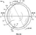
FIG. 2A is a top view of the shell ofFIG. 1 . -
FIGS. 2B and 2C are cross-sectional views of the shell ofFIG. 1 along thelines 2B-2B and 2C-2C shown inFIG. 2A . -
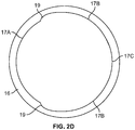
FIG. 2D is a top view of an annular rim of the shell ofFIG. 1 . -
FIG. 3A illustrates a top view of an assembly of the shell ofFIG. 1 and an insert disposed therein in accordance with an embodiment of the disclosure. -
FIG. 3B illustrates an advancement step of the assembly ofFIG. 3A alonglines 3B-3B. -
FIG. 4A is a top view of the assembly ofFIG. 3A in which the insert is rotated to final insertion position. -
FIG. 4B is a cross-sectional view of the assembly ofFIG. 3A alonglines 4B-4B shown inFIG. 4A . -
FIG. 5 is a perspective view of the assembly shown inFIG. 3A in the position shown inFIG. 4A . -
FIG. 6 is a top view of a shell in accordance with another embodiment of the disclosure. -
FIG. 7 is a cross-sectional view of an assembly having the shell ofFIG. 1 and a femoral implant disposed therein in accordance with another embodiment of the disclosure. - The present invention relates to improvements in the securement of elements in ball-and-socket joints, and in particular to multiple bearing joints such as modular dual mobility (MDM) joints. Although many embodiments described herein reference the hip joint, explanation of the invention in such context is non-limiting, and it is contemplated and to be understood that the invention can be used in other joints, such as but not limited to shoulder, elbow, wrist, and finger joints and in other contexts more generally.
- Referring now to the drawings, as shown in
FIGS. 1-5 ,shell 10 is a prosthetic device. More particularly, as shown,shell 10 is a liner which has anexterior surface 13 that, in some arrangements, may be used for placement into an acetabular cup and an interior surface described further herein for holding an insert, such asinsert 20, for a femoral stem (FIG. 3A ). As shown inFIG. 2A ,shell 10 is symmetrical aboutplane 8.Plane 8 bisectsshell 10 at a section as shown inFIG. 2B . As shown inFIGS. 2B and 2C ,shell 10 includes a portion below aplane 9 and another portion aboveplane 9, the latter described herein as exteriorsurface rim depth 13A. The exterior and interior surfaces of the portion belowplane 9 generally define a hemispherical shape. Exteriorsurface rim depth 13A of the portion aboveplane 9 extends fromplane 9 in a generally cylindrical manner toannular end surface 16. The interior surface of the portion aboveplane 9 extending fromplane 9 toannular end surface 16 is partially spherical and partially cylindrical, as seen inFIGS. 2B and 2C and described in greater detail below. - As best shown in
FIGS. 2A-2C , the interior surface ofshell 10 defines a cavity. The interior surface includesfirst portion 12 and symmetricsecond portions 14 extending fromfirst portion 12 of the interior surface. Symmetricsecond portions 14 are symmetrical about plane 8 (FIG. 2A ). The interior surface terminates atinterior edges annular end surface 16.Annular end surface 16 extends around the perimeter ofshell 10 and is bound byexterior edge 18 andinterior edges shell 10. - The shape of
interior edges FIGS. 1 ,2A and2D .Interior edge 17A andinterior edge point 17C (hereinafter also "interior edge 17C") define a portion of a circumference ofcircle 2 with a single radius centered at a location corresponding to a central axis S ofshell 10. Symmetricinterior edges 17B andinterior edge point 17C define a portion of a circumference ofcircle 4, as shown inFIG. 1 , with a single radius centered on a central axis I of a spherically shaped object, in thisexample insert 20, to be inserted intoshell 10, described in greater detail below. The radii ofrespective edges circle 2 is smaller than that ofcircle 4. In the example shown, the radius forinterior edge 17A is set at approximately 0.908 inches, and the radius forinterior edges 17B is set at approximately 0.948 inches. In a preferred arrangement, the radius forinterior edge 17A is set at approximately 0.895 to 0.935 inches, and the radius for symmetricinterior edges 17B is set at approximately 0.948 inches. A relationship exists between an offset 5 of central axis I relative to central axis S and exteriorsurface rim depth 13A. For a given shell withinterior edge 17B radius of 0.948 inches, corresponding axes, offsets and exterior surface rim depths are shown in Table 1 below:TABLE 1 Shell with a maximum interior edge radius of 0.948 inches Minimum interior edge radius (inches) 0.935 0.928 0.919 0.908 0.895 Offset of central axis I relative to central axis S (inches) 0.013 0.020 0.029 0.040 0.053 Exterior surface rim depth (inches) 0.164 0.203 0.243 0.281 0.321 - As demonstrated by Table 1, a shell with a larger or smaller maximum interior edge radius is contemplated that will also have increasing exterior surface rim depth corresponding to increasing offset between the central axes (i.e., I and S). The relationship between offset 5 and exterior
surface rim depth 13A is scalable and not limited to a shell with a maximum interior edge radius of 0.948 inches as shown above. The values described in Table 1 may vary within a range limited at one extreme by a maximum amount of material removed from the interior surface of the shell and at the other extreme, by the minimum amount of material removed from symmetricsecond portions 14 relative tofirst portion 12 and proximal tojunctures 19 necessary to create an interior edge with a perimeter sufficient in cross-sectional area for an insert to be advanced therein. - Further, and as shown in
FIG. 1 , central axis I is offset from central axis S so that the circumferences of the respective circles centered on central axes I and S are tangential atinterior edge point 17C. In this way,circle 2 is entirely disposed withincircle 4 except atinterior edge 17C. As will be described in greater detail below, this geometry facilitates the advancement and constraint of an object within the cavity ofshell 10. - First and symmetric
second portions interior edges FIGS. 2A-2C .First portion 12 of the interior surface abutsinterior edges FIG. 2B .First portion 12 of the interior surface is concave in shape in all directions, as best shown in the cross-sectional views ofFIGS. 2B and 2C . In particular, the interior surface offirst portion 12 forms a partial spherical shape slightly larger than an outer surface of a partially spherical insert to accommodate insertion of the insert into the cavity. Symmetricsecond portions 14 of the interior surface abutinterior edges FIG. 2C in particular, a surface of eachsecond portion 14 of the interior surface is perpendicular to a plane defined byannular end surface 16. -
Junctures 19 are located at interfaces betweeninterior edges 17B andinterior edge 17A as seen inFIG. 2A , and have a length fromannular edge surface 16 to a depth within the cavity ofshell 10 that is belowplane 9, corresponding to afirst point 15A, as best shown inFIG. 2B . - The interior surface of
shell 10 includessteps 15 at an interface betweensecond portion 14 andfirst portion 12 and located at a maximum depth ofsecond portion 14, at a furthest extent fromannular end surface 16, as shown inFIGS. 2B and 2C .Steps 15 are symmetrical aboutplane 8, as shown inFIG. 2A . For ease of explanation, the geometry of one step is described below, but it is understood that the same geometry exists on the opposite side ofshell 10. In some arrangements, step 15 may be formed by an indent intofirst portion 12. As in the example illustrated,step 15 may have a finite length parallel to endsurface 16 extending fromfirst point 15A to asecond point 15B. - Returning to the geometry of symmetric
second portions 14, fromsecond point 15B toward the point at interior edge point 17C, the depth ofsecond portion 14 lessens until terminating at interior edge point 17C, as best shown inFIGS. 2B and 2C . In this manner, a part of the interior edge at an end of symmetricsecond portions 14opposite juncture 19 is abutted by the first portion (i.e., atinterior edge 17C). Thus, each of symmetricsecond portions 14 of the interior surface are separated on all edges within the cavity byfirst portion 12. Described another way, symmetricinterior edges 17B both extend tointerior edge 17A at one end andinterior edge point 17C at an opposite end. An approximate demarcation of eachinterior edge FIG. 2D where points are included on the interior edge ofannular end surface 16 to highlight the separation of each. The points identify the location ofjunctures 19 andinterior edge point 17C for symmetricsecond portions 14 of the interior surface. - Continuing to refer to
FIGS. 2B and 2C ,first portion 12 of the interior surface ofshell 10 forms an acute angle withannular end surface 16 atinterior edges second portions 14 of the interior surface form a right angle withannular end surface 16 atinterior edges 17B. Described another way, the interior surface ofshell 10 is partially spherical (first portion 12) with a partially cylindrical cutout (symmetric second portions 14) in which the center of the cylindrical cutout is offset from the center of the partially spherical surface. The depth of the cylindrical cutout is only partway into a depth of the interior surface, as seen inFIGS. 2A-2C . - In some arrangements,
shell 10 is combined with a cup-shaped implant, such as an acetabular cup (not shown), to form an acetabular cup assembly.Exterior surface 13 ofshell 10 is dimensioned to correspond to an interior surface of an acetabular cup sized for placement in the acetabulum of a patient. In some such arrangements,shell 10 rotates within the acetabular cup, providing a dual mobility (i.e., MDM) function when combined with additional elements as described in greater detail below. - Referring now to
FIGS. 3A-5 , the acetabular cup assembly described immediately above is combined with aprosthetic insert 20 into which a ball joint on a stem (not shown), such as but not limited to a ball joint of a femoral stem implant, may be inserted.Insert 20 is dimensioned for insertion intoshell 10, and the stem is dimensioned to fit within a cavity defined byinterior surface 22 ofinsert 20.Insert 20 includes a partially sphericalexternal surface 28 and aflat end surface 26 which truncates the partially spherical surface.Interior surface 22 extends fromflat end surface 26. In this manner, the stem extending from the ball joint may be articulated within the cavity defined byinterior surface 22 when ball joint is inserted intoinsert 20. -
Insert 20 is dimensioned such that when aligned and oriented in a particular manner relative to shell 10, the insert can be advanced into the cavity of the shell through each of symmetricsecond portions 14 of the interior surface ofshell 10. As shown inFIG. 3A , insert 20 must be positioned with a plane defined byflat end surface 26 normal to the plane defined byannular end surface 16 and withflat end surface 26 aligned withjunctures 19 of symmetricsecond portions 14 for advancement intoshell 10. In this position, a portion offlat end surface 26 betweenjunctures 19 facefirst portion 12 of interior surface. The components as described, when combined, form a system which provides a dual mobility function. As such,shell 10 is rotatable and articulable within an acetabular cup, and, independently ofshell 10, insert 20 is rotatable and articulable inshell 10 when inserted therein. - Material for
shell 10 is any known to the ordinary artisan for socket elements used as part of a ball-and-socket joint. In the embodiments described herein, the insert is made of a polymer, which may be but is not limited to being ultra high molecular-weight polyethylene (UHMWPE), PEEK or polyurethane. In variants, the insert may be made of a ceramic, metal, such as but not limited to CoCr, or mixtures thereof, such as ceramicized metal. In further variants, other materials can be used as deemed suitable for desired applications. - In accordance with another aspect of the disclosure, elements of
assembly 30 are used in a method of fabrication. Referring toFIGS. 3A-5 , in one example of fabricatingassembly 30, insert 20 is provided external to shell 10.Insert 20 is then oriented such that itsflat end surface 26 is perpendicular toannular end surface 16 ofshell 10. In this manner, whenflat end surface 26 ofinsert 20 is also positioned offset from center S ofshell 10, as best shown inFIG. 3B ,flat end surface 26 ofinsert 20 is aligned in a plane passing through both symmetricalsecond portions 14 of the interior surface. When aligned and oriented as described, insert 20 is advanced into the cavity ofshell 10, as shown inFIGS. 3A and 3B . In this example, insert 20 is receivable inshell 10 in the orientation shown, but not in other orientations, such as an orientation orthogonal to that shown. During advancement, the orientation ofinsert 20 is maintained (seeFIG. 3B ). Whenexternal surface 28 ofinsert 20 contacts or is otherwise proximal to a bottom offirst portion 12 of the interior surface at a maximum depth fromannular end surface 16 ofshell 10, as shown inFIG. 3B , advancement ofinsert 20 is complete. In this position,external surface 28 ofinsert 20 roughly corresponds to the interior surface ofshell 10, but as seen inFIG. 3B ,variable gap 41 is formed between the external surface of the insert and the interior surface of the shell when the insert is fully advanced.Gap 41 increases as the circumferential distance fromflat end surface 26 ofinsert 20 increases. - Upon completion of advancement of
insert 20, the insert is rotated such that a majority ofexternal surface 28 corresponds to one of thefirst portion 12 orsecond portion 14 of the interior surface, as shown inFIG. 4B . In one example, insert 20 is rotated ninety degrees.Insert 20 is rotated following advancement with little or no translation and is rotated about an axis 7 (shown inFIG. 3B ) through its center and parallel toflat end surface 26. Ifinsert 20 was attempted to be rotated about another axis to rotateflat end surface 26,symmetric junctures 19 would impede and otherwise block any rotation from the fully inserted position shown inFIGS. 3A and 3B . When it is fully advanced and fully rotated, insert 20 sits proud ofshell 10 as shown inFIGS. 4B and5 . Again with reference toFIG. 4B , wheninsert 20 is fully advanced and fully rotated inshell 10, insert 20 is constrained by the shell asfirst portion 12 of the interior surface proximal tointerior edges shell 10 and over an edge at a maximum diameter ofinsert 20. - The close correspondence between surfaces of
insert 20 andshell 10 provides additional protection against disengagement ofinsert 20. Because symmetricsecond portions 14 of the interior surface ofshell 10 are lesser in depth closer tointerior edge point 17C on one end of each of these portions and are separated from each other byfirst portion 12 on the other end of each of these portions, as shown inFIGS. 2B and 2C , inward facing interior surfaces offirst portion 12 exist on opposite sides of a plane ofshell 10 drawn betweenjunctures 19 of symmetricsecond portions 14. In this manner, insert 20 is additionally constrained. - With
insert 20 secured withinshell 10, a ball joint on a stem (not shown) is inserted into the cavity ofinsert 20. In turn, the stem is then inserted into a bone, such as but not limited to a femur. The geometry of the shell and its interior surface optimizes the range of motion of an insert disposed therein. For example, because the fully advanced and fully rotated insert sits proud of the shell, the prosthetic stem disposed in the insert can be rotated over a wide range of angles compared to devices known in the art as the stem is not constrained by a surface of the shell extending above an end surface of the insert. The degree to which the stem can be rotated is a function of at least the diameter of the stem, the exterior surface rim depth of the shell and the width of the annular end surface of the shell. For example, if the exterior surface rim depth of the shell increases, the angle to which the stem may be rotated decreases. In this manner, the stem can be articulated, i.e., swiveled, up to approximately 180 degrees relative to a longitudinal axis through a center of the device opening (i.e., centerline S axis, as best shown inFIG. 3B ), and preferably at least approximately 120 degrees. - The prosthetic device (e.g., shell), assembly, system and fabrication method may be varied in many respects. In some examples, a curved exterior (and/or interior) surface of the prosthetic device can be ellipsoidal or otherwise ovular in nature. In other examples, a cross-section of an end surface of the prosthetic device can be square, rectangular, or ovular, among other shapes. For any given prosthetic device, the end surface and curved surface may be any combination of these or other shapes. In at least some arrangements, part of an interior surface of the prosthetic device is defined by a second radius shaped to accommodate advancement of the insert and includes a center offset from a center of a first radius the prosthetic device. For example, where the external curved surface of the device is ellipsoidally shaped, the device may include a cavity with a corresponding ellipsoidal shape, separated from the external shape by an end surface. The end surface in this example may be ellipsoidal or another shape. The interior surface may include a concave portion and another portion indented relative to the concave portion. The concave portion may have a radius smaller than that of the indented portion, and a center from which the radius of the concave portion is measured may be offset from a center of the radius for the indented portion.
- As shown in
FIG. 6 , in another arrangement, ashell 110 includesinterior edges 117A-1, 117A-2 defined by a portion of a circumference of asmaller circle 102, andinterior edges 117B defined by a portion of a circumference of alarger circle 104.Smaller circle 102 overlaps withlarger circle 104 atpoints 117C-1 and 117C-2. As with the embodiments described above, a center S-2 ofcircle 102 is offset from a center I-2 ofcircle 104. The overlap betweencircles interior edges 117A-1, 117A-2.Interior edge 117A-1 extends between opposingjunctures 119 whileinterior edge 117A-2 extends betweenpoints 117C-1 and 117C-2 such thatinterior edge 117B extends between one ofjunctures 119 and one ofpoints 117C-1 and 117C-2. An interior surface ofshell 110 includes afirst portion 112 and a second portion (not shown) as described in the embodiments described previously herein. - In some examples, the prosthetic device may be configured to function both as an acetabular cup and a liner for an insert, thus removing the need for an additional element between the prosthetic device and the acetabulum when implanted in a patient. In another example, the cup-shaped implant, e.g., acetabular cup, may include a locking mechanism, such as but not limited to a morse taper, that corresponds to a feature on the prosthetic device such that when combined, the cup-shaped implant and the prosthetic device are fixed and do not rotate relative to one another. In other examples, the insert may be a femoral head monolithic with, and thus inseparable from, a stem. In other embodiments, the prosthetic device may be configured and shaped for use in locations of the body other than the hip, for example, in the shoulder, elbow, wrist or finger.
- As shown in
FIG. 7 , in some embodiments, retainingring 225, which as in the example shown may be a plastic slotted ring surrounded by an internal wire, is positioned alonginner groove 222 ofinsert 220. Retainingring 225 slides inward and away from an opening ofinsert 220 asfemoral head 250 is advanced intoinsert 220 and against the retaining ring, expanding the retaining ring and minimizing the force necessary for advancement of the insert. Whenfemoral head 250 is fully advanced intoinsert 220 with a maximum diameter of the femoral head past retainingring 225, the retaining ring contracts to a smaller diameter and returns toward its initial position proximate the opening ofinsert 220, as shown inFIG. 7 . In this manner, retainingring 225 securesfemoral head 250 in position withininsert 220 and thus allows the femoral head to be advanced into the insert by hand without resistance from the insert and thus without any tools. In employing this assembly, insert 220 can be inserted intoshell 10 first, then rotated into a secure position, in a manner similar to that shown forinsert 20 inFIGS. 3B and4B , and thenfemoral head 250 and stem 260 inserted into and extending from the head can be inserted separately thereafter. An applicable variant of such assembly of a femoral head to an insert using a locking ring is described in Trident Constrained Acetabular Insert: Surgical Protocol, by Stryker, copyright 2012, hereby incorporated by reference herein in its entirety. In other embodiments, the interior surface of the insert does not include a retaining ring. Examples of such a configuration are shown inFIG. 3B and in MDM X3: Surgical Technique by Stryker, copyright 2012, hereby incorporated by reference herein in its entirety. - In still further arrangements, the interior surface of the shell may include a single second portion indented relative to a first portion such that an entire interior surface of the shell includes only one first portion and only one second portion. In these arrangements, the second portion may include geometric features as described above. Of course, the features described in the various examples and embodiments herein are contemplated as being configured for use in combination with one another. In addition, it is contemplated that the methods of the present disclosuremay be employed using the various alternative embodiments described.
- In some arrangements, after fabricating a prosthetic assembly such as
assembly 30, the combined insert and shell may be advanced into a cup-shaped implant, such as an acetabular cup. Alternatively, the shell may be advanced into the acetabular cup prior to advancement of the insert into the shell. In any of the above embodiments, a prosthetic stem may be inserted into the insert. At any point prior to assembly with the shell, the acetabular cup may be inserted into an acetabulum of a patient. Where the shell is disposed in an acetabular cup, the combined system provides dual mobility functionality, as described above. - Although the invention herein has been described with reference to particular embodiments, it is to be understood that these embodiments are merely illustrative of the principles and applications of the present invention. It is therefore to be understood that numerous modifications may be made to the illustrative embodiments and that other arrangements may be devised.
Claims (12)
- A prosthetic device (10) comprising:an exterior surface (13);an interior surface (12, 14), the interior surface (12, 14) having first and second portions (12, 14); andan end surface (16) having exterior and interior edges (18, 17A, 17B, 17C) and extending between the exterior (13) and the interior surfaces (12, 14),wherein the second portion (14) of the interior surface (12, 14) extends from the interior edge (17B) of the end surface (16) at a right angle relative to the end surface (16), andwherein the second portion (14) includes a step (15) that abuts the first portion (12).
- The prosthetic device of claim 1, wherein the second portion (14) of the interior surface (12, 14) has a depth extending from the interior edge (17A, 17B, 17C) of the end surface (16) to a location at or below a maximum width of the interior surface measured in a plane (9) parallel to the end surface (16).
- The prosthetic device of any one of claims 1 and 2, wherein the first portion (12) of the interior surface (12, 14) extends from the interior edge (17A, 17C) of the end surface (16) at an acute angle relative to the end surface (16) at one or more locations of the first portion (12).
- The prosthetic device of any one of claims 1 to 3, wherein the end surface (16) includes a width measured between the exterior (18) and interior edges (17A, 17B, 17C) such that the width at one or more locations of the end surface (16) abutting the second portion (14) of the interior surface (12, 14) is narrower than the width abutting the first portion (12) of the interior surface (12, 14).
- The prosthetic device of any one of claim 1 to 4, wherein the interior surface (12, 14) includes a third portion (14) that shares an interior edge with the first portion (12), and
wherein the second and the third portions (14) include locations at maximum distances from a central axis of the first portion (12) that is perpendicular to a plane defined by the end surface (16), wherein the locations at maximum distances lie along a maximum separation axis offset from or at an angle to a first central plane (9) through the interior surface (12, 14). - The prosthetic device of claim 5, wherein the second and third portions (14) of the interior surface (12, 14) are separated by the first portion (12).
- The prosthetic device of any one of claims 5 and 6, wherein the maximum separation axis is parallel to the first central plane (9).
- The prosthetic device of claim 7, wherein the second and third portions (14) of the interior surface (12, 14) are symmetrical about a second central plane through the interior surface (12, 14) normal to the first central plane (9).
- The prosthetic device of any one of claims 5 to 8, wherein the second and third portions (14) include indentations such that a partially spherical insert (20, 220) having a substantially flat end surface (26) on a side thereof is insertable into the prosthetic device (10) only when the substantially flat end surface (26) is positioned between the second and the third portions (14) of the interior surface (12, 14).
- A prosthesis system comprising:a cup-shaped implant;a prosthetic device (10) comprising:an exterior surface (13);an interior surface (12, 14) defining a cavity; andan end surface (16) having exterior and interior edges (18, 17A, 17B, 17C) and extending between the exterior (13) and the interior surfaces (12, 14), the interior edge (17A, 17B, 17C) of the end surface (16) being defined at least in part by (i) a first curved portion (12) having a first radius and (ii) a second curved portion (14) having a second radius different from that of the first curved portion (12),wherein a radial center (S) of the first curved portion (12) is offset from a radial center (I) of the second curved portion (14) such that a circumference (2) defined by the first radius is entirely within a circumference (4) defined by the second radius, andwherein the prosthetic device (10) is receivable in the cup-shaped implant;an insert (20, 220) receivable in the prosthetic device (10); anda prosthetic component having a stem (260) attached to a ball joint (250) receivable in the insert (20, 220).
- The prosthesis system of claim 10, wherein the insert (20, 220) is receivable in the prosthetic device (10) in a first orientation relative to the prosthetic device (10) and not receivable in the prosthetic device (10) in a second orientation orthogonal to the first direction.
- The prosthesis system of claim 11, wherein the first orientation aligns a curved surface (28) of the insert (20, 220) with the second curved portion (17B) and the flat surface (26) of the insert in a direction facing the first curved portion (17A).
Applications Claiming Priority (1)
| Application Number | Priority Date | Filing Date | Title |
|---|---|---|---|
| US201762453733P | 2017-02-02 | 2017-02-02 |
Publications (3)
| Publication Number | Publication Date |
|---|---|
| EP3391858A2 true EP3391858A2 (en) | 2018-10-24 |
| EP3391858A3 EP3391858A3 (en) | 2018-11-21 |
| EP3391858B1 EP3391858B1 (en) | 2020-04-01 |
Family
ID=61132279
Family Applications (1)
| Application Number | Title | Priority Date | Filing Date |
|---|---|---|---|
| EP18154625.0A Active EP3391858B1 (en) | 2017-02-02 | 2018-02-01 | Constrained shell for modular dual mobility system |
Country Status (3)
| Country | Link |
|---|---|
| US (1) | US11033395B2 (en) |
| EP (1) | EP3391858B1 (en) |
| AU (1) | AU2018200701B2 (en) |
Families Citing this family (5)
| Publication number | Priority date | Publication date | Assignee | Title |
|---|---|---|---|---|
| US11376128B2 (en) * | 2018-12-31 | 2022-07-05 | Depuy Ireland Unlimited Company | Acetabular orthopaedic prosthesis and method |
| US11419729B2 (en) | 2019-06-20 | 2022-08-23 | Northwell Health, Inc. | Constrained acetabular liner |
| US12150859B2 (en) * | 2020-07-20 | 2024-11-26 | Joint Development, Inc. | Dual mobility acetabular component |
| US12083018B2 (en) | 2020-09-18 | 2024-09-10 | Globus Medical, Inc. | Hip arthroplasty implants |
| US12053383B2 (en) | 2020-09-18 | 2024-08-06 | Globus Medical Inc. | Hip arthroplasty implants |
Family Cites Families (38)
| Publication number | Priority date | Publication date | Assignee | Title |
|---|---|---|---|---|
| DE2829676A1 (en) | 1978-07-06 | 1980-01-24 | Gmt Medizinische Technik Gmbh | ENDOPROTHESIS |
| FR2516377A1 (en) | 1981-11-13 | 1983-05-20 | Breard Francis | Artificial hip joint socket - has external face joined to cavity wall by spherical sector with grooved outer surface |
| US4437193A (en) | 1982-01-18 | 1984-03-20 | Indong Oh | Protrusio cup |
| US5879399A (en) | 1982-04-07 | 1999-03-09 | British Technology Group Ltd. | Endoprosthetic bone joint devices |
| EP0091315B1 (en) | 1982-04-07 | 1986-07-30 | National Research Development Corporation | Endoprosthetic bone joint devices |
| DE9312151U1 (en) | 1992-08-17 | 1994-06-16 | Murrplastik Systemtechnik GmbH, 71570 Oppenweiler | Quick coupling for hoses |
| ATE161704T1 (en) | 1992-09-01 | 1998-01-15 | Sulzer Orthopaedie Ag | DOUBLE-SHELF REVISION HIP JOINT CUP |
| US5383938A (en) | 1993-02-12 | 1995-01-24 | Zimmer, Inc. | Locking ring for an acetabular cup |
| US5725587A (en) | 1995-12-14 | 1998-03-10 | Zimmer, Inc. | Acetabular cup assembly |
| US5782930A (en) | 1996-02-13 | 1998-07-21 | Hommedica Inc. | Polyetheretherketone (PEEK) retaining ring for an acetabular cup assembly |
| US5916270A (en) | 1997-06-06 | 1999-06-29 | New York Society For The Ruptured And Crippled Maintaining The Hospital For Special Surgery | Hip replacement |
| FR2770769B1 (en) * | 1997-11-07 | 2000-02-18 | Orthotechnique | ACETABULAR COMPONENT |
| FR2771922B1 (en) | 1997-12-08 | 2000-03-10 | Christophe Cermolacce | INSERT AND COTYLOID CUP FOR HIP PROSTHESIS |
| FR2785525B1 (en) | 1998-11-10 | 2001-01-19 | Rech S Et De Fabrication S E R | SPHERICAL HEAD OF A FEMALE HIP PROSTHESIS, INTENDED TO BE ENGAGED IN A CUP OF SYNTHETIC MATERIAL |
| FR2795302B1 (en) | 1999-06-23 | 2001-12-28 | Rech S Et De Fabrication S E R | TOTAL HIP PROSTHESIS |
| KR20020083166A (en) | 2000-03-14 | 2002-11-01 | 스미스 앤드 네퓨, 인크. | Variable Geometry Rim Surface Acetabular Shell Liner |
| US7682398B2 (en) | 2000-03-14 | 2010-03-23 | Smith & Nephew, Inc. | Variable geometry rim surface acetabular shell liner |
| FR2807315B1 (en) | 2000-04-06 | 2003-01-17 | Rech S Et De Fabrication S E R | COTYLOID INSERT FOR TOTAL HIP PROSTHESIS |
| DE10036987A1 (en) | 2000-07-29 | 2002-02-07 | Klaus Draenert | Modular pan replacement |
| US6626947B2 (en) | 2000-10-03 | 2003-09-30 | Depuy Orthopaedics, Inc. | Press fit acetabular cup and associated method for securing the cup to an acetabulum |
| ATE387161T1 (en) | 2001-01-25 | 2008-03-15 | Smith & Nephew Inc | RETAINING DEVICE FOR HOLDING A PROSTHETIC COMPONENT |
| GB0117578D0 (en) | 2001-07-19 | 2001-09-12 | Zarlink Semiconductor Ltd | Tuner |
| EP1411868A4 (en) | 2001-07-31 | 2006-04-12 | Biomet Inc | Method and apparatus for use of a metal-metal constrained liner |
| DE10304102A1 (en) | 2003-01-31 | 2004-08-12 | Ceram Tec Ag Innovative Ceramic Engineering | hip prosthesis |
| EP1520559A1 (en) | 2003-09-30 | 2005-04-06 | Technische Universität München | Acetubular liner |
| GB0407624D0 (en) | 2004-04-02 | 2004-05-05 | Benoist Girard Sas | Prosthetic femoral joint |
| GB0521406D0 (en) * | 2005-10-20 | 2005-11-30 | Benoist Girard Sas | Total hip prosthesis |
| US7708783B2 (en) | 2005-11-04 | 2010-05-04 | Zimmer Technology, Inc. | Rotating constrained liner |
| FR2929103B1 (en) | 2008-03-26 | 2010-04-02 | Scor Group | COTYLOID PROSTHESIS OF THE TYPE DIT "DOUBLE MOBILITY" |
| EP2451389B1 (en) | 2009-07-10 | 2015-08-19 | Kirk Promotion LTD. | Hip joint device |
| FR2951071B1 (en) | 2009-10-12 | 2011-10-28 | Thomas Gradel | PROTHETIC COTYLE WITH LARGE RETENTION CAPACITY |
| US8465549B2 (en) | 2011-02-16 | 2013-06-18 | Rodney Ian Walter Richardson | Acetabular cup with rotatable bearing |
| US8398718B2 (en) | 2011-02-16 | 2013-03-19 | Rodney Ian Walter Richardson | Acetabular cup with rotatable bearing member |
| US9023112B2 (en) | 2011-02-24 | 2015-05-05 | Depuy (Ireland) | Maintaining proper mechanics THA |
| US9060862B2 (en) | 2011-07-08 | 2015-06-23 | Floyd Franklin Castro | Semi-constrained ball and socket joints |
| US8771366B2 (en) | 2012-03-30 | 2014-07-08 | DePuy Synthes Products, LLC | Mobile bearing hip assembly having decoupled motion along multiple axes |
| CA2894769C (en) | 2012-12-18 | 2021-06-15 | Bispebjerg Hospital | Medical implant for reducing pain in diseased joints |
| US20160250027A1 (en) | 2015-02-27 | 2016-09-01 | The Curators Of The University Of Missouri | System and method for improved constrained prosthetic acetabulum |
-
2018
- 2018-01-30 AU AU2018200701A patent/AU2018200701B2/en active Active
- 2018-02-01 US US15/886,235 patent/US11033395B2/en active Active
- 2018-02-01 EP EP18154625.0A patent/EP3391858B1/en active Active
Non-Patent Citations (1)
| Title |
|---|
| None |
Also Published As
| Publication number | Publication date |
|---|---|
| EP3391858B1 (en) | 2020-04-01 |
| EP3391858A3 (en) | 2018-11-21 |
| AU2018200701B2 (en) | 2023-07-27 |
| AU2018200701A1 (en) | 2018-08-16 |
| US11033395B2 (en) | 2021-06-15 |
| US20180214274A1 (en) | 2018-08-02 |
Similar Documents
| Publication | Publication Date | Title |
|---|---|---|
| EP3391858B1 (en) | Constrained shell for modular dual mobility system | |
| EP1133958B1 (en) | Prosthetic cup assembly which includes components possessing self-locking taper | |
| JP6069756B2 (en) | Acetabular cup with rotatable bearing | |
| EP3405141B1 (en) | Constrained dual mobility hip prosthesis | |
| US10307255B1 (en) | Acetabular cup assembly | |
| CA2471779C (en) | Constrained acetabular liner | |
| EP1776934B1 (en) | Total hip prosthesis | |
| AU2004210449B2 (en) | Cotyloid implant for a hip prosthesis | |
| JP5911095B2 (en) | Acetabular cup with rotatable bearing member | |
| EP1377237B1 (en) | Containment system for constraining a prosthetic component | |
| EP1522282A2 (en) | Hip prosthesis with a modular acetabular cup assembly | |
| US6379389B1 (en) | Artificial hip joint socket | |
| US12121450B2 (en) | Reverse shoulder prosthesis | |
| EP2844194B1 (en) | Variable angle reverse humeral tray | |
| CN113507903B (en) | Acetabular devices for hip revision surgery | |
| CN112294500B (en) | Wrist joint prosthesis | |
| EP3242634B1 (en) | Liner system | |
| WO2005039453A1 (en) | Acetabular liner | |
| US10898338B1 (en) | Reverse shoulder prosthesis | |
| EP4400082B1 (en) | Inverse shoulder prosthesis with improved glenosphere | |
| KR101575157B1 (en) | Artificial Shoulder Joint | |
| US20080033564A1 (en) | Artificial Joint |
Legal Events
| Date | Code | Title | Description |
|---|---|---|---|
| PUAI | Public reference made under article 153(3) epc to a published international application that has entered the european phase |
Free format text: ORIGINAL CODE: 0009012 |
|
| STAA | Information on the status of an ep patent application or granted ep patent |
Free format text: STATUS: THE APPLICATION HAS BEEN PUBLISHED |
|
| PUAL | Search report despatched |
Free format text: ORIGINAL CODE: 0009013 |
|
| AK | Designated contracting states |
Kind code of ref document: A2 Designated state(s): AL AT BE BG CH CY CZ DE DK EE ES FI FR GB GR HR HU IE IS IT LI LT LU LV MC MK MT NL NO PL PT RO RS SE SI SK SM TR |
|
| AX | Request for extension of the european patent |
Extension state: BA ME |
|
| AK | Designated contracting states |
Kind code of ref document: A3 Designated state(s): AL AT BE BG CH CY CZ DE DK EE ES FI FR GB GR HR HU IE IS IT LI LT LU LV MC MK MT NL NO PL PT RO RS SE SI SK SM TR |
|
| AX | Request for extension of the european patent |
Extension state: BA ME |
|
| RIC1 | Information provided on ipc code assigned before grant |
Ipc: A61F 2/32 20060101ALI20181017BHEP Ipc: A61F 2/34 20060101AFI20181017BHEP |
|
| STAA | Information on the status of an ep patent application or granted ep patent |
Free format text: STATUS: REQUEST FOR EXAMINATION WAS MADE |
|
| 17P | Request for examination filed |
Effective date: 20190521 |
|
| GRAP | Despatch of communication of intention to grant a patent |
Free format text: ORIGINAL CODE: EPIDOSNIGR1 |
|
| STAA | Information on the status of an ep patent application or granted ep patent |
Free format text: STATUS: GRANT OF PATENT IS INTENDED |
|
| INTG | Intention to grant announced |
Effective date: 20191104 |
|
| GRAS | Grant fee paid |
Free format text: ORIGINAL CODE: EPIDOSNIGR3 |
|
| GRAA | (expected) grant |
Free format text: ORIGINAL CODE: 0009210 |
|
| STAA | Information on the status of an ep patent application or granted ep patent |
Free format text: STATUS: THE PATENT HAS BEEN GRANTED |
|
| AK | Designated contracting states |
Kind code of ref document: B1 Designated state(s): AL AT BE BG CH CY CZ DE DK EE ES FI FR GB GR HR HU IE IS IT LI LT LU LV MC MK MT NL NO PL PT RO RS SE SI SK SM TR |
|
| REG | Reference to a national code |
Ref country code: GB Ref legal event code: FG4D |
|
| REG | Reference to a national code |
Ref country code: AT Ref legal event code: REF Ref document number: 1250393 Country of ref document: AT Kind code of ref document: T Effective date: 20200415 Ref country code: CH Ref legal event code: EP |
|
| REG | Reference to a national code |
Ref country code: DE Ref legal event code: R096 Ref document number: 602018003315 Country of ref document: DE |
|
| REG | Reference to a national code |
Ref country code: IE Ref legal event code: FG4D |
|
| PG25 | Lapsed in a contracting state [announced via postgrant information from national office to epo] |
Ref country code: BG Free format text: LAPSE BECAUSE OF FAILURE TO SUBMIT A TRANSLATION OF THE DESCRIPTION OR TO PAY THE FEE WITHIN THE PRESCRIBED TIME-LIMIT Effective date: 20200701 |
|
| REG | Reference to a national code |
Ref country code: NL Ref legal event code: MP Effective date: 20200401 |
|
| REG | Reference to a national code |
Ref country code: LT Ref legal event code: MG4D |
|
| PG25 | Lapsed in a contracting state [announced via postgrant information from national office to epo] |
Ref country code: NL Free format text: LAPSE BECAUSE OF FAILURE TO SUBMIT A TRANSLATION OF THE DESCRIPTION OR TO PAY THE FEE WITHIN THE PRESCRIBED TIME-LIMIT Effective date: 20200401 Ref country code: IS Free format text: LAPSE BECAUSE OF FAILURE TO SUBMIT A TRANSLATION OF THE DESCRIPTION OR TO PAY THE FEE WITHIN THE PRESCRIBED TIME-LIMIT Effective date: 20200801 Ref country code: CZ Free format text: LAPSE BECAUSE OF FAILURE TO SUBMIT A TRANSLATION OF THE DESCRIPTION OR TO PAY THE FEE WITHIN THE PRESCRIBED TIME-LIMIT Effective date: 20200401 Ref country code: FI Free format text: LAPSE BECAUSE OF FAILURE TO SUBMIT A TRANSLATION OF THE DESCRIPTION OR TO PAY THE FEE WITHIN THE PRESCRIBED TIME-LIMIT Effective date: 20200401 Ref country code: SE Free format text: LAPSE BECAUSE OF FAILURE TO SUBMIT A TRANSLATION OF THE DESCRIPTION OR TO PAY THE FEE WITHIN THE PRESCRIBED TIME-LIMIT Effective date: 20200401 Ref country code: GR Free format text: LAPSE BECAUSE OF FAILURE TO SUBMIT A TRANSLATION OF THE DESCRIPTION OR TO PAY THE FEE WITHIN THE PRESCRIBED TIME-LIMIT Effective date: 20200702 Ref country code: NO Free format text: LAPSE BECAUSE OF FAILURE TO SUBMIT A TRANSLATION OF THE DESCRIPTION OR TO PAY THE FEE WITHIN THE PRESCRIBED TIME-LIMIT Effective date: 20200701 Ref country code: LT Free format text: LAPSE BECAUSE OF FAILURE TO SUBMIT A TRANSLATION OF THE DESCRIPTION OR TO PAY THE FEE WITHIN THE PRESCRIBED TIME-LIMIT Effective date: 20200401 Ref country code: PT Free format text: LAPSE BECAUSE OF FAILURE TO SUBMIT A TRANSLATION OF THE DESCRIPTION OR TO PAY THE FEE WITHIN THE PRESCRIBED TIME-LIMIT Effective date: 20200817 |
|
| REG | Reference to a national code |
Ref country code: AT Ref legal event code: MK05 Ref document number: 1250393 Country of ref document: AT Kind code of ref document: T Effective date: 20200401 |
|
| PG25 | Lapsed in a contracting state [announced via postgrant information from national office to epo] |
Ref country code: LV Free format text: LAPSE BECAUSE OF FAILURE TO SUBMIT A TRANSLATION OF THE DESCRIPTION OR TO PAY THE FEE WITHIN THE PRESCRIBED TIME-LIMIT Effective date: 20200401 Ref country code: RS Free format text: LAPSE BECAUSE OF FAILURE TO SUBMIT A TRANSLATION OF THE DESCRIPTION OR TO PAY THE FEE WITHIN THE PRESCRIBED TIME-LIMIT Effective date: 20200401 Ref country code: HR Free format text: LAPSE BECAUSE OF FAILURE TO SUBMIT A TRANSLATION OF THE DESCRIPTION OR TO PAY THE FEE WITHIN THE PRESCRIBED TIME-LIMIT Effective date: 20200401 |
|
| PG25 | Lapsed in a contracting state [announced via postgrant information from national office to epo] |
Ref country code: AL Free format text: LAPSE BECAUSE OF FAILURE TO SUBMIT A TRANSLATION OF THE DESCRIPTION OR TO PAY THE FEE WITHIN THE PRESCRIBED TIME-LIMIT Effective date: 20200401 |
|
| REG | Reference to a national code |
Ref country code: DE Ref legal event code: R097 Ref document number: 602018003315 Country of ref document: DE |
|
| PG25 | Lapsed in a contracting state [announced via postgrant information from national office to epo] |
Ref country code: DK Free format text: LAPSE BECAUSE OF FAILURE TO SUBMIT A TRANSLATION OF THE DESCRIPTION OR TO PAY THE FEE WITHIN THE PRESCRIBED TIME-LIMIT Effective date: 20200401 Ref country code: RO Free format text: LAPSE BECAUSE OF FAILURE TO SUBMIT A TRANSLATION OF THE DESCRIPTION OR TO PAY THE FEE WITHIN THE PRESCRIBED TIME-LIMIT Effective date: 20200401 Ref country code: IT Free format text: LAPSE BECAUSE OF FAILURE TO SUBMIT A TRANSLATION OF THE DESCRIPTION OR TO PAY THE FEE WITHIN THE PRESCRIBED TIME-LIMIT Effective date: 20200401 Ref country code: ES Free format text: LAPSE BECAUSE OF FAILURE TO SUBMIT A TRANSLATION OF THE DESCRIPTION OR TO PAY THE FEE WITHIN THE PRESCRIBED TIME-LIMIT Effective date: 20200401 Ref country code: SM Free format text: LAPSE BECAUSE OF FAILURE TO SUBMIT A TRANSLATION OF THE DESCRIPTION OR TO PAY THE FEE WITHIN THE PRESCRIBED TIME-LIMIT Effective date: 20200401 Ref country code: EE Free format text: LAPSE BECAUSE OF FAILURE TO SUBMIT A TRANSLATION OF THE DESCRIPTION OR TO PAY THE FEE WITHIN THE PRESCRIBED TIME-LIMIT Effective date: 20200401 Ref country code: AT Free format text: LAPSE BECAUSE OF FAILURE TO SUBMIT A TRANSLATION OF THE DESCRIPTION OR TO PAY THE FEE WITHIN THE PRESCRIBED TIME-LIMIT Effective date: 20200401 |
|
| PLBE | No opposition filed within time limit |
Free format text: ORIGINAL CODE: 0009261 |
|
| STAA | Information on the status of an ep patent application or granted ep patent |
Free format text: STATUS: NO OPPOSITION FILED WITHIN TIME LIMIT |
|
| PG25 | Lapsed in a contracting state [announced via postgrant information from national office to epo] |
Ref country code: PL Free format text: LAPSE BECAUSE OF FAILURE TO SUBMIT A TRANSLATION OF THE DESCRIPTION OR TO PAY THE FEE WITHIN THE PRESCRIBED TIME-LIMIT Effective date: 20200401 Ref country code: SK Free format text: LAPSE BECAUSE OF FAILURE TO SUBMIT A TRANSLATION OF THE DESCRIPTION OR TO PAY THE FEE WITHIN THE PRESCRIBED TIME-LIMIT Effective date: 20200401 |
|
| 26N | No opposition filed |
Effective date: 20210112 |
|
| PG25 | Lapsed in a contracting state [announced via postgrant information from national office to epo] |
Ref country code: SI Free format text: LAPSE BECAUSE OF FAILURE TO SUBMIT A TRANSLATION OF THE DESCRIPTION OR TO PAY THE FEE WITHIN THE PRESCRIBED TIME-LIMIT Effective date: 20200401 |
|
| PG25 | Lapsed in a contracting state [announced via postgrant information from national office to epo] |
Ref country code: MC Free format text: LAPSE BECAUSE OF FAILURE TO SUBMIT A TRANSLATION OF THE DESCRIPTION OR TO PAY THE FEE WITHIN THE PRESCRIBED TIME-LIMIT Effective date: 20200401 |
|
| REG | Reference to a national code |
Ref country code: BE Ref legal event code: MM Effective date: 20210228 |
|
| PG25 | Lapsed in a contracting state [announced via postgrant information from national office to epo] |
Ref country code: CH Free format text: LAPSE BECAUSE OF NON-PAYMENT OF DUE FEES Effective date: 20210228 Ref country code: LI Free format text: LAPSE BECAUSE OF NON-PAYMENT OF DUE FEES Effective date: 20210228 Ref country code: LU Free format text: LAPSE BECAUSE OF NON-PAYMENT OF DUE FEES Effective date: 20210201 |
|
| PG25 | Lapsed in a contracting state [announced via postgrant information from national office to epo] |
Ref country code: BE Free format text: LAPSE BECAUSE OF NON-PAYMENT OF DUE FEES Effective date: 20210228 |
|
| P01 | Opt-out of the competence of the unified patent court (upc) registered |
Effective date: 20230522 |
|
| PG25 | Lapsed in a contracting state [announced via postgrant information from national office to epo] |
Ref country code: CY Free format text: LAPSE BECAUSE OF FAILURE TO SUBMIT A TRANSLATION OF THE DESCRIPTION OR TO PAY THE FEE WITHIN THE PRESCRIBED TIME-LIMIT Effective date: 20200401 |
|
| PG25 | Lapsed in a contracting state [announced via postgrant information from national office to epo] |
Ref country code: HU Free format text: LAPSE BECAUSE OF FAILURE TO SUBMIT A TRANSLATION OF THE DESCRIPTION OR TO PAY THE FEE WITHIN THE PRESCRIBED TIME-LIMIT; INVALID AB INITIO Effective date: 20180201 |
|
| PG25 | Lapsed in a contracting state [announced via postgrant information from national office to epo] |
Ref country code: MK Free format text: LAPSE BECAUSE OF FAILURE TO SUBMIT A TRANSLATION OF THE DESCRIPTION OR TO PAY THE FEE WITHIN THE PRESCRIBED TIME-LIMIT Effective date: 20200401 |
|
| PG25 | Lapsed in a contracting state [announced via postgrant information from national office to epo] |
Ref country code: TR Free format text: LAPSE BECAUSE OF FAILURE TO SUBMIT A TRANSLATION OF THE DESCRIPTION OR TO PAY THE FEE WITHIN THE PRESCRIBED TIME-LIMIT Effective date: 20200401 |
|
| PG25 | Lapsed in a contracting state [announced via postgrant information from national office to epo] |
Ref country code: MT Free format text: LAPSE BECAUSE OF FAILURE TO SUBMIT A TRANSLATION OF THE DESCRIPTION OR TO PAY THE FEE WITHIN THE PRESCRIBED TIME-LIMIT Effective date: 20200401 |
|
| PGFP | Annual fee paid to national office [announced via postgrant information from national office to epo] |
Ref country code: GB Payment date: 20251211 Year of fee payment: 9 |
|
| PGFP | Annual fee paid to national office [announced via postgrant information from national office to epo] |
Ref country code: FR Payment date: 20251208 Year of fee payment: 9 |
|
| PGFP | Annual fee paid to national office [announced via postgrant information from national office to epo] |
Ref country code: IE Payment date: 20251209 Year of fee payment: 9 |
|
| PGFP | Annual fee paid to national office [announced via postgrant information from national office to epo] |
Ref country code: DE Payment date: 20251210 Year of fee payment: 9 |