EP3391853A1 - Support structure for scalloped grafts - Google Patents
Support structure for scalloped grafts Download PDFInfo
- Publication number
- EP3391853A1 EP3391853A1 EP18275052.1A EP18275052A EP3391853A1 EP 3391853 A1 EP3391853 A1 EP 3391853A1 EP 18275052 A EP18275052 A EP 18275052A EP 3391853 A1 EP3391853 A1 EP 3391853A1
- Authority
- EP
- European Patent Office
- Prior art keywords
- scallop
- lateral
- edge
- perimeter
- support structure
- Prior art date
- Legal status (The legal status is an assumption and is not a legal conclusion. Google has not performed a legal analysis and makes no representation as to the accuracy of the status listed.)
- Granted
Links
Images



Classifications
-
- A—HUMAN NECESSITIES
- A61—MEDICAL OR VETERINARY SCIENCE; HYGIENE
- A61F—FILTERS IMPLANTABLE INTO BLOOD VESSELS; PROSTHESES; DEVICES PROVIDING PATENCY TO, OR PREVENTING COLLAPSING OF, TUBULAR STRUCTURES OF THE BODY, e.g. STENTS; ORTHOPAEDIC, NURSING OR CONTRACEPTIVE DEVICES; FOMENTATION; TREATMENT OR PROTECTION OF EYES OR EARS; BANDAGES, DRESSINGS OR ABSORBENT PADS; FIRST-AID KITS
- A61F2/00—Filters implantable into blood vessels; Prostheses, i.e. artificial substitutes or replacements for parts of the body; Appliances for connecting them with the body; Devices providing patency to, or preventing collapsing of, tubular structures of the body, e.g. stents
- A61F2/02—Prostheses implantable into the body
- A61F2/04—Hollow or tubular parts of organs, e.g. bladders, tracheae, bronchi or bile ducts
- A61F2/06—Blood vessels
- A61F2/07—Stent-grafts
-
- A—HUMAN NECESSITIES
- A61—MEDICAL OR VETERINARY SCIENCE; HYGIENE
- A61F—FILTERS IMPLANTABLE INTO BLOOD VESSELS; PROSTHESES; DEVICES PROVIDING PATENCY TO, OR PREVENTING COLLAPSING OF, TUBULAR STRUCTURES OF THE BODY, e.g. STENTS; ORTHOPAEDIC, NURSING OR CONTRACEPTIVE DEVICES; FOMENTATION; TREATMENT OR PROTECTION OF EYES OR EARS; BANDAGES, DRESSINGS OR ABSORBENT PADS; FIRST-AID KITS
- A61F2/00—Filters implantable into blood vessels; Prostheses, i.e. artificial substitutes or replacements for parts of the body; Appliances for connecting them with the body; Devices providing patency to, or preventing collapsing of, tubular structures of the body, e.g. stents
- A61F2/02—Prostheses implantable into the body
- A61F2/04—Hollow or tubular parts of organs, e.g. bladders, tracheae, bronchi or bile ducts
- A61F2/06—Blood vessels
- A61F2/07—Stent-grafts
- A61F2002/075—Stent-grafts the stent being loosely attached to the graft material, e.g. by stitching
Definitions
- the present disclosure relates to a prosthesis such as a stent graft for deployment in a body vessel, including at arterial branching points.
- a stent graft is commonly used to reinforce a weakened area in an artery such as an aneurysm. Blood pressure, among other factors, can cause this weakened area to bulge over time. The bulged area can eventually enlarge and rupture if not treated.
- the stent graft is designed to seal tightly with the artery above and below the aneurysm to allow the blood to flow through the stent graft without causing the weakened area to bulge.
- the stent graft may need to accommodate the opening to that vessel so that blood flow is not blocked or obstructed.
- a stent graft may include fenestrations, branches, bare stents and the like to allow blood to flow into a branch vessel.
- the present invention seeks to provide an improved prosthesis such as a stent graft.
- a stent graft comprising: a substantially tubular graft having a first end and a second end; a scallop cut out of one or both of the first end and the second end, wherein the scallop extends away from an end edge of the substantially tubular graft and has a perimeter defined by graft material, wherein the perimeter has at least three sides including a lateral side having a lateral edge substantially parallel to the end edge and two longitudinal sides extending between the lateral side and the end edge; and a scallop support structure at least partially bounded about the perimeter of the scallop, the scallop support structure comprising at least two substantially longitudinal perimeter support sections, and an undulating lateral base extending between the at least two substantially longitudinal perimeter support sections, wherein the undulating lateral base has at least two undulations; wherein one of the at least two perimeter support sections is attached along and defines one of the two longitudinal sides and another of the at least two perimeter support sections is attached along and defines the other of the longitudinal sides; and wherein the und
- the scallop has three sides including a lateral side having a lateral edge.
- a scallop support structure at least partially conforms to the perimeter of the scallop and has an undulating base that extends below the edge of the scallop and has peaks and valleys. The peaks abut the edge of the scallop and the valleys extend below the edge of the scallop.
- the scallop support structure has at least two substantially longitudinal perimeter support sections, and the undulating lateral base extends between the at least two substantially longitudinal perimeter support sections.
- the undulating lateral base has at least two undulations.
- the two perimeter support sections bound the longitudinal sides.
- proximal refers to a direction that is farthest away from the operator when referring to a delivery device
- distal refers to a direction that is generally closest to the operator using the delivery device.
- the distal end of the delivery device is that portion of the device that is intended to remain outside of a patient during a procedure.
- the proximal end of the prosthesis is that part of the prosthesis nearest the proximal end of the delivery device and the distal end of the prosthesis is that end that is closest to the distal end of the delivery device.
- Figure 1 illustrates a portion of a stent graft configured in accordance with a first embodiment of the present disclosure.
- a stent graft 10 includes a stent structure 12, and a tubular graft material 14 attached to the stent structure 12.
- a suitable stent structure 12 for use in connection with the stent graft 10 described herein may include one or more self-expanding or mechanically-expandable stents or both, and may be deployed according to conventional methodology.
- a self-expanding stent may be manufactured from stainless steel or a shape-memory alloy, such as nickel titanium alloy (nitinol), cobalt chromium alloy or any other suitable material including cobalt-chromium alloys, amorphous metals, and/or non-metallic materials as would be recognized by one of skill in the art. If the stent comprises a self-expanding material such as nitinol, the stent may be heat-set into the desired expanded state whereby the stent can assume a relaxed radially expanded configuration.
- the stent graft 10 may be mechanically expanded, such as through the use of an expandable balloon placed within a lumen of the stent graft 10 and then radially outwardly expanded to thereby expand the stent graft 10.
- the stent structure 12 may include a self-expandable proximal sealing stent 22 to engage a vessel wall when deployed adjacent to a weakened area of the body lumen, or aneurysm.
- the stent structure 12 may also include one or a series of stents 24 such as z-stents or the like located distal to the proximal sealing stent 22 as shown in Figure 1 .
- the stent structure 12 may be attached to the interior surface of the graft material 14 or it may be exposed on the exterior of the graft material, or both. The stents may all be the same or they may be different.
- the stent graft 10 may have any desirable design or configuration depending on the particular use, position of placement in a vessel and/or the procedure being performed.
- the stent graft 10 resembles the stent grafts disclosed in U.S. Patent Nos. 7,413,573 , 8,672,993 , and 8,702,780 , all of which are incorporated by reference in their entirety herein.
- the stent 12 preferably extends around the entire circumference of the graft and across the opening of the scallop 48, described in further detail below.
- Stents at one or both ends of the graft material may be located on the internal surface of at least a portion of the stent graft to provide a smooth outside sealing surface of the graft material against the vessel wall adjacent to the aneurysm as shown in Figure 1 .
- the tubular graft material 14 may be attached to the stent structure 12 through sutures 16 or any other known attachment mechanisms.
- the stent graft 10 includes a proximal end 18 and a distal end 20.
- the tubular graft material 14 defines an elongated tubular body extending between the proximal end 18 and the distal end 20.
- the tubular graft material 14 may have one or more scallop-shaped openings or fenestrations 48 (a "scallop") that are cut out of the material of the stent graft 10. It is also contemplated that the stent graft 10 may be bifurcated at one end to accommodate branch vessels such as the iliac arteries.
- FIG 2 is a front view of the tubular graft material 14 shown in Figure 1 .
- the tubular graft material 14 may be made of a biocompatible graft material such as polyethylene terephthalate (PET sold under the tradename Dacron®), polyurethane urea optionally blended with a siloxane containing surface modifying additive (such as that sold under the tradename Thoralon®), polytetrafluoroethylene (PTFE) or other synthetic bio-compatible material.
- a naturally occurring biomaterial, such as collagen is highly desirable, particularly a specially derived collagen material known as an extracellular matrix (ECM) material, such as small intestinal submucosa (SIS) commercially available from Cook Biotech, West Lafayette, Ind.
- ECM's include pericardium, stomach submucosa, liver basement membrane, urinary bladder submucosa, tissue mucosa, and dura mater.
- the tubular graft material 14 includes a proximal edge 42, a distal edge 44, and a tubular body 46 extending therebetween.
- the tubular graft material 14 may further define a scallop 48 at one or both ends.
- the scallop 48 is formed near the proximal end 18 of the stent graft 10 and the scallop 48 opens to the proximal end 18 of the stent graft 10.
- a scallop 48 is located near the distal edge 44 of the stent graft and opens to the distal end 20 of the stent graft 10 and is otherwise similar to the scallop 48 located near the proximal end 18 of the stent graft 10.
- the scallop 48 is positioned to allow blood flow into a branch vessel near the site in which the stent graft 10 is placed in the vasculature.
- scallop 48 may be adjacent to the proximal edge 42. As shown in Figures 1-2 , the scallop 48 is a cutout portion extending below and distally from the proximal edge 42 of the tubular graft material 14. The scallop 48 is defined by a lateral edge 50 and two opposing longitudinal edges 52. The lateral edge 50 is substantially parallel to the proximal edge 42 of the tubular graft material 14. The opposing longitudinal edges 52 extend generally in a longitudinal direction along the length of the tubular graft material 14 between the proximal edge 42 of the tubular graft material 14 and lateral edge 50 of the scallop 48.
- the lateral edge 50 and the two opposing longitudinal edges 52 form a perimeter 54 of the scallop 48, which, in one example, defines a generally U-shape configuration. This configuration may expose some of the cells 38 of the proximal stent 22 (as shown in Figure 1 ).
- the edges 50, 52 and 54 may be substantially straight when the graft material is in a flat configuration, and the edge 50 may be substantially transverse (that is extending perpendicularly) to the longitudinal axis of the graft tubing 14.
- the skilled person will appreciate that the edges may have other shapes as shown in the drawings.
- the stent structure 12 may include a proximal sealing stent 22 and one or more distal stents 24.
- the proximal stent 22 and the one or more distal stents 24 may have the same or different structures.
- the distal stent 24 includes a plurality of first straight struts 26 and a plurality of second straight struts 28 alternately arranged to form a zig-zag ring.
- the plurality of first and second straight struts 26 and 28 are connected at their opposing ends to form a plurality of connecting ends or apices 30.
- the tubular graft material 14 may be attached to the distal stent 24 by one or more sutures.
- sutures 16 connect the graft material 14 and the distal stent 24 at the apices 30.
- the proximal stent 22 may include a plurality of first curved struts 32 and a plurality of second curved struts 34.
- the first and second curved struts 32 and 34 are alternately arranged to form a generally elliptical or ring-like configuration.
- the first and second curved struts 32 and 34 are connected at their opposing ends or apices 36 so that one first curved strut 32 and one adjacent second curved strut 34 form a closed cell 38 having an enlarged middle portion and opposing narrowed portions.
- the closed cells 38 are connected to at least one point along the sides 40 of the first and second curved struts 32 and 34 to form a ring-like configuration.
- the apices 36 of the first and second curved struts 32 and 34 may be configured to have generally smooth rounded edges to avoid damaging the vessel lumen wall.
- the opposing longitudinal edges 52 of the scallop 48 may be aligned with a portion of the adjacent first and second curved struts 32 and 34 of the proximal stent 22.
- the longitudinal edge 52 on the right side of the scallop 48 overlaps a distal portion of the first curved strut 32, whereas the longitudinal edge 52 on the left side of the scallop 48 overlaps a distal portion of the second curved strut 34.
- the opposing longitudinal edges 52 of the scallop 48 of the tubular graft material 14 can be stitched by sutures 16 to the first and second curved struts 32 and 34 along at least part of the length of the first and second curved struts 32 and 34. Therefore, the opposing longitudinal edges 52 can conform to a part of the shape of the first and second curved struts 32 and 34.
- the scallop 48 formed in the tubular graft material 14 may be supported by one or more structures, including a base strut 56 and a support structure 60 that provides additional support for scallop 48.
- a base strut 56 may be disposed along the lateral edge 50 of the scallop 48.
- the base strut 56 may be secured to the stent structure 12 and/or the tubular graft material 14 by any known attachment mechanisms.
- the base strut 56 may be attached to the stent structure 12 and/or the tubular graft material 14 by stitching, gluing, welding, or sutures.
- the base strut 56 is sewn along the lateral edge 50 of the scallop 48 to connect the support structure 60 and the tubular graft material 14 at stitch line 15.
- the stent graft 10 may further include a support structure 60 to provide additional support for the scallop 48 of the tubular graft material 14.
- the support structure may be located anywhere on the stent graft 10, and in one example, the support structure is located adjacent to the perimeter of the scallop 48.
- the support structure 60 may have any suitable design that preferably corresponds to and/or accommodates the general shape and dimension of the scallop 48. As described below, Figures 1 and 3-7 show several embodiments of support structures that can be used to support scallop 48. In one example, the support structure 60 shown in Figure 1 (and described in greater detail below in connection with Figure 3 ) may have a series of zig-zag-shaped segments located distal to the lateral edge 50 of the scallop 48.
- the support structure 60 may be secured to the stent structure 12 and/or the tubular graft material 14 by any known attachment mechanisms.
- the support structure 60 may be attached to the stent structure 12 and/or to the tubular graft material 14 by stitching, gluing, welding, or sutures.
- the support structure 60 is sewn onto the graft material 14 along one or more points of the longitudinal edges 52 of scallop 48.
- the support structure 60 may also be sewn onto the graft material 14 just distal to the lateral edge 50 of the scallop 48.
- the support structures described herein may be formed from any biocompatible material such as stainless steel, nickel-titanium alloy (nitinol), ceramic, cobalt/chromium alloys, aluminum or other biocompatible metals and/or composites or alloys such as carbon or carbon fiber.
- the support structures are made of stainless steel and are resilient, which allows the stent graft 10 to be delivered to a target site in a compressed configuration and to expand in a deployment configuration.
- the support structure 60 may be configured to support the graft material 14.
- the support structure may also serve to reduce tearing or separation of the graft material 14 from the stent structure 12.
- the support structure 60 reinforces the scallop 48 so that blood flow forces do not tear, separate, or disfigure the graft material and/or push the graft material 14 away from or off of the stent structure 12.
- the support structure 60 may provide a more dimensionally stable scallop 48 in the tubular graft material 14, particularly when a balloon expandable stent is used as a leg or side arm extension through a branch vessel (not shown). With the support structure 60, the force of the balloon expansion is less likely to tear the graft material 14 from the stent structure 12.
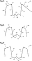
- Figure 3 illustrates the support structure shown in combination with the stent graft of Figure 1 .
- the support structure 60 includes a lateral base 62 and an attaching member 64.
- the lateral base 62 includes distal ends 68, a plurality of proximal bends 70 and a plurality of distal bends 72 disposed between the distal ends 68.
- the lateral base 62 comprises a zig-zag configuration.
- the attaching member 64 includes a pair of opposing struts 66, which extend from the distal ends 68 of the lateral base 62.
- the free ends of the opposing struts 66 are formed as a loop 74 to prevent the sharp edges of the opposing struts 66 from damaging the lumen wall.
- the support structure 60 may be attached to the stent structure 12 or to the tubular graft material 14, or both.
- the lateral base 62 is disposed along the lateral edge 50 of the scallop 48, and as illustrated in Figure 1 , lateral base 62 is disposed distal to the lateral edge 50. No portion of the lateral base 62 protrudes into the opening formed by scallop 48, such that insertion of an extension leg (not shown), if needed, is not blocked and the blood flow through scallop 48 is not obstructed.
- the plurality of proximal bends 70 are closer to the lateral edge 50 of the scallop 48 than the distal bends 72.
- the opposing struts 66 of the support structure 60 are disposed generally along the opposing longitudinal edges 52 of the scallop 48.
- a portion of the support structure 60 may have a shape that generally conforms to the shape of at least a portion of the first or second curved struts 32 and 34 of stent structure 12.
- the opposing struts 66 may have a first segment 76 that generally conforms to the contour of a distal portion of the adjacent first and second curved struts 32 and 34 and a second segment 80 that generally conforms to the contour of the proximal edge 42 of the stent graft material 14.
- a loop 82 may be formed between the first segment 76 and the second segment 80.
- FIG 4 is a perspective view of a stent graft 10 constructed in accordance with a second embodiment of the present disclosure.
- a stent graft 90 has a structure similar to that of the stent graft 10 of Figure 1 , except the support structure 60 has a different shape. Therefore, similar reference numerals are used in Figure 4 for similar components to those in Figure 1 .
- the stent graft 90 includes a stent structure 12, a tubular graft material 14, and a support structure 92. Similar to the first embodiment, scallop 48 is formed in the tubular graft material 14 having a perimeter 54 including a lateral edge 50 and opposing longitudinal edges 52. At least a portion of the opposing longitudinal edges 52 extend along a portion of the first and second curved struts 32 and 34.
- a base strut 56 is disposed along the lateral edge 50 of the scallop 48.
- the perimeter 54 of the scallop 48 is attached at one or more points to the first and second curved struts 32, 34 and the base strut 56.
- the support structure 92 includes a lateral base 94 and an attaching member 96.
- the lateral base 94 includes one or more bent segments 98 and an apex 102 between the one or more bent segments 98 that is adjacent to the base strut 56.
- the attaching member 96 includes a pair of opposing struts104 extending from the lateral base 94 and disposed generally along the longitudinal edges 52 of the scallop 48.
- the opposing struts 104 may be attached at one or more points along a portion of the first and second curved struts 32 and 34 of the proximal stent 22.
- the opposing struts 104 may also include a first segment 76 and a second segment 80 similar to the opposing struts 66 in Figure 3 .
- the support structure 92 may be secured to the stent structure 12 and/or the tubular graft material 14 by any known attachment mechanism.
- the support structure 92 may be attached to the stent structure 12 and/or the tubular graft material 14 by stitching, gluing, welding, or sutures.
- the support structure 92 is sutured along the perimeter 54 of the scallop 48 and just distal to the scallop 48 to connect the support structure 92 and the tubular graft material 14 at sutures 16.
- the support structure 92 may be formed from any biocompatible material such as stainless steel, nickel-titanium alloy (nitinol), ceramic, cobalt/chromium alloys, aluminum or other biocompatible metals and/or composites or alloys such as carbon or carbon fiber.
- the support structure 92 is made of stainless steel and is resilient, which allows the scallop 48 and the stent graft 90 to be delivered in a compressed configuration and to expand in a deployment configu ration.
- FIG. 5 is a view of a support structure 110 for a stent graft in accordance with a third embodiment of the present disclosure.
- a support structure 110 can be used with any suitable stent graft, including stent grafts 10 and 90 shown in Figures 1 and 4 .
- the support structure 110 includes a lateral base 112 and an attaching member 114.
- the lateral base 112 defines one or more bent segments 116, a plurality of proximal bends or apices 118, and a distal bend or apex 120 between the one or more bent segments 116.
- the lateral base 112 defines a zig-zag configuration.
- the attaching member 114 includes a pair of opposing struts 122 attached to the one or more bent segments 116.
- the opposing struts 122 each include a first segment 124 connected to the one or more bent segments 116 of the lateral base 112, and a second segment 126 connected to an end of the first segment 124.
- a loop 82 may be formed between the first segment 124 and the second segment 126.
- One or both of the second segments 126 may further include a third segment 128 connected to the second segment 126.
- the opposing struts may or may not be symmetrical.
- the opposing struts 122 may not be symmetrical in that only one of the opposing struts 122 has a first segment 124, second segment 126, and a third segment 128.
- the other of the opposing struts 122 only has a first segment 124 and a second segment 126.
- the support structure 110 may be attached to the stent structure 12 and/or the graft material 14.
- the first segments 124 may be attached to the graft material 14 along the opposing longitudinal edges 52 of the scallop 48 and/or to at least a portion of the first and second curved struts 32 and 34.
- the second segment 126 may be disposed along at least a portion proximal edge 42 of the tubular graft material 14.
- the third segment 128 may be attached along a portion of the first and second curved struts 32 and 34.
- the three segments 124, 126 and/or 128 shown in Figure 5 may be applied to the other support structures in the disclosure.
- any of the other disclosed support structures may be modified so that the opposing struts 122 have three segments.
- FIG. 6 is a view of a support structure 130 for a stent graft 10 in accordance with a fourth embodiment of the present disclosure.
- a support structure 130 can be used with any suitable stent graft, including stent grafts 10 and 90 shown in Figures 1 and 4 .
- the support structure 130 includes a lateral base 132 and an attaching member 134.
- the lateral base 132 includes one or more bent segments 136, and one or more distal bends or apices 138 and at least one proximal apex 140.
- the attaching member 134 includes a pair of opposing struts 142 extending from the one or more bent segments 136 of the lateral base 132.
- FIG. 7 is a view of a support structure 160 for a stent graft in accordance with a fifth embodiment of the present disclosure.
- a support structure 160 can be used with any suitable stent graft, including stent grafts 10 and 90 shown in Figures 1 and 4 .
- the support structure 160 includes a lateral base 162 and an attaching member 164.
- the lateral base 162 includes one or more bent segments 166, a proximal bend or apex 168 and two distal bends or apices 170.
- the distal apices 170 may each define an obtuse angle.
- the attaching member 164 includes a pair of opposing struts 172 extending from the lateral base 162.
- Figure 8 is a schematic view of a setting fixture for manufacturing a support structure in accordance with the teachings of the present disclosure.
- the setting fixture 180 shown in Figure 8 may be used for manufacturing the support structures 60, 92, 110, 130, and 160 used to enforce the scallop 48 of a stent graft.
- the setting fixture 180 may include a plate body 182 and a plurality of first apertures 184, a plurality of second apertures 186, and a plurality of third apertures 188 through the plate body 182.
- the first apertures 184 are located near the center of the plate body 182.
- the first apertures 184 may be in any arrangement, including in a row or plurality of rows.
- the second apertures 186 are located near an edge or corner of the plate 182 and the third apertures 188 are located at an adjacent edge or corner of the plate 182.
- the plurality of first apertures 184, second apertures 186 and third apertures 188 may have any number of openings in the plate body 182.
- the plurality of first apertures 184 may have 15 openings
- the plurality of second apertures 186 may have 3 openings
- the plurality of third apertures 188 may have 3 openings in the plate body 182.
- the first apertures 184 may be used to set the shape of the lateral base of the support structure, whereas the second apertures 186 and the third apertures 188 may be used to set the two opposing struts of the attaching member of the support structure.
- the support structure may be formed by securing one or more wires to the plate body 182 at locations corresponding to one or more of the first, second and third apertures 184, 186, 188 to set the shape of the support structure.
- a single wire is used to create the support structure.
- the shape of the lateral base of the support structure may be set by the first apertures 184 by securing a portion of the wire to the first apertures 184 at predetermined locations.
- the lateral base may be set to have any shape, including a linear shape, a zig-zag shape, a single curve shape, an arc shape, a triangular shape, or a wavy shape.
- the lateral base can have any other shape as long as it is disposed distally of the bottom edge of the scallop 48 to provide additional support for the scallop 48.
- the shape of the opposing struts of the attaching member of the support structure may be set by the second and third apertures 186 and 188 by securing another portion of the wire to the second apertures 186 and the third apertures 188, respectively, at predetermined locations.
- the wire may be subject to heat treatment to set the configuration of the support structure.
- the support structure may be attached to any existing stent graft to provide additional support for a scallop 48.
Landscapes
- Health & Medical Sciences (AREA)
- Gastroenterology & Hepatology (AREA)
- Pulmonology (AREA)
- Cardiology (AREA)
- Oral & Maxillofacial Surgery (AREA)
- Transplantation (AREA)
- Engineering & Computer Science (AREA)
- Biomedical Technology (AREA)
- Heart & Thoracic Surgery (AREA)
- Vascular Medicine (AREA)
- Life Sciences & Earth Sciences (AREA)
- Animal Behavior & Ethology (AREA)
- General Health & Medical Sciences (AREA)
- Public Health (AREA)
- Veterinary Medicine (AREA)
- Prostheses (AREA)
Abstract
Description
- The present disclosure relates to a prosthesis such as a stent graft for deployment in a body vessel, including at arterial branching points.
- A stent graft is commonly used to reinforce a weakened area in an artery such as an aneurysm. Blood pressure, among other factors, can cause this weakened area to bulge over time. The bulged area can eventually enlarge and rupture if not treated. The stent graft is designed to seal tightly with the artery above and below the aneurysm to allow the blood to flow through the stent graft without causing the weakened area to bulge. When the aneurysm is located in a region of a body lumen adjacent to a branch vessel, the stent graft may need to accommodate the opening to that vessel so that blood flow is not blocked or obstructed. For example, a stent graft may include fenestrations, branches, bare stents and the like to allow blood to flow into a branch vessel.
- The present invention seeks to provide an improved prosthesis such as a stent graft.
- According to an aspect of the present invention, there is provided a stent graft comprising: a substantially tubular graft having a first end and a second end; a scallop cut out of one or both of the first end and the second end, wherein the scallop extends away from an end edge of the substantially tubular graft and has a perimeter defined by graft material, wherein the perimeter has at least three sides including a lateral side having a lateral edge substantially parallel to the end edge and two longitudinal sides extending between the lateral side and the end edge; and a scallop support structure at least partially bounded about the perimeter of the scallop, the scallop support structure comprising at least two substantially longitudinal perimeter support sections, and an undulating lateral base extending between the at least two substantially longitudinal perimeter support sections, wherein the undulating lateral base has at least two undulations; wherein one of the at least two perimeter support sections is attached along and defines one of the two longitudinal sides and another of the at least two perimeter support sections is attached along and defines the other of the longitudinal sides; and wherein the undulating lateral base is disposed along the lateral base of the scallop and , preferably entirely, overlaps the graft material.
- Another aspect of the present invention provides a stent-graft having at least one scallop or cut out in an edge of the graft. The scallop has three sides including a lateral side having a lateral edge. A scallop support structure at least partially conforms to the perimeter of the scallop and has an undulating base that extends below the edge of the scallop and has peaks and valleys. The peaks abut the edge of the scallop and the valleys extend below the edge of the scallop. The scallop support structure has at least two substantially longitudinal perimeter support sections, and the undulating lateral base extends between the at least two substantially longitudinal perimeter support sections. The undulating lateral base has at least two undulations. The two perimeter support sections bound the longitudinal sides.
- Further aspects of the invention are described here with reference to the drawings.
- Embodiments of the present invention are described below, by way of example only, with reference to the accompanying drawings, in which:
-
FIGURE 1 is a perspective view of a stent graft having a scallop-shaped opening at one end; -
FIGURE 2 is a front view of the tubular graft material shown inFigure 1 ; -
FIGURE 3 is a support structure for a scallop-shaped opening shown inFigure 1 ; -
FIGURE 4 is a perspective view of a stent graft with another example of a support structure for a scallop-shaped opening in a stent graft; -
FIGURE 5 is another example of a support structure for a scallop-shaped opening in a stent graft; -
FIGURE 6 is a view of another example of a support structure for a scallop-shaped opening in a stent graft; -
FIGURE 7 is a view of another example of a support structure for a scallop-shaped opening in a stent graft; -
FIGURE 8 is an example of a setting fixture for manufacturing a support structure; - The drawings described herein are for illustration purposes only and are not intended to limit the scope of the present disclosure in any way.
- In the present application, the term "proximal" refers to a direction that is farthest away from the operator when referring to a delivery device, while the term "distal" refers to a direction that is generally closest to the operator using the delivery device. The distal end of the delivery device is that portion of the device that is intended to remain outside of a patient during a procedure. When referring to the prosthesis itself relative to the delivery device, the proximal end of the prosthesis is that part of the prosthesis nearest the proximal end of the delivery device and the distal end of the prosthesis is that end that is closest to the distal end of the delivery device.
-
Figure 1 illustrates a portion of a stent graft configured in accordance with a first embodiment of the present disclosure. As shown there, astent graft 10 includes astent structure 12, and atubular graft material 14 attached to thestent structure 12. Asuitable stent structure 12 for use in connection with thestent graft 10 described herein may include one or more self-expanding or mechanically-expandable stents or both, and may be deployed according to conventional methodology. A self-expanding stent may be manufactured from stainless steel or a shape-memory alloy, such as nickel titanium alloy (nitinol), cobalt chromium alloy or any other suitable material including cobalt-chromium alloys, amorphous metals, and/or non-metallic materials as would be recognized by one of skill in the art. If the stent comprises a self-expanding material such as nitinol, the stent may be heat-set into the desired expanded state whereby the stent can assume a relaxed radially expanded configuration. Additionally or alternatively, thestent graft 10 may be mechanically expanded, such as through the use of an expandable balloon placed within a lumen of thestent graft 10 and then radially outwardly expanded to thereby expand thestent graft 10. - In one example, the
stent structure 12 may include a self-expandableproximal sealing stent 22 to engage a vessel wall when deployed adjacent to a weakened area of the body lumen, or aneurysm. Thestent structure 12 may also include one or a series ofstents 24 such as z-stents or the like located distal to theproximal sealing stent 22 as shown inFigure 1 . Thestent structure 12 may be attached to the interior surface of thegraft material 14 or it may be exposed on the exterior of the graft material, or both. The stents may all be the same or they may be different. Thestent graft 10 may have any desirable design or configuration depending on the particular use, position of placement in a vessel and/or the procedure being performed. In one example, thestent graft 10 resembles the stent grafts disclosed inU.S. Patent Nos. 7,413,573 ,8,672,993 , and8,702,780 , all of which are incorporated by reference in their entirety herein. - As will be apparent from
Figure 1 , thestent 12 preferably extends around the entire circumference of the graft and across the opening of thescallop 48, described in further detail below. - Stents at one or both ends of the graft material may be located on the internal surface of at least a portion of the stent graft to provide a smooth outside sealing surface of the graft material against the vessel wall adjacent to the aneurysm as shown in
Figure 1 . Thetubular graft material 14 may be attached to thestent structure 12 throughsutures 16 or any other known attachment mechanisms. - The
stent graft 10 includes aproximal end 18 and adistal end 20. As shown inFigure 2 , thetubular graft material 14 defines an elongated tubular body extending between theproximal end 18 and thedistal end 20. As will be described in greater detail below, thetubular graft material 14 may have one or more scallop-shaped openings or fenestrations 48 (a "scallop") that are cut out of the material of thestent graft 10. It is also contemplated that thestent graft 10 may be bifurcated at one end to accommodate branch vessels such as the iliac arteries. -
Figure 2 is a front view of thetubular graft material 14 shown inFigure 1 . Thetubular graft material 14 may be made of a biocompatible graft material such as polyethylene terephthalate (PET sold under the tradename Dacron®), polyurethane urea optionally blended with a siloxane containing surface modifying additive (such as that sold under the tradename Thoralon®), polytetrafluoroethylene (PTFE) or other synthetic bio-compatible material. A naturally occurring biomaterial, such as collagen, is highly desirable, particularly a specially derived collagen material known as an extracellular matrix (ECM) material, such as small intestinal submucosa (SIS) commercially available from Cook Biotech, West Lafayette, Ind. Besides SIS, examples of ECM's include pericardium, stomach submucosa, liver basement membrane, urinary bladder submucosa, tissue mucosa, and dura mater. - Referring to
Figure 2 , thetubular graft material 14 includes aproximal edge 42, adistal edge 44, and atubular body 46 extending therebetween. Thetubular graft material 14 may further define ascallop 48 at one or both ends. In one example, thescallop 48 is formed near theproximal end 18 of thestent graft 10 and thescallop 48 opens to theproximal end 18 of thestent graft 10. In another example (not shown), ascallop 48 is located near thedistal edge 44 of the stent graft and opens to thedistal end 20 of thestent graft 10 and is otherwise similar to thescallop 48 located near theproximal end 18 of thestent graft 10. In one example, thescallop 48 is positioned to allow blood flow into a branch vessel near the site in which thestent graft 10 is placed in the vasculature. - In one example,
scallop 48 may be adjacent to theproximal edge 42. As shown inFigures 1-2 , thescallop 48 is a cutout portion extending below and distally from theproximal edge 42 of thetubular graft material 14. Thescallop 48 is defined by alateral edge 50 and two opposing longitudinal edges 52. Thelateral edge 50 is substantially parallel to theproximal edge 42 of thetubular graft material 14. The opposinglongitudinal edges 52 extend generally in a longitudinal direction along the length of thetubular graft material 14 between theproximal edge 42 of thetubular graft material 14 andlateral edge 50 of thescallop 48. Thelateral edge 50 and the two opposinglongitudinal edges 52 form aperimeter 54 of thescallop 48, which, in one example, defines a generally U-shape configuration. This configuration may expose some of thecells 38 of the proximal stent 22 (as shown inFigure 1 ). - In some embodiments, the
edges edge 50 may be substantially transverse (that is extending perpendicularly) to the longitudinal axis of thegraft tubing 14. The skilled person will appreciate that the edges may have other shapes as shown in the drawings. - Referring back to
Figure 1 , thestent structure 12 may include a proximal sealingstent 22 and one or moredistal stents 24. Theproximal stent 22 and the one or moredistal stents 24 may have the same or different structures. In the embodiment illustrated inFigure 1 , thedistal stent 24 includes a plurality of firststraight struts 26 and a plurality of secondstraight struts 28 alternately arranged to form a zig-zag ring. The plurality of first and secondstraight struts apices 30. Thetubular graft material 14 may be attached to thedistal stent 24 by one or more sutures. In one example, sutures 16 connect thegraft material 14 and thedistal stent 24 at theapices 30. - The
proximal stent 22 may include a plurality of firstcurved struts 32 and a plurality of secondcurved struts 34. The first and secondcurved struts curved struts apices 36 so that one firstcurved strut 32 and one adjacent secondcurved strut 34 form aclosed cell 38 having an enlarged middle portion and opposing narrowed portions. Theclosed cells 38 are connected to at least one point along thesides 40 of the first and secondcurved struts apices 36 of the first and secondcurved struts - Referring back to
Figure 1 , the opposinglongitudinal edges 52 of thescallop 48 may be aligned with a portion of the adjacent first and secondcurved struts proximal stent 22. In the example shown inFigure 1 , thelongitudinal edge 52 on the right side of thescallop 48 overlaps a distal portion of the firstcurved strut 32, whereas thelongitudinal edge 52 on the left side of thescallop 48 overlaps a distal portion of the secondcurved strut 34. - The opposing
longitudinal edges 52 of thescallop 48 of thetubular graft material 14 can be stitched bysutures 16 to the first and secondcurved struts curved struts longitudinal edges 52 can conform to a part of the shape of the first and secondcurved struts - As described in more detail below, the
scallop 48 formed in thetubular graft material 14 may be supported by one or more structures, including abase strut 56 and asupport structure 60 that provides additional support forscallop 48. Abase strut 56 may be disposed along thelateral edge 50 of thescallop 48. Thebase strut 56 may be secured to thestent structure 12 and/or thetubular graft material 14 by any known attachment mechanisms. For example, thebase strut 56 may be attached to thestent structure 12 and/or thetubular graft material 14 by stitching, gluing, welding, or sutures. In one example, thebase strut 56 is sewn along thelateral edge 50 of thescallop 48 to connect thesupport structure 60 and thetubular graft material 14 atstitch line 15. - The
stent graft 10 may further include asupport structure 60 to provide additional support for thescallop 48 of thetubular graft material 14. The support structure may be located anywhere on thestent graft 10, and in one example, the support structure is located adjacent to the perimeter of thescallop 48. - The
support structure 60 may have any suitable design that preferably corresponds to and/or accommodates the general shape and dimension of thescallop 48. As described below,Figures 1 and3-7 show several embodiments of support structures that can be used to supportscallop 48. In one example, thesupport structure 60 shown inFigure 1 (and described in greater detail below in connection withFigure 3 ) may have a series of zig-zag-shaped segments located distal to thelateral edge 50 of thescallop 48. - The
support structure 60 may be secured to thestent structure 12 and/or thetubular graft material 14 by any known attachment mechanisms. For example, thesupport structure 60 may be attached to thestent structure 12 and/or to thetubular graft material 14 by stitching, gluing, welding, or sutures. In one example, thesupport structure 60 is sewn onto thegraft material 14 along one or more points of thelongitudinal edges 52 ofscallop 48. Thesupport structure 60 may also be sewn onto thegraft material 14 just distal to thelateral edge 50 of thescallop 48. - The support structures described herein may be formed from any biocompatible material such as stainless steel, nickel-titanium alloy (nitinol), ceramic, cobalt/chromium alloys, aluminum or other biocompatible metals and/or composites or alloys such as carbon or carbon fiber. In one example, the support structures are made of stainless steel and are resilient, which allows the
stent graft 10 to be delivered to a target site in a compressed configuration and to expand in a deployment configuration. - The support structure 60 (and other support structures disclosed below) may be configured to support the
graft material 14. The support structure may also serve to reduce tearing or separation of thegraft material 14 from thestent structure 12. In one example, thesupport structure 60 reinforces thescallop 48 so that blood flow forces do not tear, separate, or disfigure the graft material and/or push thegraft material 14 away from or off of thestent structure 12. - In the case of balloon expandable stents, the support structure 60 (and other support structures disclosed below) may provide a more dimensionally
stable scallop 48 in thetubular graft material 14, particularly when a balloon expandable stent is used as a leg or side arm extension through a branch vessel (not shown). With thesupport structure 60, the force of the balloon expansion is less likely to tear thegraft material 14 from thestent structure 12. -
Figure 3 illustrates the support structure shown in combination with the stent graft ofFigure 1 . Referring toFigure 3 , thesupport structure 60 includes alateral base 62 and an attachingmember 64. Thelateral base 62 includes distal ends 68, a plurality ofproximal bends 70 and a plurality ofdistal bends 72 disposed between the distal ends 68. Thelateral base 62 comprises a zig-zag configuration. The attachingmember 64 includes a pair of opposingstruts 66, which extend from the distal ends 68 of thelateral base 62. The free ends of the opposing struts 66 are formed as aloop 74 to prevent the sharp edges of the opposing struts 66 from damaging the lumen wall. - The
support structure 60 may be attached to thestent structure 12 or to thetubular graft material 14, or both. In one example, thelateral base 62 is disposed along thelateral edge 50 of thescallop 48, and as illustrated inFigure 1 ,lateral base 62 is disposed distal to thelateral edge 50. No portion of thelateral base 62 protrudes into the opening formed byscallop 48, such that insertion of an extension leg (not shown), if needed, is not blocked and the blood flow throughscallop 48 is not obstructed. The plurality ofproximal bends 70 are closer to thelateral edge 50 of thescallop 48 than the distal bends 72. The opposing struts 66 of thesupport structure 60 are disposed generally along the opposinglongitudinal edges 52 of thescallop 48. - A portion of the
support structure 60 may have a shape that generally conforms to the shape of at least a portion of the first or secondcurved struts stent structure 12. As an example shown inFigure 3 , the opposing struts 66 may have afirst segment 76 that generally conforms to the contour of a distal portion of the adjacent first and secondcurved struts second segment 80 that generally conforms to the contour of theproximal edge 42 of thestent graft material 14. Aloop 82 may be formed between thefirst segment 76 and thesecond segment 80. -
Figure 4 is a perspective view of astent graft 10 constructed in accordance with a second embodiment of the present disclosure. Referring toFigure 4 , astent graft 90 has a structure similar to that of thestent graft 10 ofFigure 1 , except thesupport structure 60 has a different shape. Therefore, similar reference numerals are used inFigure 4 for similar components to those inFigure 1 . - The
stent graft 90 includes astent structure 12, atubular graft material 14, and asupport structure 92. Similar to the first embodiment,scallop 48 is formed in thetubular graft material 14 having aperimeter 54 including alateral edge 50 and opposing longitudinal edges 52. At least a portion of the opposinglongitudinal edges 52 extend along a portion of the first and secondcurved struts - A
base strut 56 is disposed along thelateral edge 50 of thescallop 48. Theperimeter 54 of thescallop 48 is attached at one or more points to the first and secondcurved struts base strut 56. - The
support structure 92 includes alateral base 94 and an attachingmember 96. Thelateral base 94 includes one or morebent segments 98 and an apex 102 between the one or morebent segments 98 that is adjacent to thebase strut 56. The attachingmember 96 includes a pair of opposing struts104 extending from thelateral base 94 and disposed generally along thelongitudinal edges 52 of thescallop 48. The opposing struts 104 may be attached at one or more points along a portion of the first and secondcurved struts proximal stent 22. In one example, the opposingstruts 104 may also include afirst segment 76 and asecond segment 80 similar to the opposing struts 66 inFigure 3 . - Similar to support
structure 60, thesupport structure 92 may be secured to thestent structure 12 and/or thetubular graft material 14 by any known attachment mechanism. For example, thesupport structure 92 may be attached to thestent structure 12 and/or thetubular graft material 14 by stitching, gluing, welding, or sutures. In one example shown inFigure 4 , thesupport structure 92 is sutured along theperimeter 54 of thescallop 48 and just distal to thescallop 48 to connect thesupport structure 92 and thetubular graft material 14 atsutures 16. - The
support structure 92 may be formed from any biocompatible material such as stainless steel, nickel-titanium alloy (nitinol), ceramic, cobalt/chromium alloys, aluminum or other biocompatible metals and/or composites or alloys such as carbon or carbon fiber. In one example, thesupport structure 92 is made of stainless steel and is resilient, which allows thescallop 48 and thestent graft 90 to be delivered in a compressed configuration and to expand in a deployment configu ration. -
Figure 5 is a view of asupport structure 110 for a stent graft in accordance with a third embodiment of the present disclosure. Referring toFigure 5 , asupport structure 110 can be used with any suitable stent graft, includingstent grafts Figures 1 and4 . Thesupport structure 110 includes alateral base 112 and an attachingmember 114. Thelateral base 112 defines one or morebent segments 116, a plurality of proximal bends orapices 118, and a distal bend or apex 120 between the one or morebent segments 116. In one example, thelateral base 112 defines a zig-zag configuration. The attachingmember 114 includes a pair of opposingstruts 122 attached to the one or morebent segments 116. - The opposing struts 122 each include a
first segment 124 connected to the one or morebent segments 116 of thelateral base 112, and asecond segment 126 connected to an end of thefirst segment 124. Aloop 82 may be formed between thefirst segment 124 and thesecond segment 126. One or both of thesecond segments 126 may further include athird segment 128 connected to thesecond segment 126. The opposing struts may or may not be symmetrical. For example, as shown inFigure 5 , the opposingstruts 122 may not be symmetrical in that only one of the opposingstruts 122 has afirst segment 124,second segment 126, and athird segment 128. The other of the opposingstruts 122 only has afirst segment 124 and asecond segment 126. - The
support structure 110 may be attached to thestent structure 12 and/or thegraft material 14. In one example, thefirst segments 124 may be attached to thegraft material 14 along the opposinglongitudinal edges 52 of thescallop 48 and/or to at least a portion of the first and secondcurved struts second segment 126 may be disposed along at least a portionproximal edge 42 of thetubular graft material 14. Thethird segment 128 may be attached along a portion of the first and secondcurved struts - The three
segments Figure 5 may be applied to the other support structures in the disclosure. In other words, any of the other disclosed support structures may be modified so that the opposingstruts 122 have three segments. -
Figure 6 is a view of asupport structure 130 for astent graft 10 in accordance with a fourth embodiment of the present disclosure. Referring toFigure 6 , asupport structure 130 can be used with any suitable stent graft, includingstent grafts Figures 1 and4 . Thesupport structure 130 includes a lateral base 132 and an attachingmember 134. The lateral base 132 includes one or morebent segments 136, and one or more distal bends orapices 138 and at least oneproximal apex 140. The attachingmember 134 includes a pair of opposingstruts 142 extending from the one or morebent segments 136 of the lateral base 132. The opposing struts 142 each include afirst segment 144, asecond segment 146, and athird segment 148.Figure 7 is a view of asupport structure 160 for a stent graft in accordance with a fifth embodiment of the present disclosure. Referring toFigure 7 , asupport structure 160 can be used with any suitable stent graft, includingstent grafts Figures 1 and4 . Thesupport structure 160 includes alateral base 162 and an attachingmember 164. Thelateral base 162 includes one or morebent segments 166, a proximal bend orapex 168 and two distal bends orapices 170. Thedistal apices 170 may each define an obtuse angle. - The attaching
member 164 includes a pair of opposingstruts 172 extending from thelateral base 162.Figure 8 is a schematic view of a setting fixture for manufacturing a support structure in accordance with the teachings of the present disclosure. - The
setting fixture 180 shown inFigure 8 may be used for manufacturing thesupport structures scallop 48 of a stent graft. Thesetting fixture 180 may include aplate body 182 and a plurality offirst apertures 184, a plurality ofsecond apertures 186, and a plurality ofthird apertures 188 through theplate body 182. In one example, thefirst apertures 184 are located near the center of theplate body 182. Thefirst apertures 184 may be in any arrangement, including in a row or plurality of rows. In one example, thesecond apertures 186 are located near an edge or corner of theplate 182 and thethird apertures 188 are located at an adjacent edge or corner of theplate 182. - The plurality of
first apertures 184,second apertures 186 andthird apertures 188 may have any number of openings in theplate body 182. In one example, the plurality offirst apertures 184 may have 15 openings, the plurality ofsecond apertures 186 may have 3 openings and the plurality ofthird apertures 188 may have 3 openings in theplate body 182. - The
first apertures 184 may be used to set the shape of the lateral base of the support structure, whereas thesecond apertures 186 and thethird apertures 188 may be used to set the two opposing struts of the attaching member of the support structure. - The support structure according to any of the embodiments in this disclosure may be formed by securing one or more wires to the
plate body 182 at locations corresponding to one or more of the first, second andthird apertures first apertures 184 by securing a portion of the wire to thefirst apertures 184 at predetermined locations. The lateral base may be set to have any shape, including a linear shape, a zig-zag shape, a single curve shape, an arc shape, a triangular shape, or a wavy shape. The lateral base can have any other shape as long as it is disposed distally of the bottom edge of thescallop 48 to provide additional support for thescallop 48. The shape of the opposing struts of the attaching member of the support structure may be set by the second andthird apertures second apertures 186 and thethird apertures 188, respectively, at predetermined locations. - After the wire is attached to the
setting fixture 180, the wire may be subject to heat treatment to set the configuration of the support structure. After the support structure is formed, the support structure may be attached to any existing stent graft to provide additional support for ascallop 48. - It should be noted that the disclosure is not limited to the embodiment described and illustrated as examples.
- The disclosures in United States patent application serial no.
62/487,108
Claims (16)
- A stent graft comprising:a substantially tubular graft having a first end and a second end;a scallop cut out of one or both of the first end and the second end, wherein the scallop extends away from an end edge of the substantially tubular graft and has a perimeter defined by graft material, wherein the perimeter has at least three sides including a lateral side having a lateral edge substantially parallel to the end edge and two longitudinal sides extending between the lateral side and the end edge; anda scallop support structure at least partially bounded about the perimeter of the scallop, the scallop support structure comprising at least two substantially longitudinal perimeter support sections, and an undulating lateral base extending between the at least two substantially longitudinal perimeter support sections, wherein the undulating lateral base has at least two undulations;wherein one of the at least two perimeter support sections is attached along and defines one of the two longitudinal sides and another of the at least two perimeter support sections is attached along and defines the other of the longitudinal sides; andwherein the undulating lateral base is disposed along the lateral base of the scallop and overlaps the graft material.
- A stent graft according to claim 1, wherein the undulations of the undulating lateral side comprise a plurality of peaks and a plurality of valleys and the plurality of peaks abut the lateral edge of the lateral side and the plurality of valleys extend distally away from the lateral edge of the scallop.
- A stent graft according to claim 1 or 2, wherein the undulations of the undulating lateral base comprise at least one peak abutting the lateral base and at least two valleys extending away from the lateral edge of the scallop.
- A stent graft according to any preceding claim, wherein the scallop support structure is formed of a single continuous wire.
- A stent graft according to any preceding claim, wherein the undulations of the undulating lateral base comprise:a series of U-shaped undulations, and preferably wherein end edges of the U-shaped undulations abut the edge of the lateral side; ora series of V-shaped undulations, and preferably wherein end edges of the V-shaped undulations abut the edge of the lateral side.
- A stent graft according to any preceding claim, comprising a support wire, separate from the undulating lateral base, wherein the support wire bounds at least the length of the edge of the lateral side and is coincident with the edge of the lateral side.
- A stent graft according to any preceding claim, wherein the first end of the graft is the proximal end of the graft and the second end of the graft is the distal end of the graft.
- A stent graft comprising:a substantially tubular graft of graft material having a proximal end, a distal end, a proximal end edge, and a distal end edge;a scallop cut out of the graft material at the proximal end and having a three sided perimeter including a lateral side having a lateral edge substantially parallel to the proximal end edge and two longitudinal sides extending from the lateral base to the proximal end edge, wherein the scallop extends away from the proximal end edge and toward the distal end; anda scallop support structure at least partially bounding the perimeter of the scallop, the scallop support structure comprising two substantially longitudinal perimeter support sections, and an undulating lateral base extending between the two substantially longitudinal perimeter support sections, wherein the undulating lateral base comprises a plurality of undulations extending from one of the two substantially longitudinal perimeter support sections to another of the two substantially longitudinal perimeter support sections;wherein one of the two substantially longitudinal perimeter sections is attached along and bounds one of the two longitudinal sides of the scallop and another of the two substantially longitudinal perimeter sections is attached along bounds the other of the longitudinal sides of the scallop; andwherein the undulating lateral base of the scallop support structure extends distally of the lateral edge of the scallop and overlaps the graft material, wherein the undulating lateral base supports the length of the lateral base of the scallop.
- A stent graft according to claim 8, wherein the undulations of the undulating lateral base comprise a plurality of peaks and a plurality of valleys and the plurality of peaks abut the lateral edge of the lateral side of the scallop and the plurality of valleys extend distally away from the lateral edge of the scallop.
- A stent graft according to claim 8 or 9, wherein the undulations of the undulating lateral base comprise at least one peak abutting the lateral edge of the scallop and at least two valleys extending away from the lateral edge of the scallop.
- A stent graft according to any one of claims 8 to 10, wherein the scallop support structure is formed of a single continuous wire.
- A stent graft according to any one of claims 8 to 11, wherein the undulations of the undulating lateral side base comprise:a series of U-shaped undulations, preferably wherein end edges of the U-shaped undulations abut the edge of the lateral side of the scallop; ora series of V-shaped undulations, preferably wherein end edges of the V-shaped undulations abut the edge of the lateral side of the scallop.
- A stent graft according to any one of claims 8 to 12, comprising a support wire, separate from the undulating lateral base, wherein the support wire bounds the length of the edge of the lateral side of the scallop.
- A stent graft comprising:a substantially tubular graft having a first end and a second end and a plurality of stents along a length of the tubular graft from the first end to the second end;a scallop cut out of one or both of the first end and the second end, wherein the scallop extends away from an end edge of the substantially tubular graft and has a perimeter defined by graft material, wherein the perimeter has at least three sides including a lateral side having a lateral edge substantially parallel to the end edge and two longitudinal sides extending between the lateral side and the end edge; anda scallop support structure at least partially bounded about the perimeter of the scallop, the scallop support structure comprising at least two substantially longitudinal perimeter support sections, and an undulating lateral base extending between the at least two substantially longitudinal perimeter support sections, wherein the undulating lateral base has at least two undulations;wherein one of the at least two perimeter support sections is attached along bounds one of the two longitudinal sides and another of the at least two perimeter support sections is attached along and bounds the other of the longitudinal sides;wherein the undulating lateral base is disposed along the lateral base of the scallop and entirely overlaps the graft material, andwherein the scallop support structure is a separate structural element from any of the plurality of stents.
- A stent graft according to any preceding claim, comprising a plurality of stents along a length of the tubular graft from the first end to the second end, wherein the scallop support structure is a separate structural element from any of the plurality of stents.
- A stent graft according to any preceding claim, wherein the scallop support structure comprises a second lateral base that extends along the lateral end to define the lateral edge.
Applications Claiming Priority (1)
| Application Number | Priority Date | Filing Date | Title |
|---|---|---|---|
| US201762487108P | 2017-04-19 | 2017-04-19 |
Publications (2)
| Publication Number | Publication Date |
|---|---|
| EP3391853A1 true EP3391853A1 (en) | 2018-10-24 |
| EP3391853B1 EP3391853B1 (en) | 2019-11-20 |
Family
ID=62044631
Family Applications (1)
| Application Number | Title | Priority Date | Filing Date |
|---|---|---|---|
| EP18275052.1A Active EP3391853B1 (en) | 2017-04-19 | 2018-04-19 | Support structure for scalloped grafts |
Country Status (1)
| Country | Link |
|---|---|
| EP (1) | EP3391853B1 (en) |
Citations (5)
| Publication number | Priority date | Publication date | Assignee | Title |
|---|---|---|---|---|
| US7413573B2 (en) | 2003-10-10 | 2008-08-19 | William A. Cook Australia Pty. Ltd. | Fenestrated stent grafts |
| US20130116775A1 (en) * | 2010-08-21 | 2013-05-09 | William A. Cook Australia Pty. Ltd. | Prosthesis having pivoting fenestration |
| US20130289701A1 (en) * | 2012-04-27 | 2013-10-31 | Medtronic Vascular, Inc. | Stent-graft prosthesis for placement in the abdominal aorta |
| US8672993B2 (en) | 2009-03-26 | 2014-03-18 | Cook Medical Technologies Llc | Pararenal stent graft |
| US8702780B2 (en) | 2007-03-06 | 2014-04-22 | Cook Medical Technologies Llc | Endovascular deployment device |
-
2018
- 2018-04-19 EP EP18275052.1A patent/EP3391853B1/en active Active
Patent Citations (5)
| Publication number | Priority date | Publication date | Assignee | Title |
|---|---|---|---|---|
| US7413573B2 (en) | 2003-10-10 | 2008-08-19 | William A. Cook Australia Pty. Ltd. | Fenestrated stent grafts |
| US8702780B2 (en) | 2007-03-06 | 2014-04-22 | Cook Medical Technologies Llc | Endovascular deployment device |
| US8672993B2 (en) | 2009-03-26 | 2014-03-18 | Cook Medical Technologies Llc | Pararenal stent graft |
| US20130116775A1 (en) * | 2010-08-21 | 2013-05-09 | William A. Cook Australia Pty. Ltd. | Prosthesis having pivoting fenestration |
| US20130289701A1 (en) * | 2012-04-27 | 2013-10-31 | Medtronic Vascular, Inc. | Stent-graft prosthesis for placement in the abdominal aorta |
Also Published As
| Publication number | Publication date |
|---|---|
| EP3391853B1 (en) | 2019-11-20 |
Similar Documents
| Publication | Publication Date | Title |
|---|---|---|
| EP2574306B1 (en) | Endoluminal prosthesis with steerable branch | |
| US10376395B2 (en) | Fenestrated stent grafts | |
| JP4726382B2 (en) | Stent graft | |
| US9848977B2 (en) | Aortic graft device | |
| EP2606853B1 (en) | Hybrid aortic arch replacement | |
| US9788933B2 (en) | Medical device delivery system and deployment method | |
| EP3191018B1 (en) | Frame structures, stent grafts incorporating the same | |
| EP3040050A1 (en) | Support structures for prostheses with branching portions | |
| EP3449871A2 (en) | Endoluminal prosthesis with an aortic sinus stent assembly | |
| US10959826B2 (en) | Support structure for scalloped grafts | |
| EP3431038B1 (en) | Non-cylindrical variable pitch mesh top stent | |
| EP3391853B1 (en) | Support structure for scalloped grafts | |
| EP3431039B1 (en) | Non-cylindrical mesh top stent with twisted sections |
Legal Events
| Date | Code | Title | Description |
|---|---|---|---|
| PUAI | Public reference made under article 153(3) epc to a published international application that has entered the european phase |
Free format text: ORIGINAL CODE: 0009012 |
|
| STAA | Information on the status of an ep patent application or granted ep patent |
Free format text: STATUS: THE APPLICATION HAS BEEN PUBLISHED |
|
| AK | Designated contracting states |
Kind code of ref document: A1 Designated state(s): AL AT BE BG CH CY CZ DE DK EE ES FI FR GB GR HR HU IE IS IT LI LT LU LV MC MK MT NL NO PL PT RO RS SE SI SK SM TR |
|
| AX | Request for extension of the european patent |
Extension state: BA ME |
|
| STAA | Information on the status of an ep patent application or granted ep patent |
Free format text: STATUS: REQUEST FOR EXAMINATION WAS MADE |
|
| 17P | Request for examination filed |
Effective date: 20190326 |
|
| RBV | Designated contracting states (corrected) |
Designated state(s): AL AT BE BG CH CY CZ DE DK EE ES FI FR GB GR HR HU IE IS IT LI LT LU LV MC MK MT NL NO PL PT RO RS SE SI SK SM TR |
|
| GRAJ | Information related to disapproval of communication of intention to grant by the applicant or resumption of examination proceedings by the epo deleted |
Free format text: ORIGINAL CODE: EPIDOSDIGR1 |
|
| STAA | Information on the status of an ep patent application or granted ep patent |
Free format text: STATUS: GRANT OF PATENT IS INTENDED |
|
| GRAP | Despatch of communication of intention to grant a patent |
Free format text: ORIGINAL CODE: EPIDOSNIGR1 |
|
| RIC1 | Information provided on ipc code assigned before grant |
Ipc: A61F 2/07 20130101AFI20190528BHEP |
|
| INTG | Intention to grant announced |
Effective date: 20190702 |
|
| GRAA | (expected) grant |
Free format text: ORIGINAL CODE: 0009210 |
|
| STAA | Information on the status of an ep patent application or granted ep patent |
Free format text: STATUS: THE PATENT HAS BEEN GRANTED |
|
| GRAS | Grant fee paid |
Free format text: ORIGINAL CODE: EPIDOSNIGR3 |
|
| AK | Designated contracting states |
Kind code of ref document: B1 Designated state(s): AL AT BE BG CH CY CZ DE DK EE ES FI FR GB GR HR HU IE IS IT LI LT LU LV MC MK MT NL NO PL PT RO RS SE SI SK SM TR |
|
| REG | Reference to a national code |
Ref country code: GB Ref legal event code: FG4D |
|
| REG | Reference to a national code |
Ref country code: CH Ref legal event code: EP |
|
| REG | Reference to a national code |
Ref country code: IE Ref legal event code: FG4D |
|
| REG | Reference to a national code |
Ref country code: DE Ref legal event code: R096 Ref document number: 602018001288 Country of ref document: DE |
|
| REG | Reference to a national code |
Ref country code: AT Ref legal event code: REF Ref document number: 1203311 Country of ref document: AT Kind code of ref document: T Effective date: 20191215 |
|
| REG | Reference to a national code |
Ref country code: NL Ref legal event code: MP Effective date: 20191120 |
|
| REG | Reference to a national code |
Ref country code: LT Ref legal event code: MG4D |
|
| PG25 | Lapsed in a contracting state [announced via postgrant information from national office to epo] |
Ref country code: BG Free format text: LAPSE BECAUSE OF FAILURE TO SUBMIT A TRANSLATION OF THE DESCRIPTION OR TO PAY THE FEE WITHIN THE PRESCRIBED TIME-LIMIT Effective date: 20200220 Ref country code: NO Free format text: LAPSE BECAUSE OF FAILURE TO SUBMIT A TRANSLATION OF THE DESCRIPTION OR TO PAY THE FEE WITHIN THE PRESCRIBED TIME-LIMIT Effective date: 20200220 Ref country code: FI Free format text: LAPSE BECAUSE OF FAILURE TO SUBMIT A TRANSLATION OF THE DESCRIPTION OR TO PAY THE FEE WITHIN THE PRESCRIBED TIME-LIMIT Effective date: 20191120 Ref country code: GR Free format text: LAPSE BECAUSE OF FAILURE TO SUBMIT A TRANSLATION OF THE DESCRIPTION OR TO PAY THE FEE WITHIN THE PRESCRIBED TIME-LIMIT Effective date: 20200221 Ref country code: NL Free format text: LAPSE BECAUSE OF FAILURE TO SUBMIT A TRANSLATION OF THE DESCRIPTION OR TO PAY THE FEE WITHIN THE PRESCRIBED TIME-LIMIT Effective date: 20191120 Ref country code: LT Free format text: LAPSE BECAUSE OF FAILURE TO SUBMIT A TRANSLATION OF THE DESCRIPTION OR TO PAY THE FEE WITHIN THE PRESCRIBED TIME-LIMIT Effective date: 20191120 Ref country code: LV Free format text: LAPSE BECAUSE OF FAILURE TO SUBMIT A TRANSLATION OF THE DESCRIPTION OR TO PAY THE FEE WITHIN THE PRESCRIBED TIME-LIMIT Effective date: 20191120 Ref country code: SE Free format text: LAPSE BECAUSE OF FAILURE TO SUBMIT A TRANSLATION OF THE DESCRIPTION OR TO PAY THE FEE WITHIN THE PRESCRIBED TIME-LIMIT Effective date: 20191120 |
|
| PG25 | Lapsed in a contracting state [announced via postgrant information from national office to epo] |
Ref country code: HR Free format text: LAPSE BECAUSE OF FAILURE TO SUBMIT A TRANSLATION OF THE DESCRIPTION OR TO PAY THE FEE WITHIN THE PRESCRIBED TIME-LIMIT Effective date: 20191120 Ref country code: IS Free format text: LAPSE BECAUSE OF FAILURE TO SUBMIT A TRANSLATION OF THE DESCRIPTION OR TO PAY THE FEE WITHIN THE PRESCRIBED TIME-LIMIT Effective date: 20200320 Ref country code: RS Free format text: LAPSE BECAUSE OF FAILURE TO SUBMIT A TRANSLATION OF THE DESCRIPTION OR TO PAY THE FEE WITHIN THE PRESCRIBED TIME-LIMIT Effective date: 20191120 |
|
| PG25 | Lapsed in a contracting state [announced via postgrant information from national office to epo] |
Ref country code: AL Free format text: LAPSE BECAUSE OF FAILURE TO SUBMIT A TRANSLATION OF THE DESCRIPTION OR TO PAY THE FEE WITHIN THE PRESCRIBED TIME-LIMIT Effective date: 20191120 |
|
| PG25 | Lapsed in a contracting state [announced via postgrant information from national office to epo] |
Ref country code: EE Free format text: LAPSE BECAUSE OF FAILURE TO SUBMIT A TRANSLATION OF THE DESCRIPTION OR TO PAY THE FEE WITHIN THE PRESCRIBED TIME-LIMIT Effective date: 20191120 Ref country code: CZ Free format text: LAPSE BECAUSE OF FAILURE TO SUBMIT A TRANSLATION OF THE DESCRIPTION OR TO PAY THE FEE WITHIN THE PRESCRIBED TIME-LIMIT Effective date: 20191120 Ref country code: RO Free format text: LAPSE BECAUSE OF FAILURE TO SUBMIT A TRANSLATION OF THE DESCRIPTION OR TO PAY THE FEE WITHIN THE PRESCRIBED TIME-LIMIT Effective date: 20191120 Ref country code: PT Free format text: LAPSE BECAUSE OF FAILURE TO SUBMIT A TRANSLATION OF THE DESCRIPTION OR TO PAY THE FEE WITHIN THE PRESCRIBED TIME-LIMIT Effective date: 20200412 Ref country code: DK Free format text: LAPSE BECAUSE OF FAILURE TO SUBMIT A TRANSLATION OF THE DESCRIPTION OR TO PAY THE FEE WITHIN THE PRESCRIBED TIME-LIMIT Effective date: 20191120 Ref country code: ES Free format text: LAPSE BECAUSE OF FAILURE TO SUBMIT A TRANSLATION OF THE DESCRIPTION OR TO PAY THE FEE WITHIN THE PRESCRIBED TIME-LIMIT Effective date: 20191120 |
|
| REG | Reference to a national code |
Ref country code: AT Ref legal event code: MK05 Ref document number: 1203311 Country of ref document: AT Kind code of ref document: T Effective date: 20191120 |
|
| REG | Reference to a national code |
Ref country code: DE Ref legal event code: R097 Ref document number: 602018001288 Country of ref document: DE |
|
| PG25 | Lapsed in a contracting state [announced via postgrant information from national office to epo] |
Ref country code: SM Free format text: LAPSE BECAUSE OF FAILURE TO SUBMIT A TRANSLATION OF THE DESCRIPTION OR TO PAY THE FEE WITHIN THE PRESCRIBED TIME-LIMIT Effective date: 20191120 Ref country code: SK Free format text: LAPSE BECAUSE OF FAILURE TO SUBMIT A TRANSLATION OF THE DESCRIPTION OR TO PAY THE FEE WITHIN THE PRESCRIBED TIME-LIMIT Effective date: 20191120 |
|
| PLBE | No opposition filed within time limit |
Free format text: ORIGINAL CODE: 0009261 |
|
| STAA | Information on the status of an ep patent application or granted ep patent |
Free format text: STATUS: NO OPPOSITION FILED WITHIN TIME LIMIT |
|
| 26N | No opposition filed |
Effective date: 20200821 |
|
| PG25 | Lapsed in a contracting state [announced via postgrant information from national office to epo] |
Ref country code: PL Free format text: LAPSE BECAUSE OF FAILURE TO SUBMIT A TRANSLATION OF THE DESCRIPTION OR TO PAY THE FEE WITHIN THE PRESCRIBED TIME-LIMIT Effective date: 20191120 Ref country code: AT Free format text: LAPSE BECAUSE OF FAILURE TO SUBMIT A TRANSLATION OF THE DESCRIPTION OR TO PAY THE FEE WITHIN THE PRESCRIBED TIME-LIMIT Effective date: 20191120 Ref country code: SI Free format text: LAPSE BECAUSE OF FAILURE TO SUBMIT A TRANSLATION OF THE DESCRIPTION OR TO PAY THE FEE WITHIN THE PRESCRIBED TIME-LIMIT Effective date: 20191120 Ref country code: MC Free format text: LAPSE BECAUSE OF FAILURE TO SUBMIT A TRANSLATION OF THE DESCRIPTION OR TO PAY THE FEE WITHIN THE PRESCRIBED TIME-LIMIT Effective date: 20191120 |
|
| PG25 | Lapsed in a contracting state [announced via postgrant information from national office to epo] |
Ref country code: LU Free format text: LAPSE BECAUSE OF NON-PAYMENT OF DUE FEES Effective date: 20200419 Ref country code: FR Free format text: LAPSE BECAUSE OF NON-PAYMENT OF DUE FEES Effective date: 20200430 Ref country code: IT Free format text: LAPSE BECAUSE OF FAILURE TO SUBMIT A TRANSLATION OF THE DESCRIPTION OR TO PAY THE FEE WITHIN THE PRESCRIBED TIME-LIMIT Effective date: 20191120 |
|
| REG | Reference to a national code |
Ref country code: BE Ref legal event code: MM Effective date: 20200430 |
|
| PG25 | Lapsed in a contracting state [announced via postgrant information from national office to epo] |
Ref country code: BE Free format text: LAPSE BECAUSE OF NON-PAYMENT OF DUE FEES Effective date: 20200430 |
|
| PG25 | Lapsed in a contracting state [announced via postgrant information from national office to epo] |
Ref country code: CH Free format text: LAPSE BECAUSE OF NON-PAYMENT OF DUE FEES Effective date: 20210430 Ref country code: LI Free format text: LAPSE BECAUSE OF NON-PAYMENT OF DUE FEES Effective date: 20210430 |
|
| PG25 | Lapsed in a contracting state [announced via postgrant information from national office to epo] |
Ref country code: TR Free format text: LAPSE BECAUSE OF FAILURE TO SUBMIT A TRANSLATION OF THE DESCRIPTION OR TO PAY THE FEE WITHIN THE PRESCRIBED TIME-LIMIT Effective date: 20191120 Ref country code: MT Free format text: LAPSE BECAUSE OF FAILURE TO SUBMIT A TRANSLATION OF THE DESCRIPTION OR TO PAY THE FEE WITHIN THE PRESCRIBED TIME-LIMIT Effective date: 20191120 Ref country code: CY Free format text: LAPSE BECAUSE OF FAILURE TO SUBMIT A TRANSLATION OF THE DESCRIPTION OR TO PAY THE FEE WITHIN THE PRESCRIBED TIME-LIMIT Effective date: 20191120 |
|
| PG25 | Lapsed in a contracting state [announced via postgrant information from national office to epo] |
Ref country code: MK Free format text: LAPSE BECAUSE OF FAILURE TO SUBMIT A TRANSLATION OF THE DESCRIPTION OR TO PAY THE FEE WITHIN THE PRESCRIBED TIME-LIMIT Effective date: 20191120 |
|
| P01 | Opt-out of the competence of the unified patent court (upc) registered |
Effective date: 20230602 |
|
| PGFP | Annual fee paid to national office [announced via postgrant information from national office to epo] |
Ref country code: GB Payment date: 20260421 Year of fee payment: 9 |
|
| PGFP | Annual fee paid to national office [announced via postgrant information from national office to epo] |
Ref country code: DE Payment date: 20260421 Year of fee payment: 9 |
|
| PGFP | Annual fee paid to national office [announced via postgrant information from national office to epo] |
Ref country code: IE Payment date: 20260417 Year of fee payment: 9 |