EP3390845B1 - Piece of furniture - Google Patents
Piece of furniture Download PDFInfo
- Publication number
- EP3390845B1 EP3390845B1 EP16876149.2A EP16876149A EP3390845B1 EP 3390845 B1 EP3390845 B1 EP 3390845B1 EP 16876149 A EP16876149 A EP 16876149A EP 3390845 B1 EP3390845 B1 EP 3390845B1
- Authority
- EP
- European Patent Office
- Prior art keywords
- attachment
- furniture
- axis
- ridge
- furniture part
- Prior art date
- Legal status (The legal status is an assumption and is not a legal conclusion. Google has not performed a legal analysis and makes no representation as to the accuracy of the status listed.)
- Active
Links
Images






Classifications
-
- A—HUMAN NECESSITIES
- A47—FURNITURE; DOMESTIC ARTICLES OR APPLIANCES; COFFEE MILLS; SPICE MILLS; SUCTION CLEANERS IN GENERAL
- A47B—TABLES; DESKS; OFFICE FURNITURE; CABINETS; DRAWERS; GENERAL DETAILS OF FURNITURE
- A47B96/00—Details of cabinets, racks or shelf units not covered by a single one of groups A47B43/00 - A47B95/00; General details of furniture
- A47B96/06—Brackets or similar supporting means for cabinets, racks or shelves
- A47B96/068—Very short brackets, quickly attachable or detachable to a vertical support surface
-
- A—HUMAN NECESSITIES
- A47—FURNITURE; DOMESTIC ARTICLES OR APPLIANCES; COFFEE MILLS; SPICE MILLS; SUCTION CLEANERS IN GENERAL
- A47B—TABLES; DESKS; OFFICE FURNITURE; CABINETS; DRAWERS; GENERAL DETAILS OF FURNITURE
- A47B96/00—Details of cabinets, racks or shelf units not covered by a single one of groups A47B43/00 - A47B95/00; General details of furniture
- A47B96/06—Brackets or similar supporting means for cabinets, racks or shelves
- A47B96/066—Supporting means received within an edge of the shelf
-
- F—MECHANICAL ENGINEERING; LIGHTING; HEATING; WEAPONS; BLASTING
- F16—ENGINEERING ELEMENTS AND UNITS; GENERAL MEASURES FOR PRODUCING AND MAINTAINING EFFECTIVE FUNCTIONING OF MACHINES OR INSTALLATIONS; THERMAL INSULATION IN GENERAL
- F16B—DEVICES FOR FASTENING OR SECURING CONSTRUCTIONAL ELEMENTS OR MACHINE PARTS TOGETHER, e.g. NAILS, BOLTS, CIRCLIPS, CLAMPS, CLIPS OR WEDGES; JOINTS OR JOINTING
- F16B12/00—Jointing of furniture or the like, e.g. hidden from exterior
- F16B12/10—Jointing of furniture or the like, e.g. hidden from exterior using pegs, bolts, tenons, clamps, clips, or the like
- F16B12/12—Jointing of furniture or the like, e.g. hidden from exterior using pegs, bolts, tenons, clamps, clips, or the like for non-metal furniture parts, e.g. made of wood, of plastics
- F16B12/24—Jointing of furniture or the like, e.g. hidden from exterior using pegs, bolts, tenons, clamps, clips, or the like for non-metal furniture parts, e.g. made of wood, of plastics using separate pins, dowels, or the like
-
- F—MECHANICAL ENGINEERING; LIGHTING; HEATING; WEAPONS; BLASTING
- F16—ENGINEERING ELEMENTS AND UNITS; GENERAL MEASURES FOR PRODUCING AND MAINTAINING EFFECTIVE FUNCTIONING OF MACHINES OR INSTALLATIONS; THERMAL INSULATION IN GENERAL
- F16B—DEVICES FOR FASTENING OR SECURING CONSTRUCTIONAL ELEMENTS OR MACHINE PARTS TOGETHER, e.g. NAILS, BOLTS, CIRCLIPS, CLAMPS, CLIPS OR WEDGES; JOINTS OR JOINTING
- F16B12/00—Jointing of furniture or the like, e.g. hidden from exterior
- F16B12/44—Leg joints; Corner joints
- F16B12/46—Non-metal corner connections
-
- A—HUMAN NECESSITIES
- A47—FURNITURE; DOMESTIC ARTICLES OR APPLIANCES; COFFEE MILLS; SPICE MILLS; SUCTION CLEANERS IN GENERAL
- A47B—TABLES; DESKS; OFFICE FURNITURE; CABINETS; DRAWERS; GENERAL DETAILS OF FURNITURE
- A47B2230/00—Furniture jointing; Furniture with such jointing
- A47B2230/07—Releasable locking means or connectors for fastening together parts of furniture
Definitions
- the invention relates to a piece of furniture comprising an attachment arrangement and a second furniture part, said attachment arrangement adapted to connect a first furniture part to the second furniture part.
- the attachment arrangement comprises: a first attachment part adapted to be inserted into a recess in said first furniture part by a relative motion between the first attachment part and the first furniture part in a first insertion direction extending along a first axis, and a second attachment part adapted to be inserted into a recess in said second furniture part by a relative motion between on one hand the second furniture part and on the other hand the attachment arrangement in a second insertion direction extending along a second axis, the second axis having at least a major component orthogonal to the first axis.
- DE2210615A1 discloses an known piece of furniture.
- WO0235103A1 discloses another piece of furniture known in the art.
- the improvement may relate to one or more of the above mentioned design criteria and/or to other design criteria mentioned in the description or otherwise associated with the usefulness of an attachment arrangement, typically for the connection of a first furniture part to a second furniture part.
- the angle ⁇ may e.g. be used to provide a locking effect in the sense that the ridges will have a tendency to decrease the angle ⁇ when the second furniture part is installed, which decrease in angle ⁇ may be used to lock the first attachment part inside the recess of the first furniture part.
- the angle ⁇ ' may e.g. be used to provide a pressing force onto the second furniture part relative to the first furniture part along a third direction being orthogonal to the first and second directions.
- This may e.g. be useful if the first part is provided with a shoulder portion extending along the first direction and it is desired that the second furniture part is pressed against the first furniture part both in the first direction and also in the third direction into abutment with the shoulder portion.
- the first furniture part is provided with or attached to a third furniture part, such as a back side of a cupboard or the like, whereby it could be desirable to have the second furniture abutting the third furniture part.
- the angle between the first direction and the normal may be composed completely of the angle ⁇ or alternatively completely by the angle ⁇ ' or by a combination of the angles ⁇ and ⁇ '.
- first attachment part is configured to be inserted into the recess in said first furniture part allowing the second attachment part to maintain its orientation about the first axis during the insertion of the first attachment part in the recess provides the advantage that the second attachment part will be oriented in the desired direction and be ready to interact with the second furniture part.
- This allowing the second attachment part to maintain its orientation about the first axis may according to the preferred embodiments be provided by the first attachment part being rotatable relative to the second attachment part.
- An example of this not forming part of the invention is e.g. shown in Figs. 7-8 .
- This allowing the second attachment part to maintain its orientation about the first axis may also be provided by designing the first attachment part such that it may be inserted in any rotational orientation and still provide the desired locking effect in the interaction with the recess of the first furniture part. Examples of this latter is e.g. shown in Figs. 5-6 (not forming part of the invention) and 9-23.
- Another advantage of allowing the second attachment part to maintain its orientation about the first axis during the insertion of the first attachment part in the recess is that it is possible to achieve full insertion and of the first attachment part and abutment between the second attachment part and the first furniture part and still provide correct orientation of the second attachment part.
- the ridges may transfer forces preventing relative motion between the attachment arrangement and the second furniture part along the first axis.
- the second furniture part such as a shelf
- the first furniture part such as a sidewall of a bookshelf
- one shelf connected at its respective corners using respective attachment arrangements of the kind disclosed may be used to prevent the sidewall from bulging outwardly.
- the elongated ridge with its orientation also has the advantage that the ridge is easy to position correctly in the recess in the second furniture part.
- the ridge is elongated and oriented in the mentioned orientation also opens up for the possibility to design it such that it, during the relative motion between the second furniture part and the second part of the attachment arrangement, guides the second furniture part into correct position. Thus, it is not important for the user to position the second furniture part in the exact position before the movement along second insertion direction is initiated.
- the attachment arrangement is used to secure shelves to the sidewalls in a bookshelf, a wardrobe, cupboard, or the like.
- the sidewall of the bookshelf is typically the first furniture part and the shelf is typically the second furniture part.
- the inside surface of the sidewall is typically provided with one or more recesses, such as drilled holes, extending in the first direction, said first direction being normal to the inside surface of the side wall.
- the first insertion direction is, hence, typically normal to the inside surface of the side wall, extends in a horizontal plane and is directed towards the surface of the side wall.
- the second direction is in the bookshelf application typically directed vertically downwardly.
- a ridge plane is typically vertically oriented.
- the second insertion direction is according to one embodiment parallel with the direction of gravity force, i.e. directed vertically downwards. This will make the mounting easier, and will assist in holding the second furniture part in place.
- the top surface will face the second furniture part both before and after being inserted into the recess; before insertion the top surface will face the second furniture part as such and after insertion the top surface will face the inside surface of the recess of the second furniture part.
- the second attachment part is allowed to maintain its orientation about the first axis
- the elongate member may be oriented relative the second attachment part and/or provided with protrusions extending across the first axis such that an angle of between 0,5-10°, preferably between 4-8°, different from orthogonal is formed between the normal and the second axis when the elongate member is inserted into the recess in the first furniture part and whereby installation of the second furniture part forces the elongate member to deform inside walls of the recess in the first furniture part such that the angle between the normal and the second axis comes closer to orthogonal when both the first and second furniture part are installed.
- the angle is between 5-7°.
- the elongate member is oriented relative to the second attachment part at an angle of between 0,5-10°, preferably between 4-8°, and most preferably between 5-7° such that, when the when the elongate member is inserted into the recess in the first furniture part, an angle of between 0,5-10°, preferably between 4-8°, less than orthogonal is formed between the normal and the second axis.
- the elongate member is provided with protrusions adapted to interact with the inside surface of the recess.
- the protrusions may be continuous or semi-continuous circular protrusions (as shown e.g. in Figs 17-23 ), protrusions extending upwardly and opposing protrusions extending downwardly (as e.g. shown in Figs. 5-6 ) or threads around the stem of the elongate member.
- the elongate member may be fixedly attached to the second attachment part. This may be provided by forming the attachment arrangement in a single piece of material, such as a polymeric material or metallic material. This may alternatively be provided by separate manufacture of the elongate member and then fixedly attaching it to the second attachment part. This latter may e.g. be performed by placing a pre-manufactured elongate part in a mould in which the second attachment part is moulded, thereby moulding a portion of the first attachment part into the second attachment part.
- the attachment arrangement may be provided with a lower support member adapted to abut the second furniture part, preferably to abut a lower surface of the second furniture part,, thereby aiding said at least one elongated ridge to support the second furniture part relative to the first furniture part.
- a lower support member adapted to abut the second furniture part, preferably to abut a lower surface of the second furniture part,, thereby aiding said at least one elongated ridge to support the second furniture part relative to the first furniture part.
- the second attachment part may preferably comprise a plurality of consecutive elongate ridges, wherein each elongate ridge has a length and height arranged in an associated ridge plane, wherein each such ridge plane has a normal forming an angle to the first axis, which angle is smaller than 30°, and wherein the ridge planes are arranged successively one after another along the first axis, whereby along the first axis there is formed a set of consecutive ridges being separated by valleys arranged therebetween.
- a plurality of consecutive elongated ridges oriented in this manner may provide a strong force along the first axis with relatively low ridge heights which may be useful e.g. when the second furniture part has a comparably low height, such as a shelf.
- the ridge planes need not be parallel to each other. It is also conceivable that a single ridge follows a first ridge plane on one side of the second attachment part and another ridge plane (forming an angle with the first ridge plane) on the other side, thereby forming a V-shaped elongation (as seen in a plane to which the second axis is a normal). This may apply both for single ridge case and for a case with a plurality of consecutive ridges.
- the ridge planes associated with respective ridge of said plurality of said consecutive elongate ridges may be parallel to each other. This is facilitates e.g. manufacturing of the attachment arrangement.
- Each ridge plane may have a normal forming an angle ⁇ ', ⁇ to the first axis, which angle ⁇ ', ⁇ is smaller than 10°, and which angle ⁇ ' in a horizontal plane preferably is 0°.
- a small angle ⁇ in a vertical plane is advantageous when it comes to provide a strong holding force along the first axis.
- An angle ⁇ ' of 0° in a horizontal plane is advantageous since it facilitates the provision of symmetrical design. It e.g. makes it possible to provide symmetric forces on the different sides of a shelf with the use of identical attachment arrangements on all four corners.
- Each ridge may, as seen in a plane perpendicular to the ridge plane, have a wedge shaped cross-section with its width decreasing with increasing height. Such a shape is strong and also provides an automatic guiding effect as the user starts to move the second furniture part into engagement with the second attachment part.
- Each ridge may have a length such that a projection of the length onto a plane to which the second axis forms a normal is larger than, and preferably at least two times larger than, a maximum width of the ridge as seen along the first axis.
- Each ridge may have a length such that a projection of the length onto a plane to which the second axis forms a normal is larger than, and preferably at least two times larger than, a maximum height of the ridge. This provides a distinct locking force along the first axis and still makes it possible to design the ridge with limited height, which in turn has an advantage in that it is possible to design the second furniture part with limited height and an advantage in that each ridge may be strong against shear forces along the first axis.
- the side surfaces may be adapted to extend from the top surface in a direction having a component perpendicular to the second axis, the distance between the side surfaces increasing with increased distance from the top surface. This way the second attachment part will have a wedge effect guiding the second furniture part into correct position as the second furniture part is moved into engagement with the second attachment part.
- Each ridge may have along its length, in the ridge plane, a crest running along a curved or wedge shaped line such that a, along the length, a central portion of the crest is located at a greater height than both side portions of the crest located, along the length, on either sides of the central portion.
- the second part of the attachment arrangement may comprise a body part having a portion of its surface being adapted to face the second furniture part and being formed as a convexly curved, preferably formed as a circular cylindrical, portion with its central axis extending along the normal direction, and with said at least one ridge running circumferentially on said convexly curved, preferably circular, cylindrical, portion.
- the pin may also be of another material (such as a metal pin, preferably a steel pin) moulded into a plastic body forming at least the second attachment part of the attachment arrangement.
- the pin may also be added at a later stage.
- the second attachment part may be provided with a body having a through-going hole adapted to receive a pin.
- the pin may be oriented relative the second attachment part and/or provided with protrusions extending across the first axis such that an angle of between 0,5-10°, preferably between 4-8°, different from orthogonal is formed between the normal of the ridge plane and the second axis when the pin is inserted into the recess in the first furniture part and whereby installation of the second furniture part forces the pin to deform inside walls of the recess in the first furniture part such that the angle between the normal and the second axis comes closer to orthogonal when both the first and second furniture part are installed.
- the angle is between 5-7°.
- the pin may be provided with one or more protrusions extending at least partly across the first axis and being adapted to interact with an inside surface of the recess, the protrusions thereby forming barbs counter-acting removal of the attachment arrangement from the first furniture part.
- the protrusions or barbs may extend around a part of the circumference of the pin, or be discrete and distributed completely, as rings, around the circumference of the pin thereby counter-acting removal once the pin has been inserted into the recess.
- the pin is, on a portion adapted to be located deeper inside the recess, provided with one or more protrusions or barbs located on only a part of the circumference of the pin being adapted to face a direction opposite the second insertion direction, and is, on a portion adapted to be located closer to the mouth of the recess, provided with one or more protrusions or barbs located only on a part of the circumference of the pin being adapted to face along the second insertion direction.
- the pin will be forced into a locked position counter-acting removal when the second furniture part is installed and also when the second furniture is loaded in the second direction, e.g. by supporting books, whereas the pin may still easily be removed during dismantling of the furniture. This latter may e.g. be useful if the user desires to change the vertical position of a shelf.
- the second furniture part may be provided with an attachment recess having at least one elongate valley extending in a valley plane being parallel to the associated ridge plane of the second attachment part, the respective valley being adapted to interact with an associated ridge of the attachment arrangement thereby counteracting relative motion between the attachment arrangement and the second furniture part along the first axis.
- Said at least one ridge of the attachment arrangement may be adapted to be positioned relative to the position of said at least one valley of the second furniture part and relative the position of an abutment portion of the attachment arrangement by which the attachment arrangement abuts the first furniture part such that the second furniture part is forced into interference fit along the first axis as the second attachment part and the second furniture part are moved towards each other along the second insertion direction. This provides a distinct effect of stabilising the first and second furniture parts relative to each other.
- a ridge plane associated with a valley plane is located closer to the first furniture part when the attachment arrangement is positioned relative the first furniture part and the second furniture part is in initial abutment with the first furniture part but not fully moved towards the attachment arrangement. Thereby the further or final movement of the second furniture part towards the attachment part will cause the ridge plane and valley plane to move towards each other and typically ultimately coincide and the second furniture part being forced into interference fit with the first furniture part.
- the attachment recess and the second attachment part may be adapted for, during mounting, to cause a sliding-in movement of said at least one ridge of the attachment arrangement into said at least one valley of the attachment recess of the second furniture part to cause the second furniture part to be pressed against the first furniture part during mounting, such that said interference fit is achieved.
- the second furniture part is provided with an attachment recess having a plurality of consecutive elongate valleys each extending in a valley plane being parallel to the associated ridge plane, the respective valley being adapted to interact with an associated ridge of the attachment arrangement thereby counteracting relative motion between the attachment arrangement and the second furniture part along the first axis.
- the valleys of the recess in the second furniture part may form along the first axis a set of consecutive valleys being separated by ridges arranged therebetween.
- the valleys are complementary in shape to the ridges on the second attachment part of the attachment arrangement.
- the attachment recess may be provided with a waist separating an entrance part of the attachment recess from a locking part of the attachment recess, preferably the second attachment part being adapted for passing the waist upon being pressed thereagainst, the waist being adapted for holding the second attachment part locked in the locking part in accordance with snap-action function, as the waist has a more narrow cross-section, to be passed by the second attachment part, than the locking part.
- an attachment arrangement 10 adapted to connect a first furniture part 1 to a second furniture part 2.
- the attachment arrangement comprises: a first attachment part 11 adapted to be inserted into a recess 1a, 1b ( Fig.
- the second axis A2 has at least a major component orthogonal to the first axis A1.
- the first axis A1 is orthogonal to the second axis A2 (as e.g. shown in Figs.
- FIG. 2c there is shown a design where the first axis A1 extends at an angle ⁇ relative to an imaginary direction (indicated by the dashed line A1') along which imaginary direction the first axis A 1 would be orthogonal to the second axis A 2 .
- This angle ⁇ may be a small angle e.g. taking into account that, when the second furniture part 2 is loaded (indicated by arrow F), the first attachment part 11 may have a tendency to move inside or deform the inside of the recess 1a thereby slightly changing the orientation of the attachment arrangement 10 relative to the first furniture part (indicated by arrow RF).
- the angle ⁇ may e.g. be chosen such that when the first and second furniture parts 1, 2 are attached to each other, the longitudinal extension of the first attachment part 11 becomes orthogonal to the loading direction F.
- the second attachment part 2 comprises a plurality of consecutive elongated ridges 22a-c, wherein each elongate ridge has a length L (see Fig. 4 ) and a height H extending in an associated ridge plane PR1, PR2, PR3.
- the ridge planes PR1, PR2, PR3 are arranged successively one after another along the first axis A1, whereby along the first axis A1 there is formed a set of consecutive ridges 22a-c being separated by valleys 23a-b arranged therebetween.
- the height H is indicated in a cross-sectional view in Fig. 6 .
- the height H has the same value for all ridges 22a-c measured orthogonal to the length L at any given point along the length L.
- the height H may be different at different points along the length L for respective ridge 22a-c. This is e.g. indicated by the arrows H1 and H2 in Fig. 4 and Fig. 5 , where e.g. height H1 may be greater than height H2 or vice versa.
- the height H may be different for different ridges 22a-c at corresponding points along the length L. This is e.g. indicated by the arrows H1 and H3 in Fig. 4 and Fig. 5 , where e.g. height H1 may be greater than height H3 or vice versa.
- the height H measured orthogonally to the length L is the same along the length L of respective ridge and also the same for all of the ridges, since this facilitates production of the second attachment part 22 of the attachment arrangement 10 and also facilitates the production of the recess 2a, 2b of the second furniture part 2.
- the respective recess 2a, 2b of the second furniture part 2 is produced by a milling operation whereby it is convenient to use a milling tool producing the profile of the valleys.
- the attachment arrangement 10 is casted or moulded and the tool used in such casting or moulding is conveniently produced using a milling operation.
- the length L is shown as extending along the curved path in Fig. 4 . In Fig.
- the ridge planes PR1, PR2, PR3 are parallel to the plane of the paper.
- the projection L' of the length L onto the plane of the paper of Fig. 13 is shown.
- the length L along the curved path is the active length, i.e. the length over which any force along the first axis A1 is transmitted between the second attachment part 22 of the attachment arrangement 10 and the second furniture part 2. It is preferred that the ridges 22a-c have the same active length L but it is conceivable that different ridges 22a-c have different active lengths L.
- the ridge planes PR1, PR2, PR3 have normals N extending in parallel, or at least essentially in parallel, with the first axis A1 at least when the first furniture part 1, the second furniture part 2 and the attachment arrangement 10 is in the assembled state.
- the ridge planes PR1, PR2, PR3 are slanted relative the first direction I 1 such that the normal N (pointing towards the first furniture part 1) forms and angle ⁇ with the first direction I 1 being smaller than 30°, preferably smaller than 10°.
- the ridge planes PR1, PR2, PR3 need not be parallel to each other. It is also conceivable that a single ridge follows a first ridge plane on one side of the second attachment part and another ridge plane (forming an angle with the first ridge plane) on the other side, thereby forming a V-shaped elongation (as seen in a plane to which the second axis is a normal). This may apply both for single ridge case and for a case with a plurality of consecutive ridges. As shown in the embodiments of Figs. 6 and 13 , the ridge planes PR1, PR2, PR3 are parallel to each other and the ridges 22a-c extend on both sides of the centre line.
- the elongated ridges are formed on both top and side surfaces of the second attachment part 22.
- the top surface and side surfaces are in fact a continuous curved surface.
- the top surface 25' is a part of the surface of the second attachment part 22 adapted to face the second furniture part 2 and the side surfaces 26', 27' are the parts of the surface adapted to extend from the top surface 25' in a direction having a component along the second insertion direction I2.
- the surface of the second attachment part 22 may be broken into different segments having different curvatures.
- the surface of the second attachment part 22 may be broken into different segments extending along straight lines with different angles. Such designs are generally indicated by Figs. 14 and 15 .
- the second attachment part 22 of the attachment arrangement 10 is basically formed in the same manner as in the embodiments in Figs. 1-13 and Figs. 16-23 , but a top portion is cut away along a cutting plane PC.
- the cutting plane PC has in the shown embodiment its normal NPC in parallel to the second insertion direction I 2 . It is conceivable that the normal NPC forms an angle with the second direction being smaller than 30°.
- the attachment arrangement 10 is e.g. used to secure shelves 2 to the sidewalls 1 in a bookshelf, a wardrobe, a cupboard, or the like as indicated in Figs. 1-3 .
- the sidewall of the bookshelf is typically the first furniture part 1 and the shelf is typically the second furniture part 2.
- the inside surface of the sidewall is typically provided with one or more recesses 1a, 1b, such as drilled holes, extending along the first axis A1, said first axis A1 being normal to the inside surface of the side wall.
- the first insertion direction is, hence, typically normal to the inside surface of the side wall, extends in a horizontal plane and is directed towards the surface of the side wall.
- the second direction is in the bookshelf application typically directed vertically downwardly.
- the ridge plane is typically vertically oriented and in the preferred embodiments also parallel to the sidewalls.
- the bookshelf shown in Figs. 1-3 is shown as being laid down onto its side with the sidewall 1 on a floor. This orientation is chosen to be able to show the different parts.
- the attachment arrangement 10 to attach furniture parts 1 and 2 to each other different orientations may be chosen.
- the frame of the furniture is assembled and positioned in an upright standing position with the sidewalls 1 extending vertically.
- the first insertion direction I1 would in such a case extend horizontally and the second insertion direction I2 would extend vertically downwardly.
- the bookshelf is assembled and is kept laying with its backside 3 on the floor.
- the first insertion direction I1 would in such a case extend horizontally and the second insertion direction I2 would also extend horizontally, albeit orthogonally to the first direction I1.
- attachment arrangement 10 may be used for different kinds of applications where the orientation of e.g. the second direction or the ridge plane relative to gravity may be different than in the typical bookshelf application.
- the attachment recess 2a is provided with a waist 2a' separating an entrance part 2a" of the attachment recess 2a from a locking part 2a′′′ of the attachment recess 2a, wherein the second attachment part 22 is adapted for passing the waist 2a' upon being pressed thereagainst, and wherein the waist 2a' is adapted for holding the second attachment part 22 locked in the locking part 2a′′′ in accordance with snap-action function.
- the snap-in effect occurs when the second attachment part 22 passes the waist, see Fig.
- the side surfaces 26, 26', 27, 27' of the second attachment part 22 extend from the top surface 25, 25' in a direction having a component across the second axis in a direction adapted to face the recess of the second furniture part such that a distance d between the side surfaces increases with increased distance from the top surface.
- the top surface 25 is not provided with ridges but it is contemplated that the top surface 25 may alternatively also be provided with ridges. The above is also true for a curved or partly circular design.
- the second attachment part 22 comprises a body part 22' having a portion of its surface being adapted to face the second furniture part and being formed as a convexly curved, preferably formed as a circular cylindrical portion with its central axis extending along the first axis A1, and with said at least one ridge running circumferentially on said convexly curved, preferably circular, cylindrical portion.
- the first attachment part 11 comprises a pin 12.
- the pin 12 is fixedly attached to the second attachment part 12 and extends along the first axis A1.
- the pin 12 is insertable into said recess 1a, 1b in the first furniture part 1 by the relative motion between the first attachment part 11 and the first furniture part 1 in the first insertion direction I 1 in order to interact with an inside surface of the recess 1a, 1b.
- the first attachment part 11 may be an elongate member or pin 12 provided with a plurality of protrusions 12d-g.
- the protrusions 12d-g disclosed in Figs. 17-23 are shown as circular rings around a stem. It may be noted that the circular rings 12d-g need not be fully continuous around the stem.
- the protrusions 12d-g may be formed of one or more continuous or semi-continuous thread(-s) forming rings extending around the stem. As shown in Figs. 17-23 and as e.g. shown in Fig.
- the pin may be provided with one or more protrusions extending at least partly across the first axis and being adapted to interact with an inside surface of the thereby forming barbs counter-acting removal of the attachment arrangement 10 from the first furniture part 1.
- protrusions 12a-c shown in Fig. 6 also having the effect of providing a specific orientation.
- the second furniture part 2 is provided with an attachment recess 2a-b having at least one elongate valley 22a-c' extending in a valley plane PV being parallel to the associated ridge plane PR1, PR2, PR3, the respective valley 22a'-c' being adapted to interact with an associated ridge 22a-c of the attachment arrangement 10 thereby counteracting relative motion between the attachment arrangement 10 and the second furniture part 2 along the first axis A1.
- This is indicated in Fig. 12 .
- all the features and discussions related to the ridges 22a-c of the attachment arrangement 10 may be transferred to the associated valleys 22a'-c' of the attachment recess 2a-b of the second furniture part 2.
Landscapes
- Engineering & Computer Science (AREA)
- General Engineering & Computer Science (AREA)
- Mechanical Engineering (AREA)
- Furniture Connections (AREA)
- Assembled Shelves (AREA)
Description
- The invention relates to a piece of furniture comprising an attachment arrangement and a second furniture part, said attachment arrangement adapted to connect a first furniture part to the second furniture part. The attachment arrangement comprises: a first attachment part adapted to be inserted into a recess in said first furniture part by a relative motion between the first attachment part and the first furniture part in a first insertion direction extending along a first axis, and a second attachment part adapted to be inserted into a recess in said second furniture part by a relative motion between on one hand the second furniture part and on the other hand the attachment arrangement in a second insertion direction extending along a second axis, the second axis having at least a major component orthogonal to the first axis.
- It is known to have separate attachment arrangements adapted to connect furniture parts to each other. One such example is used in book shelves to connect the shelves to the two opposing side walls of the book shelf. The inside surfaces of the two side walls are provided with a plurality of holes. Four pins (forming attachment arrangements) are inserted into the holes on corresponding heights such that a part of respective pin is exposed and extends inwardly from the inside surface of the respective side wall. The shelf is then installed from above such that it rests on the exposed parts of the pins. The shelf may be provided with recesses formed in the underside of the shelf to prevent the shelf from sliding out from the bookshelf.
- When designing attachment arrangements, the designer balance a number of different design criteria, such as manufacturing costs, userfriendliness, stability and strength.
DE2210615A1 discloses an known piece of furniture. -
WO0235103A1 - It is an object of the invention to provide an improved piece of furniture having an improved attachment arrangement. The improvement may relate to one or more of the above mentioned design criteria and/or to other design criteria mentioned in the description or otherwise associated with the usefulness of an attachment arrangement, typically for the connection of a first furniture part to a second furniture part.
- This object has been achieved by a piece of furniture as defined in appended
claim 1. - The angle β may e.g. be used to provide a locking effect in the sense that the ridges will have a tendency to decrease the angle β when the second furniture part is installed, which decrease in angle β may be used to lock the first attachment part inside the recess of the first furniture part.
- The angle β' may e.g. be used to provide a pressing force onto the second furniture part relative to the first furniture part along a third direction being orthogonal to the first and second directions. This may e.g. be useful if the first part is provided with a shoulder portion extending along the first direction and it is desired that the second furniture part is pressed against the first furniture part both in the first direction and also in the third direction into abutment with the shoulder portion. The same could be desirable if the first furniture part is provided with or attached to a third furniture part, such as a back side of a cupboard or the like, whereby it could be desirable to have the second furniture abutting the third furniture part.
- It may be noted that the angle between the first direction and the normal may be composed completely of the angle β or alternatively completely by the angle β' or by a combination of the angles β and β'.
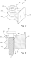
- The fact that the first attachment part is configured to be inserted into the recess in said first furniture part allowing the second attachment part to maintain its orientation about the first axis during the insertion of the first attachment part in the recess provides the advantage that the second attachment part will be oriented in the desired direction and be ready to interact with the second furniture part. This allowing the second attachment part to maintain its orientation about the first axis may according to the preferred embodiments be provided by the first attachment part being rotatable relative to the second attachment part. An example of this not forming part of the invention is e.g. shown in
Figs. 7-8 . This allowing the second attachment part to maintain its orientation about the first axis may also be provided by designing the first attachment part such that it may be inserted in any rotational orientation and still provide the desired locking effect in the interaction with the recess of the first furniture part. Examples of this latter is e.g. shown inFigs. 5-6 (not forming part of the invention) and 9-23. Another advantage of allowing the second attachment part to maintain its orientation about the first axis during the insertion of the first attachment part in the recess is that it is possible to achieve full insertion and of the first attachment part and abutment between the second attachment part and the first furniture part and still provide correct orientation of the second attachment part. - By designing the attachment part with elongated ridges oriented at an angle with its extension with a major component perpendicular to the first axis the ridges may transfer forces preventing relative motion between the attachment arrangement and the second furniture part along the first axis. By preventing relative movement along the first axis, the second furniture part, such as a shelf, may be used to hold the first furniture part, such as a sidewall of a bookshelf, in a desired position. For example, one shelf connected at its respective corners using respective attachment arrangements of the kind disclosed may be used to prevent the sidewall from bulging outwardly. The elongated ridge with its orientation also has the advantage that the ridge is easy to position correctly in the recess in the second furniture part. If the user inadvertently slides the second furniture part, e.g. the shelf, while the surface and not an intended an attachment recess is resting on the second part of the attachment arrangement, the extension of the ridge makes it possible to design it such that it provides a comparably large resting surface which minimises the risk of inadvertently damaging the underside of the second furniture part during such sliding motion. The fact that the ridge is elongated also opens up for the possibility to design it to act as a wedge to provide a strong and secure connection in the attachment recess of the second furniture part. The fact that the ridge is elongated and oriented in the mentioned orientation also opens up for the possibility to design it such that it, during the relative motion between the second furniture part and the second part of the attachment arrangement, guides the second furniture part into correct position. Thus, it is not important for the user to position the second furniture part in the exact position before the movement along second insertion direction is initiated.
- According to one preferred embodiment, the attachment arrangement is used to secure shelves to the sidewalls in a bookshelf, a wardrobe, cupboard, or the like. In such an application, the sidewall of the bookshelf is typically the first furniture part and the shelf is typically the second furniture part. The inside surface of the sidewall is typically provided with one or more recesses, such as drilled holes, extending in the first direction, said first direction being normal to the inside surface of the side wall. The first insertion direction is, hence, typically normal to the inside surface of the side wall, extends in a horizontal plane and is directed towards the surface of the side wall. The second direction is in the bookshelf application typically directed vertically downwardly. In such an application, a ridge plane is typically vertically oriented.
- The second insertion direction is according to one embodiment parallel with the direction of gravity force, i.e. directed vertically downwards. This will make the mounting easier, and will assist in holding the second furniture part in place.
- It may be noted that the attachment arrangement may be used for different kinds of applications where the orientation of e.g. the second direction or the ridge plane relative to gravity may be different than in the typical bookshelf application.
- It may be noted that it is in many cases preferred that the recess in the second furniture part does not extend all the way through the material. In the bookshelf application this means that the shelf may be provided with a smooth upper surface. It may be noted that it is possible to design the second furniture part such that the recess extends all the way through the material. It may be noted that in such a case, the feature "which top surface is adapted to face the second furniture part" is intended to be understood as the situation just before the second part of the attachment arrangement has been inserted into the recess in the second furniture part. In the first case above where the recess does not extend all the way through the second furniture part, the top surface will face the second furniture part both before and after being inserted into the recess; before insertion the top surface will face the second furniture part as such and after insertion the top surface will face the inside surface of the recess of the second furniture part.
- Preferred embodiments appear in the dependent claims defining the scope of protection and in the description.
- The first attachment part comprises an elongate member extending along the first axis, wherein the elongate member is insertable into said recess in said first furniture part by said relative motion between the first attachment part and the first furniture part in the first insertion direction in order to interact with an inside surface of the recess. This relative motion may be provided by screwing the first attachment part into the recess of the first furniture part. The relative motion may be provided by translational motion of the first attachment part into the recess of the first furniture part.
- The second attachment part is allowed to maintain its orientation about the first axis
- e.g. by the elongate member being oriented relative the second attachment part and/or provided with protrusions extending across the first axis such that an angle different from orthogonal is formed between the normal and the second axis when the elongate member is inserted into the recess in the first furniture part and whereby installation of the second furniture part forces the elongate member to deform inside walls of the recess in the first furniture part such that the angle between the normal and the second axis comes closer to orthogonal when both the first and second furniture parts are installed, and/or
- e.g. by the second attachment part being provided with a body having a through-going hole adapted to receive a screw or pin.
- The elongate member may be oriented relative the second attachment part and/or provided with protrusions extending across the first axis such that an angle of between 0,5-10°, preferably between 4-8°, different from orthogonal is formed between the normal and the second axis when the elongate member is inserted into the recess in the first furniture part and whereby installation of the second furniture part forces the elongate member to deform inside walls of the recess in the first furniture part such that the angle between the normal and the second axis comes closer to orthogonal when both the first and second furniture part are installed. This provides a strong locking effect preventing the elongate member from accidentally being pulled out of the recess in the first furniture part. In the preferred embodiment, the angle is between 5-7°.
- In one embodiment the elongate member is oriented relative to the second attachment part at an angle of between 0,5-10°, preferably between 4-8°, and most preferably between 5-7° such that, when the when the elongate member is inserted into the recess in the first furniture part, an angle of between 0,5-10°, preferably between 4-8°, less than orthogonal is formed between the normal and the second axis. The elongate member is provided with protrusions adapted to interact with the inside surface of the recess. The protrusions may be continuous or semi-continuous circular protrusions (as shown e.g. in
Figs 17-23 ), protrusions extending upwardly and opposing protrusions extending downwardly (as e.g. shown inFigs. 5-6 ) or threads around the stem of the elongate member. - The elongate member may be fixedly attached to the second attachment part. This may be provided by forming the attachment arrangement in a single piece of material, such as a polymeric material or metallic material. This may alternatively be provided by separate manufacture of the elongate member and then fixedly attaching it to the second attachment part. This latter may e.g. be performed by placing a pre-manufactured elongate part in a mould in which the second attachment part is moulded, thereby moulding a portion of the first attachment part into the second attachment part.
- The second attachment part may be provided with a body having a through-going hole adapted to receive a screw, which screw is adapted to interact, preferably threadingly interact, with an inside surface of the recess and with the body and to thereby force the body into abutment with the first furniture part thereby attaching the attachment arrangement to the first furniture part. With such a design the fact that the screw is screwed into the recess in the first furniture part provides a strong locking effect preventing the attachment arrangement from being removed from the first furniture part.
- The attachment arrangement may be provided with a lower support member adapted to abut the second furniture part, preferably to abut a lower surface of the second furniture part,, thereby aiding said at least one elongated ridge to support the second furniture part relative to the first furniture part. This is advantageous since the lower support member will transfer load onto a portion of the second furniture part having full thickness not affected by the presence of a recess adapted to receive the second attachment part. Thereby the second furniture part may be designed with limited thickness and still be able to withstand great loads.
- The attachment arrangement may be provided with a cover plate adapted to cover the recess in the second furniture part when the attachment arrangement is inserted into the recess of the second furniture part. The lower support member may be formed as a cover plate adapted to cover the recess in the second furniture part when the attachment arrangement is inserted into the recess of the second furniture part.
- The second attachment part may preferably comprise a plurality of consecutive elongate ridges, wherein each elongate ridge has a length and height arranged in an associated ridge plane, wherein each such ridge plane has a normal forming an angle to the first axis, which angle is smaller than 30°, and wherein the ridge planes are arranged successively one after another along the first axis, whereby along the first axis there is formed a set of consecutive ridges being separated by valleys arranged therebetween. A plurality of consecutive elongated ridges oriented in this manner may provide a strong force along the first axis with relatively low ridge heights which may be useful e.g. when the second furniture part has a comparably low height, such as a shelf.
- It may be noted that the ridge planes need not be parallel to each other. It is also conceivable that a single ridge follows a first ridge plane on one side of the second attachment part and another ridge plane (forming an angle with the first ridge plane) on the other side, thereby forming a V-shaped elongation (as seen in a plane to which the second axis is a normal). This may apply both for single ridge case and for a case with a plurality of consecutive ridges.
- The ridge planes associated with respective ridge of said plurality of said consecutive elongate ridges may be parallel to each other. This is facilitates e.g. manufacturing of the attachment arrangement.
- Each ridge plane may have a normal forming an angle β', β to the first axis, which angle β', β is smaller than 10°, and which angle β ' in a horizontal plane preferably is 0°. A small angle β in a vertical plane is advantageous when it comes to provide a strong holding force along the first axis. An angle β ' of 0° in a horizontal plane is advantageous since it facilitates the provision of symmetrical design. It e.g. makes it possible to provide symmetric forces on the different sides of a shelf with the use of identical attachment arrangements on all four corners.
- Each ridge may, as seen in a plane perpendicular to the ridge plane, have a wedge shaped cross-section with its width decreasing with increasing height. Such a shape is strong and also provides an automatic guiding effect as the user starts to move the second furniture part into engagement with the second attachment part.
- Each ridge may have a length such that a projection of the length onto a plane to which the second axis forms a normal is larger than, and preferably at least two times larger than, a maximum width of the ridge as seen along the first axis. This provides a distinct locking force along the first axis and still makes it possible to design the ridge with limited height, which in turn has an advantage in that it is possible to design the second furniture part with limited height and an advantage in that each ridge may be strong against shear forces along the first axis.
- Each ridge may have a length such that a projection of the length onto a plane to which the second axis forms a normal is larger than, and preferably at least two times larger than, a maximum height of the ridge. This provides a distinct locking force along the first axis and still makes it possible to design the ridge with limited height, which in turn has an advantage in that it is possible to design the second furniture part with limited height and an advantage in that each ridge may be strong against shear forces along the first axis.
- The side surfaces may be adapted to extend from the top surface in a direction having a component perpendicular to the second axis, the distance between the side surfaces increasing with increased distance from the top surface. This way the second attachment part will have a wedge effect guiding the second furniture part into correct position as the second furniture part is moved into engagement with the second attachment part.
- Each ridge may have along its length, in the ridge plane, a crest running along a curved or wedge shaped line such that a, along the length, a central portion of the crest is located at a greater height than both side portions of the crest located, along the length, on either sides of the central portion. Such a design makes good use of the available surface providing a strong locking effect along the first axis and also provides a guiding effect not only associated with the shape of the side surfaces but also associated with the shape of respective ridge.
- The second part of the attachment arrangement may comprise a body part having a portion of its surface being adapted to face the second furniture part and being formed as a convexly curved, preferably formed as a circular cylindrical, portion with its central axis extending along the normal direction, and with said at least one ridge running circumferentially on said convexly curved, preferably circular, cylindrical, portion. This is a design which provides a strong locking effect along the first axis, provides a distinct guiding effect, makes good use of the available surface and which also addresses the risk of the user damaging the second furniture part.
- The first attachment part may comprise a pin, which pin is fixedly attached to the second attachment part, which pin extends along the first axis, and which pin is insertable into said recess in said first furniture part by said relative motion between the first attachment part and the first furniture part in the first insertion direction in order to interact with an inside surface of the recess. The pin may be integrally formed with the second attachment part and of the same material. The attachment arrangement may e.g. be formed of a plastic material or of a metallic material. One suitable metallic material is e.g. Zamac. One suitable grade is e.g. Zamac 5. A suitable material may accordingly be a zinc-based alloy comprising about 94-96% zinc, about 3-5% aluminium, and optionally about 0,5-1,5% copper.
- The pin may also be of another material (such as a metal pin, preferably a steel pin) moulded into a plastic body forming at least the second attachment part of the attachment arrangement. The pin may also be added at a later stage. In such a case the second attachment part may be provided with a body having a through-going hole adapted to receive a pin.
- The pin may be oriented relative the second attachment part and/or provided with protrusions extending across the first axis such that an angle of between 0,5-10°, preferably between 4-8°, different from orthogonal is formed between the normal of the ridge plane and the second axis when the pin is inserted into the recess in the first furniture part and whereby installation of the second furniture part forces the pin to deform inside walls of the recess in the first furniture part such that the angle between the normal and the second axis comes closer to orthogonal when both the first and second furniture part are installed. This provides a strong locking effect preventing the pin from accidentally being pulled out of the recess in the first furniture part. In the preferred embodiment, the angle is between 5-7°.
- The through-going hole and the there-through extending pin or screw may be complemented with guiding pins adapted to extend into the recess into which the first attachment part is adapted to extend or into other holes in the first furniture part separate from the recess. The guiding pins may e.g. be two or more tongues extending in parallel in the first direction with the pin or screw being adapted to extend between the tongues. The tongues may e.g. act as a plug frictionally engaging with the inside surface of the recess when a screw is screwed into the recess between the tongues or when a pin is forced through the through-going hole and between the tongues. This latter design is e.g. useful if the first furniture part is formed of comparably soft material, such as fibre board or the like. As mentioned above the screw or pin may engage directly with the inside surface of the recess.
- The pin may be provided with one or more protrusions extending at least partly across the first axis and being adapted to interact with an inside surface of the recess, the protrusions thereby forming barbs counter-acting removal of the attachment arrangement from the first furniture part.
- The protrusions or barbs may extend around a part of the circumference of the pin, or be discrete and distributed completely, as rings, around the circumference of the pin thereby counter-acting removal once the pin has been inserted into the recess.
- In one preferred embodiment, the pin is, on a portion adapted to be located deeper inside the recess, provided with one or more protrusions or barbs located on only a part of the circumference of the pin being adapted to face a direction opposite the second insertion direction, and is, on a portion adapted to be located closer to the mouth of the recess, provided with one or more protrusions or barbs located only on a part of the circumference of the pin being adapted to face along the second insertion direction. With this latter design, the pin will be forced into a locked position counter-acting removal when the second furniture part is installed and also when the second furniture is loaded in the second direction, e.g. by supporting books, whereas the pin may still easily be removed during dismantling of the furniture. This latter may e.g. be useful if the user desires to change the vertical position of a shelf.
- The second furniture part may be provided with an attachment recess having at least one elongate valley extending in a valley plane being parallel to the associated ridge plane of the second attachment part, the respective valley being adapted to interact with an associated ridge of the attachment arrangement thereby counteracting relative motion between the attachment arrangement and the second furniture part along the first axis.
- Said at least one ridge of the attachment arrangement may be adapted to be positioned relative to the position of said at least one valley of the second furniture part and relative the position of an abutment portion of the attachment arrangement by which the attachment arrangement abuts the first furniture part such that the second furniture part is forced into interference fit along the first axis as the second attachment part and the second furniture part are moved towards each other along the second insertion direction. This provides a distinct effect of stabilising the first and second furniture parts relative to each other.
- This may alternatively be expressed as that a ridge plane associated with a valley plane is located closer to the first furniture part when the attachment arrangement is positioned relative the first furniture part and the second furniture part is in initial abutment with the first furniture part but not fully moved towards the attachment arrangement. Thereby the further or final movement of the second furniture part towards the attachment part will cause the ridge plane and valley plane to move towards each other and typically ultimately coincide and the second furniture part being forced into interference fit with the first furniture part.
- The attachment recess and the second attachment part may be adapted for, during mounting, to cause a sliding-in movement of said at least one ridge of the attachment arrangement into said at least one valley of the attachment recess of the second furniture part to cause the second furniture part to be pressed against the first furniture part during mounting, such that said interference fit is achieved.
- In a preferred embodiment the second furniture part is provided with an attachment recess having a plurality of consecutive elongate valleys each extending in a valley plane being parallel to the associated ridge plane, the respective valley being adapted to interact with an associated ridge of the attachment arrangement thereby counteracting relative motion between the attachment arrangement and the second furniture part along the first axis. The valleys of the recess in the second furniture part may form along the first axis a set of consecutive valleys being separated by ridges arranged therebetween. In a preferred embodiment the valleys are complementary in shape to the ridges on the second attachment part of the attachment arrangement.
- The attachment recess may be provided with a waist separating an entrance part of the attachment recess from a locking part of the attachment recess, preferably the second attachment part being adapted for passing the waist upon being pressed thereagainst, the waist being adapted for holding the second attachment part locked in the locking part in accordance with snap-action function, as the waist has a more narrow cross-section, to be passed by the second attachment part, than the locking part. This provides a distinct information to the user concerning correct attachment and it also aids in keeping the shelf in place.
- The invention will by way of example be described in more detail with reference to the appended schematic drawings, which shows a presently preferred embodiment of the invention.
-
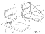
Fig. 1 shows a cupboard or bookshelf laid on a side wall with the self extending upwardly in a state before any of the parts are assembled. -
Fig. 2 corresponds toFig. 1 and shows a state where the attachment arrangements are inserted into the recesses of the inside surface of the side wall.Fig. 2b is a cross-section of an example not forming part of the invention, corresponding toFig. 2. Fig. 2c is a cross-section of an another example not forming part of the invention. -
Fig. 3 corresponds toFigs. 1 and2 and shows an assembled state with the shelf moved into position onto the attachment arrangement. -
Figs. 4-6 show an attachment arrangement according to an example not forming part of the invention. -
Figs. 7-8 show an attachment arrangement according to an example not forming part of the invention. -
Figs. 9-11 show an attachment arrangement according to an embodiment. -
Fig. 12 is a detailed view of the recess in the first furniture part and an attachment arrangement exemplified by an attachment arrangement. -
Fig. 13 is a top plan view of the second attachment part exemplified by an attachment arrangement not forming part of the invention. -
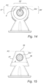
Figs. 14 and 15 disclose alternative examples of the second attachment part exemplified as alternatives to the attachment arrangement. -
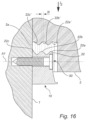
Fig. 16 shows attachment of a second furniture part to a first furniture part involving interference fit. -
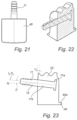
Figs. 17-23 show an attachment arrangement according to an embodiment and alternatives thereof inFigs. 20b-20c . - In
Figs. 1-3 , there is disclosed anattachment arrangement 10 adapted to connect afirst furniture part 1 to asecond furniture part 2. As shown in more detail e.g. inFig. 5 , the attachment arrangement comprises: afirst attachment part 11 adapted to be inserted into arecess 1a, 1b (Fig. 1 ) in saidfirst furniture part 1 by a relative motion between thefirst attachment part 11 and thefirst furniture part 1 in a first insertion direction I1 extending along a first axis A1, and asecond attachment part 22 adapted to be inserted into arecess second furniture part 2 by a relative motion between on one hand thesecond furniture part 2 and on the other hand theattachment arrangement 22 in a second insertion direction I2 extending along a second axis A2. In its widest implication the second axis A2 has at least a major component orthogonal to the first axis A1. In this example, the first axis A1 is orthogonal to the second axis A2 (as e.g. shown inFigs. 1 ,2 and 2b ). InFig. 2c there is shown a design where the first axis A1 extends at an angle γ relative to an imaginary direction (indicated by the dashed line A1') along which imaginary direction the first axis A1 would be orthogonal to the second axis A2. This angle γ may be a small angle e.g. taking into account that, when thesecond furniture part 2 is loaded (indicated by arrow F), thefirst attachment part 11 may have a tendency to move inside or deform the inside of the recess 1a thereby slightly changing the orientation of theattachment arrangement 10 relative to the first furniture part (indicated by arrow RF). The angle γ may e.g. be chosen such that when the first andsecond furniture parts first attachment part 11 becomes orthogonal to the loading direction F. - As shown e.g. in
Fig. 5 , thesecond attachment part 2 comprises a plurality of consecutiveelongated ridges 22a-c, wherein each elongate ridge has a length L (seeFig. 4 ) and a height H extending in an associated ridge plane PR1, PR2, PR3. The ridge planes PR1, PR2, PR3 are arranged successively one after another along the first axis A1, whereby along the first axis A1 there is formed a set ofconsecutive ridges 22a-c being separated by valleys 23a-b arranged therebetween. - The height H is indicated in a cross-sectional view in
Fig. 6 . In the preferred embodiment the height H has the same value for allridges 22a-c measured orthogonal to the length L at any given point along the length L. It may be noted that the height H may be different at different points along the length L forrespective ridge 22a-c. This is e.g. indicated by the arrows H1 and H2 inFig. 4 andFig. 5 , where e.g. height H1 may be greater than height H2 or vice versa. It may also be noted that the height H may be different fordifferent ridges 22a-c at corresponding points along the length L. This is e.g. indicated by the arrows H1 and H3 inFig. 4 andFig. 5 , where e.g. height H1 may be greater than height H3 or vice versa. - It is preferred that the height H measured orthogonally to the length L is the same along the length L of respective ridge and also the same for all of the ridges, since this facilitates production of the
second attachment part 22 of theattachment arrangement 10 and also facilitates the production of therecess second furniture part 2. Typically, therespective recess second furniture part 2 is produced by a milling operation whereby it is convenient to use a milling tool producing the profile of the valleys. Typically, theattachment arrangement 10 is casted or moulded and the tool used in such casting or moulding is conveniently produced using a milling operation. The length L is shown as extending along the curved path inFig. 4 . InFig. 4 , the ridge planes PR1, PR2, PR3 are parallel to the plane of the paper. InFig. 13 , the projection L' of the length L onto the plane of the paper ofFig. 13 is shown. The length L along the curved path is the active length, i.e. the length over which any force along the first axis A1 is transmitted between thesecond attachment part 22 of theattachment arrangement 10 and thesecond furniture part 2. It is preferred that theridges 22a-c have the same active length L but it is conceivable thatdifferent ridges 22a-c have different active lengths L. - As shown in
Fig. 13 andFig. 6 , the ridge planes PR1, PR2, PR3 have normals N extending in parallel, or at least essentially in parallel, with the first axis A1 at least when thefirst furniture part 1, thesecond furniture part 2 and theattachment arrangement 10 is in the assembled state. In this assembled state it is also conceivable that the ridge planes PR1, PR2, PR3 are slanted relative the first direction I1 such that the normal N (pointing towards the first furniture part 1) forms and angle β with the first direction I1 being smaller than 30°, preferably smaller than 10°. - It may be noted that the ridge planes PR1, PR2, PR3 need not be parallel to each other. It is also conceivable that a single ridge follows a first ridge plane on one side of the second attachment part and another ridge plane (forming an angle with the first ridge plane) on the other side, thereby forming a V-shaped elongation (as seen in a plane to which the second axis is a normal). This may apply both for single ridge case and for a case with a plurality of consecutive ridges. As shown in the embodiments of
Figs. 6 and13 , the ridge planes PR1, PR2, PR3 are parallel to each other and theridges 22a-c extend on both sides of the centre line. - In the
Figs. 1-12 andFigs. 16-23 , the elongated ridges are formed on both top and side surfaces of thesecond attachment part 22. It may be noted that in theFigs. 1-12 andFigs. 16-23 , the top surface and side surfaces are in fact a continuous curved surface. In this context it may be noted that the top surface 25' is a part of the surface of thesecond attachment part 22 adapted to face thesecond furniture part 2 and the side surfaces 26', 27' are the parts of the surface adapted to extend from the top surface 25' in a direction having a component along the second insertion direction I2. The surface of thesecond attachment part 22 may be broken into different segments having different curvatures. The surface of thesecond attachment part 22 may be broken into different segments extending along straight lines with different angles. Such designs are generally indicated byFigs. 14 and 15 . InFig. 14 , thesecond attachment part 22 of theattachment arrangement 10 is basically formed in the same manner as in the embodiments inFigs. 1-13 andFigs. 16-23 , but a top portion is cut away along a cutting plane PC. The cutting plane PC has in the shown embodiment its normal NPC in parallel to the second insertion direction I2. It is conceivable that the normal NPC forms an angle with the second direction being smaller than 30°. - The
attachment arrangement 10 is e.g. used to secureshelves 2 to thesidewalls 1 in a bookshelf, a wardrobe, a cupboard, or the like as indicated inFigs. 1-3 . In such an application, the sidewall of the bookshelf is typically thefirst furniture part 1 and the shelf is typically thesecond furniture part 2. The inside surface of the sidewall is typically provided with one ormore recesses 1a, 1b, such as drilled holes, extending along the first axis A1, said first axis A1 being normal to the inside surface of the side wall. When the bookshelf is assembled and positioned in correct position for use, the first insertion direction is, hence, typically normal to the inside surface of the side wall, extends in a horizontal plane and is directed towards the surface of the side wall. The second direction is in the bookshelf application typically directed vertically downwardly. In such an application, the ridge plane is typically vertically oriented and in the preferred embodiments also parallel to the sidewalls. - As mentioned above, the bookshelf shown in
Figs. 1-3 is shown as being laid down onto its side with thesidewall 1 on a floor. This orientation is chosen to be able to show the different parts. When using theattachment arrangement 10 to attachfurniture parts - It is e.g. conceivable that the frame of the furniture is assembled and positioned in an upright standing position with the
sidewalls 1 extending vertically. The first insertion direction I1 would in such a case extend horizontally and the second insertion direction I2 would extend vertically downwardly. - It is also conceivable that the bookshelf is assembled and is kept laying with its
backside 3 on the floor. The first insertion direction I1 would in such a case extend horizontally and the second insertion direction I2 would also extend horizontally, albeit orthogonally to the first direction I1. - It may be noted that the
attachment arrangement 10 may be used for different kinds of applications where the orientation of e.g. the second direction or the ridge plane relative to gravity may be different than in the typical bookshelf application. - As shown in
Fig. 12 , therecess 2a in thesecond furniture part 2 does not extend all the way through the material. In the bookshelf application this means that theshelf 2 may be provided with a smoothupper surface 21. It may be noted that it is possible to design thesecond furniture part 2 such that the recess extends all the way through the material. It may be noted that in such a case, the feature "which top surface is adapted to face the second furniture part" is intended to be understood as the situation just before the second part of the attachment arrangement has been inserted into the recess in the second furniture part. It is e.g. conceivable to use anattachment arrangement 1 according toFigs. 14 or 15 with the cutting plane PC in flush with the upper surface of the shelf. In the first case above where therecess 2a does not extend all the way through thesecond furniture part 2, the top surface of thesecond attachment part 22 will face thesecond furniture part 2 both before and after being inserted into therecess 2a; before insertion the top surface will face the second furniture part as such and after insertion the top surface will face the inside surface of the recess of the second furniture part. - As shown in
Fig. 12 , theattachment recess 2a is provided with awaist 2a' separating anentrance part 2a" of theattachment recess 2a from a lockingpart 2a‴ of theattachment recess 2a, wherein thesecond attachment part 22 is adapted for passing thewaist 2a' upon being pressed thereagainst, and wherein thewaist 2a' is adapted for holding thesecond attachment part 22 locked in the lockingpart 2a‴ in accordance with snap-action function. The snap-in effect occurs when thesecond attachment part 22 passes the waist, seeFig. 12 , and enters from the (lower)entrance part 2a" and up into the lockingpart 2a‴ of theattachment recess 2a, as thewaist 2a' has a more narrow cross-section, to be passed by thesecond attachment part 22, than the lockingpart 2a‴. - As shown in the figures, see e.g.
Fig. 6 andFig. 13 , each ridge has as seen in a plane perpendicular to the ridge plane PR1, PR2, PR3, a wedge shaped cross-section with its width W decreasing with increasing height H. - As shown in
Figs. 4 and13 , eachridge 22a-c has a length L such that a projection L' of the length L onto a plane (plane of the paper inFig. 13 ) to which the second axis A2 forms a normal, is larger than, and preferably at least two times larger than, a maximum width MW of theridge 22a-c as seen along the first axis A1, i.e. L' > MW, preferably L' => 2*MW. It may be noted in this context that the height H of a ridge is measured from the lowest point between two adjacent ridges to the highest point of respective ridge. This is shown inFigs. 6 and13 . The width MW of oneridge 22a-c is measured from the point where the ridge falls down towards one valley at half the height H (i.e. H/2) of aridge 22a-c to the other point on the other side of theridge 22a-c where the ridge falls down towards one valley at half the height H (i.e. H/2). This is shown inFig. 6 andFig. 13 . - As shown in
Fig. 13 , eachridge 22a-c has a length L, best shown inFig. 4 , such that a projection L' of the length onto a plane (plane of the paper ofFig. 13 ) to which the second axis A2 forms a normal is larger than, and preferably at least two times larger than, a maximum height H of theridge 22a-c, i.e. L' > H, preferably L' => 2*H. - In all the embodiments, the side surfaces 26, 26', 27, 27' of the
second attachment part 22 extend from thetop surface 25, 25' in a direction having a component across the second axis in a direction adapted to face the recess of the second furniture part such that a distance d between the side surfaces increases with increased distance from the top surface. InFig. 15 , there is a distinct flattop surface 25 and straight side surfaces 26 and 27. InFig. 15 , thetop surface 25 is not provided with ridges but it is contemplated that thetop surface 25 may alternatively also be provided with ridges. The above is also true for a curved or partly circular design. If there is a ridge also on the top surface, each ridge will have along its length, in the ridge plane, a crest running along a curved or wedge shaped line such that a, along the length, a central portion 25' of the crest is located at a greater height than both side portions 26', 27' of the crest located, along the length, on either sides of the central portion. Such a design makes good use of the available surface providing a strong locking effect along the first axis and also provides a guiding effect not only associated with the shape of the side surfaces but also associated with the shape of respective ridge. - In
Figs. 1-13 and16-23 , thesecond attachment part 22 comprises a body part 22' having a portion of its surface being adapted to face the second furniture part and being formed as a convexly curved, preferably formed as a circular cylindrical portion with its central axis extending along the first axis A1, and with said at least one ridge running circumferentially on said convexly curved, preferably circular, cylindrical portion. - As shown in
Figs. 5, 6 and13 , thefirst attachment part 11 comprises apin 12. Thepin 12 is fixedly attached to thesecond attachment part 12 and extends along the first axis A1. Thepin 12 is insertable into saidrecess 1a, 1b in thefirst furniture part 1 by the relative motion between thefirst attachment part 11 and thefirst furniture part 1 in the first insertion direction I1 in order to interact with an inside surface of therecess 1a, 1b. - As shown in
Fig. 5, 6 , and13 , thepin 12 is typically integrally formed with thesecond attachment part 22 and of the same material. Theattachment arrangement 10 may e.g. be formed of a plastic material or of a metallic material. One suitable metallic material is e.g. Zamac. One suitable grade is e.g. Zamac 5. A suitable material may accordingly be a zinc-based alloy comprising about 94-96% zinc, about 3-5% aluminium, and optionally about 0,5-1,5% copper. - The pin may also be of another material (such as a metal pin, preferably a steel pin) than the
second attachment part 22 and may be moulded into a plastic body forming other parts of the attachment arrangement. The pin may also be added at a later stage. In such a case the second attachment part may be provided with a body having a through-going hole adapted to receive a pin. Thehole 29 may be circular or may be designed withinternal grooves 29a extending along the centre line of thehole 29 in order to secure the pin at a specific rotational orientation. Such ahole 29 withinternal grooves 29a is shown in the embodiment shown inFigs. 9-11 . - As shown in
Fig. 11 , thehole 29 may be inclined with the intention of orienting an insertable pin12 at an angle α relative thesecond attachment part 22. Thepin 12 may be provided partly inserted into thesecond attachment part 22 as shown inFig. 11 . This has the advantage that the user does not need to keep track of two pieces and there is no risk that the user inserts thepin 12 incorrectly into thesecond attachment part 22. Thepin 12 may be provided partly inserted into thesecond attachment part 22 to such an extent that the tip extends a short distance out of thesecond attachment part 22 as indicated by the dashed lines inFig. 11 . This has the advantage that the user may easily position the attachment arrangement correctly relative to the first recess 1a-b in thefirst furniture part 1 before pushing or striking the pin with a hammer and thereby fully inserting the pin into the recess 1a-b of thefirst furniture part 1. As shown inFigs. 5 and 6 , thepin 12 may be provided withprotrusions 12a-c extending across the first axis A1. - The
protrusions 12a-c (Fig. 6 ), and/or the pin itself (e.g.Fig. 11 ,Fig. 17 ) may be oriented such that an angle α (seeFig. 11 ) of between 0,5-10°, preferably between 4-8°, less than or different from orthogonal is formed between the normal N and the second axis A2 when thepin 12 is inserted into the recess 1a-b in thefirst furniture part 1 and whereby installation of thesecond furniture part 2 forces thepin 12 to deform inside walls of the recess 1a-b in thefirst furniture part 1 such that the angle α becomes closer to 0° and the angle between the normal N and the second axis A2 comes closer to orthogonal, and preferably becomes orthogonal, when both the first andsecond furniture parts pin 12 from accidentally being pulled out of the recess 1a-b of thefirst furniture part 1. In the preferred embodiment, the angle α is about 5-7, most preferably 6°. - As shown in
Fig. 6 andFig. 11 discussed above, thefirst attachment part 11 may be an elongate member orpin 12 provided with a plurality of protrusions 12d-g. The protrusions 12d-g disclosed inFigs. 17-23 are shown as circular rings around a stem. It may be noted that the circular rings 12d-g need not be fully continuous around the stem. As alternative to the rings, the protrusions 12d-g may be formed of one or more continuous or semi-continuous thread(-s) forming rings extending around the stem. As shown inFigs. 17-23 and as e.g. shown inFig. 19 , at least one of the rings, and preferably all the rings, may have a forward sloping guiding surface 12g" and a rearward locking surface 12g'. The guiding surface 12g" has an increasing radial extension towards thesecond attachment part 22. The locking surface 12g' forms a distinct step thereby providing a locking effect. In the embodiment ofFigs. 17-23 , theelongate member 12 has a main extension along a first axis A1, which will also be along which axis A1 and direction I1 theelongate member 12 is inserted into thefirst furniture part 1. This main extension is in this embodiment angled at an angle β relative to the normal N of the ridge planes. The angle β is in this embodiment about 0,5-10°, preferably between 4-8°. This will in turn result in that an angle α of between 0,5-10°, preferably between 4-8°, different from orthogonal is formed between the normal N and the second axis A2 when theelongate member 12 is inserted into the recess 1a-b in thefirst furniture part 1. Installation of thesecond furniture part 2 will force theelongate member 12 to deform the inside walls of the recess 1a-b in thefirst furniture part 1 such that the angle α, by which extensions of the normal N and the second axis A2 differs from orthogonal, comes closer to zero and the normal N and second axis A2 comes closer to orthogonal when both the first andsecond furniture parts - It may be noted that the angle between the insertion direction I1 and the normal N to the ridge planes PR1, PR2, PR3 may not only be in the plane formed by the first and second directions I1 and I2, but may also as a complement or alternative be in a plane formed by the first direction I1 and a third direction orthogonal to the first and second directions. This plane would basically be the plane of the paper of
figure 20b . InFig. 20b it is shown how the longitudinal extension I1, A1 of theelongate member 12 is angled an angle β' of about 15° relative to thesecond attachment part 22 and thereby to the normal N of the ridge planes PR1, PR2, PR3. InFig. 20c it is shown how the ridge planes PR1, PR2, PR3 are angled an angle β' of about 15° relative to thesecond attachment part 22 and thereby to the longitudinal extension I1, A1 of theelongate member 12. In the preferred embodiment shown inFig. 20a , there is no angle β' between the first direction I1, A1 and the normal N of the ridge planes PR1, PR2, PR3. However, as discussed in relation toFig. 19 , there is an angle β in the plane defined by the first and second directions I1, I2. - In the alternative shown in
Figs. 7 and 8 , thesecond attachment part 22 is provided with a body 22' having a through-goinghole 29 adapted to receive ascrew 30, which screw 30 is adapted to interact, preferably threadingly interact, with an inside surface of the recess1a, 1b and with the body 22' and to thereby force the body 22' into abutment with thefirst furniture part 1 thereby attaching theattachment arrangement 10 to thefirst furniture part 1. With such a design the fact that the screw is screwed into the recess 1a-b provides a strong locking effect preventing theattachment arrangement 10 from being removed from thefirst furniture part 1. Thehead 31 of thescrew 30 is adapted to interact with anabutment portion 24 of the through-goinghole 29. - The pin may be provided with one or more protrusions extending at least partly across the first axis and being adapted to interact with an inside surface of the thereby forming barbs counter-acting removal of the
attachment arrangement 10 from thefirst furniture part 1. One example of such barbs are theprotrusions 12a-c shown inFig. 6 also having the effect of providing a specific orientation. - In
Fig. 6 , theprotrusions 12a-c are distributed such that on a portion adapted to be located deeper inside the recess there is provided one or more protrusions orbarbs 12a-b located only on that part of the circumference of thepin 12 which is adapted to face a direction opposite the second insertion direction I2, and, on a portion adapted to be located closer to the mouth of the recess 1a-b, there is provided one or more protrusions or barbs 12c located only on that part of the circumference of thepin 12 which is adapted to face along the second insertion direction I2. With this latter design, the pin will be forced into a locked position counter-acting removal when thesecond furniture part 2 is installed and also when thesecond furniture part 2 is loaded in the second direction A2, e.g. by supporting books, whereas the pin may still easily be removed from thefirst furniture part 1 during dismantling of the furniture. This latter may e.g. be useful if the user desires to change the vertical position of a shelf. - As shown in the figures, see for example
Figs. 3 and5 andFigs. 17-23 , theattachment arrangement 10 is provided with alower support member 40. Thelower support member 40 is provided with anabutment surface 40a extending outwardly in a plane P40 defined by the first direction I1 and a third direction I3 orthogonal to the first and second directions past a projection of theridges 22a-c onto said plane P40. Thereby an outer portion of thesurface 40a along the perimeter of thesupport member 40 may abut thefirst furniture part 1 outside therespective recess 1a, 1b. The distance D40a between the top of theridges 22a-c and theabutment surface 40a is preferably chosen such that any force onto thesecond furniture part 2, such as the weight of books or the like, is partly carried by the interaction between thesecond attachment part 22 and the inside of therecess 2a-b and partly carried by the interaction between theabutment surface 40a and the portions of thesecond furniture part 2 surrounding therecess 2a-b. Thelower support member 40 is shaped as acover plate 40 adapted to cover therecess 2a-b in thesecond furniture part 2 when theattachment arrangement 10 is inserted into therecess 2a-b of thesecond furniture part 2. Hence, thelower support member 40 may have the dual function of supporting thesecond furniture part 2 and of covering therecess 2a-b. - As shown in
Fig. 23 , thefirst attachment part 11 may be designed as a separateelongate member 12 moulded into thesecond attachment part 22, wherein the latter is preferably integrally formed with thelower support member 40. Thefirst attachment part 11 may e.g. be made of a metal material which is moulded into a polymer material forming thesecond attachment part 22. Thefirst attachment part 11 may be provided with ahead 11a having a larger cross-section than thestem 11b thereby reducing the risk of accidental removal of thefirst attachment part 11 from thesecond attachment part 22. - The
second furniture part 2 is provided with anattachment recess 2a-b having at least oneelongate valley 22a-c' extending in a valley plane PV being parallel to the associated ridge plane PR1, PR2, PR3, therespective valley 22a'-c' being adapted to interact with an associatedridge 22a-c of theattachment arrangement 10 thereby counteracting relative motion between theattachment arrangement 10 and thesecond furniture part 2 along the first axis A1. This is indicated inFig. 12 . Basically all the features and discussions related to theridges 22a-c of theattachment arrangement 10 may be transferred to the associatedvalleys 22a'-c' of theattachment recess 2a-b of thesecond furniture part 2. - As illustrated in
Fig. 16 , theridges 22a-c of theattachment arrangement 10 are adapted to be positioned relative to the position of thevalleys 22a'-c' of thesecond furniture part 2 and relative the position of anabutment portion 50 of theattachment arrangement 10 by which theattachment arrangement 10 abuts thefirst furniture part 1 such that thesecond furniture part 2 is forced into interference fit (ip) along the first axis A1 as thesecond attachment part 22 and thesecond furniture part 2 are moved towards each other along the second insertion direction I2. Theattachment recess 2a and thesecond attachment part 22 are adapted for, during mounting, to cause a sliding-in movement of said at least oneridge 22a-c of theattachment arrangement 10 into said at least onevalley 22a'-c' of theattachment recess 2a of thesecond furniture part 2 to cause thesecond furniture part 2 to be pressed against thefirst furniture part 1 during mounting, such that said interference fit is achieved.
Claims (15)
- A piece of furniture comprising an attachment arrangement (10) and a second furniture part (2), said attachment arrangement (10) being adapted to connect a first furniture part (1) to the second furniture part (2), the attachment arrangement (10) comprising:a first attachment part (11) adapted to be inserted into a recess (1a-b) in said first furniture part (1) by a relative motion between the first attachment part (11) and the first furniture part (1) in a first insertion direction (I1) extending along a first axis (A1), anda second attachment part (22) adapted to be inserted into a recess (2a-b) in said second furniture part (2) by a relative motion between on one hand the second furniture part (2) and on the other hand the attachment arrangement (10) in a second insertion direction (I2) extending along a second axis (A2), the second axis (A2) having at least a major component orthogonal to the first axis (A1),wherein the second attachment part (22) comprises at least one elongated ridge (22a-c) having a length (L) and a height (H) and extending in a ridge plane (PR1, PR2, PR3),wherein the ridge plane (PR1, PR2, PR3) has a normal (N) forming an angle (β, β') to the first axis (A1), which angle is smaller than 30° and the first axis (A1) is inclined with regards to the normal (N),wherein said at least one elongated ridge (22a-c) is formed on top (25, 25') and/or on side surfaces (26, 27, 26', 27') of the second attachment part (22), which top surface (25, 25') is adapted to face the second furniture part (2) and which side surfaces (26, 27, 26', 27') are adapted to extend from the top surface (25, 25') in a direction having a component which is parallel with the second insertion direction (I2), andwherein the first attachment part (11) is configured to be inserted into the recess (1a-b) in said first furniture part (1) allowing the second attachment part (22) to maintain its orientation about the first axis (A1) during the insertion of the first attachment part (11) in the recess (1a-b),wherein the first attachment part (11) comprises an elongate member (12) extending along the first axis (A1), wherein the elongate member (12) is insertable into said recess (1a-b) in said first furniture part (1) by said relative motion between the first attachment part (11) and the first furniture part (1) in the first insertion direction (I1) in order to interact with an inside surface of the recess (1a-b),and wherein the second attachment part (22) is allowed to maintain its orientation about the first axis (A1)by the elongate member (12) being oriented relative the second attachment part (22) and/or provided with protrusions (12a-c) extending across the first axis (A1) such that an angle different from orthogonal is formed between the normal (N) and the second axis (A2) when the elongate member (12) is inserted into the recess (1a-b) in the first furniture part (1) and whereby installation of the second furniture part (2) is able to force the elongate member (12) to deform inside walls of the recess (1a-b) in the first furniture part (1) such that the angle between the normal (N) and the second axis (A2) comes closer to orthogonal when both the first and second furniture parts (1, 2) are installed.
- A piece of furniture according to claim 1, wherein the elongate member (12) is oriented relative the second attachment part (22) and/or provided with protrusions (12a-c) extending across the first axis (A1) such that an angle (α) of between 0,5-10°, preferably between 4-8°, different from orthogonal is formed between the normal (N) and the second axis (A2) when the elongate member (12) is inserted into the recess (1a-b) in the first furniture part (1) and whereby installation of the second furniture part (2) is able to force the elongate member (12) to deform inside walls of the recess (1a-b) in the first furniture part (1) such that the angle between the normal (N) and the second axis (A2) comes closer to orthogonal when both the first and second furniture parts (1, 2) are installed, and wherein preferably the elongate member (12) is fixedly attached to the second attachment part (22).
- A piece of furniture according to any one of claims 1-2, wherein the second attachment part (22) is provided with a body (22') having a through-going hole (29) adapted to receive a screw (30), which screw (30) is adapted to interact with an inside surface of the recess (1a-b) and with the body (22') and to thereby force the body (22') into abutment with the first furniture part (1) thereby attaching the attachment arrangement (10) to the first furniture part (1).
- A piece of furniture according to any one of claims 1-3, wherein the attachment arrangement (10) is provided with a lower support member (40) adapted to abut the second furniture part (2), preferably to abut a lower surface of the second furniture part (2), thereby aiding said at least one elongated ridge (22a-c) to support the second furniture part (2) relative to the first furniture part (1) and wherein preferably the lower support member (40) is formed as a cover plate (40) adapted to cover the recess (2a-b) in the second furniture part (2) when the attachment arrangement (10) is inserted into the recess (2a-b) of the second furniture part (2).
- A piece of furniture according to any one of claims 1-4, wherein the second attachment part (22) comprises a plurality of consecutive elongate ridges (22a-c), wherein each elongate ridge (22a-c) has a length (L) and height (H) arranged in an associated ridge plane (PR1, PR2, PR3), wherein each such ridge plane has a normal (N) forming an angle to the first axis (A1), which angle is smaller than 30°, and the first axis (A1) is inclined with regards to the normal (N), and wherein the ridge planes are arranged successively one after another along the first axis (A1), whereby along the first axis there is formed a set of consecutive ridges (22a-c) being separated by valleys (23a-b) arranged therebetween, and
wherein preferably the ridge planes (PR1, PR2, PR3), each being associated with a respective ridge (22a-c) of said plurality of said consecutive elongate ridges, are parallel to each other. - A piece of furniture according to any one of claims 1-5, wherein each ridge plane (PR1, PR2, PR3) has a normal (N) forming an angle to the first axis (A1), which angle is smaller than 10°.
- A piece of furniture according to any one of claims 1-6, wherein each ridge (22a-c) has, as seen in a plane perpendicular to the ridge plane (PR1, PR2, PR3), a wedge shaped cross-section with its width (W) decreasing with increasing height (H) and
wherein preferably each ridge (22a-c) has a length (L) such that a projection (L') of the length (L) onto a plane to which the second axis (A2) forms a normal is larger than, and preferably at least two times larger than, a maximum width (MW) of the ridge (22a-c) as seen along the first axis (A1). - A piece of furniture according to any one of claims 1-7, wherein each ridge (22a-c) has a length (L) such that a projection (L') of the length (L) onto a plane to which the second axis (A2) forms a normal is larger than, and preferably at least two times larger than a maximum height (H) of the ridge.
- A piece of furniture according to any one of claims 1-8, wherein the side surfaces (26, 27) are adapted to extend from the top surface (25) in a direction having a component being perpendicular to the second axis (A2), the distance (d) between the side surfaces increasing with increased distance from the top surface.
- A piece of furniture according to any one of claims 1-9, wherein each ridge (22a-c) has along its length (L), in the ridge plane (PR1, PR2, PR3), a crest (25, 25', 26, 26', 27, 27') running along a curved or wedge shaped line such that a, along the length (L), a central portion of the crest (25, 25') is located at a greater height than both side portions (26, 26', 27, 27') of the crest located, along the length (L), on either sides of the central portion.
- A piece of furniture according to any one of claims 1-10, wherein the second attachment part (22) further comprising a body part (22') having a portion of its surface being adapted to face the second furniture part (2) and being formed as a convexly curved, preferably formed as a circular cylindrical portion with its central axis extending along the normal direction (N), and with said at least one ridge (22a-c) running circumferentially on said convexly curved, preferably circular, cylindrical portion.
- A piece of furniture according to any preceding claims, further comprising a first furniture part (1).
- A piece of furniture according to any preceding claim, wherein the second furniture part (2) is provided with an attachment recess (2a-b) having at least one elongate valley (22a'-c') extending in a valley plane (PV) being parallel to the associated ridge plane (PR1, PR2, PR3), the respective valley (22a'-c') being adapted to interact with an associated ridge (22a-c) of the attachment arrangement (10) thereby counteracting relative motion between the attachment arrangement (10) and the second furniture part (2) along the first axis (A1).
- A piece of furniture according to claim 13, wherein said at least one ridge (22a-c) of the attachment arrangement (10) is adapted to be positioned relative to the position of said at least one valley (22a'-c') of the second furniture part (2) and relative the position of an abutment portion (50) of the attachment arrangement (10) by which the attachment arrangement (10) abuts the first furniture part (1) such that the second furniture part (2) is forced into interference fit (ip) along the first axis (A1) as the second attachment part (22) and the second furniture part (2) are moved towards each other along the second insertion direction (I2) and
wherein preferably the attachment recess (2a) and the second attachment part (22) are adapted for, during mounting, to cause a sliding-in movement of said at least one ridge (22a-c) of the attachment arrangement (10) into said at least one valley (22a'-c') of the attachment recess (2a) of the second furniture part (2) to cause the second furniture part (2) to be pressed against the first furniture part (1) during mounting, such that said interference fit (ip) is achieved. - A piece of furniture according to any one of the preceding claims, wherein the attachment recess (2a-b) is provided with a waist (2a') separating an entrance part (2a") of the attachment recess (2a-b) from a locking part (2a‴) of the attachment recess (2a-b), preferably the second attachment part (22) being adapted for passing the waist (2a') upon being pressed thereagainst, the waist (2a') being adapted for holding the second attachment part (22) locked in the locking part (2a‴) in accordance with snap-action function.
Applications Claiming Priority (2)
| Application Number | Priority Date | Filing Date | Title |
|---|---|---|---|
| SE1551662A SE540554C2 (en) | 2015-12-16 | 2015-12-16 | Attachment arrangement and piece of furniture |
| PCT/SE2016/051257 WO2017105324A1 (en) | 2015-12-16 | 2016-12-14 | Attachment arrangement and piece of furniture |
Publications (3)
| Publication Number | Publication Date |
|---|---|
| EP3390845A1 EP3390845A1 (en) | 2018-10-24 |
| EP3390845A4 EP3390845A4 (en) | 2019-07-10 |
| EP3390845B1 true EP3390845B1 (en) | 2025-03-26 |
Family
ID=59057123
Family Applications (1)
| Application Number | Title | Priority Date | Filing Date |
|---|---|---|---|
| EP16876149.2A Active EP3390845B1 (en) | 2015-12-16 | 2016-12-14 | Piece of furniture |
Country Status (5)
| Country | Link |
|---|---|
| US (1) | US10716401B2 (en) |
| EP (1) | EP3390845B1 (en) |
| CN (1) | CN108700102B (en) |
| SE (1) | SE540554C2 (en) |
| WO (1) | WO2017105324A1 (en) |
Families Citing this family (12)
| Publication number | Priority date | Publication date | Assignee | Title |
|---|---|---|---|---|
| BE1022567B1 (en) * | 2014-10-31 | 2016-06-07 | Unilin Bvba | Furniture |
| FI129174B (en) * | 2017-09-21 | 2021-08-31 | Aito Products Oy | Shelf support and arrangement |
| US11530716B2 (en) | 2018-08-24 | 2022-12-20 | Mcs Industries, Inc. | Wall hanging system |
| US11378116B2 (en) | 2018-08-24 | 2022-07-05 | Mcs Industries, Inc. | Furniture assembly |
| SE542853C2 (en) | 2018-09-12 | 2020-07-21 | Ikea Supply Ag | Connection arrangements, dowel and furniture |
| USD882384S1 (en) | 2018-09-25 | 2020-04-28 | Mcs Industries, Inc. | Mechanical coupler |
| CN113396290A (en) * | 2019-04-18 | 2021-09-14 | S.P.S.联科有限公司 | Locking device for detachable furniture |
| CA3166561A1 (en) * | 2020-01-22 | 2021-07-29 | Valinge Innovation Ab | Set of panels with a mechanical locking device |
| IT202000002677A1 (en) * | 2020-02-11 | 2021-08-11 | Bortoluzzi Sistemi Spa | "LOCKING SYSTEM FOR FURNITURE SHELVES" |
| USD999049S1 (en) | 2020-11-17 | 2023-09-19 | Mcs Industries, Inc. | Mounting bracket |
| CN116783396B (en) * | 2021-02-08 | 2025-12-23 | 瓦林格创新股份有限公司 | Furniture fitting assembly, mounting bracket and method for fitting furniture |
| WO2022184446A1 (en) * | 2021-03-01 | 2022-09-09 | Välinge Innovation AB | Mechanical connection arrangement for panels |
Citations (1)
| Publication number | Priority date | Publication date | Assignee | Title |
|---|---|---|---|---|
| DE2210615A1 (en) * | 1972-03-04 | 1973-09-13 | Heinze Fa R | FURNITURE CONNECTORS |
Family Cites Families (28)
| Publication number | Priority date | Publication date | Assignee | Title |
|---|---|---|---|---|
| CH374170A (en) | 1959-08-25 | 1963-12-31 | Schweiz Wagons Aufzuegefab | Elevator control with step switch |
| AT290771B (en) | 1969-06-11 | 1971-06-25 | Heinze Fa R | Detachable connection of components, especially furniture walls |
| DK128131B (en) | 1971-05-05 | 1974-03-04 | H Nielsen | Building rack. |
| DE7223449U (en) * | 1972-06-23 | 1973-06-28 | Heinze R | FURNITURE COMPONENT SET WITH CONNECTING DEVICE |
| DE2557966C3 (en) | 1975-12-22 | 1979-12-20 | Karl Lautenschlaeger Kg Moebelbeschlagfabrik, 6107 Reinheim | Floor support |
| CA1062321A (en) | 1976-05-12 | 1979-09-11 | I. T. W. Ltd. | Grommets for furniture connectors |
| JPS54107515U (en) | 1978-01-14 | 1979-07-28 | ||
| EP0220337B1 (en) * | 1985-11-01 | 1989-09-20 | Kabushiki Kaisha Murakoshi Seiko | Shelving device |
| US5072564A (en) * | 1988-10-11 | 1991-12-17 | Campana Technology, Inc. | Decorative panel |
| GB2256894B (en) * | 1991-06-18 | 1994-11-16 | Titus Int Ltd | Fixing device |
| US5359944A (en) * | 1992-05-29 | 1994-11-01 | Hon Industries Inc. | Furniture construction and method of manufacturing |
| US5468109A (en) | 1993-02-11 | 1995-11-21 | Franco Ferrari | Quick removable fasteners in particular for furniture |
| US5499886A (en) * | 1994-03-02 | 1996-03-19 | Sauder Woodworking Co. | Coupling assembly for furniture components |
| DK173391B1 (en) | 1997-09-30 | 2000-09-18 | Ikea Internat A S | Coupling nut and method for making it |
| DE29915097U1 (en) | 1999-08-28 | 1999-12-30 | G & G Beschläge GmbH, 72202 Nagold | Connection fitting for clamping two parts together |
| EP1178225A1 (en) * | 2000-08-04 | 2002-02-06 | Thomas Hoffmann | Connecting element for making butt or corner connection |
| US6659677B1 (en) * | 2000-10-26 | 2003-12-09 | Masco Corporation | Panel connector |
| JP5002095B2 (en) * | 2001-07-17 | 2012-08-15 | アイリスオーヤマ株式会社 | Connecting structure for connecting the column to the wooden board |
| DE20312613U1 (en) | 2003-08-14 | 2003-11-06 | Häfele GmbH & Co., 72202 Nagold | Draw-in bolt for fitting for detachable connection of two furniture parts has shank which has at least one rib extending over half the circumference, and shank on side lying opposite rib has beveling |
| AT413256B (en) * | 2003-09-09 | 2006-01-15 | Neudoerfler Moebel | GROUND SUPPORT |
| WO2006103500A1 (en) * | 2005-03-29 | 2006-10-05 | Pieter Martin Henderson | Fastener for connecting components and assemblies embodying same |
| CN101511226B (en) * | 2006-09-08 | 2012-01-25 | 保罗黑蒂希有限及两合公司 | drawer |
| CN201944056U (en) * | 2010-10-26 | 2011-08-24 | 曹蕾 | Detachable floor support |
| GB201100622D0 (en) * | 2011-01-14 | 2011-03-02 | Phillips Sean | Article of furniture |
| EP2802240B1 (en) | 2012-01-13 | 2020-08-05 | Inter IKEA Systems B.V. | Furniture joint |
| US9771964B2 (en) | 2012-11-06 | 2017-09-26 | Inter Ikea Systems B.V. | Fastening device, fastening system and furniture assembly |
| DE202013101617U1 (en) * | 2013-04-16 | 2013-04-23 | Häfele GmbH & Co. KG | Shelf support with two-step support |
| WO2015181301A1 (en) | 2014-05-28 | 2015-12-03 | Woodwelding Ag | Method of anchoring a first object in a second object |
-
2015
- 2015-12-16 SE SE1551662A patent/SE540554C2/en unknown
-
2016
- 2016-12-14 WO PCT/SE2016/051257 patent/WO2017105324A1/en not_active Ceased
- 2016-12-14 US US16/062,544 patent/US10716401B2/en active Active
- 2016-12-14 CN CN201680079476.6A patent/CN108700102B/en active Active
- 2016-12-14 EP EP16876149.2A patent/EP3390845B1/en active Active
Patent Citations (1)
| Publication number | Priority date | Publication date | Assignee | Title |
|---|---|---|---|---|
| DE2210615A1 (en) * | 1972-03-04 | 1973-09-13 | Heinze Fa R | FURNITURE CONNECTORS |
Also Published As
| Publication number | Publication date |
|---|---|
| CN108700102A (en) | 2018-10-23 |
| US10716401B2 (en) | 2020-07-21 |
| CN108700102B (en) | 2021-07-30 |
| EP3390845A4 (en) | 2019-07-10 |
| SE540554C2 (en) | 2018-10-02 |
| US20180368575A1 (en) | 2018-12-27 |
| WO2017105324A1 (en) | 2017-06-22 |
| SE1551662A1 (en) | 2017-06-17 |
| EP3390845A1 (en) | 2018-10-24 |
Similar Documents
| Publication | Publication Date | Title |
|---|---|---|
| US10716401B2 (en) | Attachment arrangement and piece of furniture | |
| US10138917B2 (en) | Connector system for rapid assembly and disassembly of panels and other members | |
| US9538846B2 (en) | Shelving system and shelf for same | |
| US4128284A (en) | Construction of articles of furniture | |
| US6112913A (en) | Support arrangement for furniture system | |
| EP2723948B1 (en) | Anchor device | |
| US20180031019A1 (en) | Furniture parts comprising a male part and a female part of a joint | |
| US20110303798A1 (en) | Wall storage mounting system | |
| KR102345040B1 (en) | Anchor for board | |
| US20070134073A1 (en) | Fastener | |
| AU2011210710A1 (en) | Wall mountable holder system | |
| US10760733B2 (en) | Cast-in-place anchors | |
| KR101633702B1 (en) | Assembly type container | |
| JP5580106B2 (en) | Coupling member and assembly shelf provided with the same | |
| JP5229907B2 (en) | Transport work fixing mechanism | |
| KR20030072564A (en) | Rail and supports therefor | |
| RU2642720C2 (en) | Dowel and fastening element securing layer of material | |
| WO2017171145A1 (en) | Boltless, assembly-type angle assembly | |
| EP3874103B1 (en) | Barrier assembly | |
| SE532086C2 (en) | radiator bracket | |
| KR101966705B1 (en) | Kickstand of sink | |
| US7246561B2 (en) | Adjustable furniture assembly | |
| EP3315689B1 (en) | An adjustable floor support system | |
| US11118615B2 (en) | Locking connector and sheet material | |
| KR20200055358A (en) | Decorative bolt with cutting function inner surface of hole |
Legal Events
| Date | Code | Title | Description |
|---|---|---|---|
| STAA | Information on the status of an ep patent application or granted ep patent |
Free format text: STATUS: THE INTERNATIONAL PUBLICATION HAS BEEN MADE |
|
| PUAI | Public reference made under article 153(3) epc to a published international application that has entered the european phase |
Free format text: ORIGINAL CODE: 0009012 |
|
| STAA | Information on the status of an ep patent application or granted ep patent |
Free format text: STATUS: REQUEST FOR EXAMINATION WAS MADE |
|
| 17P | Request for examination filed |
Effective date: 20180626 |
|
| AK | Designated contracting states |
Kind code of ref document: A1 Designated state(s): AL AT BE BG CH CY CZ DE DK EE ES FI FR GB GR HR HU IE IS IT LI LT LU LV MC MK MT NL NO PL PT RO RS SE SI SK SM TR |
|
| AX | Request for extension of the european patent |
Extension state: BA ME |
|
| DAV | Request for validation of the european patent (deleted) | ||
| DAX | Request for extension of the european patent (deleted) | ||
| A4 | Supplementary search report drawn up and despatched |
Effective date: 20190611 |
|
| RIC1 | Information provided on ipc code assigned before grant |
Ipc: A47B 96/06 20060101ALI20190604BHEP Ipc: F16B 12/46 20060101ALI20190604BHEP Ipc: F16B 12/24 20060101AFI20190604BHEP |
|
| STAA | Information on the status of an ep patent application or granted ep patent |
Free format text: STATUS: EXAMINATION IS IN PROGRESS |
|
| 17Q | First examination report despatched |
Effective date: 20200701 |
|
| RAP1 | Party data changed (applicant data changed or rights of an application transferred) |
Owner name: INTER IKEA SYSTEMS B.V. |
|
| GRAP | Despatch of communication of intention to grant a patent |
Free format text: ORIGINAL CODE: EPIDOSNIGR1 |
|
| STAA | Information on the status of an ep patent application or granted ep patent |
Free format text: STATUS: GRANT OF PATENT IS INTENDED |
|
| INTG | Intention to grant announced |
Effective date: 20241118 |
|
| GRAS | Grant fee paid |
Free format text: ORIGINAL CODE: EPIDOSNIGR3 |
|
| GRAA | (expected) grant |
Free format text: ORIGINAL CODE: 0009210 |
|
| STAA | Information on the status of an ep patent application or granted ep patent |
Free format text: STATUS: THE PATENT HAS BEEN GRANTED |
|
| AK | Designated contracting states |
Kind code of ref document: B1 Designated state(s): AL AT BE BG CH CY CZ DE DK EE ES FI FR GB GR HR HU IE IS IT LI LT LU LV MC MK MT NL NO PL PT RO RS SE SI SK SM TR |
|
| REG | Reference to a national code |
Ref country code: GB Ref legal event code: FG4D |
|
| REG | Reference to a national code |
Ref country code: CH Ref legal event code: EP |
|
| REG | Reference to a national code |
Ref country code: DE Ref legal event code: R096 Ref document number: 602016091709 Country of ref document: DE |
|
| REG | Reference to a national code |
Ref country code: IE Ref legal event code: FG4D |
|
| P01 | Opt-out of the competence of the unified patent court (upc) registered |
Free format text: CASE NUMBER: APP_19178/2025 Effective date: 20250422 |
|
| PG25 | Lapsed in a contracting state [announced via postgrant information from national office to epo] |
Ref country code: RS Free format text: LAPSE BECAUSE OF FAILURE TO SUBMIT A TRANSLATION OF THE DESCRIPTION OR TO PAY THE FEE WITHIN THE PRESCRIBED TIME-LIMIT Effective date: 20250626 |
|
| PG25 | Lapsed in a contracting state [announced via postgrant information from national office to epo] |
Ref country code: FI Free format text: LAPSE BECAUSE OF FAILURE TO SUBMIT A TRANSLATION OF THE DESCRIPTION OR TO PAY THE FEE WITHIN THE PRESCRIBED TIME-LIMIT Effective date: 20250326 |
|
| REG | Reference to a national code |
Ref country code: LT Ref legal event code: MG9D |
|
| PG25 | Lapsed in a contracting state [announced via postgrant information from national office to epo] |
Ref country code: NO Free format text: LAPSE BECAUSE OF FAILURE TO SUBMIT A TRANSLATION OF THE DESCRIPTION OR TO PAY THE FEE WITHIN THE PRESCRIBED TIME-LIMIT Effective date: 20250626 |
|
| PG25 | Lapsed in a contracting state [announced via postgrant information from national office to epo] |
Ref country code: HR Free format text: LAPSE BECAUSE OF FAILURE TO SUBMIT A TRANSLATION OF THE DESCRIPTION OR TO PAY THE FEE WITHIN THE PRESCRIBED TIME-LIMIT Effective date: 20250326 |
|
| PG25 | Lapsed in a contracting state [announced via postgrant information from national office to epo] |
Ref country code: LV Free format text: LAPSE BECAUSE OF FAILURE TO SUBMIT A TRANSLATION OF THE DESCRIPTION OR TO PAY THE FEE WITHIN THE PRESCRIBED TIME-LIMIT Effective date: 20250326 |
|
| PG25 | Lapsed in a contracting state [announced via postgrant information from national office to epo] |
Ref country code: GR Free format text: LAPSE BECAUSE OF FAILURE TO SUBMIT A TRANSLATION OF THE DESCRIPTION OR TO PAY THE FEE WITHIN THE PRESCRIBED TIME-LIMIT Effective date: 20250627 Ref country code: BG Free format text: LAPSE BECAUSE OF FAILURE TO SUBMIT A TRANSLATION OF THE DESCRIPTION OR TO PAY THE FEE WITHIN THE PRESCRIBED TIME-LIMIT Effective date: 20250326 |
|
| REG | Reference to a national code |
Ref country code: NL Ref legal event code: MP Effective date: 20250326 |
|
| PG25 | Lapsed in a contracting state [announced via postgrant information from national office to epo] |
Ref country code: NL Free format text: LAPSE BECAUSE OF FAILURE TO SUBMIT A TRANSLATION OF THE DESCRIPTION OR TO PAY THE FEE WITHIN THE PRESCRIBED TIME-LIMIT Effective date: 20250326 |
|
| PG25 | Lapsed in a contracting state [announced via postgrant information from national office to epo] |
Ref country code: SE Free format text: LAPSE BECAUSE OF FAILURE TO SUBMIT A TRANSLATION OF THE DESCRIPTION OR TO PAY THE FEE WITHIN THE PRESCRIBED TIME-LIMIT Effective date: 20250326 |
|
| REG | Reference to a national code |
Ref country code: AT Ref legal event code: MK05 Ref document number: 1779234 Country of ref document: AT Kind code of ref document: T Effective date: 20250326 |
|
| PG25 | Lapsed in a contracting state [announced via postgrant information from national office to epo] |
Ref country code: SM Free format text: LAPSE BECAUSE OF FAILURE TO SUBMIT A TRANSLATION OF THE DESCRIPTION OR TO PAY THE FEE WITHIN THE PRESCRIBED TIME-LIMIT Effective date: 20250326 |
|
| PG25 | Lapsed in a contracting state [announced via postgrant information from national office to epo] |
Ref country code: PT Free format text: LAPSE BECAUSE OF FAILURE TO SUBMIT A TRANSLATION OF THE DESCRIPTION OR TO PAY THE FEE WITHIN THE PRESCRIBED TIME-LIMIT Effective date: 20250728 Ref country code: ES Free format text: LAPSE BECAUSE OF FAILURE TO SUBMIT A TRANSLATION OF THE DESCRIPTION OR TO PAY THE FEE WITHIN THE PRESCRIBED TIME-LIMIT Effective date: 20250326 |
|
| PG25 | Lapsed in a contracting state [announced via postgrant information from national office to epo] |
Ref country code: PL Free format text: LAPSE BECAUSE OF FAILURE TO SUBMIT A TRANSLATION OF THE DESCRIPTION OR TO PAY THE FEE WITHIN THE PRESCRIBED TIME-LIMIT Effective date: 20250326 Ref country code: IT Free format text: LAPSE BECAUSE OF FAILURE TO SUBMIT A TRANSLATION OF THE DESCRIPTION OR TO PAY THE FEE WITHIN THE PRESCRIBED TIME-LIMIT Effective date: 20250326 |
|
| PG25 | Lapsed in a contracting state [announced via postgrant information from national office to epo] |
Ref country code: AT Free format text: LAPSE BECAUSE OF FAILURE TO SUBMIT A TRANSLATION OF THE DESCRIPTION OR TO PAY THE FEE WITHIN THE PRESCRIBED TIME-LIMIT Effective date: 20250326 |
|
| PG25 | Lapsed in a contracting state [announced via postgrant information from national office to epo] |
Ref country code: EE Free format text: LAPSE BECAUSE OF FAILURE TO SUBMIT A TRANSLATION OF THE DESCRIPTION OR TO PAY THE FEE WITHIN THE PRESCRIBED TIME-LIMIT Effective date: 20250326 |
|
| PG25 | Lapsed in a contracting state [announced via postgrant information from national office to epo] |
Ref country code: RO Free format text: LAPSE BECAUSE OF FAILURE TO SUBMIT A TRANSLATION OF THE DESCRIPTION OR TO PAY THE FEE WITHIN THE PRESCRIBED TIME-LIMIT Effective date: 20250326 |
|
| PG25 | Lapsed in a contracting state [announced via postgrant information from national office to epo] |
Ref country code: SK Free format text: LAPSE BECAUSE OF FAILURE TO SUBMIT A TRANSLATION OF THE DESCRIPTION OR TO PAY THE FEE WITHIN THE PRESCRIBED TIME-LIMIT Effective date: 20250326 |
|
| PG25 | Lapsed in a contracting state [announced via postgrant information from national office to epo] |
Ref country code: IS Free format text: LAPSE BECAUSE OF FAILURE TO SUBMIT A TRANSLATION OF THE DESCRIPTION OR TO PAY THE FEE WITHIN THE PRESCRIBED TIME-LIMIT Effective date: 20250726 |
|
| REG | Reference to a national code |
Ref country code: DE Ref legal event code: R097 Ref document number: 602016091709 Country of ref document: DE |
|
| PGFP | Annual fee paid to national office [announced via postgrant information from national office to epo] |
Ref country code: GB Payment date: 20251223 Year of fee payment: 10 |
|
| PG25 | Lapsed in a contracting state [announced via postgrant information from national office to epo] |
Ref country code: DK Free format text: LAPSE BECAUSE OF FAILURE TO SUBMIT A TRANSLATION OF THE DESCRIPTION OR TO PAY THE FEE WITHIN THE PRESCRIBED TIME-LIMIT Effective date: 20250326 |
|
| PGFP | Annual fee paid to national office [announced via postgrant information from national office to epo] |
Ref country code: FR Payment date: 20251230 Year of fee payment: 10 |
|
| PG25 | Lapsed in a contracting state [announced via postgrant information from national office to epo] |
Ref country code: CZ Free format text: LAPSE BECAUSE OF FAILURE TO SUBMIT A TRANSLATION OF THE DESCRIPTION OR TO PAY THE FEE WITHIN THE PRESCRIBED TIME-LIMIT Effective date: 20250326 |
|
| PLBE | No opposition filed within time limit |
Free format text: ORIGINAL CODE: 0009261 |
|
| STAA | Information on the status of an ep patent application or granted ep patent |
Free format text: STATUS: NO OPPOSITION FILED WITHIN TIME LIMIT |
|
| REG | Reference to a national code |
Ref country code: CH Ref legal event code: L10 Free format text: ST27 STATUS EVENT CODE: U-0-0-L10-L00 (AS PROVIDED BY THE NATIONAL OFFICE) Effective date: 20260211 |
|
| 26N | No opposition filed |
Effective date: 20260105 |
|
| PGFP | Annual fee paid to national office [announced via postgrant information from national office to epo] |
Ref country code: DE Payment date: 20251229 Year of fee payment: 10 |
|
| PG25 | Lapsed in a contracting state [announced via postgrant information from national office to epo] |
Ref country code: LT Free format text: LAPSE BECAUSE OF FAILURE TO SUBMIT A TRANSLATION OF THE DESCRIPTION OR TO PAY THE FEE WITHIN THE PRESCRIBED TIME-LIMIT Effective date: 20250326 |
|
| PG25 | Lapsed in a contracting state [announced via postgrant information from national office to epo] |
Ref country code: MC Free format text: LAPSE BECAUSE OF FAILURE TO SUBMIT A TRANSLATION OF THE DESCRIPTION OR TO PAY THE FEE WITHIN THE PRESCRIBED TIME-LIMIT Effective date: 20250326 |
|
| REG | Reference to a national code |
Ref country code: CH Ref legal event code: H13 Free format text: ST27 STATUS EVENT CODE: U-0-0-H10-H13 (AS PROVIDED BY THE NATIONAL OFFICE) Effective date: 20260723 |