EP3390329B1 - Process for improving propylene recovery from fcc recovery unit - Google Patents
Process for improving propylene recovery from fcc recovery unit Download PDFInfo
- Publication number
- EP3390329B1 EP3390329B1 EP16876356.3A EP16876356A EP3390329B1 EP 3390329 B1 EP3390329 B1 EP 3390329B1 EP 16876356 A EP16876356 A EP 16876356A EP 3390329 B1 EP3390329 B1 EP 3390329B1
- Authority
- EP
- European Patent Office
- Prior art keywords
- stream
- liquid
- propylene
- light ends
- recovery
- Prior art date
- Legal status (The legal status is an assumption and is not a legal conclusion. Google has not performed a legal analysis and makes no representation as to the accuracy of the status listed.)
- Active
Links
Images


Classifications
-
- C—CHEMISTRY; METALLURGY
- C10—PETROLEUM, GAS OR COKE INDUSTRIES; TECHNICAL GASES CONTAINING CARBON MONOXIDE; FUELS; LUBRICANTS; PEAT
- C10G—CRACKING HYDROCARBON OILS; PRODUCTION OF LIQUID HYDROCARBON MIXTURES, e.g. BY DESTRUCTIVE HYDROGENATION, OLIGOMERISATION, POLYMERISATION; RECOVERY OF HYDROCARBON OILS FROM OIL-SHALE, OIL-SAND, OR GASES; REFINING MIXTURES MAINLY CONSISTING OF HYDROCARBONS; REFORMING OF NAPHTHA; MINERAL WAXES
- C10G11/00—Catalytic cracking, in the absence of hydrogen, of hydrocarbon oils
- C10G11/14—Catalytic cracking, in the absence of hydrogen, of hydrocarbon oils with preheated moving solid catalysts
- C10G11/18—Catalytic cracking, in the absence of hydrogen, of hydrocarbon oils with preheated moving solid catalysts according to the "fluidised-bed" technique
-
- B—PERFORMING OPERATIONS; TRANSPORTING
- B01—PHYSICAL OR CHEMICAL PROCESSES OR APPARATUS IN GENERAL
- B01D—SEPARATION
- B01D1/00—Evaporating
- B01D1/16—Evaporating by spraying
- B01D1/20—Sprayers
-
- B—PERFORMING OPERATIONS; TRANSPORTING
- B01—PHYSICAL OR CHEMICAL PROCESSES OR APPARATUS IN GENERAL
- B01D—SEPARATION
- B01D3/00—Distillation or related exchange processes in which liquids are contacted with gaseous media, e.g. stripping
- B01D3/06—Flash distillation
-
- B—PERFORMING OPERATIONS; TRANSPORTING
- B01—PHYSICAL OR CHEMICAL PROCESSES OR APPARATUS IN GENERAL
- B01D—SEPARATION
- B01D5/00—Condensation of vapours; Recovering volatile solvents by condensation
-
- B—PERFORMING OPERATIONS; TRANSPORTING
- B01—PHYSICAL OR CHEMICAL PROCESSES OR APPARATUS IN GENERAL
- B01D—SEPARATION
- B01D53/00—Separation of gases or vapours; Recovering vapours of volatile solvents from gases; Chemical or biological purification of waste gases, e.g. engine exhaust gases, smoke, fumes, flue gases, aerosols
- B01D53/002—Separation of gases or vapours; Recovering vapours of volatile solvents from gases; Chemical or biological purification of waste gases, e.g. engine exhaust gases, smoke, fumes, flue gases, aerosols by condensation
-
- C—CHEMISTRY; METALLURGY
- C10—PETROLEUM, GAS OR COKE INDUSTRIES; TECHNICAL GASES CONTAINING CARBON MONOXIDE; FUELS; LUBRICANTS; PEAT
- C10G—CRACKING HYDROCARBON OILS; PRODUCTION OF LIQUID HYDROCARBON MIXTURES, e.g. BY DESTRUCTIVE HYDROGENATION, OLIGOMERISATION, POLYMERISATION; RECOVERY OF HYDROCARBON OILS FROM OIL-SHALE, OIL-SAND, OR GASES; REFINING MIXTURES MAINLY CONSISTING OF HYDROCARBONS; REFORMING OF NAPHTHA; MINERAL WAXES
- C10G11/00—Catalytic cracking, in the absence of hydrogen, of hydrocarbon oils
-
- C—CHEMISTRY; METALLURGY
- C10—PETROLEUM, GAS OR COKE INDUSTRIES; TECHNICAL GASES CONTAINING CARBON MONOXIDE; FUELS; LUBRICANTS; PEAT
- C10G—CRACKING HYDROCARBON OILS; PRODUCTION OF LIQUID HYDROCARBON MIXTURES, e.g. BY DESTRUCTIVE HYDROGENATION, OLIGOMERISATION, POLYMERISATION; RECOVERY OF HYDROCARBON OILS FROM OIL-SHALE, OIL-SAND, OR GASES; REFINING MIXTURES MAINLY CONSISTING OF HYDROCARBONS; REFORMING OF NAPHTHA; MINERAL WAXES
- C10G70/00—Working-up undefined normally gaseous mixtures obtained by processes covered by groups C10G9/00, C10G11/00, C10G15/00, C10G47/00, C10G51/00
- C10G70/04—Working-up undefined normally gaseous mixtures obtained by processes covered by groups C10G9/00, C10G11/00, C10G15/00, C10G47/00, C10G51/00 by physical processes
- C10G70/041—Working-up undefined normally gaseous mixtures obtained by processes covered by groups C10G9/00, C10G11/00, C10G15/00, C10G47/00, C10G51/00 by physical processes by distillation
-
- C—CHEMISTRY; METALLURGY
- C10—PETROLEUM, GAS OR COKE INDUSTRIES; TECHNICAL GASES CONTAINING CARBON MONOXIDE; FUELS; LUBRICANTS; PEAT
- C10G—CRACKING HYDROCARBON OILS; PRODUCTION OF LIQUID HYDROCARBON MIXTURES, e.g. BY DESTRUCTIVE HYDROGENATION, OLIGOMERISATION, POLYMERISATION; RECOVERY OF HYDROCARBON OILS FROM OIL-SHALE, OIL-SAND, OR GASES; REFINING MIXTURES MAINLY CONSISTING OF HYDROCARBONS; REFORMING OF NAPHTHA; MINERAL WAXES
- C10G70/00—Working-up undefined normally gaseous mixtures obtained by processes covered by groups C10G9/00, C10G11/00, C10G15/00, C10G47/00, C10G51/00
- C10G70/04—Working-up undefined normally gaseous mixtures obtained by processes covered by groups C10G9/00, C10G11/00, C10G15/00, C10G47/00, C10G51/00 by physical processes
- C10G70/043—Working-up undefined normally gaseous mixtures obtained by processes covered by groups C10G9/00, C10G11/00, C10G15/00, C10G47/00, C10G51/00 by physical processes by fractional condensation
-
- C—CHEMISTRY; METALLURGY
- C10—PETROLEUM, GAS OR COKE INDUSTRIES; TECHNICAL GASES CONTAINING CARBON MONOXIDE; FUELS; LUBRICANTS; PEAT
- C10L—FUELS NOT OTHERWISE PROVIDED FOR; NATURAL GAS; SYNTHETIC NATURAL GAS OBTAINED BY PROCESSES NOT COVERED BY SUBCLASSES C10G OR C10K; LIQUIFIED PETROLEUM GAS; USE OF ADDITIVES TO FUELS OR FIRES; FIRE-LIGHTERS
- C10L3/00—Gaseous fuels; Natural gas; Synthetic natural gas obtained by processes not covered by subclass C10G, C10K; Liquefied petroleum gas
- C10L3/12—Liquefied petroleum gas
-
- C—CHEMISTRY; METALLURGY
- C10—PETROLEUM, GAS OR COKE INDUSTRIES; TECHNICAL GASES CONTAINING CARBON MONOXIDE; FUELS; LUBRICANTS; PEAT
- C10G—CRACKING HYDROCARBON OILS; PRODUCTION OF LIQUID HYDROCARBON MIXTURES, e.g. BY DESTRUCTIVE HYDROGENATION, OLIGOMERISATION, POLYMERISATION; RECOVERY OF HYDROCARBON OILS FROM OIL-SHALE, OIL-SAND, OR GASES; REFINING MIXTURES MAINLY CONSISTING OF HYDROCARBONS; REFORMING OF NAPHTHA; MINERAL WAXES
- C10G2300/00—Aspects relating to hydrocarbon processing covered by groups C10G1/00 - C10G99/00
- C10G2300/10—Feedstock materials
- C10G2300/1037—Hydrocarbon fractions
- C10G2300/104—Light gasoline having a boiling range of about 20 - 100 °C
-
- C—CHEMISTRY; METALLURGY
- C10—PETROLEUM, GAS OR COKE INDUSTRIES; TECHNICAL GASES CONTAINING CARBON MONOXIDE; FUELS; LUBRICANTS; PEAT
- C10G—CRACKING HYDROCARBON OILS; PRODUCTION OF LIQUID HYDROCARBON MIXTURES, e.g. BY DESTRUCTIVE HYDROGENATION, OLIGOMERISATION, POLYMERISATION; RECOVERY OF HYDROCARBON OILS FROM OIL-SHALE, OIL-SAND, OR GASES; REFINING MIXTURES MAINLY CONSISTING OF HYDROCARBONS; REFORMING OF NAPHTHA; MINERAL WAXES
- C10G2300/00—Aspects relating to hydrocarbon processing covered by groups C10G1/00 - C10G99/00
- C10G2300/10—Feedstock materials
- C10G2300/1037—Hydrocarbon fractions
- C10G2300/1044—Heavy gasoline or naphtha having a boiling range of about 100 - 180 °C
-
- C—CHEMISTRY; METALLURGY
- C10—PETROLEUM, GAS OR COKE INDUSTRIES; TECHNICAL GASES CONTAINING CARBON MONOXIDE; FUELS; LUBRICANTS; PEAT
- C10G—CRACKING HYDROCARBON OILS; PRODUCTION OF LIQUID HYDROCARBON MIXTURES, e.g. BY DESTRUCTIVE HYDROGENATION, OLIGOMERISATION, POLYMERISATION; RECOVERY OF HYDROCARBON OILS FROM OIL-SHALE, OIL-SAND, OR GASES; REFINING MIXTURES MAINLY CONSISTING OF HYDROCARBONS; REFORMING OF NAPHTHA; MINERAL WAXES
- C10G2300/00—Aspects relating to hydrocarbon processing covered by groups C10G1/00 - C10G99/00
- C10G2300/10—Feedstock materials
- C10G2300/1088—Olefins
-
- C—CHEMISTRY; METALLURGY
- C10—PETROLEUM, GAS OR COKE INDUSTRIES; TECHNICAL GASES CONTAINING CARBON MONOXIDE; FUELS; LUBRICANTS; PEAT
- C10G—CRACKING HYDROCARBON OILS; PRODUCTION OF LIQUID HYDROCARBON MIXTURES, e.g. BY DESTRUCTIVE HYDROGENATION, OLIGOMERISATION, POLYMERISATION; RECOVERY OF HYDROCARBON OILS FROM OIL-SHALE, OIL-SAND, OR GASES; REFINING MIXTURES MAINLY CONSISTING OF HYDROCARBONS; REFORMING OF NAPHTHA; MINERAL WAXES
- C10G2400/00—Products obtained by processes covered by groups C10G9/00 - C10G69/14
- C10G2400/20—C2-C4 olefins
-
- C—CHEMISTRY; METALLURGY
- C10—PETROLEUM, GAS OR COKE INDUSTRIES; TECHNICAL GASES CONTAINING CARBON MONOXIDE; FUELS; LUBRICANTS; PEAT
- C10L—FUELS NOT OTHERWISE PROVIDED FOR; NATURAL GAS; SYNTHETIC NATURAL GAS OBTAINED BY PROCESSES NOT COVERED BY SUBCLASSES C10G OR C10K; LIQUIFIED PETROLEUM GAS; USE OF ADDITIVES TO FUELS OR FIRES; FIRE-LIGHTERS
- C10L2290/00—Fuel preparation or upgrading, processes or apparatus therefore, comprising specific process steps or apparatus units
- C10L2290/06—Heat exchange, direct or indirect
-
- C—CHEMISTRY; METALLURGY
- C10—PETROLEUM, GAS OR COKE INDUSTRIES; TECHNICAL GASES CONTAINING CARBON MONOXIDE; FUELS; LUBRICANTS; PEAT
- C10L—FUELS NOT OTHERWISE PROVIDED FOR; NATURAL GAS; SYNTHETIC NATURAL GAS OBTAINED BY PROCESSES NOT COVERED BY SUBCLASSES C10G OR C10K; LIQUIFIED PETROLEUM GAS; USE OF ADDITIVES TO FUELS OR FIRES; FIRE-LIGHTERS
- C10L2290/00—Fuel preparation or upgrading, processes or apparatus therefore, comprising specific process steps or apparatus units
- C10L2290/30—Pressing, compressing or compacting
-
- C—CHEMISTRY; METALLURGY
- C10—PETROLEUM, GAS OR COKE INDUSTRIES; TECHNICAL GASES CONTAINING CARBON MONOXIDE; FUELS; LUBRICANTS; PEAT
- C10L—FUELS NOT OTHERWISE PROVIDED FOR; NATURAL GAS; SYNTHETIC NATURAL GAS OBTAINED BY PROCESSES NOT COVERED BY SUBCLASSES C10G OR C10K; LIQUIFIED PETROLEUM GAS; USE OF ADDITIVES TO FUELS OR FIRES; FIRE-LIGHTERS
- C10L2290/00—Fuel preparation or upgrading, processes or apparatus therefore, comprising specific process steps or apparatus units
- C10L2290/54—Specific separation steps for separating fractions, components or impurities during preparation or upgrading of a fuel
- C10L2290/543—Distillation, fractionation or rectification for separating fractions, components or impurities during preparation or upgrading of a fuel
Definitions
- the present invention relates to processes for propylene recovery. More specifically, the present invention relates to processes for enhanced recovery of propylene and liquid petroleum gas (LPG) from the fuel gas produced in fluid catalytic cracking (FCC) units by minimizing the light ends and propylene in the unstabilized gasoline which is used as lean oil for the primary absorber of the FCC gas concentration unit.
- LPG liquid petroleum gas
- the product mixture from FCC main column overhead comprising gasoline, LPG, and fuel gas are first condensed and gravity separated to produce unstabilized gasoline, which is subsequently used in the primary absorber to absorb propylene and LPG from fuel gas.
- unstabilized gasoline can range from 2 mol% to 5 mol% or above.
- the present invention reduces the amount of propylene and LPG lost in FCC units operating either at lower or higher pressures.
- a primary absorber feed flash drum decreases the propylene and light ends in unstabilized gasoline and when it is routed to the primary absorber more propylene and LPG are recovered.
- the invention as defined in claim 1 relates to a process for the recovery of propylene comprising (i) contacting a hydrocarbon feed with a catalyst in a fluid catalytic cracking process to produce a product stream; (ii) distilling the product stream in a fractionator to obtain heavier liquid products as side/bottom draws and a gaseous top product; (iii) cooling and condensing the gaseous top product and thereafter, separating the obtained gas-liquid mixture in a receiver to obtain an unstabilized gasoline liquid fraction and a lighter gaseous fraction; (iv) sequentially sending the gaseous fraction obtained from step (iii) to a wet gas compressor train; (v) feeding a first portion of the liquid fraction obtained in step (iii) back to the fractionator; (vi) feeding a second portion of the liquid fraction obtained in step (iii) to at least one heat exchanger to produce a heated stream; (vii) feeding the heated stream to a flash drum to produce a flashed light ends stream and a bottoms liquid
- the one or more heat exchangers heats the second portion of the liquid fraction from 38°C to 80°C.
- the flashed light ends stream contains nearly 70% of the propylene in the flash drum feed.
- the one or more of the heat exchanges uses a waste heat process stream.
- two heat exchangers are used to heat the second portion of the liquid fraction.
- the flash drum can be a split shell flash drum and hence steps (viii) and (ix) are carried out by feeding the heated stream to a split shell flash drum having a first side and a second side wherein the heated stream is sent to the first side of the split shell to produce a first flashed light ends stream to be sent back to the wet gas compressor in step (iv) and a first bottoms stream wherein the bottoms stream is heated and sent to the second side of the split shell flash drum to produce a second flashed light ends stream to be sent back to the wet gas compressor in step (iv) and a second bottoms stream wherein the second bottoms stream is sent to one or more heat exchangers in step (vi) before routing liquid stream to FCC gas concentration absorber.
- the term "stream”, “feed”, “product”, “part” or “portion” can include various hydrocarbon molecules, such as straight-chain, branched, or cyclic alkanes, alkenes, alkadienes, and alkynes, and optionally other substances, such as gases, e.g., hydrogen, or impurities, such as heavy metals, and sulfur and nitrogen compounds.
- the stream can also include aromatic and non-aromatic hydrocarbons.
- the hydrocarbon molecules may be abbreviated C 1 , C 2 , C 3 , Cn where "n" represents the number of carbon atoms in the one or more hydrocarbon molecules or the abbreviation may be used as an adjective for, e.g., non-aromatics or compounds.
- aromatic compounds may be abbreviated A 6 .
- a 7 As, An where "n” represents the number of carbon atoms in the one or more aromatic molecules.
- a superscript "+” or “-” may be used with an abbreviated one or more hydrocarbons notation, e.g., C 3+ or C 3- , which is inclusive of the abbreviated one or more hydrocarbons.
- the abbreviation "C 3+” means one or more hydrocarbon molecules of three or more carbon atoms.
- zone can refer to an area including one or more equipment items and/or one or more sub-zones.
- Equipment items can include, but are not limited to, one or more reactors or reactor vessels, separation vessels, distillation towers, heaters, exchangers, tubes, pumps, compressors, and controllers. Additionally, an equipment item, such as a reactor, dryer, or vessel, can further include one or more zones or sub-zones.
- each column includes a condenser on an overhead of the column to condense and reflux a portion of an overhead stream back to the top of the column and a reboiler at a bottom of the column to vaporize and send a portion of a bottoms stream back to the bottom of the column. Feeds to the columns may be preheated.
- the top pressure is the pressure of the overhead vapor at the vapor outlet of the column.
- the bottom temperature is the liquid bottom outlet temperature.
- Overhead lines and bottoms lines refer to the net lines from the column downstream of any reflux or reboil to the column. Stripping columns omit a reboiler at a bottom of the column and instead provide heating requirements and separation impetus from a fluidized inert media such as steam.
- separatator means a vessel which has an inlet and at least an overhead vapor outlet and a bottoms liquid outlet and may also have an aqueous stream outlet from a boot.
- a flash drum is a type of separator which may be in downstream communication with a separator that may be operated at higher pressure.
- FIG. 1 has been simplified by the elimination of many pieces of process equipment including for example, heat exchangers, process control systems, pumps, fractionation column overhead, reboiler systems and reactor internals, etc. which are not necessary to an understanding of the process. It may also be readily discerned that the process flow presented in the drawing may be modified in many aspects without departing from the basic overall concept. For example, the depiction of required heat exchangers in the drawing has been held to a minimum for purposes of simplicity. Those skilled in the art will recognize that the choice of heat exchange methods employed to obtain the necessary heating and cooling at various points within the process is subject to a large amount of variation as to how it is performed.
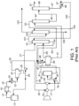
- FIG. 1 Existing process for recovering gaseous products from the product mixture obtained by contacting a hydrocarbon feed with a catalyst in a fluid catalytic cracking process is shown in FIG. 1 .
- Gaseous mixture from top of main fractionator 12 is supplied to overhead cooler-condenser 16 via gas conduit 14.
- Gas-liquid fractions thus obtained are separated in overhead receiver drum separator 24.
- the separated liquid fraction referred to as unstabilized naphtha is supplied as lean oil to primary absorber 75 via liquid conduit 27.
- the gaseous fraction is supplied via conduit 26 to suction of the first stage compressor 76.
- the gas fraction from inter-stage drum 80 is supplied via conduit 81 to second stage compressor 84.
- the inter-stage liquid fraction from inter-stage drum 80 via conduit 82 is combined in conduit 85 with the gaseous fraction compressed in second stage 84.
- the combined stream in conduit 85 is further joined by rich oil stream liquid from primary absorber 75 via conduit 94 and the overhead gaseous fraction from stripper 92 via conduit 93.
- the resultant stream 87 after it is cooled in high pressure cooler 86 is separated into gas and liquid fractions in high pressure receiver separator 89.
- the liquid fraction obtained from separator 89 is fed via conduit 91 to a stripper 92 wherein components lighter than ethane are stripped off from the feed and are recycled back via conduit 93 to high pressure separator 89 .
- Bottoms of stripper 92 are fed via conduit 95 to a debutanizer column 96 where components lighter than butane present in the feed are separated as column overheads and are fed further to a propylene separation unit via conduit 97.
- Bottom of debutanizer 96 in conduit 97 after being cooled in exchanger 98 to 38°C to 40°C is split to gasoline recycle and supplied to primary absorber 75 via conduit 100.
- Gaseous fraction from the high pressure separator 89 comprising of lighters and C 3 -C 5 components, is fed via conduit 90 to the bottom of primary absorber 75 wherein C 3- C 5 components are absorbed by the down-flowing lean absorber oil.
- the gaseous fraction obtained from primary absorber 75 is fed via conduit 101 to sponge absorber 102.
- the resulted gas fraction in conduit 103 from sponge absorber 102 contains light gases of C 2 and lighter and some losses of C 3 .
- the absorbed hydrocarbons in sponge absorber 102 are recycled back to main fractionators via conduit 105.
- the existing process for recovering gaseous products from the product mixture obtained by contacting a hydrocarbon feed with a catalyst in a fluid catalytic cracking process uses unstabilized gasoline from main fractionator overhead receiver as lean oil to gas concentration primary absorber.
- unstabilized gasoline from main fractionator overhead receiver as lean oil to gas concentration primary absorber.
- This design not only improves the recovery of propylene, but it is more economical to use a flash drum as opposed to other traditional methods used in gas concentration units and mainly gasoline recycle from the debutanizer which increases equipment sizes and utilities.
- This design will increase the load on the wet gas compressor by 2% to 5% but it is much more economical than increasing the gasoline recycle in gas concentration unit. For new units design the increase in propylene recovery becomes uneconomical using traditional methods at certain level.
- propylene recovery can be increased by nearly 1% without modifications for existing equipment.
- the extra load on the existing wet compressor of 2% to 5% can be accommodated by slightly changing the suction operating pressure if the compressor is near its maximum limit.
- the new equipment can be designed and installed in typical turnaround or in some cases may be while the unit is in operation.
- stripper, debutanizer, stripper reboiler, debtitanizer reboiler and debutanizer overhead condenser it will be possible to reduce the gasoline recycle and maintain same C 3 recovery. This will allow more feed to the gas concentration unit or more propylene production at FCC reactor.
- a process 100 for the recovery of propylene is depicted.
- a gaseous mixture in conduit 14 from the top of main fractionator 12 is supplied to an overhead air cooler 16 and is then supplied to a cooler-condenser 20 via gas/liquid conduit 18.
- Gas-liquid fractions thus obtained are separated in a overhead receiver 24.
- the separated liquid fraction unstabilized gasoline leaves the receiver 24 via liquid conduit 28 while the gas leaves the receiver via conduit 26 to wet gas compressor.
- the unstabilized gasoline via conduit 28 is split and a portion of the liquid fraction in conduit 29 is sent back to the main fractionator 12.
- the net unstabilized gasoline liquid fraction in conduit 27 is then heated via feed/bottoms exchanger 30.
- the resultant stream in conduit 38 obtained from heat exchanger 30 is fed to heat exchanger 40 for further heating by a stream in conduit 42.
- the stream of conduit 42 can either be a process stream or LP steam.
- Liquid gas mixture from heat exchanger 40 is fed via conduit 44 to a flash drum 46.
- the gaseous fraction in conduit 48 obtained from flash drum 46 is supplied to conduit 26 before the wet gas compressor.
- the flash drum vapor in conduit 48 contain light ends and nearly 70% of the propylene in the flash drum feed from conduit 44.
- the flash drum liquid in conduit 50 is pumped to feed/bottoms exchanger 30, cooled in a water cooler 34 to 35°C to 40°C and then routed to primary absorber. Therefore, the liquid to the primary absorber has less light material and propylene and therefore less loading on primary absorber which results in higher propylene recovery for the gas concentration unit.
- a process 200 for the recovery of propylene is depicted.
- a two stage flash for unstabilized gasoline is used before routing to gas concentration unit primary absorber.
- a gaseous mixture in conduit 14 from the top of main fractionator 12 is supplied to an overhead air cooler 16 and is then supplied to a cooler-condenser 20 via gas/liquid conduit 18.
- Gas-liquid fractions thus obtained are separated in a overhead receiver 24.
- the separated liquid fraction unstabilized gasoline leaves the receiver 24 via liquid conduit 28 while the gas leaves the receiver via conduit 26 to wet gas compressor.
- the unstabilized gasoline via conduit 28 is split and a portion of the liquid fraction in conduit 29 is sent back to the main fractionator 12.
- the net unstabilized gasoline liquid fraction in conduit 27 is then heated via feed/bottoms exchanger 30.
- the resultant stream in conduit 38 obtained from heat exchanger 30 is fed to a split shell flash drum 60.
- the flash drum illustrated in FIG. 2 comprises a split shell flash drum having a first side 70 and a second side 72 wherein the first side 70 and the second side 72 are completely separated by a vertical wall and the contents of the first side and the second side do not come in contact with each other.
- the gaseous fraction in conduit 48 obtained from flash drum 60 and side 70 is supplied to conduit 26 before the wet gas compressor.
- the first bottom stream 44 from the first side 70 of the split shell flash drum 60 is pumped via conduit 44 to heat exchanger 40 for further heating by a stream in conduit 42.
- the stream of conduit 42 can either be a process stream or LP steam.
- the resultant stream from exchanger 40 leaves via conduit 51 and send to the second side 72 of the split shell flash drum 60.
- the second overhead stream 58 from the second side 72 of the split shell flash drum 60 is supplied to conduit 26 before the wet gas compressor.
- the second bottoms stream 50 from the second side 72 of the split shell flash drum 60 is pumped to feed/bottoms exchanger 30, cooled in a water cooler 34 to 35°C to 40°C and then routed to primary absorber. Therefore, the liquid to the primary absorber has less light material and propylene and therefore less loading on primary absorber which results in higher propylene recovery for the gas concentration unit.
- split shell design can be used for the flash drum as illustrated in figure 2 .
- the benefit is a reduction of the vapor to wet gas compressor while maintaining same recovery in gas concentration unit.
- the amount of propylene removed from the unstabilized gasoline is the same as with a single flash drum but amount of vapor going to wet gas compressor will be less as shown in Table 2 below.
- the flow to wet gas compressor will be reduced when using a split shell or dividing wall drum for nearly the same amount of propylene removal from unstabilized gasoline.
- the total flow going to wet gas compressor will be slightly at a lower temperature.
Landscapes
- Chemical & Material Sciences (AREA)
- Oil, Petroleum & Natural Gas (AREA)
- Chemical Kinetics & Catalysis (AREA)
- Engineering & Computer Science (AREA)
- General Chemical & Material Sciences (AREA)
- Organic Chemistry (AREA)
- Analytical Chemistry (AREA)
- Production Of Liquid Hydrocarbon Mixture For Refining Petroleum (AREA)
Description
- This application claims priority to
U.S. Application No. 62/268,041 which was filed December 16, 2015 - The present invention relates to processes for propylene recovery. More specifically, the present invention relates to processes for enhanced recovery of propylene and liquid petroleum gas (LPG) from the fuel gas produced in fluid catalytic cracking (FCC) units by minimizing the light ends and propylene in the unstabilized gasoline which is used as lean oil for the primary absorber of the FCC gas concentration unit.
- In FCC units, most of the propylene leaves the FCC factionator overhead receiver in the vapor phase, from which it is recovered in downstream FCC gas concentration facilities. By virtue of the mixing which takes place between liquid and vapor phases in conventional overhead condensing and receiving steps, the liquid phase leaving the receiver carries with it a considerable amount of propylene and light ends. The liquid is the unstabilized gasoline which is used as the lean oil for the primary absorber of FCC gas concentration unit. The presence of light ends and propylene in the unstabilized gasoline increases the load on the primary absorber and this will result in losses of propylene to fuel gas and less propylene recovery. Increased loss is experienced when the unit operating pressures at main column receiver are increased in view of the fact that the liquid-vapor equilibrium at higher pressures favors more propylene in the liquid phase. The same concept for minimizing propylene in unstabilized gasoline before routing to primary absorber was discovered by UOP and discussed in patent number
US 3,893,905 . - The equipment requirements discussed in patent number
US 3,893,905 is a modification in the design of FCC fractionator overhead receiver condensers. This produce complexity in the design and not possible for existing FCC units. The present invention uses a simpler equipment design which can be used for existing FCC units. - In the traditional process, the product mixture from FCC main column overhead comprising gasoline, LPG, and fuel gas are first condensed and gravity separated to produce unstabilized gasoline, which is subsequently used in the primary absorber to absorb propylene and LPG from fuel gas. However, high recoveries of propylene become more difficult or uneconomical using traditional processes for recovery due to the presence of light ends and propylene in the unstabilized gasoline. Propylene in unstabilized gasoline can range from 2 mol% to 5 mol% or above.
-
US 5360533 A ,US 2009/112029 A1 ,EP 0509592 A1 ,CN 104650962A andUS 2011/108457 A1 describe processes for the recovery of light ends and propylene downstream of a FCC unit. - The present invention reduces the amount of propylene and LPG lost in FCC units operating either at lower or higher pressures. In the embodiments of this invention a primary absorber feed flash drum decreases the propylene and light ends in unstabilized gasoline and when it is routed to the primary absorber more propylene and LPG are recovered.
- Accordingly the invention as defined in claim 1 relates to a process for the recovery of propylene comprising (i) contacting a hydrocarbon feed with a catalyst in a fluid catalytic cracking process to produce a product stream; (ii) distilling the product stream in a fractionator to obtain heavier liquid products as side/bottom draws and a gaseous top product; (iii) cooling and condensing the gaseous top product and thereafter, separating the obtained gas-liquid mixture in a receiver to obtain an unstabilized gasoline liquid fraction and a lighter gaseous fraction; (iv) sequentially sending the gaseous fraction obtained from step (iii) to a wet gas compressor train; (v) feeding a first portion of the liquid fraction obtained in step (iii) back to the fractionator; (vi) feeding a second portion of the liquid fraction obtained in step (iii) to at least one heat exchanger to produce a heated stream; (vii) feeding the heated stream to a flash drum to produce a flashed light ends stream and a bottoms liquid stream, wherein the flashed light ends stream contains light ends and propylene; (viii) sending the flashed light ends stream to the wet gas compressor train in step (iv) and (ix) sending the bottoms liquid stream to one or more heat exchangers in step (vi), and then routing the liquid stream to a FCC gas concentration absorber.
- In an embodiment, the one or more heat exchangers heats the second portion of the liquid fraction from 38°C to 80°C. In a further embodiment the flashed light ends stream contains nearly 70% of the propylene in the flash drum feed. In another embodiment the one or more of the heat exchanges uses a waste heat process stream. In an embodiment, two heat exchangers are used to heat the second portion of the liquid fraction.
- According to an additional embodiment of the invention, the flash drum can be a split shell flash drum and hence steps (viii) and (ix) are carried out by feeding the heated stream to a split shell flash drum having a first side and a second side wherein the heated stream is sent to the first side of the split shell to produce a first flashed light ends stream to be sent back to the wet gas compressor in step (iv) and a first bottoms stream wherein the bottoms stream is heated and sent to the second side of the split shell flash drum to produce a second flashed light ends stream to be sent back to the wet gas compressor in step (iv) and a second bottoms stream wherein the second bottoms stream is sent to one or more heat exchangers in step (vi) before routing liquid stream to FCC gas concentration absorber.
- Additional objects, advantages and novel features of the examples will be set forth in part in the description which follows, and in part will become apparent to those skilled in the art upon examination of the following description and the accompanying drawings or may be learned by production or operation of the examples. The objects and advantages of the concepts may be realized and attained by means of the methodologies, instrumentalities and combinations particularly pointed out in the appended claims.
- As used herein, the term "stream", "feed", "product", "part" or "portion" can include various hydrocarbon molecules, such as straight-chain, branched, or cyclic alkanes, alkenes, alkadienes, and alkynes, and optionally other substances, such as gases, e.g., hydrogen, or impurities, such as heavy metals, and sulfur and nitrogen compounds. The stream can also include aromatic and non-aromatic hydrocarbons. Moreover, the hydrocarbon molecules may be abbreviated C1, C2, C3, Cn where "n" represents the number of carbon atoms in the one or more hydrocarbon molecules or the abbreviation may be used as an adjective for, e.g., non-aromatics or compounds. Similarly, aromatic compounds may be abbreviated A6. A7, As, An where "n" represents the number of carbon atoms in the one or more aromatic molecules. Furthermore, a superscript "+" or "-" may be used with an abbreviated one or more hydrocarbons notation, e.g., C3+ or C3-, which is inclusive of the abbreviated one or more hydrocarbons. As an example, the abbreviation "C3+" means one or more hydrocarbon molecules of three or more carbon atoms.
- As used herein, the term "zone" can refer to an area including one or more equipment items and/or one or more sub-zones. Equipment items can include, but are not limited to, one or more reactors or reactor vessels, separation vessels, distillation towers, heaters, exchangers, tubes, pumps, compressors, and controllers. Additionally, an equipment item, such as a reactor, dryer, or vessel, can further include one or more zones or sub-zones.
- The term "column" means a distillation column or columns for separating one or more components of different volatilities. Unless otherwise indicated, each column includes a condenser on an overhead of the column to condense and reflux a portion of an overhead stream back to the top of the column and a reboiler at a bottom of the column to vaporize and send a portion of a bottoms stream back to the bottom of the column. Feeds to the columns may be preheated. The top pressure is the pressure of the overhead vapor at the vapor outlet of the column. The bottom temperature is the liquid bottom outlet temperature. Overhead lines and bottoms lines refer to the net lines from the column downstream of any reflux or reboil to the column. Stripping columns omit a reboiler at a bottom of the column and instead provide heating requirements and separation impetus from a fluidized inert media such as steam.
- As used herein, the term "separator" means a vessel which has an inlet and at least an overhead vapor outlet and a bottoms liquid outlet and may also have an aqueous stream outlet from a boot. A flash drum is a type of separator which may be in downstream communication with a separator that may be operated at higher pressure.
- The drawing figures depict one or more implementations in accord with the present concepts, by way of example only, not by way of limitations. In the figures, like reference numerals refer to the same or similar elements.
-
FIG. 1 illustrates the prior art process. -
FIG. 2 is an illustration of the overall flow scheme of the system for improving propylene recovery from FCC gas using a flash drum for unstabilized gasoline before routing it to the primary absorber of gas concentration unit. -
FIG. 3 is an illustration of the overall flow scheme of the system for improving propylene recovery from FCC gas using a split shell flash drum for unstabilized gasoline before routing it to the primary absorber of gas concentration unit. - The following detailed description is merely exemplary in nature and is not intended to limit the invention and uses of the embodiment described. Furthermore, there is no intention to be bound by any theory presented in the preceding background or the following detailed description.
- Those skilled in the art will recognize that the process flow diagram of
FIG. 1 has been simplified by the elimination of many pieces of process equipment including for example, heat exchangers, process control systems, pumps, fractionation column overhead, reboiler systems and reactor internals, etc. which are not necessary to an understanding of the process. It may also be readily discerned that the process flow presented in the drawing may be modified in many aspects without departing from the basic overall concept. For example, the depiction of required heat exchangers in the drawing has been held to a minimum for purposes of simplicity. Those skilled in the art will recognize that the choice of heat exchange methods employed to obtain the necessary heating and cooling at various points within the process is subject to a large amount of variation as to how it is performed. In a process as complex as this, there exists many possibilities for indirect heat exchange between different process streams. Depending on the specific location and circumstance of the installation of the subject process, it may also be desired to employ heat exchange against steam, hot oil, or process streams from other processing units not shown on the drawing. - Existing process for recovering gaseous products from the product mixture obtained by contacting a hydrocarbon feed with a catalyst in a fluid catalytic cracking process is shown in
FIG. 1 . Gaseous mixture from top ofmain fractionator 12 is supplied to overhead cooler-condenser 16 viagas conduit 14. Gas-liquid fractions thus obtained are separated in overheadreceiver drum separator 24. The separated liquid fraction referred to as unstabilized naphtha is supplied as lean oil toprimary absorber 75 vialiquid conduit 27. The gaseous fraction is supplied viaconduit 26 to suction of thefirst stage compressor 76. The discharge stream viaconduit 77 after getting cooled in inter-stage cooler 78 being separated into gas and liquid fractions ininter-stage drum 80. The gas fraction frominter-stage drum 80 is supplied viaconduit 81 tosecond stage compressor 84. The inter-stage liquid fraction frominter-stage drum 80 viaconduit 82 is combined inconduit 85 with the gaseous fraction compressed insecond stage 84. The combined stream inconduit 85 is further joined by rich oil stream liquid fromprimary absorber 75 viaconduit 94 and the overhead gaseous fraction fromstripper 92 viaconduit 93. Theresultant stream 87 after it is cooled in high pressure cooler 86 is separated into gas and liquid fractions in highpressure receiver separator 89. - The liquid fraction obtained from
separator 89 is fed viaconduit 91 to astripper 92 wherein components lighter than ethane are stripped off from the feed and are recycled back viaconduit 93 tohigh pressure separator 89 . Bottoms ofstripper 92 are fed viaconduit 95 to adebutanizer column 96 where components lighter than butane present in the feed are separated as column overheads and are fed further to a propylene separation unit viaconduit 97. Bottom ofdebutanizer 96 inconduit 97 after being cooled inexchanger 98 to 38°C to 40°C is split to gasoline recycle and supplied toprimary absorber 75 viaconduit 100. - Gaseous fraction from the
high pressure separator 89, comprising of lighters and C3-C5 components, is fed viaconduit 90 to the bottom ofprimary absorber 75 wherein C3-C5 components are absorbed by the down-flowing lean absorber oil. The gaseous fraction obtained fromprimary absorber 75 is fed viaconduit 101 tosponge absorber 102. Using light cycle oil as lean oil viaconduit 104 insponge absorber 102, the resulted gas fraction inconduit 103 fromsponge absorber 102 contains light gases of C2 and lighter and some losses of C3. The absorbed hydrocarbons insponge absorber 102 are recycled back to main fractionators viaconduit 105. - As explained above, the existing process for recovering gaseous products from the product mixture obtained by contacting a hydrocarbon feed with a catalyst in a fluid catalytic cracking process uses unstabilized gasoline from main fractionator overhead receiver as lean oil to gas concentration primary absorber. However, by heating up the unstabilized gasoline and flashing the lighter ends and the propylene before routing to primary absorber will increase the total propylene recovery in the gas concentration unit. This design not only improves the recovery of propylene, but it is more economical to use a flash drum as opposed to other traditional methods used in gas concentration units and mainly gasoline recycle from the debutanizer which increases equipment sizes and utilities. This design will increase the load on the wet gas compressor by 2% to 5% but it is much more economical than increasing the gasoline recycle in gas concentration unit. For new units design the increase in propylene recovery becomes uneconomical using traditional methods at certain level.
- For existing units the investment to increase propylene recovery will be too large and requires many equipment modifications. With this invention and for new units design propylene recovery near 99.6% are economically possible. For existing units, propylene recovery can be increased by nearly 1% without modifications for existing equipment. The extra load on the existing wet compressor of 2% to 5% can be accommodated by slightly changing the suction operating pressure if the compressor is near its maximum limit. For existing FCC units, the new equipment can be designed and installed in typical turnaround or in some cases may be while the unit is in operation. In addition for existing units with equipment limitations of stripper, debutanizer, stripper reboiler, debtitanizer reboiler and debutanizer overhead condenser, it will be possible to reduce the gasoline recycle and maintain same C3 recovery. This will allow more feed to the gas concentration unit or more propylene production at FCC reactor.
- As illustrated in the preferred embodiment in
FIG. 2 , aprocess 100 for the recovery of propylene is depicted. In this embodiment, a gaseous mixture inconduit 14 from the top ofmain fractionator 12 is supplied to anoverhead air cooler 16 and is then supplied to a cooler-condenser 20 via gas/liquid conduit 18. Gas-liquid fractions thus obtained are separated in aoverhead receiver 24. The separated liquid fraction unstabilized gasoline leaves thereceiver 24 vialiquid conduit 28 while the gas leaves the receiver viaconduit 26 to wet gas compressor. The unstabilized gasoline viaconduit 28 is split and a portion of the liquid fraction inconduit 29 is sent back to themain fractionator 12. The net unstabilized gasoline liquid fraction inconduit 27 is then heated via feed/bottoms exchanger 30. The resultant stream inconduit 38 obtained fromheat exchanger 30 is fed toheat exchanger 40 for further heating by a stream inconduit 42. The stream ofconduit 42 can either be a process stream or LP steam. Liquid gas mixture fromheat exchanger 40 is fed viaconduit 44 to aflash drum 46. - The gaseous fraction in
conduit 48 obtained fromflash drum 46 is supplied toconduit 26 before the wet gas compressor. The flash drum vapor inconduit 48 contain light ends and nearly 70% of the propylene in the flash drum feed fromconduit 44. The flash drum liquid inconduit 50 is pumped to feed/bottoms exchanger 30, cooled in awater cooler 34 to 35°C to 40°C and then routed to primary absorber. Therefore, the liquid to the primary absorber has less light material and propylene and therefore less loading on primary absorber which results in higher propylene recovery for the gas concentration unit. - As illustrated in another preferred embodiment in
FIG. 3 , aprocess 200 for the recovery of propylene is depicted. In this process a two stage flash for unstabilized gasoline is used before routing to gas concentration unit primary absorber. In this embodiment, a gaseous mixture inconduit 14 from the top ofmain fractionator 12 is supplied to anoverhead air cooler 16 and is then supplied to a cooler-condenser 20 via gas/liquid conduit 18. Gas-liquid fractions thus obtained are separated in aoverhead receiver 24. The separated liquid fraction unstabilized gasoline leaves thereceiver 24 vialiquid conduit 28 while the gas leaves the receiver viaconduit 26 to wet gas compressor. The unstabilized gasoline viaconduit 28 is split and a portion of the liquid fraction inconduit 29 is sent back to themain fractionator 12. The net unstabilized gasoline liquid fraction inconduit 27 is then heated via feed/bottoms exchanger 30. The resultant stream inconduit 38 obtained fromheat exchanger 30 is fed to a splitshell flash drum 60. The flash drum illustrated inFIG. 2 comprises a split shell flash drum having afirst side 70 and asecond side 72 wherein thefirst side 70 and thesecond side 72 are completely separated by a vertical wall and the contents of the first side and the second side do not come in contact with each other. The gaseous fraction inconduit 48 obtained fromflash drum 60 andside 70 is supplied toconduit 26 before the wet gas compressor. - The
first bottom stream 44 from thefirst side 70 of the splitshell flash drum 60 is pumped viaconduit 44 toheat exchanger 40 for further heating by a stream inconduit 42. The stream ofconduit 42 can either be a process stream or LP steam. The resultant stream fromexchanger 40 leaves viaconduit 51 and send to thesecond side 72 of the splitshell flash drum 60. The secondoverhead stream 58 from thesecond side 72 of the splitshell flash drum 60 is supplied toconduit 26 before the wet gas compressor. The second bottoms stream 50 from thesecond side 72 of the splitshell flash drum 60 is pumped to feed/bottoms exchanger 30, cooled in awater cooler 34 to 35°C to 40°C and then routed to primary absorber. Therefore, the liquid to the primary absorber has less light material and propylene and therefore less loading on primary absorber which results in higher propylene recovery for the gas concentration unit. - The following examples are intended to further illustrate the subject embodiments. These illustrations of different embodiments are not meant to limit the claims to the particular details of these examples.
- An FCC unit was designed as per the prior art flow scheme. It was possible to achieve propylene recovery of 98.93 mol%. Any additional propylene recovery using traditional methods was not possible and was not economical. By adding the new invention to the design of the unit, it was possible to achieve higher recovery which resulted in higher revenue and payback of a few months based on new equipment cost. A comparison of base case vs. the case with the additional of new equipments is shown in Table 1.
TABLE 1 Base Case New case: Base Case with the addition of new equipment Delta New vs. Base Propylene Recovery,°% 98.93 99.61 0.68 Propylene Recovered, Metric T/year 735848.1 740848.3 5000.2 Propane Recovered, Metric T/year 118510.8 119091.5 580.7 Value of delta Propylene & propane recovered, MM$/year 5.86 Loss of value of Propylene & propane in Fuel Gas MM$/year -1.21 Operating Cost using LP steam, MM$/year -1.5 Net Revenue, MM$/year 3.15 Equipment Cost, MM$ 0.86 Payback based on equipment cost, Months 3 to 4 - As shown in the above Table 1, with new invention it was possible to achieve higher propylene recovery and the payback for the new equipment investment is expected to be a few months. In addition, the above analysis was done for the worst case scenario using LP steam for heating the unstabilized gasoline. In most cases it will be possible to heat up the unstabilized gasoline with a waste heat process stream available in the gas recovery or FCC main fractionation section. This will increase the yearly revenue from MM$3.15 to MM$4.65
- Another analysis we performed is the affect of the new invention on gasoline recycle.
- For same propylene as the base case of example 1 and with the addition of flash drum, it was possible to reduce gasoline recycle from the debutanizer to absorber by 50%. This has a big saving in equipment sizes and utilities on the gas concentration equipment like primary absorber, stripper, debutanizer, stripper reboiler, debutanizer reboiler/overhead condenser and gas concentration unit water coolers.
- For existing units and if it is desired to reduce the load on wet gas compressor due to capacity limitations, split shell design can be used for the flash drum as illustrated in
figure 2 . The benefit is a reduction of the vapor to wet gas compressor while maintaining same recovery in gas concentration unit. The amount of propylene removed from the unstabilized gasoline is the same as with a single flash drum but amount of vapor going to wet gas compressor will be less as shown in Table 2 below.TABLE 2 Unstabilized gasoline flow, kg/h: 257,508 Flash Drum Vapor without Dividing Wall Flash Drum Dividing Wall Vapor from 1st Compartment Flash Drum Dividing Wall Vapor from 2nd Compartment Flash Drum Dividing wall Total vapor from 1st & 2nd Compartments Vapor Flow, kg/h 25671 3925 18404 22329 Vapor Flow as % of Wet Gas Compressor Normal flow 4.77 0.73 3.42 4.15 Temperature, ° C 79 60 79 76 Propylene In vapor, kg/h 1794 567 1234 1801 Wet Gas Compressor suction temperature(normal flow+flash drum vapor), °C 39.7 39.3 - As shown in the above table, the flow to wet gas compressor will be reduced when using a split shell or dividing wall drum for nearly the same amount of propylene removal from unstabilized gasoline. In addition the total flow going to wet gas compressor will be slightly at a lower temperature.
- It should be noted that various changes and modifications to the presently preferred embodiments described herein will be apparent to those skilled in the art. Such changes and modifications may be made without departing from the scope of the present invention as defined in the appended claims and without diminishing its attendant advantages.
- Without further elaboration, it is believed that using the preceding description that one skilled in the art can utilize the present invention to its fullest extent and easily ascertain the essential characteristics of this invention, without departing from the scope thereof as definied in the appended claims.
- In the foregoing, all temperatures are set forth in degrees Celsius and, all parts and percentages are by weight, unless otherwise indicated.
Claims (5)
- A process for the recovery of propylene comprising:(i) contacting a hydrocarbon feed with a catalyst in a fluid catalytic cracking process to produce a product stream;(ii) distilling the product stream in a fractionator to obtain heavier liquid products as side/bottom draws and a gaseous top product;(iii) cooling and condensing the gaseous top product and thereafter, separating the obtained gas-liquid mixture in a receiver to obtain an unstabilized gasoline liquid fraction and a lighter gaseous fraction;(iv) sequentially sending the gaseous fraction obtained from step (iii) to a wet gas compressor train;(v) feeding a first portion of the liquid fraction obtained in step (iii) back to the fractionator;(vi) feeding a second portion of the liquid fraction obtained in step (iii) to at least one heat exchanger to produce a heated stream;(vii) feeding the heated stream to a flash drum to produce a flashed light ends stream and a bottoms liquid stream, wherein the flashed light ends stream contains light ends and propylene;(viii) sending the flashed light ends stream to the wet gas compressor train in step (iv), and(ix) sending the bottoms liquid stream to one or more heat exchangers in step (vi), and then routing the liquid stream to a FCC gas concentration absorber.
- The process of claim 1 wherein the one or more heat exchangers heats the second portion of the liquid fraction from 38°C to 80°C.
- The process of claim 1 wherein the flashed light ends stream contains nearly 70% of the propylene in the flash drum feed.
- The process of claim 1 wherein one or more of the heat exchanges uses a waste heat process stream.
- The process of claim 1 wherein two heat exchangers are used to heat the second portion of the liquid fraction.
Applications Claiming Priority (2)
| Application Number | Priority Date | Filing Date | Title |
|---|---|---|---|
| US201562268041P | 2015-12-16 | 2015-12-16 | |
| PCT/US2016/063923 WO2017105818A1 (en) | 2015-12-16 | 2016-11-29 | Process for improving propylene recovery from fcc recovery unit |
Publications (3)
| Publication Number | Publication Date |
|---|---|
| EP3390329A1 EP3390329A1 (en) | 2018-10-24 |
| EP3390329A4 EP3390329A4 (en) | 2019-08-21 |
| EP3390329B1 true EP3390329B1 (en) | 2023-09-20 |
Family
ID=59057374
Family Applications (1)
| Application Number | Title | Priority Date | Filing Date |
|---|---|---|---|
| EP16876356.3A Active EP3390329B1 (en) | 2015-12-16 | 2016-11-29 | Process for improving propylene recovery from fcc recovery unit |
Country Status (4)
| Country | Link |
|---|---|
| US (1) | US10487271B2 (en) |
| EP (1) | EP3390329B1 (en) |
| CN (1) | CN108473391B (en) |
| WO (1) | WO2017105818A1 (en) |
Families Citing this family (4)
| Publication number | Priority date | Publication date | Assignee | Title |
|---|---|---|---|---|
| US10471368B1 (en) * | 2018-06-29 | 2019-11-12 | Uop Llc | Process for separation of propylene from a liquefied petroleum gas stream |
| CN113350822B (en) * | 2021-06-09 | 2022-06-21 | 中山大学 | A fractionation device |
| CN115721951A (en) * | 2022-10-28 | 2023-03-03 | 新疆心连心能源化工有限公司 | Gasification tail gas treatment device and using method thereof |
| US12378172B2 (en) | 2022-11-16 | 2025-08-05 | Uop Llc | Process for recovering cracked product |
Family Cites Families (13)
| Publication number | Priority date | Publication date | Assignee | Title |
|---|---|---|---|---|
| US3122496A (en) * | 1960-08-26 | 1964-02-25 | Phillips Petroleum Co | Stripper-absorber method and apparatus |
| US3893905A (en) * | 1973-09-21 | 1975-07-08 | Universal Oil Prod Co | Fluid catalytic cracking process with improved propylene recovery |
| IT1247497B (en) * | 1991-04-18 | 1994-12-17 | Agip Petroli | PERFECTED PROCEDURE FOR THE RECOVERY OF HYDROCARBON FRACTIONS PRIMED BY LIGHT REFINERY PRODUCTS |
| US5360533A (en) * | 1993-06-08 | 1994-11-01 | Uop | Direct dry gas recovery from FCC reactor |
| US6271433B1 (en) * | 1999-02-22 | 2001-08-07 | Stone & Webster Engineering Corp. | Cat cracker gas plant process for increased olefins recovery |
| DE60123395T2 (en) * | 2000-03-03 | 2007-08-09 | Shell Internationale Research Maatschappij B.V. | USE OF LOW PRESSURE DISTILLATE AS ABSORBER OIL IN AN FCC RECOVERY SECTION |
| US7795486B2 (en) * | 2007-10-26 | 2010-09-14 | Uop Llc | Integrated production of FCC-produced C3 and cumene |
| EP2449059B1 (en) * | 2009-07-02 | 2020-05-27 | Reliance Industries Limited | An improved process for recovery of propylene and lpg from fcc fuel gas using stripped main column overhead distillate as absorber oil |
| CN102040445B (en) * | 2009-10-14 | 2013-10-23 | 卓润生 | A method for producing propylene from dehydrogenation of propane or propane-rich low-carbon hydrocarbons |
| US8414763B2 (en) * | 2009-11-09 | 2013-04-09 | Uop Llc | Process for recovering FCC product |
| CN102597179A (en) * | 2009-11-09 | 2012-07-18 | 环球油品公司 | Apparatus and process for recovering fcc product |
| US20130131417A1 (en) * | 2011-11-18 | 2013-05-23 | Uop Llc | Methods and systems for olefin production |
| CN104650962B (en) * | 2013-11-19 | 2017-02-15 | 中国石油天然气股份有限公司 | An improved catalytic cracking process |
-
2016
- 2016-11-29 WO PCT/US2016/063923 patent/WO2017105818A1/en not_active Ceased
- 2016-11-29 EP EP16876356.3A patent/EP3390329B1/en active Active
- 2016-11-29 CN CN201680073279.3A patent/CN108473391B/en active Active
-
2018
- 2018-05-31 US US15/994,906 patent/US10487271B2/en active Active
Also Published As
| Publication number | Publication date |
|---|---|
| US10487271B2 (en) | 2019-11-26 |
| US20180273853A1 (en) | 2018-09-27 |
| EP3390329A1 (en) | 2018-10-24 |
| EP3390329A4 (en) | 2019-08-21 |
| WO2017105818A1 (en) | 2017-06-22 |
| CN108473391B (en) | 2021-08-17 |
| CN108473391A (en) | 2018-08-31 |
Similar Documents
| Publication | Publication Date | Title |
|---|---|---|
| US7981256B2 (en) | Splitter with multi-stage heat pump compressor and inter-reboiler | |
| US10487271B2 (en) | Process for improving propylene recovery from FCC recovery unit | |
| US9127209B2 (en) | Process and apparatus for recovering hydroprocessed hydrocarbons with stripper columns | |
| EP3106504B1 (en) | Process for propylene and lpg recovery in fcc fuel gas | |
| US12570587B2 (en) | High temperature final dehydration reactor in dehydration process to prevent diethyl ether production | |
| US10287222B1 (en) | Process and apparatus for desorbent recovery | |
| CN106661459B (en) | Naphtha Isomerization Process Comprising Two Thermally Integrated Steps | |
| US20140262946A1 (en) | Process and apparatus for recovering hydroprocessed hydrocarbons with single product fractionation column | |
| RU2748268C1 (en) | Methods and apparatus for hydrocarbon isomerisation | |
| CN106350097A (en) | Process for the treatment of a hydrocarbon feed comprising hydrogen and c1 to c4 hydrocarbons | |
| CN106350107A (en) | Process for the treatment of a hydrocarbon feed containing hydrogen and hydrocarbons | |
| US20130192298A1 (en) | Distillation column heat pump with compressor inlet superheater | |
| US8911693B2 (en) | Process and apparatus for recovering hydroprocessed hydrocarbons with single product fractionation column | |
| US12516004B2 (en) | Processes and apparatuses for separating aromatic and non-aromatic hydrocarbons | |
| CN115066478B (en) | Site and cost-effective apparatus and method for separating one or more purified hydrocarbon streams from a crude hydrocarbon stream, such as for naphtha stabilization and LPG recovery | |
| CN106350113B (en) | Process for treating a hydrocarbon feed | |
| US20240279138A1 (en) | High temperature final dehydration reactor in dehydration process to prevent diethyl ether production | |
| US9816753B2 (en) | Methods and apparatuses for reforming of hydrocarbons including recovery of products using an absorption zone | |
| US9399743B2 (en) | Process for converting a hydrocarbon feed and apparatus relating thereto | |
| CN112823197A (en) | Process for fractionation of hydrocarbons |
Legal Events
| Date | Code | Title | Description |
|---|---|---|---|
| STAA | Information on the status of an ep patent application or granted ep patent |
Free format text: STATUS: THE INTERNATIONAL PUBLICATION HAS BEEN MADE |
|
| PUAI | Public reference made under article 153(3) epc to a published international application that has entered the european phase |
Free format text: ORIGINAL CODE: 0009012 |
|
| STAA | Information on the status of an ep patent application or granted ep patent |
Free format text: STATUS: REQUEST FOR EXAMINATION WAS MADE |
|
| 17P | Request for examination filed |
Effective date: 20180612 |
|
| AK | Designated contracting states |
Kind code of ref document: A1 Designated state(s): AL AT BE BG CH CY CZ DE DK EE ES FI FR GB GR HR HU IE IS IT LI LT LU LV MC MK MT NL NO PL PT RO RS SE SI SK SM TR |
|
| AX | Request for extension of the european patent |
Extension state: BA ME |
|
| DAV | Request for validation of the european patent (deleted) | ||
| DAX | Request for extension of the european patent (deleted) | ||
| A4 | Supplementary search report drawn up and despatched |
Effective date: 20190723 |
|
| RIC1 | Information provided on ipc code assigned before grant |
Ipc: C10G 11/18 20060101AFI20190717BHEP Ipc: B01D 53/00 20060101ALI20190717BHEP Ipc: B01D 1/20 20060101ALI20190717BHEP Ipc: C10G 70/04 20060101ALI20190717BHEP |
|
| REG | Reference to a national code |
Ref country code: DE Ref legal event code: R079 Free format text: PREVIOUS MAIN CLASS: C07C0007040000 Ipc: C10G0070040000 Ref country code: DE Ref legal event code: R079 Ref document number: 602016082942 Country of ref document: DE Free format text: PREVIOUS MAIN CLASS: C07C0007040000 Ipc: C10G0070040000 |
|
| GRAP | Despatch of communication of intention to grant a patent |
Free format text: ORIGINAL CODE: EPIDOSNIGR1 |
|
| STAA | Information on the status of an ep patent application or granted ep patent |
Free format text: STATUS: GRANT OF PATENT IS INTENDED |
|
| RIC1 | Information provided on ipc code assigned before grant |
Ipc: B01D 3/06 20060101ALI20230317BHEP Ipc: B01D 1/20 20060101ALI20230317BHEP Ipc: B01D 53/00 20060101ALI20230317BHEP Ipc: C10G 11/18 20060101ALI20230317BHEP Ipc: C10G 70/04 20060101AFI20230317BHEP |
|
| INTG | Intention to grant announced |
Effective date: 20230420 |
|
| P01 | Opt-out of the competence of the unified patent court (upc) registered |
Effective date: 20230421 |
|
| GRAS | Grant fee paid |
Free format text: ORIGINAL CODE: EPIDOSNIGR3 |
|
| GRAA | (expected) grant |
Free format text: ORIGINAL CODE: 0009210 |
|
| STAA | Information on the status of an ep patent application or granted ep patent |
Free format text: STATUS: THE PATENT HAS BEEN GRANTED |
|
| AK | Designated contracting states |
Kind code of ref document: B1 Designated state(s): AL AT BE BG CH CY CZ DE DK EE ES FI FR GB GR HR HU IE IS IT LI LT LU LV MC MK MT NL NO PL PT RO RS SE SI SK SM TR |
|
| REG | Reference to a national code |
Ref country code: GB Ref legal event code: FG4D |
|
| REG | Reference to a national code |
Ref country code: CH Ref legal event code: EP |
|
| REG | Reference to a national code |
Ref country code: IE Ref legal event code: FG4D |
|
| REG | Reference to a national code |
Ref country code: DE Ref legal event code: R096 Ref document number: 602016082942 Country of ref document: DE |
|
| REG | Reference to a national code |
Ref country code: LT Ref legal event code: MG9D |
|
| PG25 | Lapsed in a contracting state [announced via postgrant information from national office to epo] |
Ref country code: GR Free format text: LAPSE BECAUSE OF FAILURE TO SUBMIT A TRANSLATION OF THE DESCRIPTION OR TO PAY THE FEE WITHIN THE PRESCRIBED TIME-LIMIT Effective date: 20231221 |
|
| REG | Reference to a national code |
Ref country code: NL Ref legal event code: MP Effective date: 20230920 |
|
| PG25 | Lapsed in a contracting state [announced via postgrant information from national office to epo] |
Ref country code: SE Free format text: LAPSE BECAUSE OF FAILURE TO SUBMIT A TRANSLATION OF THE DESCRIPTION OR TO PAY THE FEE WITHIN THE PRESCRIBED TIME-LIMIT Effective date: 20230920 Ref country code: RS Free format text: LAPSE BECAUSE OF FAILURE TO SUBMIT A TRANSLATION OF THE DESCRIPTION OR TO PAY THE FEE WITHIN THE PRESCRIBED TIME-LIMIT Effective date: 20230920 Ref country code: NO Free format text: LAPSE BECAUSE OF FAILURE TO SUBMIT A TRANSLATION OF THE DESCRIPTION OR TO PAY THE FEE WITHIN THE PRESCRIBED TIME-LIMIT Effective date: 20231220 Ref country code: LV Free format text: LAPSE BECAUSE OF FAILURE TO SUBMIT A TRANSLATION OF THE DESCRIPTION OR TO PAY THE FEE WITHIN THE PRESCRIBED TIME-LIMIT Effective date: 20230920 Ref country code: LT Free format text: LAPSE BECAUSE OF FAILURE TO SUBMIT A TRANSLATION OF THE DESCRIPTION OR TO PAY THE FEE WITHIN THE PRESCRIBED TIME-LIMIT Effective date: 20230920 Ref country code: HR Free format text: LAPSE BECAUSE OF FAILURE TO SUBMIT A TRANSLATION OF THE DESCRIPTION OR TO PAY THE FEE WITHIN THE PRESCRIBED TIME-LIMIT Effective date: 20230920 Ref country code: GR Free format text: LAPSE BECAUSE OF FAILURE TO SUBMIT A TRANSLATION OF THE DESCRIPTION OR TO PAY THE FEE WITHIN THE PRESCRIBED TIME-LIMIT Effective date: 20231221 Ref country code: FI Free format text: LAPSE BECAUSE OF FAILURE TO SUBMIT A TRANSLATION OF THE DESCRIPTION OR TO PAY THE FEE WITHIN THE PRESCRIBED TIME-LIMIT Effective date: 20230920 |
|
| REG | Reference to a national code |
Ref country code: AT Ref legal event code: MK05 Ref document number: 1613419 Country of ref document: AT Kind code of ref document: T Effective date: 20230920 |
|
| PG25 | Lapsed in a contracting state [announced via postgrant information from national office to epo] |
Ref country code: NL Free format text: LAPSE BECAUSE OF FAILURE TO SUBMIT A TRANSLATION OF THE DESCRIPTION OR TO PAY THE FEE WITHIN THE PRESCRIBED TIME-LIMIT Effective date: 20230920 |
|
| PG25 | Lapsed in a contracting state [announced via postgrant information from national office to epo] |
Ref country code: IS Free format text: LAPSE BECAUSE OF FAILURE TO SUBMIT A TRANSLATION OF THE DESCRIPTION OR TO PAY THE FEE WITHIN THE PRESCRIBED TIME-LIMIT Effective date: 20240120 |
|
| PG25 | Lapsed in a contracting state [announced via postgrant information from national office to epo] |
Ref country code: AT Free format text: LAPSE BECAUSE OF FAILURE TO SUBMIT A TRANSLATION OF THE DESCRIPTION OR TO PAY THE FEE WITHIN THE PRESCRIBED TIME-LIMIT Effective date: 20230920 |
|
| PG25 | Lapsed in a contracting state [announced via postgrant information from national office to epo] |
Ref country code: ES Free format text: LAPSE BECAUSE OF FAILURE TO SUBMIT A TRANSLATION OF THE DESCRIPTION OR TO PAY THE FEE WITHIN THE PRESCRIBED TIME-LIMIT Effective date: 20230920 |
|
| PG25 | Lapsed in a contracting state [announced via postgrant information from national office to epo] |
Ref country code: SM Free format text: LAPSE BECAUSE OF FAILURE TO SUBMIT A TRANSLATION OF THE DESCRIPTION OR TO PAY THE FEE WITHIN THE PRESCRIBED TIME-LIMIT Effective date: 20230920 Ref country code: IS Free format text: LAPSE BECAUSE OF FAILURE TO SUBMIT A TRANSLATION OF THE DESCRIPTION OR TO PAY THE FEE WITHIN THE PRESCRIBED TIME-LIMIT Effective date: 20240120 Ref country code: ES Free format text: LAPSE BECAUSE OF FAILURE TO SUBMIT A TRANSLATION OF THE DESCRIPTION OR TO PAY THE FEE WITHIN THE PRESCRIBED TIME-LIMIT Effective date: 20230920 Ref country code: EE Free format text: LAPSE BECAUSE OF FAILURE TO SUBMIT A TRANSLATION OF THE DESCRIPTION OR TO PAY THE FEE WITHIN THE PRESCRIBED TIME-LIMIT Effective date: 20230920 Ref country code: CZ Free format text: LAPSE BECAUSE OF FAILURE TO SUBMIT A TRANSLATION OF THE DESCRIPTION OR TO PAY THE FEE WITHIN THE PRESCRIBED TIME-LIMIT Effective date: 20230920 Ref country code: AT Free format text: LAPSE BECAUSE OF FAILURE TO SUBMIT A TRANSLATION OF THE DESCRIPTION OR TO PAY THE FEE WITHIN THE PRESCRIBED TIME-LIMIT Effective date: 20230920 Ref country code: SK Free format text: LAPSE BECAUSE OF FAILURE TO SUBMIT A TRANSLATION OF THE DESCRIPTION OR TO PAY THE FEE WITHIN THE PRESCRIBED TIME-LIMIT Effective date: 20230920 Ref country code: PT Free format text: LAPSE BECAUSE OF FAILURE TO SUBMIT A TRANSLATION OF THE DESCRIPTION OR TO PAY THE FEE WITHIN THE PRESCRIBED TIME-LIMIT Effective date: 20240122 |
|
| PG25 | Lapsed in a contracting state [announced via postgrant information from national office to epo] |
Ref country code: PL Free format text: LAPSE BECAUSE OF FAILURE TO SUBMIT A TRANSLATION OF THE DESCRIPTION OR TO PAY THE FEE WITHIN THE PRESCRIBED TIME-LIMIT Effective date: 20230920 Ref country code: IT Free format text: LAPSE BECAUSE OF FAILURE TO SUBMIT A TRANSLATION OF THE DESCRIPTION OR TO PAY THE FEE WITHIN THE PRESCRIBED TIME-LIMIT Effective date: 20230920 |
|
| REG | Reference to a national code |
Ref country code: DE Ref legal event code: R097 Ref document number: 602016082942 Country of ref document: DE |
|
| REG | Reference to a national code |
Ref country code: CH Ref legal event code: PL |
|
| PG25 | Lapsed in a contracting state [announced via postgrant information from national office to epo] |
Ref country code: MC Free format text: LAPSE BECAUSE OF FAILURE TO SUBMIT A TRANSLATION OF THE DESCRIPTION OR TO PAY THE FEE WITHIN THE PRESCRIBED TIME-LIMIT Effective date: 20230920 |
|
| PG25 | Lapsed in a contracting state [announced via postgrant information from national office to epo] |
Ref country code: DK Free format text: LAPSE BECAUSE OF FAILURE TO SUBMIT A TRANSLATION OF THE DESCRIPTION OR TO PAY THE FEE WITHIN THE PRESCRIBED TIME-LIMIT Effective date: 20230920 |
|
| PG25 | Lapsed in a contracting state [announced via postgrant information from national office to epo] |
Ref country code: LU Free format text: LAPSE BECAUSE OF NON-PAYMENT OF DUE FEES Effective date: 20231129 |
|
| PG25 | Lapsed in a contracting state [announced via postgrant information from national office to epo] |
Ref country code: CH Free format text: LAPSE BECAUSE OF NON-PAYMENT OF DUE FEES Effective date: 20231130 |
|
| PLBE | No opposition filed within time limit |
Free format text: ORIGINAL CODE: 0009261 |
|
| STAA | Information on the status of an ep patent application or granted ep patent |
Free format text: STATUS: NO OPPOSITION FILED WITHIN TIME LIMIT |
|
| PG25 | Lapsed in a contracting state [announced via postgrant information from national office to epo] |
Ref country code: MC Free format text: LAPSE BECAUSE OF FAILURE TO SUBMIT A TRANSLATION OF THE DESCRIPTION OR TO PAY THE FEE WITHIN THE PRESCRIBED TIME-LIMIT Effective date: 20230920 Ref country code: LU Free format text: LAPSE BECAUSE OF NON-PAYMENT OF DUE FEES Effective date: 20231129 Ref country code: DK Free format text: LAPSE BECAUSE OF FAILURE TO SUBMIT A TRANSLATION OF THE DESCRIPTION OR TO PAY THE FEE WITHIN THE PRESCRIBED TIME-LIMIT Effective date: 20230920 Ref country code: CH Free format text: LAPSE BECAUSE OF NON-PAYMENT OF DUE FEES Effective date: 20231130 |
|
| REG | Reference to a national code |
Ref country code: BE Ref legal event code: MM Effective date: 20231130 |
|
| 26N | No opposition filed |
Effective date: 20240621 |
|
| GBPC | Gb: european patent ceased through non-payment of renewal fee |
Effective date: 20231220 |
|
| REG | Reference to a national code |
Ref country code: IE Ref legal event code: MM4A |
|
| PG25 | Lapsed in a contracting state [announced via postgrant information from national office to epo] |
Ref country code: IE Free format text: LAPSE BECAUSE OF NON-PAYMENT OF DUE FEES Effective date: 20231129 |
|
| PG25 | Lapsed in a contracting state [announced via postgrant information from national office to epo] |
Ref country code: GB Free format text: LAPSE BECAUSE OF NON-PAYMENT OF DUE FEES Effective date: 20231220 |
|
| PG25 | Lapsed in a contracting state [announced via postgrant information from national office to epo] |
Ref country code: BE Free format text: LAPSE BECAUSE OF NON-PAYMENT OF DUE FEES Effective date: 20231130 |
|
| PG25 | Lapsed in a contracting state [announced via postgrant information from national office to epo] |
Ref country code: FR Free format text: LAPSE BECAUSE OF NON-PAYMENT OF DUE FEES Effective date: 20231130 |
|
| PG25 | Lapsed in a contracting state [announced via postgrant information from national office to epo] |
Ref country code: SI Free format text: LAPSE BECAUSE OF FAILURE TO SUBMIT A TRANSLATION OF THE DESCRIPTION OR TO PAY THE FEE WITHIN THE PRESCRIBED TIME-LIMIT Effective date: 20230920 |
|
| PG25 | Lapsed in a contracting state [announced via postgrant information from national office to epo] |
Ref country code: SI Free format text: LAPSE BECAUSE OF FAILURE TO SUBMIT A TRANSLATION OF THE DESCRIPTION OR TO PAY THE FEE WITHIN THE PRESCRIBED TIME-LIMIT Effective date: 20230920 Ref country code: IE Free format text: LAPSE BECAUSE OF NON-PAYMENT OF DUE FEES Effective date: 20231129 Ref country code: GB Free format text: LAPSE BECAUSE OF NON-PAYMENT OF DUE FEES Effective date: 20231220 Ref country code: FR Free format text: LAPSE BECAUSE OF NON-PAYMENT OF DUE FEES Effective date: 20231130 Ref country code: BE Free format text: LAPSE BECAUSE OF NON-PAYMENT OF DUE FEES Effective date: 20231130 |
|
| PG25 | Lapsed in a contracting state [announced via postgrant information from national office to epo] |
Ref country code: BG Free format text: LAPSE BECAUSE OF FAILURE TO SUBMIT A TRANSLATION OF THE DESCRIPTION OR TO PAY THE FEE WITHIN THE PRESCRIBED TIME-LIMIT Effective date: 20230920 |
|
| PG25 | Lapsed in a contracting state [announced via postgrant information from national office to epo] |
Ref country code: BG Free format text: LAPSE BECAUSE OF FAILURE TO SUBMIT A TRANSLATION OF THE DESCRIPTION OR TO PAY THE FEE WITHIN THE PRESCRIBED TIME-LIMIT Effective date: 20230920 |
|
| PG25 | Lapsed in a contracting state [announced via postgrant information from national office to epo] |
Ref country code: CY Free format text: LAPSE BECAUSE OF FAILURE TO SUBMIT A TRANSLATION OF THE DESCRIPTION OR TO PAY THE FEE WITHIN THE PRESCRIBED TIME-LIMIT; INVALID AB INITIO Effective date: 20161129 |
|
| PG25 | Lapsed in a contracting state [announced via postgrant information from national office to epo] |
Ref country code: HU Free format text: LAPSE BECAUSE OF FAILURE TO SUBMIT A TRANSLATION OF THE DESCRIPTION OR TO PAY THE FEE WITHIN THE PRESCRIBED TIME-LIMIT; INVALID AB INITIO Effective date: 20161129 |
|
| PGFP | Annual fee paid to national office [announced via postgrant information from national office to epo] |
Ref country code: DE Payment date: 20251126 Year of fee payment: 10 |
|
| PGFP | Annual fee paid to national office [announced via postgrant information from national office to epo] |
Ref country code: TR Payment date: 20251117 Year of fee payment: 10 |
|
| PGFP | Annual fee paid to national office [announced via postgrant information from national office to epo] |
Ref country code: RO Payment date: 20251127 Year of fee payment: 10 |