EP3389112A1 - Battery module having improved frame structure and frame assembly therefor - Google Patents
Battery module having improved frame structure and frame assembly therefor Download PDFInfo
- Publication number
- EP3389112A1 EP3389112A1 EP17839863.2A EP17839863A EP3389112A1 EP 3389112 A1 EP3389112 A1 EP 3389112A1 EP 17839863 A EP17839863 A EP 17839863A EP 3389112 A1 EP3389112 A1 EP 3389112A1
- Authority
- EP
- European Patent Office
- Prior art keywords
- plate
- cell
- battery module
- frame assembly
- lower plate
- Prior art date
- Legal status (The legal status is an assumption and is not a legal conclusion. Google has not performed a legal analysis and makes no representation as to the accuracy of the status listed.)
- Granted
Links
Images


Classifications
-
- H—ELECTRICITY
- H01—ELECTRIC ELEMENTS
- H01M—PROCESSES OR MEANS, e.g. BATTERIES, FOR THE DIRECT CONVERSION OF CHEMICAL ENERGY INTO ELECTRICAL ENERGY
- H01M10/00—Secondary cells; Manufacture thereof
- H01M10/04—Construction or manufacture in general
- H01M10/0486—Frames for plates or membranes
-
- H—ELECTRICITY
- H01—ELECTRIC ELEMENTS
- H01M—PROCESSES OR MEANS, e.g. BATTERIES, FOR THE DIRECT CONVERSION OF CHEMICAL ENERGY INTO ELECTRICAL ENERGY
- H01M10/00—Secondary cells; Manufacture thereof
- H01M10/42—Methods or arrangements for servicing or maintenance of secondary cells or secondary half-cells
- H01M10/4207—Methods or arrangements for servicing or maintenance of secondary cells or secondary half-cells for several batteries or cells simultaneously or sequentially
-
- H—ELECTRICITY
- H01—ELECTRIC ELEMENTS
- H01M—PROCESSES OR MEANS, e.g. BATTERIES, FOR THE DIRECT CONVERSION OF CHEMICAL ENERGY INTO ELECTRICAL ENERGY
- H01M50/00—Constructional details or processes of manufacture of the non-active parts of electrochemical cells other than fuel cells, e.g. hybrid cells
- H01M50/10—Primary casings; Jackets or wrappings
- H01M50/102—Primary casings; Jackets or wrappings characterised by their shape or physical structure
- H01M50/105—Pouches or flexible bags
-
- H—ELECTRICITY
- H01—ELECTRIC ELEMENTS
- H01M—PROCESSES OR MEANS, e.g. BATTERIES, FOR THE DIRECT CONVERSION OF CHEMICAL ENERGY INTO ELECTRICAL ENERGY
- H01M50/00—Constructional details or processes of manufacture of the non-active parts of electrochemical cells other than fuel cells, e.g. hybrid cells
- H01M50/20—Mountings; Secondary casings or frames; Racks, modules or packs; Suspension devices; Shock absorbers; Transport or carrying devices; Holders
- H01M50/202—Casings or frames around the primary casing of a single cell or a single battery
-
- H—ELECTRICITY
- H01—ELECTRIC ELEMENTS
- H01M—PROCESSES OR MEANS, e.g. BATTERIES, FOR THE DIRECT CONVERSION OF CHEMICAL ENERGY INTO ELECTRICAL ENERGY
- H01M50/00—Constructional details or processes of manufacture of the non-active parts of electrochemical cells other than fuel cells, e.g. hybrid cells
- H01M50/20—Mountings; Secondary casings or frames; Racks, modules or packs; Suspension devices; Shock absorbers; Transport or carrying devices; Holders
- H01M50/204—Racks, modules or packs for multiple batteries or multiple cells
- H01M50/207—Racks, modules or packs for multiple batteries or multiple cells characterised by their shape
- H01M50/211—Racks, modules or packs for multiple batteries or multiple cells characterised by their shape adapted for pouch cells
-
- H—ELECTRICITY
- H01—ELECTRIC ELEMENTS
- H01M—PROCESSES OR MEANS, e.g. BATTERIES, FOR THE DIRECT CONVERSION OF CHEMICAL ENERGY INTO ELECTRICAL ENERGY
- H01M50/00—Constructional details or processes of manufacture of the non-active parts of electrochemical cells other than fuel cells, e.g. hybrid cells
- H01M50/20—Mountings; Secondary casings or frames; Racks, modules or packs; Suspension devices; Shock absorbers; Transport or carrying devices; Holders
- H01M50/218—Mountings; Secondary casings or frames; Racks, modules or packs; Suspension devices; Shock absorbers; Transport or carrying devices; Holders characterised by the material
- H01M50/22—Mountings; Secondary casings or frames; Racks, modules or packs; Suspension devices; Shock absorbers; Transport or carrying devices; Holders characterised by the material of the casings or racks
- H01M50/222—Inorganic material
- H01M50/224—Metals
-
- H—ELECTRICITY
- H01—ELECTRIC ELEMENTS
- H01M—PROCESSES OR MEANS, e.g. BATTERIES, FOR THE DIRECT CONVERSION OF CHEMICAL ENERGY INTO ELECTRICAL ENERGY
- H01M50/00—Constructional details or processes of manufacture of the non-active parts of electrochemical cells other than fuel cells, e.g. hybrid cells
- H01M50/20—Mountings; Secondary casings or frames; Racks, modules or packs; Suspension devices; Shock absorbers; Transport or carrying devices; Holders
- H01M50/262—Mountings; Secondary casings or frames; Racks, modules or packs; Suspension devices; Shock absorbers; Transport or carrying devices; Holders with fastening means, e.g. locks
- H01M50/264—Mountings; Secondary casings or frames; Racks, modules or packs; Suspension devices; Shock absorbers; Transport or carrying devices; Holders with fastening means, e.g. locks for cells or batteries, e.g. straps, tie rods or peripheral frames
-
- H—ELECTRICITY
- H01—ELECTRIC ELEMENTS
- H01M—PROCESSES OR MEANS, e.g. BATTERIES, FOR THE DIRECT CONVERSION OF CHEMICAL ENERGY INTO ELECTRICAL ENERGY
- H01M50/00—Constructional details or processes of manufacture of the non-active parts of electrochemical cells other than fuel cells, e.g. hybrid cells
- H01M50/50—Current conducting connections for cells or batteries
- H01M50/572—Means for preventing undesired use or discharge
-
- Y—GENERAL TAGGING OF NEW TECHNOLOGICAL DEVELOPMENTS; GENERAL TAGGING OF CROSS-SECTIONAL TECHNOLOGIES SPANNING OVER SEVERAL SECTIONS OF THE IPC; TECHNICAL SUBJECTS COVERED BY FORMER USPC CROSS-REFERENCE ART COLLECTIONS [XRACs] AND DIGESTS
- Y02—TECHNOLOGIES OR APPLICATIONS FOR MITIGATION OR ADAPTATION AGAINST CLIMATE CHANGE
- Y02E—REDUCTION OF GREENHOUSE GAS [GHG] EMISSIONS, RELATED TO ENERGY GENERATION, TRANSMISSION OR DISTRIBUTION
- Y02E60/00—Enabling technologies; Technologies with a potential or indirect contribution to GHG emissions mitigation
- Y02E60/10—Energy storage using batteries
-
- Y—GENERAL TAGGING OF NEW TECHNOLOGICAL DEVELOPMENTS; GENERAL TAGGING OF CROSS-SECTIONAL TECHNOLOGIES SPANNING OVER SEVERAL SECTIONS OF THE IPC; TECHNICAL SUBJECTS COVERED BY FORMER USPC CROSS-REFERENCE ART COLLECTIONS [XRACs] AND DIGESTS
- Y02—TECHNOLOGIES OR APPLICATIONS FOR MITIGATION OR ADAPTATION AGAINST CLIMATE CHANGE
- Y02P—CLIMATE CHANGE MITIGATION TECHNOLOGIES IN THE PRODUCTION OR PROCESSING OF GOODS
- Y02P70/00—Climate change mitigation technologies in the production process for final industrial or consumer products
- Y02P70/50—Manufacturing or production processes characterised by the final manufactured product
Definitions
- the present disclosure relates to a battery module, and more particularly, to a battery module having a structure in which a cell is supported by an outer frame, and a frame assembly therefor.
- battery modules are formed in a structure in which a plurality of cells are assembled by series and/or parallel connection.
- a battery module includes: a cell assembly in which a plurality of cells are arranged and stacked in one direction; and a frame having a plate capable of surrounding the cell assembly.
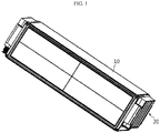
- a battery module of the related art is manufactured in a structure in which a cell assembly 20 is surrounded by a frame 10 formed in one piece by an extrusion or die casting method as shown in FIG. 1 .
- Korean Patent Application Publication No. 2015-0031861 discloses a battery module in which a side plate is placed adjacent to a side of a cell assembly.
- the battery module disclosed in Korean Patent Application Publication No. 2015-0031861 includes: a plurality of battery cells aligned in one direction; and a side plate placed adjacent to sides of the battery cells, wherein the side plate includes a pressing region protruding toward the battery cells to press the battery cells, and since the pressing region applies tension to the battery cells and prevents movement of the battery cells, the battery module is improved in safety.
- Korean Patent Application Publication No. 2012-0051237 discloses a battery module case in which at least two pouch-type secondary batteries are stacked and arranged side by side with electrode tap sides of the pouch-type secondary batteries being arranged in the same manner, wherein each of the pouch-type secondary batteries is mounted in a vertically or horizontally sliding manner, the battery module case is coupled to outer surfaces of the pouch-type secondary batteries including the electrode tap sides, and the battery module case has an upper, lower, and side separable assembly structure.
- the present disclosure is designed by taking problems as described above into consideration, and therefore the present disclosure is directed to providing a battery module having a structure in which a frame is formed by assembling plates made of a material such as a metal sheet, and to providing a frame assembly therefor.
- Another object of the present disclosure is to provide a battery module having a structure in which a frame is formed through a welding process, and to provide a frame assembly therefor.
- a battery module including: at least one cell; and a fame assembly including a lower plate configured to support a lower end surface of the cell, a side plate extending perpendicularly from any opposite edge ends of the lower plate and placed adjacent to an outermost side of the cell, and an upper plate coupled to an upper end of the side plate to cover an upper portion of the cell.
- an edge portion of the upper plate is coupled to the upper end of the side plate by welding.
- the battery module of the present disclosure may further include a first guide plate extending perpendicularly from other opposite edge ends of the lower plate to prevent separation of the cell.
- the first guide plate may be bent from the lower plate in one piece with the lower plate.
- the battery module of the present disclosure may further include a second guide plate extending perpendicularly from an edge end of the upper plate to prevent separation of the cell.
- the second guide plate may be bent from the upper plate in one piece with the upper plate.
- the side plate may be bent from the lower plate in one piece with the lower plate.
- a frame assembly of a battery module for supporting at least one cell from an outside of the battery module, the frame assembly including: a lower plate configured to support a lower end surface of the cell; a side plate perpendicularly extending from any opposite edge ends of the lower plate and placed adjacent to an outermost side of the cell; and an upper plate placed to cover an upper portion of the cell, opposite edge ends of the upper plate being coupled to an upper end of the side plate.
- the frame assembly of the battery module is made of a plate material such as a metal sheet for weight reduction and is assembled through a welding process for reducing process costs.
- the expansion of the side plate may be properly allowed, and thus the lifespan of the cell may not be negatively affected.
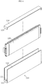
- FIG. 2 is an exploded perspective view illustrating a configuration of a battery module according to a preferred embodiment of the present disclosure.
- the battery module includes: a plurality of cells 100; and a frame assembly 110 arranged to surround the plurality of cells 100 and including a lower plate 111, a side plate 113, and an upper plate 114.
- Each of the cells 100 has a thin plate-like body, and is preferably a pouch-type secondary cell.
- the plurality of cells 100 are arranged in one direction to substantially form a stacked structure.
- the frame assembly 110 is a structure for accommodating, supporting, and protecting the cells 100 in units of a plurality of cells, and the frame assembly 110 includes the lower plate 111 placed below the cells 100, the side plate 113 placed adjacent to outermost sides of the cells 100, and the upper plate 114 placed above the cells 100.
- Each of the plates 111, 113, and 114 of the frame assembly 110 is formed of a metal sheet (or a metal plate) such as an aluminum plate having a thin thickness of about several millimeters.
- the lower plate 111 has a base surface capable of collectively supporting lower end surfaces of the plurality of cells 100.
- the side plate 113 extends perpendicularly upwards from any opposite edge ends of the lower plate 111 and are placed adjacent to the outermost sides of the cells 100. That is, a pair of side plates 113 are provided, and the interval between the side plates 113 is set to such an extent as to accommodate the plurality of cells 100.
- the side plates 113 are bent from the lower plate 111 in one piece with the lower plate 111 to form a ⁇ -shaped section.
- a first guide plate 112 extends perpendicularly upwards from other opposite edge ends of the lower plate 111 to a height of several centimeters so as to prevent separation of the cells 100 from the frame assembly 110 in forward and backward directions, that is, in directions perpendicular to the direction in which the cells 100 are arranged.
- the first guide plate 112 is bent from the lower plate 111 in one piece with the lower plate 111.
- the upper plate 114 is coupled to upper ends of the side plates 113 to collectively cover upper portions of the plurality of cells 100.
- opposite edge portions of the upper plate 114 are respectively welded to the upper ends of the side plates 113.
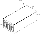
- weld zones (refer to W in FIG. 3 ) are formed on edge portions at which the side plates 113 meet the upper plate 114.
- a welding method such as a laser welding method, an ultrasonic welding method, or a spot welding method may be used.
- FIG. 3 illustrates a state in which the upper plate 114 is assembled to the upper ends of the side plates 113 by welding.
- the battery module including the frame assembly 110 provided in units of a plurality of cells 100 is manufactured by welding edge portions of the upper plate 114 to the upper ends of the side plates 113 in a state in which the plurality of cells 100 are arranged in the frame assembly 110.
- the width of the upper plate 114 is substantially the same as the interval between inner surfaces of the pair of side plates 113 or the interval between outer surfaces of the pair of side plates 113.
- a second guide plate 115 extends to a height of several centimeters, perpendicularly downwards from opposite edge ends of the upper plate 114 which are not in contact with the side plates 113, so as to prevent separation of the cells 100 from the frame assembly 110 in forward and backward directions, that is, in directions perpendicular to the direction in which the cells 100 are arranged.
- the second guide plate 115 is bent from the upper plate 114 in one piece with the upper plate 114.
- the battery module having a structure in which a frame assembly 110 is coupled on a single cell basis as shown in FIG. 4 .
- the battery module includes: a cell 100 disposed alone; and the frame assembly 110 provided to correspond to the single cell 100 and disposed to surround the cell 100, the frame assembly 110 including a lower plate 111, a side plate 113, and an upper plate 114.
- the frame assembly 110 is provided to correspond to each single cell 100, only one cell 100 is accommodated in the frame assembly 110, and thus the frame assembly 110 may have a slim shape.
- the lower plate 111, the side plate 113, and the upper plate 114 of the frame assembly 110 have the same specific configuration and coupling relationship as those described in the above embodiment, and thus detailed descriptions thereof will be omitted.
- the battery module including the frame assembly 110 provided on a cell basis is manufactured by welding an edge portion of the upper plate 114 to an upper end of the side plate 113 in a state in which the single cell 100 is placed in the frame assembly 110.
- weld zones W are formed on edge portions at which the side plate 113 meets the upper plate 114.
- the frame assembly 110 is assembled in units of a single cell 100 or a plurality of cells 100.
- the frame assembly 110 may be light because the lower plate 111, the side plate 113, and the upper plate 114 formed of a metal sheet (or a metal plate) such as an aluminum plate are organically coupled to each other.
- the lower plate 111 and the side plate 113 are formed in one piece through a bending process, and the upper plate 114 is coupled to the upper end of the side plate 113 by a welding process such as a laser welding process or an ultrasonic welding process.
- a battery module having a lower weight and incurring lower assembly costs compared to the case of using a frame manufactured by a convention extrusion or die casting method may be provided.
Landscapes
- Chemical & Material Sciences (AREA)
- Chemical Kinetics & Catalysis (AREA)
- Electrochemistry (AREA)
- General Chemical & Material Sciences (AREA)
- Engineering & Computer Science (AREA)
- Manufacturing & Machinery (AREA)
- Inorganic Chemistry (AREA)
- Battery Mounting, Suspending (AREA)
- Sealing Battery Cases Or Jackets (AREA)
Abstract
Description
- The present application claims priority to Korean Patent Application No.
10-2016-0103079 filed on August 12, 2016 - The present disclosure relates to a battery module, and more particularly, to a battery module having a structure in which a cell is supported by an outer frame, and a frame assembly therefor.
- In general, battery modules are formed in a structure in which a plurality of cells are assembled by series and/or parallel connection. Such a battery module includes: a cell assembly in which a plurality of cells are arranged and stacked in one direction; and a frame having a plate capable of surrounding the cell assembly.
- A battery module of the related art is manufactured in a structure in which a
cell assembly 20 is surrounded by aframe 10 formed in one piece by an extrusion or die casting method as shown inFIG. 1 . - However, such an extrusion or die casting method is a major cause of increasing the unit price of battery modules due to high process costs, and since the expansion of battery modules is forcibly inhibited, the lifespan of cells may be negatively affected.
- Alternatively, Korean Patent Application Publication No.
2015-0031861 2015-0031861 - Korean Patent Application Publication No.
2012-0051237 - Although techniques as described above have been proposed, technical means for stably supporting battery modules and reducing material or process costs while somewhat allowing the expansion of an end plate caused by swelling has not yet been proposed, and thus measures are needed.
- The present disclosure is designed by taking problems as described above into consideration, and therefore the present disclosure is directed to providing a battery module having a structure in which a frame is formed by assembling plates made of a material such as a metal sheet, and to providing a frame assembly therefor.
- Another object of the present disclosure is to provide a battery module having a structure in which a frame is formed through a welding process, and to provide a frame assembly therefor.
- To achieve the above-described objects, the present disclosure provides a battery module including: at least one cell; and a fame assembly including a lower plate configured to support a lower end surface of the cell, a side plate extending perpendicularly from any opposite edge ends of the lower plate and placed adjacent to an outermost side of the cell, and an upper plate coupled to an upper end of the side plate to cover an upper portion of the cell.
- Preferably, an edge portion of the upper plate is coupled to the upper end of the side plate by welding.
- The battery module of the present disclosure may further include a first guide plate extending perpendicularly from other opposite edge ends of the lower plate to prevent separation of the cell.
- The first guide plate may be bent from the lower plate in one piece with the lower plate.
- The battery module of the present disclosure may further include a second guide plate extending perpendicularly from an edge end of the upper plate to prevent separation of the cell.
- The second guide plate may be bent from the upper plate in one piece with the upper plate.
- The side plate may be bent from the lower plate in one piece with the lower plate.
- In another aspect of the present disclosure, there is provided a frame assembly of a battery module for supporting at least one cell from an outside of the battery module, the frame assembly including: a lower plate configured to support a lower end surface of the cell; a side plate perpendicularly extending from any opposite edge ends of the lower plate and placed adjacent to an outermost side of the cell; and an upper plate placed to cover an upper portion of the cell, opposite edge ends of the upper plate being coupled to an upper end of the side plate.
- According to the present disclosure, the frame assembly of the battery module is made of a plate material such as a metal sheet for weight reduction and is assembled through a welding process for reducing process costs.
- In addition, even when the battery module swells due to an overcharged cell, the expansion of the side plate may be properly allowed, and thus the lifespan of the cell may not be negatively affected.
- The accompanying drawings illustrate preferred embodiments of the present disclosure and together with the foregoing disclosure, serve to provide further understanding of the technical features of the present disclosure, and thus, the present disclosure is not construed as being limited to the drawings.
-
FIG. 1 is a perspective view illustrating an appearance of a battery module of the related art. -
FIG. 2 is an exploded perspective view illustrating a configuration of a battery module according to a preferred embodiment of the present disclosure. -
FIG. 3 is an assembled perspective view illustrating the battery module ofFIG. 2 . -
FIG. 4 is a perspective view illustrating a configuration of a battery module according to another embodiment of the present disclosure. -
FIG. 5 is an assembled perspective view illustrating the battery pack ofFIG. 4 . -
FIG. 2 is an exploded perspective view illustrating a configuration of a battery module according to a preferred embodiment of the present disclosure. - Referring to
FIG. 2 , according to the preferred embodiment of the present disclosure, the battery module includes: a plurality ofcells 100; and aframe assembly 110 arranged to surround the plurality ofcells 100 and including alower plate 111, aside plate 113, and anupper plate 114. - Each of the
cells 100 has a thin plate-like body, and is preferably a pouch-type secondary cell. The plurality ofcells 100 are arranged in one direction to substantially form a stacked structure. - The
frame assembly 110 is a structure for accommodating, supporting, and protecting thecells 100 in units of a plurality of cells, and theframe assembly 110 includes thelower plate 111 placed below thecells 100, theside plate 113 placed adjacent to outermost sides of thecells 100, and theupper plate 114 placed above thecells 100. Each of theplates frame assembly 110 is formed of a metal sheet (or a metal plate) such as an aluminum plate having a thin thickness of about several millimeters. - The
lower plate 111 has a base surface capable of collectively supporting lower end surfaces of the plurality ofcells 100. - The
side plate 113 extends perpendicularly upwards from any opposite edge ends of thelower plate 111 and are placed adjacent to the outermost sides of thecells 100. That is, a pair ofside plates 113 are provided, and the interval between theside plates 113 is set to such an extent as to accommodate the plurality ofcells 100. Preferably, theside plates 113 are bent from thelower plate 111 in one piece with thelower plate 111 to form a ⊏-shaped section. - A
first guide plate 112 extends perpendicularly upwards from other opposite edge ends of thelower plate 111 to a height of several centimeters so as to prevent separation of thecells 100 from theframe assembly 110 in forward and backward directions, that is, in directions perpendicular to the direction in which thecells 100 are arranged. Preferably, thefirst guide plate 112 is bent from thelower plate 111 in one piece with thelower plate 111. - The
upper plate 114 is coupled to upper ends of theside plates 113 to collectively cover upper portions of the plurality ofcells 100. Preferably, opposite edge portions of theupper plate 114 are respectively welded to the upper ends of theside plates 113. Thus, weld zones (refer to W inFIG. 3 ) are formed on edge portions at which theside plates 113 meet theupper plate 114. Here, a welding method such as a laser welding method, an ultrasonic welding method, or a spot welding method may be used. -
FIG. 3 illustrates a state in which theupper plate 114 is assembled to the upper ends of theside plates 113 by welding. As illustrated inFIG. 3 , the battery module including theframe assembly 110 provided in units of a plurality ofcells 100 is manufactured by welding edge portions of theupper plate 114 to the upper ends of theside plates 113 in a state in which the plurality ofcells 100 are arranged in theframe assembly 110. - Preferably, the width of the
upper plate 114 is substantially the same as the interval between inner surfaces of the pair ofside plates 113 or the interval between outer surfaces of the pair ofside plates 113. - A
second guide plate 115 extends to a height of several centimeters, perpendicularly downwards from opposite edge ends of theupper plate 114 which are not in contact with theside plates 113, so as to prevent separation of thecells 100 from theframe assembly 110 in forward and backward directions, that is, in directions perpendicular to the direction in which thecells 100 are arranged. Preferably, thesecond guide plate 115 is bent from theupper plate 114 in one piece with theupper plate 114. - Another embodiment of the present disclosure provides a battery module having a structure in which a
frame assembly 110 is coupled on a single cell basis as shown inFIG. 4 . In this case, the battery module includes: acell 100 disposed alone; and theframe assembly 110 provided to correspond to thesingle cell 100 and disposed to surround thecell 100, theframe assembly 110 including alower plate 111, aside plate 113, and anupper plate 114. - Since the
frame assembly 110 is provided to correspond to eachsingle cell 100, only onecell 100 is accommodated in theframe assembly 110, and thus theframe assembly 110 may have a slim shape. Thelower plate 111, theside plate 113, and theupper plate 114 of theframe assembly 110 have the same specific configuration and coupling relationship as those described in the above embodiment, and thus detailed descriptions thereof will be omitted. - As illustrated in
FIG. 5 , the battery module including theframe assembly 110 provided on a cell basis is manufactured by welding an edge portion of theupper plate 114 to an upper end of theside plate 113 in a state in which thesingle cell 100 is placed in theframe assembly 110. Thus, weld zones W are formed on edge portions at which theside plate 113 meets theupper plate 114. - In the battery module having the above-described configuration according to the preferred embodiment of the present disclosure, the
frame assembly 110 is assembled in units of asingle cell 100 or a plurality ofcells 100. - The
frame assembly 110 may be light because thelower plate 111, theside plate 113, and theupper plate 114 formed of a metal sheet (or a metal plate) such as an aluminum plate are organically coupled to each other. - When the
frame assembly 110 is manufactured, thelower plate 111 and theside plate 113 are formed in one piece through a bending process, and theupper plate 114 is coupled to the upper end of theside plate 113 by a welding process such as a laser welding process or an ultrasonic welding process. - According to the present disclosure, a battery module having a lower weight and incurring lower assembly costs compared to the case of using a frame manufactured by a convention extrusion or die casting method may be provided.
Claims (14)
- A battery module comprising:at least one cell; anda fame assembly comprising a lower plate configured to support a lower end surface of the cell, a side plate extending perpendicularly from any opposite edge ends of the lower plate and placed adjacent to an outermost side of the cell, and an upper plate coupled to an upper end of the side plate to cover an upper portion of the cell.
- The battery module of claim 1, wherein an edge portion of the upper plate is welded to the upper end of the side plate.
- The battery module of claim 1, further comprising a first guide plate extending perpendicularly from other opposite edge ends of the lower plate to prevent separation of the cell.
- The battery module of claim 3, wherein the first guide plate is bent from the lower plate in one piece with the lower plate.
- The battery module of claim 3, further comprising a second guide plate extending perpendicularly from an edge end of the upper plate to prevent separation of the cell.
- The battery module of claim 5, wherein the second guide plate is bent from the upper plate in one piece with the upper plate.
- The battery module of claim 1, wherein the side plate is bent from the lower plate in one piece with the lower plate.
- A frame assembly of a battery module for supporting at least one cell from an outside of the battery module, the frame assembly comprising:a lower plate configured to support a lower end surface of the cell;a side plate perpendicularly extending from any opposite edge ends of the lower plate and placed adjacent to an outermost side of the cell; andan upper plate placed to cover an upper portion of the cell, opposite edge ends of the upper plate being coupled to an upper end of the side plate.
- The frame assembly of claim 8, wherein the edge ends of the upper plate are welded to the upper end of the side plate.
- The frame assembly of claim 8, further comprising a first guide plate extending perpendicularly from other opposite edge ends of the lower plate to prevent separation of the cell.
- The frame assembly of claim 10, wherein the first guide plate is bent from the lower plate in one piece with the lower plate.
- The frame assembly of claim 11, further comprising a second guide plate extending perpendicularly from an edge end of the upper plate to prevent separation of the cell.
- The frame assembly of claim 12, wherein the second guide plate is bent from the upper plate in one piece with the upper plate.
- The frame assembly of claim 8, wherein the side plate is bent from the lower plate in one piece with the lower plate.
Applications Claiming Priority (2)
| Application Number | Priority Date | Filing Date | Title |
|---|---|---|---|
| KR1020160103079A KR102065098B1 (en) | 2016-08-12 | 2016-08-12 | Secondary battery module improved in frame structure and frame assembly for the same |
| PCT/KR2017/008759 WO2018030846A1 (en) | 2016-08-12 | 2017-08-11 | Battery module having improved frame structure and frame assembly therefor |
Publications (3)
| Publication Number | Publication Date |
|---|---|
| EP3389112A1 true EP3389112A1 (en) | 2018-10-17 |
| EP3389112A4 EP3389112A4 (en) | 2018-12-12 |
| EP3389112B1 EP3389112B1 (en) | 2025-06-25 |
Family
ID=61163180
Family Applications (1)
| Application Number | Title | Priority Date | Filing Date |
|---|---|---|---|
| EP17839863.2A Active EP3389112B1 (en) | 2016-08-12 | 2017-08-11 | Battery module having improved frame structure |
Country Status (9)
| Country | Link |
|---|---|
| US (1) | US10985421B2 (en) |
| EP (1) | EP3389112B1 (en) |
| JP (1) | JP6791982B2 (en) |
| KR (1) | KR102065098B1 (en) |
| CN (1) | CN108475745B (en) |
| DE (3) | DE202017007747U1 (en) |
| ES (1) | ES3037503T3 (en) |
| HU (1) | HUE072273T2 (en) |
| WO (1) | WO2018030846A1 (en) |
Families Citing this family (27)
| Publication number | Priority date | Publication date | Assignee | Title |
|---|---|---|---|---|
| KR102267606B1 (en) * | 2017-11-30 | 2021-06-21 | 주식회사 엘지에너지솔루션 | Battery module an initial pressing force reinforcing structure for a battery cell assembly and Method for manufacturing the same |
| KR102328729B1 (en) | 2018-05-03 | 2021-11-17 | 주식회사 엘지에너지솔루션 | Battery module and battery pack including the same |
| KR102726473B1 (en) * | 2018-12-20 | 2024-11-06 | 주식회사 엘지에너지솔루션 | Battery Pack Housing Having Thickness Variation and Battery Pack Comprising the Same |
| CN210092151U (en) * | 2019-03-28 | 2020-02-18 | 泰科电子日本合同会社 | Connecting components and battery modules for battery modules |
| KR102187278B1 (en) | 2019-04-22 | 2020-12-04 | (주)휴민텍 | Frame inserting device |
| KR102212849B1 (en) | 2019-04-22 | 2021-02-05 | (주)휴민텍 | Jig device for frame welder |
| EP3923370A4 (en) * | 2019-06-12 | 2022-04-20 | LG Energy Solution, Ltd. | BATTERY MODULE, METHOD OF MANUFACTURING IT, AND BATTERY PACK |
| KR102465865B1 (en) * | 2019-06-12 | 2022-11-10 | 주식회사 엘지에너지솔루션 | Battery module, method of manufacturing the same and battery pack |
| KR102391985B1 (en) | 2019-06-14 | 2022-04-27 | 주식회사 엘지에너지솔루션 | Battery module and manufacturing method thereof |
| KR102472690B1 (en) | 2019-07-19 | 2022-11-29 | 주식회사 엘지에너지솔루션 | Battery module and battery pack including the same |
| WO2021015461A1 (en) | 2019-07-19 | 2021-01-28 | 주식회사 엘지화학 | Battery module and battery pack including same |
| JP6898972B2 (en) * | 2019-08-07 | 2021-07-07 | 本田技研工業株式会社 | Battery case manufacturing method and battery case |
| KR102398574B1 (en) * | 2019-10-10 | 2022-05-13 | 주식회사 엘지에너지솔루션 | Battery module and battery pack including the same |
| KR102480736B1 (en) | 2019-10-25 | 2022-12-22 | 주식회사 엘지에너지솔루션 | Battery module and battery pack including the same |
| KR102792212B1 (en) * | 2020-02-10 | 2025-04-04 | 주식회사 엘지에너지솔루션 | Battery module and manufacturing method thereof |
| CN114270613A (en) * | 2020-03-06 | 2022-04-01 | 株式会社Lg新能源 | Battery module and method for manufacturing same |
| US12597660B2 (en) | 2020-04-10 | 2026-04-07 | Lg Energy Solution, Ltd. | Battery module and method of manufacturing the same |
| KR20220017741A (en) * | 2020-08-05 | 2022-02-14 | 주식회사 엘지에너지솔루션 | A battery module having a structure capable of absorbing battery cell swelling, and a battery pack and vehicle comprising the same |
| KR102929045B1 (en) | 2020-08-07 | 2026-02-19 | 주식회사 엘지에너지솔루션 | Battery module and battery pack including the same |
| KR102945051B1 (en) | 2020-09-22 | 2026-03-26 | 주식회사 엘지에너지솔루션 | Battery module and battery pack including the same |
| KR102937927B1 (en) | 2020-09-22 | 2026-03-10 | 주식회사 엘지에너지솔루션 | Battery module and battery pack including the same |
| KR20220051709A (en) | 2020-10-19 | 2022-04-26 | 주식회사 엘지에너지솔루션 | Battery module and battery pack including the same |
| KR102825807B1 (en) * | 2021-01-15 | 2025-06-25 | 주식회사 엘지에너지솔루션 | Battery module having a structure capable of preventing fire and explosion, and battery pack and ESS including the same |
| KR102298326B1 (en) * | 2021-05-07 | 2021-09-03 | 구승조 | A Cover for battery and Manufacturing Method of the same |
| US20230043355A1 (en) * | 2021-08-04 | 2023-02-09 | Lg Energy Solution, Ltd. | Battery pack and vehicle including the same |
| CN114050301B (en) * | 2021-11-11 | 2024-03-12 | 合肥国轩高科动力能源有限公司 | A lithium battery module outer frame assembly device |
| KR20240114481A (en) * | 2023-01-17 | 2024-07-24 | 에스케이온 주식회사 | Battery cell assembly and battery pack including the same |
Family Cites Families (34)
| Publication number | Priority date | Publication date | Assignee | Title |
|---|---|---|---|---|
| JPS5141663U (en) | 1974-09-24 | 1976-03-27 | ||
| JPS57197877U (en) | 1981-06-09 | 1982-12-15 | ||
| JPS57197677U (en) * | 1981-06-09 | 1982-12-15 | ||
| CN1180506C (en) | 1999-03-26 | 2004-12-15 | 松下电器产业株式会社 | laminated sheet packaged battery |
| CN2484650Y (en) | 2001-07-26 | 2002-04-03 | 杨渊洲 | Modular battery pack structure |
| KR100601577B1 (en) | 2005-03-24 | 2006-07-19 | 삼성에스디아이 주식회사 | Secondary battery |
| KR100686814B1 (en) | 2005-04-26 | 2007-02-26 | 삼성에스디아이 주식회사 | Polymer battery packs and manufacturing methods thereof |
| US8100271B2 (en) | 2006-02-02 | 2012-01-24 | C & C Power | Tiered battery cabinet |
| CN101304080A (en) | 2008-03-14 | 2008-11-12 | 上汽通用五菱汽车股份有限公司 | Battery cell bracket apparatus |
| JP2011151006A (en) * | 2009-12-25 | 2011-08-04 | Sanyo Electric Co Ltd | Battery system, and electric vehicle equipped with the same |
| KR101146363B1 (en) * | 2010-06-04 | 2012-05-17 | 에스비리모티브 주식회사 | Battery pack |
| US20120052341A1 (en) * | 2010-09-01 | 2012-03-01 | Duk-Jung Kim | Rechargeable battery |
| KR101441423B1 (en) | 2010-09-01 | 2014-10-20 | 에스케이이노베이션 주식회사 | High-Voltage Battery with Integrated Battery Connector |
| KR101680709B1 (en) | 2010-11-12 | 2016-12-12 | 에스케이이노베이션 주식회사 | Battery module case |
| CN103283063B (en) | 2010-12-28 | 2016-02-24 | 株式会社Lg化学 | Battery module receiving device, battery module thermostat, and power storage system including the same |
| CN103283083A (en) | 2011-03-16 | 2013-09-04 | 松下电器产业株式会社 | Charging and discharging method and charging and discharging system of lithium secondary battery |
| CN102315396B (en) | 2011-08-08 | 2014-12-03 | 佛山市顺德区精进能源有限公司 | Structure of lithium ion battery module |
| KR101292984B1 (en) | 2011-08-22 | 2013-08-02 | 로베르트 보쉬 게엠베하 | Battery module |
| KR101883915B1 (en) * | 2011-09-30 | 2018-08-02 | 삼성에스디아이 주식회사 | Battery module having support member |
| KR101658027B1 (en) * | 2011-11-22 | 2016-09-21 | 삼성에스디아이 주식회사 | Battery pack |
| JP5552109B2 (en) | 2011-12-27 | 2014-07-16 | 株式会社神戸製鋼所 | In-vehicle battery tray and in-vehicle battery frame |
| US20130171487A1 (en) * | 2011-12-30 | 2013-07-04 | Roger Bull | Rechargeable battery and method |
| JP5591280B2 (en) | 2012-04-13 | 2014-09-17 | トヨタ自動車株式会社 | Battery, battery pack |
| JP5796785B2 (en) * | 2012-09-28 | 2015-10-21 | 株式会社Gsユアサ | Power storage device |
| KR101669118B1 (en) | 2013-01-03 | 2016-10-25 | 삼성에스디아이 주식회사 | Battery pack |
| US20140295235A1 (en) * | 2013-03-29 | 2014-10-02 | Samsung Sdi Co., Ltd. | Battery module |
| CN203398193U (en) | 2013-09-10 | 2014-01-15 | 日照华轩新能源有限公司 | Lithium battery pack of electric fishing boat |
| KR20150031861A (en) | 2013-09-17 | 2015-03-25 | 삼성에스디아이 주식회사 | Battery module |
| CN203557070U (en) * | 2013-10-31 | 2014-04-23 | 中国科学院西安光学精密机械研究所 | Laser welding fixture for battery welding |
| KR101546002B1 (en) * | 2013-11-27 | 2015-08-21 | 코칩 주식회사 | electrochemical energy storage device |
| JP6194300B2 (en) * | 2014-11-07 | 2017-09-06 | 本田技研工業株式会社 | Power storage device |
| CN204441373U (en) * | 2015-02-04 | 2015-07-01 | 合肥国轩高科动力能源股份公司 | A kind of battery pack block structure |
| JP6020974B2 (en) | 2015-08-21 | 2016-11-02 | 株式会社Gsユアサ | Power storage device |
| US10777784B2 (en) * | 2015-10-16 | 2020-09-15 | Robert Bosch Battery Systems Llc | Deep format pouch for battery cell |
-
2016
- 2016-08-12 KR KR1020160103079A patent/KR102065098B1/en active Active
-
2017
- 2017-08-11 DE DE202017007747.7U patent/DE202017007747U1/en active Active
- 2017-08-11 HU HUE17839863A patent/HUE072273T2/en unknown
- 2017-08-11 WO PCT/KR2017/008759 patent/WO2018030846A1/en not_active Ceased
- 2017-08-11 US US16/064,183 patent/US10985421B2/en active Active
- 2017-08-11 DE DE202017007749.3U patent/DE202017007749U1/en active Active
- 2017-08-11 EP EP17839863.2A patent/EP3389112B1/en active Active
- 2017-08-11 JP JP2018556778A patent/JP6791982B2/en active Active
- 2017-08-11 CN CN201780005702.0A patent/CN108475745B/en active Active
- 2017-08-11 DE DE202017007736.1U patent/DE202017007736U1/en active Active
- 2017-08-11 ES ES17839863T patent/ES3037503T3/en active Active
Also Published As
| Publication number | Publication date |
|---|---|
| KR20180018109A (en) | 2018-02-21 |
| JP2019502250A (en) | 2019-01-24 |
| US20190006647A1 (en) | 2019-01-03 |
| DE202017007749U1 (en) | 2025-12-01 |
| JP6791982B2 (en) | 2020-11-25 |
| HUE072273T2 (en) | 2025-11-28 |
| KR102065098B1 (en) | 2020-01-10 |
| WO2018030846A1 (en) | 2018-02-15 |
| US10985421B2 (en) | 2021-04-20 |
| ES3037503T3 (en) | 2025-10-02 |
| DE202017007736U1 (en) | 2025-09-01 |
| CN108475745B (en) | 2022-07-26 |
| EP3389112A4 (en) | 2018-12-12 |
| CN108475745A (en) | 2018-08-31 |
| EP3389112B1 (en) | 2025-06-25 |
| DE202017007747U1 (en) | 2025-12-01 |
Similar Documents
| Publication | Publication Date | Title |
|---|---|---|
| US10985421B2 (en) | Battery module with improved frame structure and frame assembly therefor | |
| US10700319B2 (en) | Battery module including strap-type frame, and frame assembly therefor | |
| KR102271377B1 (en) | Battery module | |
| US11594790B2 (en) | Method of manufacturing battery pack and battery pack | |
| EP2819210B1 (en) | Battery module | |
| US20190088911A1 (en) | Battery module | |
| US20180287116A1 (en) | Battery module comprising end plates having improved strucutre, and end plate member therefor | |
| US11171355B2 (en) | Binding member, and battery module | |
| KR102211369B1 (en) | Battery Module | |
| JP2015056399A (en) | Battery pack | |
| US9379366B2 (en) | Battery module | |
| EP3579299B1 (en) | Battery module | |
| US11322805B2 (en) | Method of manufacturing battery pack and battery pack | |
| JP2019186041A (en) | Battery pack and method of manufacturing the same | |
| KR20190073551A (en) | Spacer, battery assembly and manufacturing method of battery assembly | |
| JP6065738B2 (en) | Battery pack | |
| EP3511994B1 (en) | Battery cap assembly, secondary battery and battery module | |
| EP2940756A1 (en) | Battery module | |
| US20200321570A1 (en) | Battery Pack | |
| US9748536B2 (en) | Battery pack | |
| US20260001165A1 (en) | Battery module and method for assembling the same | |
| KR20250073702A (en) | Jig for laser notching electrode of secondary battery, apparatus for laser notching electrode of secondary battery, and mehtod for laser notching electrode of secondary battery | |
| KR20260059064A (en) | Battery pack |
Legal Events
| Date | Code | Title | Description |
|---|---|---|---|
| STAA | Information on the status of an ep patent application or granted ep patent |
Free format text: STATUS: THE INTERNATIONAL PUBLICATION HAS BEEN MADE |
|
| PUAI | Public reference made under article 153(3) epc to a published international application that has entered the european phase |
Free format text: ORIGINAL CODE: 0009012 |
|
| STAA | Information on the status of an ep patent application or granted ep patent |
Free format text: STATUS: REQUEST FOR EXAMINATION WAS MADE |
|
| 17P | Request for examination filed |
Effective date: 20180712 |
|
| AK | Designated contracting states |
Kind code of ref document: A1 Designated state(s): AL AT BE BG CH CY CZ DE DK EE ES FI FR GB GR HR HU IE IS IT LI LT LU LV MC MK MT NL NO PL PT RO RS SE SI SK SM TR |
|
| AX | Request for extension of the european patent |
Extension state: BA ME |
|
| A4 | Supplementary search report drawn up and despatched |
Effective date: 20181113 |
|
| RIC1 | Information provided on ipc code assigned before grant |
Ipc: H01M 10/04 20060101ALI20181105BHEP Ipc: H01M 2/34 20060101ALI20181105BHEP Ipc: H01M 2/10 20060101AFI20181105BHEP |
|
| DAV | Request for validation of the european patent (deleted) | ||
| DAX | Request for extension of the european patent (deleted) | ||
| RAP1 | Party data changed (applicant data changed or rights of an application transferred) |
Owner name: LG ENERGY SOLUTION LTD. |
|
| RAP3 | Party data changed (applicant data changed or rights of an application transferred) |
Owner name: LG ENERGY SOLUTION, LTD. |
|
| STAA | Information on the status of an ep patent application or granted ep patent |
Free format text: STATUS: EXAMINATION IS IN PROGRESS |
|
| 17Q | First examination report despatched |
Effective date: 20240625 |
|
| REG | Reference to a national code |
Ref legal event code: R079 Free format text: PREVIOUS MAIN CLASS: H01M0002100000 Ref country code: DE Ref document number: 602017090171 Country of ref document: DE Ipc: H01M0050105000 |
|
| GRAP | Despatch of communication of intention to grant a patent |
Free format text: ORIGINAL CODE: EPIDOSNIGR1 |
|
| STAA | Information on the status of an ep patent application or granted ep patent |
Free format text: STATUS: GRANT OF PATENT IS INTENDED |
|
| RIC1 | Information provided on ipc code assigned before grant |
Ipc: H01M 50/264 20210101ALI20250225BHEP Ipc: H01M 50/224 20210101ALI20250225BHEP Ipc: H01M 50/211 20210101ALI20250225BHEP Ipc: H01M 50/202 20210101ALI20250225BHEP Ipc: H01M 50/105 20210101AFI20250225BHEP |
|
| INTG | Intention to grant announced |
Effective date: 20250317 |
|
| P01 | Opt-out of the competence of the unified patent court (upc) registered |
Free format text: CASE NUMBER: APP_16817/2025 Effective date: 20250407 |
|
| GRAS | Grant fee paid |
Free format text: ORIGINAL CODE: EPIDOSNIGR3 |
|
| GRAA | (expected) grant |
Free format text: ORIGINAL CODE: 0009210 |
|
| STAA | Information on the status of an ep patent application or granted ep patent |
Free format text: STATUS: THE PATENT HAS BEEN GRANTED |
|
| AK | Designated contracting states |
Kind code of ref document: B1 Designated state(s): AL AT BE BG CH CY CZ DE DK EE ES FI FR GB GR HR HU IE IS IT LI LT LU LV MC MK MT NL NO PL PT RO RS SE SI SK SM TR |
|
| REG | Reference to a national code |
Ref country code: GB Ref legal event code: FG4D |
|
| REG | Reference to a national code |
Ref country code: CH Ref legal event code: EP |
|
| REG | Reference to a national code |
Ref country code: DE Ref legal event code: R096 Ref document number: 602017090171 Country of ref document: DE |
|
| REG | Reference to a national code |
Ref country code: CH Ref legal event code: EP |
|
| REG | Reference to a national code |
Ref country code: IE Ref legal event code: FG4D |
|
| REG | Reference to a national code |
Ref country code: ES Ref legal event code: FG2A Ref document number: 3037503 Country of ref document: ES Kind code of ref document: T3 Effective date: 20251002 |
|
| PG25 | Lapsed in a contracting state [announced via postgrant information from national office to epo] |
Ref country code: FI Free format text: LAPSE BECAUSE OF FAILURE TO SUBMIT A TRANSLATION OF THE DESCRIPTION OR TO PAY THE FEE WITHIN THE PRESCRIBED TIME-LIMIT Effective date: 20250625 |
|
| PGFP | Annual fee paid to national office [announced via postgrant information from national office to epo] |
Ref country code: ES Payment date: 20250911 Year of fee payment: 9 |
|
| PGFP | Annual fee paid to national office [announced via postgrant information from national office to epo] |
Ref country code: DE Payment date: 20250721 Year of fee payment: 9 |
|
| REG | Reference to a national code |
Ref country code: LT Ref legal event code: MG9D |
|
| PG25 | Lapsed in a contracting state [announced via postgrant information from national office to epo] |
Ref country code: GR Free format text: LAPSE BECAUSE OF FAILURE TO SUBMIT A TRANSLATION OF THE DESCRIPTION OR TO PAY THE FEE WITHIN THE PRESCRIBED TIME-LIMIT Effective date: 20250926 Ref country code: NO Free format text: LAPSE BECAUSE OF FAILURE TO SUBMIT A TRANSLATION OF THE DESCRIPTION OR TO PAY THE FEE WITHIN THE PRESCRIBED TIME-LIMIT Effective date: 20250925 |
|
| PG25 | Lapsed in a contracting state [announced via postgrant information from national office to epo] |
Ref country code: BG Free format text: LAPSE BECAUSE OF FAILURE TO SUBMIT A TRANSLATION OF THE DESCRIPTION OR TO PAY THE FEE WITHIN THE PRESCRIBED TIME-LIMIT Effective date: 20250625 |
|
| PGFP | Annual fee paid to national office [announced via postgrant information from national office to epo] |
Ref country code: HU Payment date: 20250929 Year of fee payment: 9 Ref country code: GB Payment date: 20250722 Year of fee payment: 9 Ref country code: BE Payment date: 20250722 Year of fee payment: 9 |
|
| PG25 | Lapsed in a contracting state [announced via postgrant information from national office to epo] |
Ref country code: HR Free format text: LAPSE BECAUSE OF FAILURE TO SUBMIT A TRANSLATION OF THE DESCRIPTION OR TO PAY THE FEE WITHIN THE PRESCRIBED TIME-LIMIT Effective date: 20250625 |
|
| PGFP | Annual fee paid to national office [announced via postgrant information from national office to epo] |
Ref country code: FR Payment date: 20250725 Year of fee payment: 9 |
|
| PG25 | Lapsed in a contracting state [announced via postgrant information from national office to epo] |
Ref country code: RS Free format text: LAPSE BECAUSE OF FAILURE TO SUBMIT A TRANSLATION OF THE DESCRIPTION OR TO PAY THE FEE WITHIN THE PRESCRIBED TIME-LIMIT Effective date: 20250925 |
|
| PG25 | Lapsed in a contracting state [announced via postgrant information from national office to epo] |
Ref country code: LV Free format text: LAPSE BECAUSE OF FAILURE TO SUBMIT A TRANSLATION OF THE DESCRIPTION OR TO PAY THE FEE WITHIN THE PRESCRIBED TIME-LIMIT Effective date: 20250625 |
|
| REG | Reference to a national code |
Ref country code: NL Ref legal event code: MP Effective date: 20250625 |
|
| PG25 | Lapsed in a contracting state [announced via postgrant information from national office to epo] |
Ref country code: NL Free format text: LAPSE BECAUSE OF FAILURE TO SUBMIT A TRANSLATION OF THE DESCRIPTION OR TO PAY THE FEE WITHIN THE PRESCRIBED TIME-LIMIT Effective date: 20250625 |
|
| REG | Reference to a national code |
Ref country code: HU Ref legal event code: AG4A Ref document number: E072273 Country of ref document: HU |
|
| PG25 | Lapsed in a contracting state [announced via postgrant information from national office to epo] |
Ref country code: PT Free format text: LAPSE BECAUSE OF FAILURE TO SUBMIT A TRANSLATION OF THE DESCRIPTION OR TO PAY THE FEE WITHIN THE PRESCRIBED TIME-LIMIT Effective date: 20251027 |
|
| REG | Reference to a national code |
Ref country code: AT Ref legal event code: MK05 Ref document number: 1807556 Country of ref document: AT Kind code of ref document: T Effective date: 20250625 |
|
| PG25 | Lapsed in a contracting state [announced via postgrant information from national office to epo] |
Ref country code: IS Free format text: LAPSE BECAUSE OF FAILURE TO SUBMIT A TRANSLATION OF THE DESCRIPTION OR TO PAY THE FEE WITHIN THE PRESCRIBED TIME-LIMIT Effective date: 20251025 |
|
| PG25 | Lapsed in a contracting state [announced via postgrant information from national office to epo] |
Ref country code: AT Free format text: LAPSE BECAUSE OF FAILURE TO SUBMIT A TRANSLATION OF THE DESCRIPTION OR TO PAY THE FEE WITHIN THE PRESCRIBED TIME-LIMIT Effective date: 20250625 Ref country code: SM Free format text: LAPSE BECAUSE OF FAILURE TO SUBMIT A TRANSLATION OF THE DESCRIPTION OR TO PAY THE FEE WITHIN THE PRESCRIBED TIME-LIMIT Effective date: 20250625 |
|
| PG25 | Lapsed in a contracting state [announced via postgrant information from national office to epo] |
Ref country code: CZ Free format text: LAPSE BECAUSE OF FAILURE TO SUBMIT A TRANSLATION OF THE DESCRIPTION OR TO PAY THE FEE WITHIN THE PRESCRIBED TIME-LIMIT Effective date: 20250625 |
|
| PG25 | Lapsed in a contracting state [announced via postgrant information from national office to epo] |
Ref country code: PL Free format text: LAPSE BECAUSE OF FAILURE TO SUBMIT A TRANSLATION OF THE DESCRIPTION OR TO PAY THE FEE WITHIN THE PRESCRIBED TIME-LIMIT Effective date: 20250625 |
|
| PG25 | Lapsed in a contracting state [announced via postgrant information from national office to epo] |
Ref country code: EE Free format text: LAPSE BECAUSE OF FAILURE TO SUBMIT A TRANSLATION OF THE DESCRIPTION OR TO PAY THE FEE WITHIN THE PRESCRIBED TIME-LIMIT Effective date: 20250625 |
|
| PG25 | Lapsed in a contracting state [announced via postgrant information from national office to epo] |
Ref country code: SK Free format text: LAPSE BECAUSE OF FAILURE TO SUBMIT A TRANSLATION OF THE DESCRIPTION OR TO PAY THE FEE WITHIN THE PRESCRIBED TIME-LIMIT Effective date: 20250625 |
|
| PG25 | Lapsed in a contracting state [announced via postgrant information from national office to epo] |
Ref country code: RO Free format text: LAPSE BECAUSE OF FAILURE TO SUBMIT A TRANSLATION OF THE DESCRIPTION OR TO PAY THE FEE WITHIN THE PRESCRIBED TIME-LIMIT Effective date: 20250625 |
|
| REG | Reference to a national code |
Ref country code: CH Ref legal event code: H13 Free format text: ST27 STATUS EVENT CODE: U-0-0-H10-H13 (AS PROVIDED BY THE NATIONAL OFFICE) Effective date: 20260324 |
|
| PG25 | Lapsed in a contracting state [announced via postgrant information from national office to epo] |
Ref country code: MC Free format text: LAPSE BECAUSE OF FAILURE TO SUBMIT A TRANSLATION OF THE DESCRIPTION OR TO PAY THE FEE WITHIN THE PRESCRIBED TIME-LIMIT Effective date: 20250625 |
|
| PG25 | Lapsed in a contracting state [announced via postgrant information from national office to epo] |
Ref country code: DK Free format text: LAPSE BECAUSE OF FAILURE TO SUBMIT A TRANSLATION OF THE DESCRIPTION OR TO PAY THE FEE WITHIN THE PRESCRIBED TIME-LIMIT Effective date: 20250625 |
|
| PG25 | Lapsed in a contracting state [announced via postgrant information from national office to epo] |
Ref country code: LU Free format text: LAPSE BECAUSE OF NON-PAYMENT OF DUE FEES Effective date: 20250811 Ref country code: IT Free format text: LAPSE BECAUSE OF FAILURE TO SUBMIT A TRANSLATION OF THE DESCRIPTION OR TO PAY THE FEE WITHIN THE PRESCRIBED TIME-LIMIT Effective date: 20250625 |
|
| PG25 | Lapsed in a contracting state [announced via postgrant information from national office to epo] |
Ref country code: CH Free format text: LAPSE BECAUSE OF NON-PAYMENT OF DUE FEES Effective date: 20250831 |
|
| PLBE | No opposition filed within time limit |
Free format text: ORIGINAL CODE: 0009261 |
|
| STAA | Information on the status of an ep patent application or granted ep patent |
Free format text: STATUS: NO OPPOSITION FILED WITHIN TIME LIMIT |