EP3388912A1 - Method and system for determining and reporting equipment operating conditions and health status - Google Patents
Method and system for determining and reporting equipment operating conditions and health status Download PDFInfo
- Publication number
- EP3388912A1 EP3388912A1 EP18162921.3A EP18162921A EP3388912A1 EP 3388912 A1 EP3388912 A1 EP 3388912A1 EP 18162921 A EP18162921 A EP 18162921A EP 3388912 A1 EP3388912 A1 EP 3388912A1
- Authority
- EP
- European Patent Office
- Prior art keywords
- local
- diagnostic
- unit
- electric machine
- operational data
- Prior art date
- Legal status (The legal status is an assumption and is not a legal conclusion. Google has not performed a legal analysis and makes no representation as to the accuracy of the status listed.)
- Withdrawn
Links
Images




Classifications
-
- G—PHYSICS
- G05—CONTROLLING; REGULATING
- G05B—CONTROL OR REGULATING SYSTEMS IN GENERAL; FUNCTIONAL ELEMENTS OF SUCH SYSTEMS; MONITORING OR TESTING ARRANGEMENTS FOR SUCH SYSTEMS OR ELEMENTS
- G05B19/00—Program-control systems
- G05B19/02—Program-control systems electric
- G05B19/04—Program control other than numerical control, i.e. in sequence controllers or logic controllers
- G05B19/042—Program control other than numerical control, i.e. in sequence controllers or logic controllers using digital processors
- G05B19/0428—Safety, monitoring
-
- G—PHYSICS
- G06—COMPUTING OR CALCULATING; COUNTING
- G06F—ELECTRIC DIGITAL DATA PROCESSING
- G06F11/00—Error detection; Error correction; Monitoring
- G06F11/07—Responding to the occurrence of a fault, e.g. fault tolerance
- G06F11/0703—Error or fault processing not based on redundancy, i.e. by taking additional measures to deal with the error or fault not making use of redundancy in operation, in hardware, or in data representation
- G06F11/079—Root cause analysis, i.e. error or fault diagnosis
-
- G—PHYSICS
- G05—CONTROLLING; REGULATING
- G05B—CONTROL OR REGULATING SYSTEMS IN GENERAL; FUNCTIONAL ELEMENTS OF SUCH SYSTEMS; MONITORING OR TESTING ARRANGEMENTS FOR SUCH SYSTEMS OR ELEMENTS
- G05B23/00—Testing or monitoring of control systems or parts thereof
- G05B23/02—Electric testing or monitoring
- G05B23/0205—Electric testing or monitoring by means of a monitoring system capable of detecting and responding to faults
- G05B23/0208—Electric testing or monitoring by means of a monitoring system capable of detecting and responding to faults characterized by the configuration of the monitoring system
- G05B23/0213—Modular or universal configuration of the monitoring system, e.g. monitoring system having modules that may be combined to build monitoring program; monitoring system that can be applied to legacy systems; adaptable monitoring system; using different communication protocols
-
- G—PHYSICS
- G06—COMPUTING OR CALCULATING; COUNTING
- G06F—ELECTRIC DIGITAL DATA PROCESSING
- G06F11/00—Error detection; Error correction; Monitoring
- G06F11/07—Responding to the occurrence of a fault, e.g. fault tolerance
- G06F11/0703—Error or fault processing not based on redundancy, i.e. by taking additional measures to deal with the error or fault not making use of redundancy in operation, in hardware, or in data representation
- G06F11/0706—Error or fault processing not based on redundancy, i.e. by taking additional measures to deal with the error or fault not making use of redundancy in operation, in hardware, or in data representation the processing taking place on a specific hardware platform or in a specific software environment
- G06F11/0709—Error or fault processing not based on redundancy, i.e. by taking additional measures to deal with the error or fault not making use of redundancy in operation, in hardware, or in data representation the processing taking place on a specific hardware platform or in a specific software environment in a distributed system consisting of a plurality of standalone computer nodes, e.g. clusters, client-server systems
-
- G—PHYSICS
- G06—COMPUTING OR CALCULATING; COUNTING
- G06F—ELECTRIC DIGITAL DATA PROCESSING
- G06F11/00—Error detection; Error correction; Monitoring
- G06F11/30—Monitoring
- G06F11/3058—Monitoring arrangements for monitoring environmental properties or parameters of the computing system or of the computing system component, e.g. monitoring of power, currents, temperature, humidity, position, vibrations
-
- G—PHYSICS
- G05—CONTROLLING; REGULATING
- G05B—CONTROL OR REGULATING SYSTEMS IN GENERAL; FUNCTIONAL ELEMENTS OF SUCH SYSTEMS; MONITORING OR TESTING ARRANGEMENTS FOR SUCH SYSTEMS OR ELEMENTS
- G05B19/00—Program-control systems
- G05B19/02—Program-control systems electric
- G05B19/04—Program control other than numerical control, i.e. in sequence controllers or logic controllers
- G05B19/042—Program control other than numerical control, i.e. in sequence controllers or logic controllers using digital processors
- G05B19/0421—Multiprocessor system
-
- G—PHYSICS
- G05—CONTROLLING; REGULATING
- G05B—CONTROL OR REGULATING SYSTEMS IN GENERAL; FUNCTIONAL ELEMENTS OF SUCH SYSTEMS; MONITORING OR TESTING ARRANGEMENTS FOR SUCH SYSTEMS OR ELEMENTS
- G05B2219/00—Program-control systems
- G05B2219/10—Plc systems
- G05B2219/14—Plc safety
- G05B2219/14084—Remote diagnostic
-
- G—PHYSICS
- G05—CONTROLLING; REGULATING
- G05B—CONTROL OR REGULATING SYSTEMS IN GENERAL; FUNCTIONAL ELEMENTS OF SUCH SYSTEMS; MONITORING OR TESTING ARRANGEMENTS FOR SUCH SYSTEMS OR ELEMENTS
- G05B2219/00—Program-control systems
- G05B2219/20—Pc systems
- G05B2219/24—Pc safety
- G05B2219/24048—Remote test, monitoring, diagnostic
-
- G—PHYSICS
- G05—CONTROLLING; REGULATING
- G05B—CONTROL OR REGULATING SYSTEMS IN GENERAL; FUNCTIONAL ELEMENTS OF SUCH SYSTEMS; MONITORING OR TESTING ARRANGEMENTS FOR SUCH SYSTEMS OR ELEMENTS
- G05B2219/00—Program-control systems
- G05B2219/20—Pc systems
- G05B2219/24—Pc safety
- G05B2219/24084—Remote and local monitoring, local result to remote, remote takes action
-
- G—PHYSICS
- G05—CONTROLLING; REGULATING
- G05B—CONTROL OR REGULATING SYSTEMS IN GENERAL; FUNCTIONAL ELEMENTS OF SUCH SYSTEMS; MONITORING OR TESTING ARRANGEMENTS FOR SUCH SYSTEMS OR ELEMENTS
- G05B2223/00—Indexing scheme associated with group G05B23/00
- G05B2223/06—Remote monitoring
-
- G—PHYSICS
- G05—CONTROLLING; REGULATING
- G05B—CONTROL OR REGULATING SYSTEMS IN GENERAL; FUNCTIONAL ELEMENTS OF SUCH SYSTEMS; MONITORING OR TESTING ARRANGEMENTS FOR SUCH SYSTEMS OR ELEMENTS
- G05B23/00—Testing or monitoring of control systems or parts thereof
- G05B23/02—Electric testing or monitoring
- G05B23/0205—Electric testing or monitoring by means of a monitoring system capable of detecting and responding to faults
- G05B23/0218—Electric testing or monitoring by means of a monitoring system capable of detecting and responding to faults characterised by the fault detection method dealing with either existing or incipient faults
- G05B23/0224—Process history based detection method, e.g. whereby history implies the availability of large amounts of data
- G05B23/0227—Qualitative history assessment, whereby the type of data acted upon, e.g. waveforms, images or patterns, is not relevant, e.g. rule based assessment; if-then decisions
- G05B23/0235—Qualitative history assessment, whereby the type of data acted upon, e.g. waveforms, images or patterns, is not relevant, e.g. rule based assessment; if-then decisions based on a comparison with predetermined threshold or range, e.g. "classical methods", carried out during normal operation; threshold adaptation or choice; when or how to compare with the threshold
Definitions
- the present disclosure relates to diagnosing and reporting conditions and health status of industrial assets.
- the present disclosure relates to a system and method for determining electric machine performance and health status.
- Electric machine diagnostics and monitoring is commonly performed to identify current health and performance status of an electric machine.
- Traditional machine health monitoring systems perform diagnostics on a local diagnostic unit.
- the local diagnostic unit comprises a local computational unit which receives sensor data, performs at least one local diagnostic test on the sensor data, and outputs the machine status indicator.
- the outputs of these systems can be sent to a customer network, or to remote experts. If machine operational data is available, the remote experts are able to determine the severity of any faults indicated and report back to a customer. This requires the experts to design the machine diagnostic algorithms, and also expert personnel to fill the remote service agreement.
- One embodiment provides a system that includes an electric machine, a data acquisition component, a local transmitter, a communications network, and a remote diagnostic unit.
- the remote diagnostic unit includes a remote computational unit and is configured to receive time sequenced operational information, asset performance, and health status indicators from the local transmitter.
- the remote diagnostic unit can assess the health status given by the local system by executing one or more remote diagnostic tests to obtain a health status indicator, and a remote expert can compare the health status indicator with time sequenced operational data to perform expert analysis. Additionally, the remote diagnostic unit can leverage fleet diagnostics when many similar machines are connected to the remote computing unit network.
- embodiments of the system perform as both a standalone system and a remote service tool.
- a method using this system shall perform all diagnostic analysis on a local diagnostic unit which includes a remote computational unit and uses the high bandwidth operational data collected from a sensor to determine electric machine performance and health status by executing one or more local diagnostic tests.
- the local diagnostic unit transmits the status indicators, as well as time sequenced raw operational data, to a transmitter and/or communication network.
- the transmitter/communication network transmits indicators and data to the remote computational unit.
- the remote diagnostic unit performs additional machine diagnostics based on the current health status of the machine determined by the local diagnostic unit and on the operational data sent from the local diagnostic unit.
- Embodiments of the invention provide a health monitoring system including diagnostic techniques.
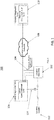
- FIG. 1 is a block diagram of an electric machine health monitoring system 100 for an electric machine 102.
- the health monitoring system 100 comprises an electric supply 112 which provides power to the electric machine 102.
- the local diagnostics unit 106 also collects operational data of the electric supply using sensor set 114. In one particular embodiment, this operational data includes measurements of the voltage and current sent to the electric machine 102 by the electric supply 112. Operational data is transmitted from the electric machine 102 through sensor set 104 to the local diagnostic unit 106, which includes a local computational unit that is configured to receive operational data and perform at least one diagnostic test on the operational data. In one particular embodiment, the operational data measured by sensor set 104 includes one of temperature, vibration signature, and insulation integrity of the electric machine.
- the local diagnostic unit 106 transmits operational data and results of the diagnostic test to a communications network 108.
- the communications network 108 transmits the operational data and the results of the diagnostics to a remote diagnostic unit 110.
- the remote diagnostic unit 110 includes a remote computational unit which is configured to receive both the operational data and local diagnostic unit diagnostic test results from the local diagnostic unit 106.
- the remote diagnostic unit 110 is further configured to perform at least one additional diagnostic test using the operational data and local diagnostic unit diagnostic test result in order to obtain at least one electric machine health status indicator.
- the diagnostic test performed by the local diagnostic unit 106 compares the electric machine operational data and/or the results of the diagnostics test performed by the local diagnostic unit 106 with historical patterns.
- the diagnostic test performed by the local diagnostic unit 106 compares the electric machine operational data and/or the results of the diagnostic test performed by the local diagnostic unit 106 with predetermined thresholds.
- the electric machine health status indicator generated by the remote diagnostic unit 110 compares the electric machine operational data, the results of the diagnostic test performed by the local diagnostic unit and/or the results of the diagnostic test performed by the remote diagnostic unit 110 with historical patterns.
- the electric machine health status indicator generated by the remote diagnostic unit 110 compares the electrical machine operational data, the results the diagnostics test performed by the local diagnostic unit 106, and/or the results of the diagnostic test performed by the remote diagnostic unit 110 with a predetermined threshold.
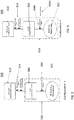
- FIG. 2 is a block diagram of an electric machine health monitoring system 200, wherein multiple local diagnostic units 206a and 206b are connected to a communications network 208. As illustrated in FIG. 2 , electric supplies 212a and 212b are connected to electric machines 202a and 202b and local computational units 206a and 206b, respectively.
- the embodiment illustrated in FIG. 2 differs from the embodiment illustrated in FIG. 1 , wherein multiple local diagnostic units 206a and 206b are connected to the communications network 208.
- the local diagnostic units 206a and 206b both perform the same functions as the local diagnostic unit 106 in FIG. 1 .
- the communications network 208 transmits information from each of the local diagnostic units 206a and 206b to the remote diagnostic unit 210.
- the remote diagnostic unit 210 generates an electric machine health status indicator for each electric machine 202a and 202b according to the information transmitted from local diagnostic units 206a and 206b, respectively.
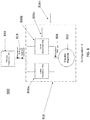
- a method 300 of FIG. 3 of any embodiment, for performing health monitoring and machine performance of the electric machine 102 will be discussed.
- the method 300 begins at acquiring 350 operational data from an electric machine 102 using a local diagnostic unit 106. From acquiring 350, the process continues to performing 360 local diagnostic test. The local diagnostic unit 106 performs a diagnostic test on the operational data. From performing 360, the process continues to transferring 370 operational data and/or diagnostic test.
- the local diagnostic unit 106 transfers the operational data and/or the results of the diagnostics tests performed by the local diagnostic unit 106 to the remote computational unit 110. From transferring 370, the process continues to performing 380 remote diagnostic test.
- the remote diagnostic unit 110 performs a diagnostic test on the operational data and/or the diagnostic test performed by the local diagnostic unit 106.
- the method 300 further comprises an electric machine expert performing a diagnostic test using the operational data from the electric machine 102, the results of the diagnostic test performed by the local diagnostic unit 106, and the results of the diagnostic test performed by the remote diagnostic unit 110.
- the method 300 further comprises a calculation of health status indicator of the electric machine 102 using one or more of the results of a diagnostic test performed by the local diagnostic unit 106, the results of diagnostic test performed by the remote diagnostic unit 110, the result of the diagnostic test performed by the electric machine expert, and/or the electric machine operational data.
- the method further comprises reporting a health status indicator to an end user.
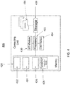
- FIG. 4 is a block diagram of a local diagnostic unit 406, which can include a processor 432 that has a specific structure.
- the specific structure is imparted to the processor 432 by instructions stored in a memory 420 included therein and/or by instructions 436 that can be fetched by the processor 432 from a storage medium 438.
- the storage medium 438 may be co-located with the local computing unit 406 as shown, or it may be located elsewhere and be communicatively coupled to the computing unit 406.
- the local computing unit and remote computing unit are comprised of a computing unit 406 which may include one or more hardware and/or software components configured to fetch, decode, execute, store, analyze, distribute, evaluate, diagnose, and/or categorize information. Furthermore, the local computing unit 406 can include an (input/output) I/O module 430 that can be configured to interface with a plurality of remote devices including sensors.
- a computing unit 406 which may include one or more hardware and/or software components configured to fetch, decode, execute, store, analyze, distribute, evaluate, diagnose, and/or categorize information.
- the local computing unit 406 can include an (input/output) I/O module 430 that can be configured to interface with a plurality of remote devices including sensors.
- the processor 432 may include one or more processing devices or cores (not shown). In some embodiments, the processor 432 may be a plurality of processors, each having either one or more cores.
- the processor 432 can be configured to execute instructions fetched from the memory 420, i.e. from one of memory block 422, memory block 424, or memory block 426, or the instructions may be fetched from storage medium 438, or from a remote device connected to the local computing unit 406 via communication interface 434.
- the storage medium 438 and/or the memory 420 may include a volatile or non-volatile, magnetic, semiconductor, tape, optical, removable, non-removable, read-only, random-access, or any type of non-transitory computer-readable computer medium.
- the storage medium 438 and/or the memory 420 may include programs and/or other information that may be used by the processor 432.
- the storage medium 438 may be configured to log data processed, recorded, or collected during the operation of the computing unit 406.
- the storage medium 438 may store historical patterns, predetermined thresholds, for each of the measurable variables associated with one or more electric machines coupled to the local computing unit 406.
- the data may be time-stamped, location-stamped, cataloged, indexed, or organized in a variety of ways consistent with data storage practice.
- the memory block 428 may be a rotating machine monitoring and diagnostic module.
- the local diagnostic unit 406 may fetch instructions from these modules, which, when executed by the processor 432, cause the processor 432 to perform certain operations.
- the operations may include receiving status data from an electric machine coupled to the local diagnostic unit 406.
- the operations may further include using the status data to both perform a diagnostics test of the electric machine.
- the status data may include measured data associated with at least one of voltage, current, temperature, vibration signature, and insulation integrity of the electric machine.
- the diagnostics test may include comparing the status data with either a historical pattern or a predetermined threshold, or both, based on information stored in the storage medium 438.
- FIG. 5 is a block diagram of an embodiment of the disclosure.
- System 500 illustrates a local group 516.
- Local group 516 comprises an electric machine 502 that transmits operational data 504 to the local diagnostic unit 506.
- the local group 516 transmits operational data and diagnostic test results 514 from the local diagnostic unit 506 to the remote diagnostic unit 510.
- FIG. 6 is a block diagram of an embodiment of the disclosure.
- System 600 is similar to system 500 of FIG. 5 . However, there are more than one units 616n of local group 616.
- the local group 616 comprises electric machine 602 and local diagnostic unit 606, therefore there are more than one of electric machines 602 and local diagnostic units 606. All of the local groups 616 transmit operational data and/or diagnostic test results into one remote diagnostic unit 610.
- System 600 further comprises transmission of operational data 604a from the electric machine 602 to the local computational unit 606.
- the local diagnostic unit 606 transmits operational data and/or diagnostic test results 614 to the remote diagnostic unit 610.
- FIG. 7 is a block diagram of an embodiment of the disclosure.
- System 700 comprises a local group 716.
- the local group 716 comprises more than one units 702n of electric machines 702a and 702b connected to a single local diagnostic unit 706.
- the local diagnostic unit 706 in each local group 716n transmits operational data and/or diagnostic test results 714 to the remote diagnostic unit 710.
- System 700 further comprises transmission of operational data 704a and 704b from the electric machines 702a and 702b to the local computational unit 706.
- FIG. 8 is a block diagram of an embodiment of the disclosure.
- System 800 comprises a local group 816.
- the local group 816 comprises an electric machine 802 that transmits operational data 804 to two local diagnostic units 806a and 806b. Both local diagnostic units 806a and 806b transmit operational data and/or diagnostics test results 814 into a remote diagnostic unit 810.
- FIG. 9 is a block diagram of an embodiment of the disclosure.
- System 900 comprises a local group 916.
- the local group 916 comprises an electric machine 902 that transmits two sets of operational data 904a and 904b to two different local diagnostic units 906a and 906b.
- a plurality of time sequenced operational data, asset performance, and health status indicators are transferred from a local CPU cores 406 to a communications network 130 and then transferred to a remote diagnostic unit 110.
- a remote diagnostic unit 110 performs additional diagnostic analysis and trends on a plurality of time sequenced operational information based on the asset performance and health status indicators.
- more than one rotating machine monitoring and diagnostic unit 428 and local CPU cores 406 may be coupled to the communications network 108 and the remote computing unit 110.
- an electric machine 102 is coupled to sensor(s).
- the sensor(s) are located adjacent to an electric machine 102.
- the sensor(s) are configured to monitor one or more parameters of an electric machine 102, such as current, voltage, vibrations, temperature, etc.
- the sensor(s) are coupled to a local diagnostic unit 406.
- Local diagnostic unit 406 includes a data acquisition component and a rotating machine diagnostic algorithms component 428.
- the data acquisition component acquires data from sensor(s).
- the data acquisition component also transmits data to the adjacent rotating machine diagnostic algorithms component 428.
- a transmitter is coupled to a rotating machine diagnostic algorithms components 428.
- the transmitter is also coupled to a remote diagnostic unit 240.
- the remote diagnostic unit 110 includes a time sequenced operational data component, a health status indicators component, a remote diagnostic algorithms component 428, and a combined machine health status component 242.
Landscapes
- Engineering & Computer Science (AREA)
- Theoretical Computer Science (AREA)
- General Physics & Mathematics (AREA)
- Physics & Mathematics (AREA)
- General Engineering & Computer Science (AREA)
- Quality & Reliability (AREA)
- Automation & Control Theory (AREA)
- Health & Medical Sciences (AREA)
- Biomedical Technology (AREA)
- Computer Hardware Design (AREA)
- Computing Systems (AREA)
- Testing And Monitoring For Control Systems (AREA)
- Testing Of Devices, Machine Parts, Or Other Structures Thereof (AREA)
Abstract
Description
- The present disclosure relates to diagnosing and reporting conditions and health status of industrial assets. In particular, the present disclosure relates to a system and method for determining electric machine performance and health status.
- Electric machine diagnostics and monitoring is commonly performed to identify current health and performance status of an electric machine. Traditional machine health monitoring systems perform diagnostics on a local diagnostic unit. The local diagnostic unit comprises a local computational unit which receives sensor data, performs at least one local diagnostic test on the sensor data, and outputs the machine status indicator. The outputs of these systems can be sent to a customer network, or to remote experts. If machine operational data is available, the remote experts are able to determine the severity of any faults indicated and report back to a customer. This requires the experts to design the machine diagnostic algorithms, and also expert personnel to fill the remote service agreement.
- In other traditional machine health monitoring systems, data acquisition is performed locally and the data is sent to a remote diagnostic unit where the health status can be determined by a machine expert. The machine expert has access to all the information about the machine. However, challenges occur when transmitting high bandwidth data to a remote server. Unfortunately, data fidelity may be lost during transmission.
- Given the aforementioned deficiencies, a need exists for a health monitoring system for an electric machine, including a software module for diagnostic software techniques within a remote diagnostic unit. More specifically, a need exists for a system that collects and analyzes operational data locally, and transmits the data to a remote diagnostic unit for additional diagnostic analysis.
- One embodiment provides a system that includes an electric machine, a data acquisition component, a local transmitter, a communications network, and a remote diagnostic unit. The remote diagnostic unit includes a remote computational unit and is configured to receive time sequenced operational information, asset performance, and health status indicators from the local transmitter. The remote diagnostic unit can assess the health status given by the local system by executing one or more remote diagnostic tests to obtain a health status indicator, and a remote expert can compare the health status indicator with time sequenced operational data to perform expert analysis. Additionally, the remote diagnostic unit can leverage fleet diagnostics when many similar machines are connected to the remote computing unit network. Commercially, embodiments of the system perform as both a standalone system and a remote service tool.
- In certain embodiments, a method using this system shall perform all diagnostic analysis on a local diagnostic unit which includes a remote computational unit and uses the high bandwidth operational data collected from a sensor to determine electric machine performance and health status by executing one or more local diagnostic tests. The local diagnostic unit transmits the status indicators, as well as time sequenced raw operational data, to a transmitter and/or communication network. The transmitter/communication network transmits indicators and data to the remote computational unit. The remote diagnostic unit performs additional machine diagnostics based on the current health status of the machine determined by the local diagnostic unit and on the operational data sent from the local diagnostic unit.
- Additional features, modes of operations, advantages, and other aspects of various embodiments are described below with reference to the accompanying drawings. It is noted that the present disclosure is not limited to the specific embodiments described herein. These embodiments are presented for illustrative purposes only. Additional embodiments, or modifications of the embodiments disclosed, will be readily apparent to persons skilled in the relevant art(s) based on the teachings provided.
- Illustrative embodiments may take form in various components and arrangements of components. Illustrative embodiments are shown in the accompanying drawings, throughout which like reference numerals may indicate corresponding or similar parts in the various drawings. The drawings are only for purposes of illustrating the embodiments and are not to be construed as limiting the disclosure. Given the following enabling description of the drawings, the novel aspects of the present disclosure should become evident to a person of ordinary skill in the relevant art(s).
-
FIG. 1 is a block diagram of a health monitoring system including a remote diagnostic unit in accordance with the embodiments. -
FIG. 2 is a block diagram of the health monitoring system including multiple local diagnostic units and electric machines in accordance with an embodiment of this disclosure. -
FIG. 3 is a flow diagram illustrating an exemplary method of practicing the embodiments. -
FIG. 4 is a block diagram of a local diagnostic unit. -
FIG. 5 is a block diagram of health monitoring system in accordance with an embodiment of this disclosure. -
FIG. 6 is a block diagram of a health monitoring system in accordance with an embodiment of this disclosure. -
FIG. 7 is a block diagram of a health monitoring system in accordance with an embodiment of this disclosure. -
FIG. 8 is a block diagram of a health monitoring system in accordance with an embodiment of this disclosure. -
FIG. 9 is a block diagram of a health monitoring system in accordance with an embodiment of this disclosure. - While the illustrative embodiments are described herein for particular applications, it should be understood that the present disclosure is not limited thereto. Those skilled in the art and with access to the teachings provided herein will recognize additional applications, modifications, and embodiments within the scope thereof and additional fields in which the present disclosure would be of significant utility.
- Reference will be made below in detail to exemplary embodiments of the inventive subject matter, examples of which are illustrated in the accompanying drawings. Wherever possible, the same reference numerals used throughout the drawings refer to the same or like parts.
- Embodiments of the invention provide a health monitoring system including diagnostic techniques.
-
FIG. 1 is a block diagram of an electric machinehealth monitoring system 100 for anelectric machine 102. Thehealth monitoring system 100 comprises anelectric supply 112 which provides power to theelectric machine 102. Thelocal diagnostics unit 106 also collects operational data of the electric supply using sensor set 114. In one particular embodiment, this operational data includes measurements of the voltage and current sent to theelectric machine 102 by theelectric supply 112. Operational data is transmitted from theelectric machine 102 through sensor set 104 to the localdiagnostic unit 106, which includes a local computational unit that is configured to receive operational data and perform at least one diagnostic test on the operational data. In one particular embodiment, the operational data measured bysensor set 104 includes one of temperature, vibration signature, and insulation integrity of the electric machine. The localdiagnostic unit 106 transmits operational data and results of the diagnostic test to acommunications network 108. Thecommunications network 108 transmits the operational data and the results of the diagnostics to a remotediagnostic unit 110. The remotediagnostic unit 110 includes a remote computational unit which is configured to receive both the operational data and local diagnostic unit diagnostic test results from the localdiagnostic unit 106. The remotediagnostic unit 110 is further configured to perform at least one additional diagnostic test using the operational data and local diagnostic unit diagnostic test result in order to obtain at least one electric machine health status indicator. - The diagnostic test performed by the local
diagnostic unit 106 compares the electric machine operational data and/or the results of the diagnostics test performed by the localdiagnostic unit 106 with historical patterns. - The diagnostic test performed by the local
diagnostic unit 106 compares the electric machine operational data and/or the results of the diagnostic test performed by the localdiagnostic unit 106 with predetermined thresholds. - The electric machine health status indicator generated by the remote
diagnostic unit 110 compares the electric machine operational data, the results of the diagnostic test performed by the local diagnostic unit and/or the results of the diagnostic test performed by the remotediagnostic unit 110 with historical patterns. - The electric machine health status indicator generated by the remote
diagnostic unit 110 compares the electrical machine operational data, the results the diagnostics test performed by the localdiagnostic unit 106, and/or the results of the diagnostic test performed by the remotediagnostic unit 110 with a predetermined threshold. -
FIG. 2 is a block diagram of an electric machinehealth monitoring system 200, wherein multiple localdiagnostic units communications network 208. As illustrated inFIG. 2 ,electric supplies electric machines computational units -
Electric machines computational units transmitters diagnostic units electric machines electric supplies - The embodiment illustrated in
FIG. 2 differs from the embodiment illustrated inFIG. 1 , wherein multiple localdiagnostic units communications network 208. The localdiagnostic units diagnostic unit 106 inFIG. 1 . Thecommunications network 208 transmits information from each of the localdiagnostic units diagnostic unit 210. The remotediagnostic unit 210 generates an electric machine health status indicator for eachelectric machine diagnostic units - A
method 300 ofFIG. 3 of any embodiment, for performing health monitoring and machine performance of theelectric machine 102 will be discussed. Themethod 300 begins at acquiring 350 operational data from anelectric machine 102 using a localdiagnostic unit 106. From acquiring 350, the process continues to performing 360 local diagnostic test. The localdiagnostic unit 106 performs a diagnostic test on the operational data. From performing 360, the process continues to transferring 370 operational data and/or diagnostic test. - The local
diagnostic unit 106 transfers the operational data and/or the results of the diagnostics tests performed by the localdiagnostic unit 106 to the remotecomputational unit 110. From transferring 370, the process continues to performing 380 remote diagnostic test. The remotediagnostic unit 110 performs a diagnostic test on the operational data and/or the diagnostic test performed by the localdiagnostic unit 106. - The
method 300 further comprises an electric machine expert performing a diagnostic test using the operational data from theelectric machine 102, the results of the diagnostic test performed by the localdiagnostic unit 106, and the results of the diagnostic test performed by the remotediagnostic unit 110. - The
method 300 further comprises a calculation of health status indicator of theelectric machine 102 using one or more of the results of a diagnostic test performed by the localdiagnostic unit 106, the results of diagnostic test performed by the remotediagnostic unit 110, the result of the diagnostic test performed by the electric machine expert, and/or the electric machine operational data. The method further comprises reporting a health status indicator to an end user. -
FIG. 4 is a block diagram of a localdiagnostic unit 406, which can include aprocessor 432 that has a specific structure. The specific structure is imparted to theprocessor 432 by instructions stored in amemory 420 included therein and/or byinstructions 436 that can be fetched by theprocessor 432 from astorage medium 438. Thestorage medium 438 may be co-located with thelocal computing unit 406 as shown, or it may be located elsewhere and be communicatively coupled to thecomputing unit 406. - The local computing unit and remote computing unit are comprised of a
computing unit 406 which may include one or more hardware and/or software components configured to fetch, decode, execute, store, analyze, distribute, evaluate, diagnose, and/or categorize information. Furthermore, thelocal computing unit 406 can include an (input/output) I/O module 430 that can be configured to interface with a plurality of remote devices including sensors. - The
processor 432 may include one or more processing devices or cores (not shown). In some embodiments, theprocessor 432 may be a plurality of processors, each having either one or more cores. Theprocessor 432 can be configured to execute instructions fetched from thememory 420, i.e. from one ofmemory block 422,memory block 424, ormemory block 426, or the instructions may be fetched fromstorage medium 438, or from a remote device connected to thelocal computing unit 406 viacommunication interface 434. - Furthermore, without loss of generality, the
storage medium 438 and/or thememory 420 may include a volatile or non-volatile, magnetic, semiconductor, tape, optical, removable, non-removable, read-only, random-access, or any type of non-transitory computer-readable computer medium. Thestorage medium 438 and/or thememory 420 may include programs and/or other information that may be used by theprocessor 432. - Moreover, the
storage medium 438 may be configured to log data processed, recorded, or collected during the operation of thecomputing unit 406. For example, thestorage medium 438 may store historical patterns, predetermined thresholds, for each of the measurable variables associated with one or more electric machines coupled to thelocal computing unit 406. The data may be time-stamped, location-stamped, cataloged, indexed, or organized in a variety of ways consistent with data storage practice. - In an embodiment, the
memory block 428 may be a rotating machine monitoring and diagnostic module. As such, the localdiagnostic unit 406 may fetch instructions from these modules, which, when executed by theprocessor 432, cause theprocessor 432 to perform certain operations. The operations may include receiving status data from an electric machine coupled to the localdiagnostic unit 406. - The operations may further include using the status data to both perform a diagnostics test of the electric machine. The status data may include measured data associated with at least one of voltage, current, temperature, vibration signature, and insulation integrity of the electric machine. The diagnostics test may include comparing the status data with either a historical pattern or a predetermined threshold, or both, based on information stored in the
storage medium 438. -
FIG. 5 is a block diagram of an embodiment of the disclosure.System 500 illustrates alocal group 516.Local group 516 comprises anelectric machine 502 that transmitsoperational data 504 to the localdiagnostic unit 506. Thelocal group 516 transmits operational data anddiagnostic test results 514 from the localdiagnostic unit 506 to the remotediagnostic unit 510. -
FIG. 6 is a block diagram of an embodiment of the disclosure.System 600 is similar tosystem 500 ofFIG. 5 . However, there are more than oneunits 616n oflocal group 616. Thelocal group 616 compriseselectric machine 602 and localdiagnostic unit 606, therefore there are more than one ofelectric machines 602 and localdiagnostic units 606. All of thelocal groups 616 transmit operational data and/or diagnostic test results into one remotediagnostic unit 610.System 600 further comprises transmission ofoperational data 604a from theelectric machine 602 to the localcomputational unit 606. The localdiagnostic unit 606 transmits operational data and/ordiagnostic test results 614 to the remotediagnostic unit 610. -
FIG. 7 is a block diagram of an embodiment of the disclosure.System 700 comprises alocal group 716. Thelocal group 716 comprises more than oneunits 702n ofelectric machines diagnostic unit 706. There are more than oneunits 716n oflocal groups 716 connected to a single remotediagnostic unit 710. The localdiagnostic unit 706 in eachlocal group 716n transmits operational data and/ordiagnostic test results 714 to the remotediagnostic unit 710.
System 700 further comprises transmission ofoperational data electric machines computational unit 706. -
FIG. 8 is a block diagram of an embodiment of the disclosure.System 800 comprises alocal group 816. Thelocal group 816 comprises anelectric machine 802 that transmitsoperational data 804 to two localdiagnostic units diagnostic units results 814 into a remotediagnostic unit 810. In any embodiment, there are more than oneunits 806n of local diagnostic units. Furthermore, there are more than oneunits 816n oflocal groups 816 attached to the remotediagnostic unit 810. -
FIG. 9 is a block diagram of an embodiment of the disclosure.System 900 comprises alocal group 916. Thelocal group 916 comprises anelectric machine 902 that transmits two sets ofoperational data diagnostic units electric machines 902n and multiple sets ofoperational data 904n. In certain embodiments, there are more than oneunit 906n of local diagnostic units. All of the localdiagnostic units diagnostic test results 914 to a remotediagnostic unit 910. Furthermore, it is possible to have more than oneunit 916n oflocal groups 916 that transmit operational data and/ordiagnostic test results 914 to the remotediagnostic unit 910. - A plurality of time sequenced operational data, asset performance, and health status indicators are transferred from a
local CPU cores 406 to a communications network 130 and then transferred to a remotediagnostic unit 110. A remotediagnostic unit 110 performs additional diagnostic analysis and trends on a plurality of time sequenced operational information based on the asset performance and health status indicators. In an embodiment, more than one rotating machine monitoring anddiagnostic unit 428 andlocal CPU cores 406 may be coupled to thecommunications network 108 and theremote computing unit 110. - In certain embodiments, an
electric machine 102 is coupled to sensor(s). The sensor(s) are located adjacent to anelectric machine 102. The sensor(s) are configured to monitor one or more parameters of anelectric machine 102, such as current, voltage, vibrations, temperature, etc. The sensor(s) are coupled to a localdiagnostic unit 406. Localdiagnostic unit 406 includes a data acquisition component and a rotating machinediagnostic algorithms component 428. The data acquisition component acquires data from sensor(s). The data acquisition component also transmits data to the adjacent rotating machinediagnostic algorithms component 428. A transmitter is coupled to a rotating machinediagnostic algorithms components 428. The transmitter is also coupled to a remote diagnostic unit 240. The remotediagnostic unit 110 includes a time sequenced operational data component, a health status indicators component, a remotediagnostic algorithms component 428, and a combined machine health status component 242. - Those skilled in the relevant art(s) will appreciate that various adaptations and modifications of the embodiments described above can be configured without departing from the scope and spirit of the disclosure. Therefore, it is to be understood that, within the scope of the appended claims, the disclosure may be practiced other than as specifically described herein.
Claims (15)
- A health monitoring system (100) for an electric machine (102), comprising:a first electric machine (202a);a first local diagnostic unit (206a), wherein the first local diagnostic (206a) unit includes a local computational (206a) unit which is configured to receive a first set of operational data (350) from the first electric machine (202a) and perform a first local diagnostic test (360) on the first set of operational data (350); anda remote diagnostic unit (210), wherein the remote diagnostic unit (210) includes a remote computational unit (210) which is configured to receive the operational data (350) and the first local computational (206a) unit diagnostic test result (370) from the first local diagnostic unit (206a), wherein the remote computational unit (210) is further configured to perform a remote diagnostic test (380) using the first set of operational data (350) and the first local diagnostic test (360) result to obtain an electric machine health status indicator.
- The health monitoring system (100) of claim 1, wherein the first electric machine (102) is connected to the first local diagnostic unit (106), and the remote diagnostic unit (110) is connected to the first local diagnostic unit (106).
- The health monitoring system (100) of claim 1 or 2, wherein the first local diagnostic test (360) compares the first set of operational data (350) and the results of the first diagnostics test (360) with historical patterns.
- The health monitoring system (100) of any of claims 1 to 3, wherein the first diagnostic test (360) compares the first set of operational data (350) and the results of the first diagnostic test (360) with predetermined thresholds.
- The health monitoring system (100) of any preceding claim, wherein the electric machine health status indicator compares the first set of operational data (350), the results of the first local diagnostics test (360), and the results of the remote diagnostics test (380) with historical patterns.
- The health monitoring system (100) of any preceding claim, wherein the electric machine health status indicator compares the first set of operational data (350), the results the first diagnostics test (360), and the results of the remote diagnostics test (380) with a predetermined threshold.
- The health monitoring system (100) of any preceding claim, further comprising a second electric machine (202b) and second local diagnostic unit (206b), the second electric machine (202b) is connected to the second diagnostic unit (206b), the second diagnostic unit (206b) is connected to the remote diagnostic unit (210).
- The health monitoring system (100) of claim 7, wherein the second local diagnostic unit (206b) is configured to receive a second set of operational data from the second electric machine (202b) and perform a second local diagnostic test on the second set of operational data, wherein the remote diagnostic unit (210) is further configured receive the second set of operational data and the results of the second local diagnostic test.
- The health monitoring system (100) of any of claims 1 to 6, further comprising a second electric machine (702b), wherein the second electric machine (702b) is connected to the first local diagnostic unit (706).
- The health monitoring system (100) of claim 9, wherein the first local diagnostic unit (706) is further configured to receive a second set of operational data from the second electric machine (702b).
- The health monitoring system (100) of any of claims 1 to 6, further comprising a second local diagnostic unit (806b), wherein the first electric machine (802) is connected to the second local diagnostic unit (806b), wherein second local computational unit (806b) is connected to the remote diagnostic unit (810).
- The health monitoring system (100) of claim 11, wherein the second local diagnostic unit (806b) is configured to receive the first set of operational data from the first electric machine (802).
- The health monitoring system (100) of claim 11 or 12, wherein the second local diagnostic unit (906b) is configured to receive a second set of operational data from the first electric machine (902).
- A method for determining performance and health status of an electric machine (102), comprising:acquiring a first operational data set (350) from a first electric machine (202a) using a first local diagnostic unit (206a);performing a first local diagnostic test (360) on the first operational data set (350) using the first local diagnostic unit (206a);transferring the first operational data set (370) and the first local diagnostic tests results (370) performed by the first local diagnostic unit (206a) from the first local diagnostic unit (206a) to a remote diagnostic unit (210); andperforming a remote diagnostic test (380) on at least one of the first operational data set and (350) the first local diagnostic test results (360) using the remote diagnostic unit (210).
- The method of claim 14, further comprising performing an expert diagnostic test using at least one of the first operational data set (350), the first diagnostic test results (360), and the remote diagnostic test results (380) by an electric machine expert.
Applications Claiming Priority (1)
| Application Number | Priority Date | Filing Date | Title |
|---|---|---|---|
| US15/484,732 US10481968B2 (en) | 2017-04-11 | 2017-04-11 | Method and system for determining and reporting equipment operating conditions and health status |
Publications (1)
| Publication Number | Publication Date |
|---|---|
| EP3388912A1 true EP3388912A1 (en) | 2018-10-17 |
Family
ID=61731623
Family Applications (1)
| Application Number | Title | Priority Date | Filing Date |
|---|---|---|---|
| EP18162921.3A Withdrawn EP3388912A1 (en) | 2017-04-11 | 2018-03-20 | Method and system for determining and reporting equipment operating conditions and health status |
Country Status (2)
| Country | Link |
|---|---|
| US (1) | US10481968B2 (en) |
| EP (1) | EP3388912A1 (en) |
Families Citing this family (1)
| Publication number | Priority date | Publication date | Assignee | Title |
|---|---|---|---|---|
| CN115963765B (en) * | 2023-02-07 | 2024-08-13 | 北京计算机技术及应用研究所 | A health management system based on domestic single chip microcomputer |
Citations (3)
| Publication number | Priority date | Publication date | Assignee | Title |
|---|---|---|---|---|
| US5988986A (en) * | 1996-09-28 | 1999-11-23 | Maag Pump Systems Textron Ag | Method and device for monitoring system units based on transmission of lumped characteristic numbers |
| US6199018B1 (en) * | 1998-03-04 | 2001-03-06 | Emerson Electric Co. | Distributed diagnostic system |
| EP1168130A1 (en) * | 2000-06-22 | 2002-01-02 | Hitachi, Ltd. | Remote monitoring diagnostic system and method |
Family Cites Families (4)
| Publication number | Priority date | Publication date | Assignee | Title |
|---|---|---|---|---|
| US20030046382A1 (en) * | 2001-08-21 | 2003-03-06 | Sascha Nick | System and method for scalable multi-level remote diagnosis and predictive maintenance |
| US20040199573A1 (en) * | 2002-10-31 | 2004-10-07 | Predictive Systems Engineering, Ltd. | System and method for remote diagnosis of distributed objects |
| US8583597B2 (en) | 2011-11-16 | 2013-11-12 | General Electric Company | System and method for on-site monitoring data archival |
| US9245116B2 (en) | 2013-03-21 | 2016-01-26 | General Electric Company | Systems and methods for remote monitoring, security, diagnostics, and prognostics |
-
2017
- 2017-04-11 US US15/484,732 patent/US10481968B2/en active Active
-
2018
- 2018-03-20 EP EP18162921.3A patent/EP3388912A1/en not_active Withdrawn
Patent Citations (3)
| Publication number | Priority date | Publication date | Assignee | Title |
|---|---|---|---|---|
| US5988986A (en) * | 1996-09-28 | 1999-11-23 | Maag Pump Systems Textron Ag | Method and device for monitoring system units based on transmission of lumped characteristic numbers |
| US6199018B1 (en) * | 1998-03-04 | 2001-03-06 | Emerson Electric Co. | Distributed diagnostic system |
| EP1168130A1 (en) * | 2000-06-22 | 2002-01-02 | Hitachi, Ltd. | Remote monitoring diagnostic system and method |
Also Published As
| Publication number | Publication date |
|---|---|
| US20180293124A1 (en) | 2018-10-11 |
| US10481968B2 (en) | 2019-11-19 |
Similar Documents
| Publication | Publication Date | Title |
|---|---|---|
| CN114255784B (en) | Substation equipment fault diagnosis method and related device based on voiceprint recognition | |
| CN108805359A (en) | A kind of failure pre-judging method and device | |
| CN117060409B (en) | Automatic detection and analysis method and system for power line operating status | |
| CN108900319B (en) | Fault detection method and device | |
| CN108985279A (en) | The method for diagnosing faults and device of double-unit traction controller waveform | |
| JP2011520170A (en) | Method for identifying behavior predictions for a system | |
| US20220308572A1 (en) | System and method for determining a health condition and an anomaly of an equipment using one or more sensors | |
| CN117375239A (en) | A safe operation monitoring method and system for power transmission and transformation equipment | |
| CN118607980A (en) | Cable health state evaluation method and system | |
| CN115566804A (en) | Electric power monitoring system based on distributed optical fiber sensing technology | |
| CN116300835A (en) | Automatic detection equipment remote diagnosis system based on Internet | |
| CN114091618A (en) | Industrial equipment health status diagnosis management method, device and server | |
| CN118606791A (en) | Smart park management method based on multimodal fusion | |
| CN113992602B (en) | Cable monitoring data uploading method, device, equipment and storage medium | |
| CN116684327B (en) | Mountain area communication network fault monitoring and evaluating method based on cloud computing | |
| CN117906911A (en) | Coupling performance monitoring method for optical chip and tail fiber coupling device | |
| CN114034972A (en) | Intelligent cable fault determination method and device based on image data | |
| US10481968B2 (en) | Method and system for determining and reporting equipment operating conditions and health status | |
| CN119165275B (en) | Power equipment detection method, device, equipment and storage medium | |
| CN117993895B (en) | Full life cycle management system of power grid equipment | |
| US11366178B2 (en) | Method and system for diagnostics and monitoring of electric machines | |
| BR112019009926B1 (en) | METHOD AND ADAPTED APPARATUS FOR PREDICTING A LIFE CYCLE OF A CC CIRCUIT | |
| CA2793952C (en) | Extracting data related to clinical diagnostic instruments | |
| CN114153676B (en) | Configuration optimization method of service grid system and related equipment | |
| CN113972631B (en) | An intelligent alarm method and system for a relay protection master station |
Legal Events
| Date | Code | Title | Description |
|---|---|---|---|
| PUAI | Public reference made under article 153(3) epc to a published international application that has entered the european phase |
Free format text: ORIGINAL CODE: 0009012 |
|
| STAA | Information on the status of an ep patent application or granted ep patent |
Free format text: STATUS: THE APPLICATION HAS BEEN PUBLISHED |
|
| AK | Designated contracting states |
Kind code of ref document: A1 Designated state(s): AL AT BE BG CH CY CZ DE DK EE ES FI FR GB GR HR HU IE IS IT LI LT LU LV MC MK MT NL NO PL PT RO RS SE SI SK SM TR |
|
| AX | Request for extension of the european patent |
Extension state: BA ME |
|
| STAA | Information on the status of an ep patent application or granted ep patent |
Free format text: STATUS: REQUEST FOR EXAMINATION WAS MADE |
|
| 17P | Request for examination filed |
Effective date: 20190417 |
|
| RBV | Designated contracting states (corrected) |
Designated state(s): AL AT BE BG CH CY CZ DE DK EE ES FI FR GB GR HR HU IE IS IT LI LT LU LV MC MK MT NL NO PL PT RO RS SE SI SK SM TR |
|
| STAA | Information on the status of an ep patent application or granted ep patent |
Free format text: STATUS: EXAMINATION IS IN PROGRESS |
|
| 17Q | First examination report despatched |
Effective date: 20200217 |
|
| STAA | Information on the status of an ep patent application or granted ep patent |
Free format text: STATUS: THE APPLICATION IS DEEMED TO BE WITHDRAWN |
|
| 18D | Application deemed to be withdrawn |
Effective date: 20210721 |