EP3388883A1 - Virtual reality glasses - Google Patents
Virtual reality glasses Download PDFInfo
- Publication number
- EP3388883A1 EP3388883A1 EP18166448.3A EP18166448A EP3388883A1 EP 3388883 A1 EP3388883 A1 EP 3388883A1 EP 18166448 A EP18166448 A EP 18166448A EP 3388883 A1 EP3388883 A1 EP 3388883A1
- Authority
- EP
- European Patent Office
- Prior art keywords
- glasses
- electronic device
- cover plate
- receiving space
- support pad
- Prior art date
- Legal status (The legal status is an assumption and is not a legal conclusion. Google has not performed a legal analysis and makes no representation as to the accuracy of the status listed.)
- Granted
Links
Images
Classifications
-
- G—PHYSICS
- G06—COMPUTING OR CALCULATING; COUNTING
- G06F—ELECTRIC DIGITAL DATA PROCESSING
- G06F3/00—Input arrangements for transferring data to be processed into a form capable of being handled by the computer; Output arrangements for transferring data from processing unit to output unit, e.g. interface arrangements
- G06F3/01—Input arrangements or combined input and output arrangements for interaction between user and computer
- G06F3/011—Arrangements for interaction with the human body, e.g. for user immersion in virtual reality
-
- G—PHYSICS
- G02—OPTICS
- G02B—OPTICAL ELEMENTS, SYSTEMS OR APPARATUS
- G02B27/00—Optical systems or apparatus not provided for by any of the groups G02B1/00 - G02B26/00, G02B30/00
- G02B27/01—Head-up displays
- G02B27/017—Head mounted
- G02B27/0176—Head mounted characterised by mechanical features
-
- A—HUMAN NECESSITIES
- A45—HAND OR TRAVELLING ARTICLES
- A45F—TRAVELLING OR CAMP EQUIPMENT: SACKS OR PACKS CARRIED ON THE BODY
- A45F5/00—Holders or carriers for hand articles; Holders or carriers for use while travelling or camping
-
- G—PHYSICS
- G06—COMPUTING OR CALCULATING; COUNTING
- G06F—ELECTRIC DIGITAL DATA PROCESSING
- G06F1/00—Details not covered by groups G06F3/00 - G06F13/00 and G06F21/00
- G06F1/16—Constructional details or arrangements
- G06F1/1601—Constructional details related to the housing of computer displays, e.g. of CRT monitors, of flat displays
- G06F1/1605—Multimedia displays, e.g. with integrated or attached speakers, cameras, microphones
-
- A—HUMAN NECESSITIES
- A45—HAND OR TRAVELLING ARTICLES
- A45F—TRAVELLING OR CAMP EQUIPMENT: SACKS OR PACKS CARRIED ON THE BODY
- A45F5/00—Holders or carriers for hand articles; Holders or carriers for use while travelling or camping
- A45F5/1516—Holders or carriers for portable handheld communication devices, e.g. pagers or smart phones
-
- A—HUMAN NECESSITIES
- A45—HAND OR TRAVELLING ARTICLES
- A45F—TRAVELLING OR CAMP EQUIPMENT: SACKS OR PACKS CARRIED ON THE BODY
- A45F5/00—Holders or carriers for hand articles; Holders or carriers for use while travelling or camping
- A45F5/1525—Holders or carriers for portable computing devices, e.g. laptops, tablets or calculators
Definitions
- the present disclosure generally relates to the technical field of Virtual Reality (VR), and more particularly, to VR glasses.
- VR Virtual Reality
- Virtual reality (VR) technology involves a computer simulation system capable of generating a simulated environment and providing a user with an immersive application experience by means of a three-dimensional dynamic visual scene, entity behavior interaction, and the like.
- a simple and low-cost VR solution which provides VR glasses including a VR function component and provides playing back of VR contents through a user's electronic device, such as a smart phone or a tablet.
- the present disclosure provides VR glasses which overcome the shortcomings in the related technology.
- VR glasses including a glasses body; a cover plate fixedly attached to the glasses body; and a receiving space formed between the glasses body and the cover plate, wherein the receiving space is configured to receive an electronic device, wherein a support pad is provided on a side of the cover plate that is facing the glasses body, wherein a surface of the support pad includes a plurality of projections, such that when the electronic device is placed into the receiving space, the plurality of projections are configured to deform and generate a support force towards the electronic device, so as to press against and hold the electronic device in the receiving space.
- the support force at least has a component, which is directed towards the glasses body, thereby pressing the electronic device towards the glasses body when the electronic device is placed in the receiving space. It is further preferred that the support force is a normal force relative to the glasses body.
- the support pad includes a first fitting surface facing the cover plate, and the first fitting surface has protrusions towards the cover plate to form the plurality of projections.
- a recess in particular towards the glasses body, is formed in the first fitting surface, and the plurality of projections are positioned on a bottom surface of the recess.
- the plurality of projections include one or more protruding ribs.
- the protruding ribs are arranged along a width direction or a height direction of the cover plate.
- the plurality of projections include one or more bumps.
- the support pad includes a first fitting surface that is facing the cover plate; and retaining protrusions that are provided in an edge region of the first fitting surface, wherein the retaining protrusions are configured to be engaged in clamping grooves in a surface of the cover plate to assemble the support pad on the cover plate.
- the support pad further includes a second fitting surface facing the glasses body, wherein the second fitting surface includes a guiding part and a pressing part, wherein the guiding part is configured to guide the electronic device being arranged in the receiving space, and wherein the electronic device is pressed against by the pressing part after being arranged in the receiving space.
- the guiding part includes a slope facing an opening direction of the receiving space.
- the support pad is made of silica gel material.
- the projections in the present disclosure may be deformed under an action of an external assembling force, and generate the support force acting on the electronic device, thereby increasing a support force transferred from a cover plate side to the electronic device, stabilizing a relative position of the electronic device in the receiving space, and avoiding shaking of the electronic device caused as the VR glasses are moved, which would lead to a deviation of a played content relative to a user's sight line and influence the user's immersive experience.
- first, second, third and the like may be adopted to describe various elements in the present disclosure, but the elements should not be limited to these terms. These terms are only adopted to distinguish elements of the same type.
- first element may also be known as the second element, and similarly, the second element may also be known as the first element, depending on a context.
- a word “if' used here may be explained as “while”, “when” or “in response to”.
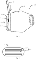
- Fig. 1 shows virtual reality (VR) glasses according to an exemplary aspect.
- the VR glasses 100 may include a glasses body 1 and a cover plate 2.
- the glasses body 1 is fixedly connected with the cover plate 2 to form a receiving space 11 receiving an electronic device 3 after connection.
- the receiving space 11 has an opening direction A as shown in Fig. 1 , so that the electronic device 3 can be placed into the receiving space 11 along the opening direction A.
- a screen of the electronic device 3 faces the glasses body 1, and a rear panel faces the cover plate 2, so that a user can watch a played content of the electronic device 3 after wearing the VR glasses.
- a support pad 4 may be arranged on the side of the cover plate 2 facing the glasses body 1, so as to support the rear panel of the electronic device 3 by the support pad 4.
- a plurality of projections 41 may be arranged on a surface of the support pad 4.
- the plurality of projections 41 may be deformed under an action of an external assembling force, thereby generating an support force F facing the electronic device 3.
- the support force F may act on the rear panel of the electronic device 3 along a direction shown by an arrow in Fig. 1 , and under an action of the support force F, the electronic device 3 can be pressed against and held in the receiving space 11, so as to keep the electronic device 3 being fitted in the glasses body 1.
- the projections 41 on the support pad 4 can be deformed under the action of the external assembling force, and exert the support force F which is generated accordingly on the electronic device 3.
- the deformation can be amplified. Therefore a support force transferred from a cover plate 2 side to the electronic device 3 is increased, and the relative position of the electronic device 3 in the receiving space 11 is stabilized. Shaking of the electronic device 3 caused as the VR glasses are moved is avoided, which would lead to a deviation of the played content relative to the user's sight line, and then influence the user's immersive experience.
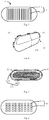
- the plurality of projections 41 may include one or more projections, for example protruding ribs 411 and 412 arranged along a width direction of the cover plate 2, as shown in Fig. 2 .
- the aspect of the present disclosure here only gives exemplary description, but not limits the number and shape of the projection.
- the protruding ribs 411 and 412 may also be arranged along a height direction of the cover plate 2 as shown in Fig. 3 , or may be arranged at acute angles width direction or height direction of the cover plate 2. This is not limited in the aspect of the present disclosure.
- the protruding ribs 411 and 412 may be formed by extensions towards the cover plate 2 from a first fitting surface 42 of the support pad 4, which is on the side, facing the cover plate 2, of the support pad 4, as shown in Fig. 4 , so as to provide the support force F without influencing assembling of the electronic device 3.
- a recess 421 may be formed in a surface of the first fitting surface 42, and the protruding ribs 411 and 412 are arranged on a bottom surface of the recess 421, as shown in Fig.
- the protruding ribs 411 and 412 may alternatively be formed by extensions towards the glasses body 1 from a second fitting surface 43 of the support pad 4, which is on the side, facing the glasses body 1, of the support pad 4. This is not limited in the aspect of the present disclosure.
- the plurality of projections 41 may also include one or more bumps, for example bumps 413 and 414 shown in Fig. 6 .
- the rear panel of the electronic device 3 can be pressed more uniformly, and the electronic device 3 can be prevented from tilting in the receiving space 11 under the action of the support force F.
- the plurality of projections 41 may also be in the form of a combined structure of the bumps and the projecting ribs may also be adopted for. This is not limited in the aspect of the present disclosure.
- retainers 422 may be arranged in an edge region of the first fitting surface 42, for example retainers 4221 and retainers 4222 shown in Fig. 5 as an example.
- the number of the retainers is not limited in the aspect of the present disclosure.
- the retainers 4221 and 4222 may be engaged in corresponding clamping grooves in a surface of the cover plate 2, thereby stably arranging the support pad 4 on the cover plate 2 through an engagement of the clamping grooves and the retainers 422. Displacement, detachment and the like caused by the action of the external assembling force will not take place.
- a guiding part 431 and a pressing part 432 shown in Fig. 4 may be provided on the second fitting surface 43 of the support pad 4.
- the guiding part 431 can guide the electronic device 3 being arranged into the receiving space 11.
- the guiding part 431 is a slope arranged towards the opening direction A.
- the electronic device 3 can be put into the receiving space 11 more easily under guidance of the slope, so that the assembling difficulty is reduced.
- the pressing part 432 will press against the rear panel of the electronic device 3 which is completely placed in the receiving space 11, so as to transfer the support force F to the electronic device 3.
- the support pad 4 is made of elastic material, and thus can be deformed under the action of the external assembling force. After the electronic device 3 is taken out, the support pad 4 may be recovered from deformation, so as to facilitate frequent assembling and disassembling of the electronic device 3.
- the elastic material may be silica gel material, foam, resin and the like. This is not limited in the aspect of the present disclosure.
- modules, sub-modules, units, and components in the present disclosure can be implemented using any suitable technology.
- a module may be implemented using circuitry, such as an integrated circuit (IC).
- IC integrated circuit
- a module may be implemented as a processing circuit executing software instructions.
Landscapes
- Engineering & Computer Science (AREA)
- Physics & Mathematics (AREA)
- General Physics & Mathematics (AREA)
- General Engineering & Computer Science (AREA)
- Theoretical Computer Science (AREA)
- Optics & Photonics (AREA)
- Human Computer Interaction (AREA)
- Multimedia (AREA)
- Computer Hardware Design (AREA)
- Eyeglasses (AREA)
Abstract
Description
- The present disclosure generally relates to the technical field of Virtual Reality (VR), and more particularly, to VR glasses.
- Virtual reality (VR) technology involves a computer simulation system capable of generating a simulated environment and providing a user with an immersive application experience by means of a three-dimensional dynamic visual scene, entity behavior interaction, and the like.
- In related technology, a simple and low-cost VR solution is proposed, which provides VR glasses including a VR function component and provides playing back of VR contents through a user's electronic device, such as a smart phone or a tablet.
- However, due to great differences between sizes, specifications, materials, and the like, of different electronic devices, it is usually impossible for VR glasses in the related technology to firmly clamp the electronic devices. Therefore jitter, shake, and the like, easily occur during use, affecting a user's immersive experience and even bringing about the user's discomfort, such as dizziness.
- The present disclosure provides VR glasses which overcome the shortcomings in the related technology.
- Aspects of the disclosure provide Virtual Reality (VR) glasses including a glasses body; a cover plate fixedly attached to the glasses body; and a receiving space formed between the glasses body and the cover plate, wherein the receiving space is configured to receive an electronic device, wherein a support pad is provided on a side of the cover plate that is facing the glasses body, wherein a surface of the support pad includes a plurality of projections, such that when the electronic device is placed into the receiving space, the plurality of projections are configured to deform and generate a support force towards the electronic device, so as to press against and hold the electronic device in the receiving space. It is preferred that the support force at least has a component, which is directed towards the glasses body, thereby pressing the electronic device towards the glasses body when the electronic device is placed in the receiving space. It is further preferred that the support force is a normal force relative to the glasses body.
- According to an aspect, the support pad includes a first fitting surface facing the cover plate, and the first fitting surface has protrusions towards the cover plate to form the plurality of projections.
- In an example, a recess, in particular towards the glasses body, is formed in the first fitting surface, and the plurality of projections are positioned on a bottom surface of the recess.
- According to another aspect, the plurality of projections include one or more protruding ribs.
- In an example, the protruding ribs are arranged along a width direction or a height direction of the cover plate.
- According to another aspect, the plurality of projections include one or more bumps.
- According to another aspect, the support pad includes a first fitting surface that is facing the cover plate; and retaining protrusions that are provided in an edge region of the first fitting surface, wherein the retaining protrusions are configured to be engaged in clamping grooves in a surface of the cover plate to assemble the support pad on the cover plate.
- According to yet another aspect, the support pad further includes a second fitting surface facing the glasses body, wherein the second fitting surface includes a guiding part and a pressing part, wherein the guiding part is configured to guide the electronic device being arranged in the receiving space, and wherein the electronic device is pressed against by the pressing part after being arranged in the receiving space.
- In an example, the guiding part includes a slope facing an opening direction of the receiving space.
- According to an aspect, the support pad is made of silica gel material.
- From the abovementioned embodiment, it can be seen that the projections in the present disclosure may be deformed under an action of an external assembling force, and generate the support force acting on the electronic device, thereby increasing a support force transferred from a cover plate side to the electronic device, stabilizing a relative position of the electronic device in the receiving space, and avoiding shaking of the electronic device caused as the VR glasses are moved, which would lead to a deviation of a played content relative to a user's sight line and influence the user's immersive experience.
- It is to be understood that both the foregoing general description and the following detailed description are illustrative and explanatory only and are not restrictive of the present disclosure.
- The accompanying drawings, which are incorporated herein and constitute a part of this specification, illustrate aspects consistent with the present disclosure and, together with the description, serve to explain the principles of the present disclosure.
-
Fig. 1 is a schematic diagram of an assembly of VR glasses and an electronic device according to an exemplary aspect of the present disclosure; -
Fig. 2 is a schematic diagram illustrating a support pad according to an exemplary aspect of the present disclosure; -
Fig. 3 is another schematic diagram illustrating a support pad according to an exemplary aspect of the present disclosure; -
Fig. 4 is yet another schematic diagram illustrating a support pad according to an exemplary aspect of the present disclosure; -
Fig. 5 is still another schematic diagram illustrating a support pad according to an exemplary aspect of the present disclosure; and -
Fig. 6 is another schematic diagram illustrating a support pad according to an exemplary aspect of the present disclosure. - The specific aspects of the present disclosure, which have been illustrated by the accompanying drawings described above, will be described in detail below. These accompanying drawings and description are not intended to limit the scope of the present disclosure in any manner, but to explain the concept of the present disclosure to those skilled in the art via referencing specific aspects.
- Reference will now be made in detail to exemplary aspects, examples of which are illustrated in the accompanying drawings. The following description refers to the accompanying drawings in which the same numbers in different drawings represent the same or similar elements unless otherwise represented. The implementations set forth in the following description of exemplary aspects do not exclusively represent all implementations consistent with the present disclosure. Instead, they are merely examples of apparatuses and methods consistent with aspects related to the present disclosure and recited in the appended claims.
- Terms used in the present disclosure are intended not to limit the present disclosure but only to describe specific aspects. Singular articles "a" and "an" used in the present disclosure and the appended claims are also intended to include plural forms, unless other meanings are clearly indicated in the context. It should also be understood that terms "and/or" used in the present disclosure refers to and includes any or all possible combinations of one or more associated items which are listed.
- It should be understood that terms "first", "second", "third" and the like may be adopted to describe various elements in the present disclosure, but the elements should not be limited to these terms. These terms are only adopted to distinguish elements of the same type. For example, without departing from the scope of the present disclosure, the first element may also be known as the second element, and similarly, the second element may also be known as the first element, depending on a context. For example, a word "if' used here may be explained as "while", "when" or "in response to".
-
Fig. 1 shows virtual reality (VR) glasses according to an exemplary aspect. As shown inFig. 1 , theVR glasses 100 may include aglasses body 1 and acover plate 2. Theglasses body 1 is fixedly connected with thecover plate 2 to form areceiving space 11 receiving anelectronic device 3 after connection. Thereceiving space 11 has an opening direction A as shown inFig. 1 , so that theelectronic device 3 can be placed into thereceiving space 11 along the opening direction A. After theelectronic device 3 is assembled in thereceiving space 11, a screen of theelectronic device 3 faces theglasses body 1, and a rear panel faces thecover plate 2, so that a user can watch a played content of theelectronic device 3 after wearing the VR glasses. For reinforcing the assembly of theelectronic device 3, asupport pad 4 may be arranged on the side of thecover plate 2 facing theglasses body 1, so as to support the rear panel of theelectronic device 3 by thesupport pad 4. - As shown in
Fig. 2 , a plurality ofprojections 41 may be arranged on a surface of thesupport pad 4. When theelectronic device 3 is arranged in thereceiving space 11 along the opening direction A, the plurality ofprojections 41 may be deformed under an action of an external assembling force, thereby generating an support force F facing theelectronic device 3. The support force F may act on the rear panel of theelectronic device 3 along a direction shown by an arrow inFig. 1 , and under an action of the support force F, theelectronic device 3 can be pressed against and held in thereceiving space 11, so as to keep theelectronic device 3 being fitted in theglasses body 1. - From the abovementioned aspect, it can be seen that the
projections 41 on thesupport pad 4 can be deformed under the action of the external assembling force, and exert the support force F which is generated accordingly on theelectronic device 3. In comparison with asupport pad 4 without anyprojection 41, the deformation can be amplified. Therefore a support force transferred from acover plate 2 side to theelectronic device 3 is increased, and the relative position of theelectronic device 3 in thereceiving space 11 is stabilized. Shaking of theelectronic device 3 caused as the VR glasses are moved is avoided, which would lead to a deviation of the played content relative to the user's sight line, and then influence the user's immersive experience. - In the aspect, the plurality of
projections 41 may include one or more projections, forexample protruding ribs cover plate 2, as shown inFig. 2 . The aspect of the present disclosure here only gives exemplary description, but not limits the number and shape of the projection. Theprotruding ribs cover plate 2 as shown inFig. 3 , or may be arranged at acute angles width direction or height direction of thecover plate 2. This is not limited in the aspect of the present disclosure. - In an aspect, the
protruding ribs cover plate 2 from afirst fitting surface 42 of thesupport pad 4, which is on the side, facing thecover plate 2, of thesupport pad 4, as shown inFig. 4 , so as to provide the support force F without influencing assembling of theelectronic device 3. Furthermore, arecess 421 may be formed in a surface of thefirst fitting surface 42, and theprotruding ribs recess 421, as shown inFig. 5 , so that heights of theprotruding ribs projections 41 is increased, and a limit value of the support force F is increased, so as to provide a proper support force F for electronic devices with different thicknesses to keep them in thereceiving space 11. Of course, theprotruding ribs glasses body 1 from a secondfitting surface 43 of thesupport pad 4, which is on the side, facing theglasses body 1, of thesupport pad 4. This is not limited in the aspect of the present disclosure. - In the aspect, the plurality of
projections 41 may also include one or more bumps, for example bumps 413 and 414 shown inFig. 6 . In comparison with a structure adopting the protrudingribs electronic device 3 can be pressed more uniformly, and theelectronic device 3 can be prevented from tilting in the receivingspace 11 under the action of the support force F. The plurality ofprojections 41 may also be in the form of a combined structure of the bumps and the projecting ribs may also be adopted for. This is not limited in the aspect of the present disclosure. - According to each abovementioned aspect, when the
electronic device 3 is placed into the receivingspace 11 along the opening direction A, an obliquely downward assembling force on thesupport pad 4 may be generated. Therefore, for firmly assembling thesupport pad 4 on thecover plate 2,retainers 422 may be arranged in an edge region of the firstfitting surface 42, forexample retainers 4221 andretainers 4222 shown inFig. 5 as an example. The number of the retainers is not limited in the aspect of the present disclosure. Theretainers cover plate 2, thereby stably arranging thesupport pad 4 on thecover plate 2 through an engagement of the clamping grooves and theretainers 422. Displacement, detachment and the like caused by the action of the external assembling force will not take place. - In the aspect, a guiding
part 431 and apressing part 432 shown inFig. 4 may be provided on the secondfitting surface 43 of thesupport pad 4. The guidingpart 431 can guide theelectronic device 3 being arranged into the receivingspace 11. For example, the guidingpart 431 is a slope arranged towards the opening direction A. Theelectronic device 3 can be put into the receivingspace 11 more easily under guidance of the slope, so that the assembling difficulty is reduced. Thepressing part 432 will press against the rear panel of theelectronic device 3 which is completely placed in the receivingspace 11, so as to transfer the support force F to theelectronic device 3. - According to the technical solution of the aspect of the present disclosure, the
support pad 4 is made of elastic material, and thus can be deformed under the action of the external assembling force. After theelectronic device 3 is taken out, thesupport pad 4 may be recovered from deformation, so as to facilitate frequent assembling and disassembling of theelectronic device 3. The elastic material may be silica gel material, foam, resin and the like. This is not limited in the aspect of the present disclosure. - It is noted that the various modules, sub-modules, units, and components in the present disclosure can be implemented using any suitable technology. For example, a module may be implemented using circuitry, such as an integrated circuit (IC). As another example, a module may be implemented as a processing circuit executing software instructions.
- Other aspects of the present disclosure will be apparent to those skilled in the art from consideration of the specification and implementation of the aspect of the present disclosure. This application is intended to cover any variations, uses or adaptations of the aspect of the present disclosure following the general principles thereof and including such departures from the aspect of the present disclosure as come within known or customary practice in the art. It is intended that the specification and examples be considered as examples only, with a true scope and spirit of the present disclosure being indicated by the following claims.
- It will be appreciated that the present disclosure is not limited to the exact construction that has been described above and illustrated in the accompanying drawings, and that various modifications and changes may be made without departing from the scope thereof. It is intended that the scope of the present disclosure only be limited by the appended claims.
Claims (10)
- Virtual Reality (VR) glasses (100), characterized in that the VR glasses (100) comprise:a glasses body (1);a cover plate (2) fixedly attached to the glasses body (1); anda receiving space (11) formed between the glasses body (1) and the cover plate (2), wherein the receiving space (11) is configured to receive an electronic device (3),wherein a support pad (4) is provided on a side of the cover plate (2) that is facing towards the glasses body (1), wherein a surface of the support pad (4) includes a plurality of projections (41), such that when the electronic device (3) is placed into the receiving space, the plurality of projections (41) are configured to deform and generate a support force (F) towards the electronic device (3), so as to press against and hold the electronic device (3) in the receiving space (11).
- The VR glasses (100) of claim 1, wherein the support pad (4) comprises a first fitting surface (42) facing the cover plate (2), and the first fitting surface (42) has protrusions towards the cover plate (2) to form the plurality of projections (41).
- The VR glasses (100) of claim 2, wherein a recess (421), in particular towards the glasses body (1), is formed in the first fitting surface (42), and the plurality of projections (41) are positioned on a bottom surface of the recess (421).
- The VR glasses (100) of claim 1, wherein the plurality of projections (41) comprise one or more protruding ribs (411, 412).
- The VR glasses (100) of claim 4, wherein the protruding ribs (411, 412) are arranged along a width direction or a height direction of the cover plate (2).
- The VR glasses (100) of claim 1, wherein the plurality of projections (41) comprise one or more bumps (413, 414).
- The VR glasses (100) of claim 1, wherein the support pad (4) comprises:a first fitting surface (42) that is facing the cover plate (2); andretaining protrusions (422) that are provided in an edge region of the first fitting surface (42), wherein the retaining protrusions (422) are configured to be engaged in clamping grooves in a surface of the cover plate (2) to assemble the support pad (4) on the cover plate (2).
- The VR glasses (100) of claim 7, wherein the support pad (4) further comprises:a second fitting surface (43) facing the glasses body (1),wherein the second fitting surface (43) comprises a guiding part (431) and a pressing part (432),wherein the guiding part (431) is configured to guide the electronic device (3) being arranged in the receiving space (11), andwherein the electronic device (3) is pressed against the pressing part (432) after being arranged in the receiving space (11).
- The VR glasses (100) of claim 8, wherein the guiding part (431) comprises a slope facing an opening direction (A) of the receiving space (11).
- The VR glasses (100) of claim 1, wherein the support pad (4) is made of silica gel material.
Applications Claiming Priority (1)
| Application Number | Priority Date | Filing Date | Title |
|---|---|---|---|
| CN201710229574.XA CN106873164A (en) | 2017-04-10 | 2017-04-10 | VR glasses |
Publications (2)
| Publication Number | Publication Date |
|---|---|
| EP3388883A1 true EP3388883A1 (en) | 2018-10-17 |
| EP3388883B1 EP3388883B1 (en) | 2021-06-09 |
Family
ID=59162001
Family Applications (1)
| Application Number | Title | Priority Date | Filing Date |
|---|---|---|---|
| EP18166448.3A Active EP3388883B1 (en) | 2017-04-10 | 2018-04-10 | Virtual reality glasses |
Country Status (5)
| Country | Link |
|---|---|
| US (1) | US10642347B2 (en) |
| EP (1) | EP3388883B1 (en) |
| JP (1) | JP6584035B2 (en) |
| CN (1) | CN106873164A (en) |
| WO (1) | WO2018188237A1 (en) |
Families Citing this family (2)
| Publication number | Priority date | Publication date | Assignee | Title |
|---|---|---|---|---|
| CN106873164A (en) | 2017-04-10 | 2017-06-20 | 北京小米移动软件有限公司 | VR glasses |
| KR102896929B1 (en) * | 2021-05-19 | 2025-12-08 | 썬전 샥 컴퍼니, 리미티드 | Wearable device and its quick-release assembly |
Citations (4)
| Publication number | Priority date | Publication date | Assignee | Title |
|---|---|---|---|---|
| US20050217879A1 (en) * | 2004-04-02 | 2005-10-06 | Roger Xiong | Foot pad |
| CN105739100A (en) * | 2016-04-19 | 2016-07-06 | 深圳聚众创科技有限公司 | Virtual reality glasses |
| CN205594232U (en) * | 2016-05-05 | 2016-09-21 | 深圳聚众创科技有限公司 | Virtual reality glass |
| CN205643870U (en) * | 2016-05-20 | 2016-10-12 | 吴取明 | Mini VR glasses |
Family Cites Families (10)
| Publication number | Priority date | Publication date | Assignee | Title |
|---|---|---|---|---|
| JP2008249139A (en) * | 2007-03-02 | 2008-10-16 | Nok Corp | Waterproof structure of electronic equipment |
| JP2015106915A (en) * | 2013-12-02 | 2015-06-08 | 信夫 梨花 | Portable apparatus insertion type head-mounted display |
| JP2016005125A (en) * | 2014-06-17 | 2016-01-12 | 株式会社ネクストシステム | Head-mount type device and head-mount type information display system |
| KR20160026143A (en) | 2014-08-29 | 2016-03-09 | 삼성전자주식회사 | Processing Method of a communication function and Electronic device supporting the same |
| CN105589562A (en) * | 2016-03-22 | 2016-05-18 | 京东方科技集团股份有限公司 | Virtual reality equipment and virtual reality system |
| CN106019597A (en) * | 2016-07-27 | 2016-10-12 | 北京小米移动软件有限公司 | Virtual reality glasses |
| CN205899147U (en) * | 2016-07-27 | 2017-01-18 | 北京小米移动软件有限公司 | virtual reality glasses |
| CN206301287U (en) * | 2016-08-31 | 2017-07-04 | 深圳多哚新技术有限责任公司 | A kind of virtual reality device |
| CN106873164A (en) * | 2017-04-10 | 2017-06-20 | 北京小米移动软件有限公司 | VR glasses |
| CN207020395U (en) * | 2017-04-10 | 2018-02-16 | 北京小米移动软件有限公司 | VR glasses |
-
2017
- 2017-04-10 CN CN201710229574.XA patent/CN106873164A/en active Pending
- 2017-08-10 JP JP2018521970A patent/JP6584035B2/en active Active
- 2017-08-10 WO PCT/CN2017/096778 patent/WO2018188237A1/en not_active Ceased
-
2018
- 2018-04-10 US US15/949,430 patent/US10642347B2/en active Active
- 2018-04-10 EP EP18166448.3A patent/EP3388883B1/en active Active
Patent Citations (4)
| Publication number | Priority date | Publication date | Assignee | Title |
|---|---|---|---|---|
| US20050217879A1 (en) * | 2004-04-02 | 2005-10-06 | Roger Xiong | Foot pad |
| CN105739100A (en) * | 2016-04-19 | 2016-07-06 | 深圳聚众创科技有限公司 | Virtual reality glasses |
| CN205594232U (en) * | 2016-05-05 | 2016-09-21 | 深圳聚众创科技有限公司 | Virtual reality glass |
| CN205643870U (en) * | 2016-05-20 | 2016-10-12 | 吴取明 | Mini VR glasses |
Also Published As
| Publication number | Publication date |
|---|---|
| WO2018188237A1 (en) | 2018-10-18 |
| US20180292891A1 (en) | 2018-10-11 |
| EP3388883B1 (en) | 2021-06-09 |
| US10642347B2 (en) | 2020-05-05 |
| JP6584035B2 (en) | 2019-10-02 |
| JP2019518342A (en) | 2019-06-27 |
| CN106873164A (en) | 2017-06-20 |
Similar Documents
| Publication | Publication Date | Title |
|---|---|---|
| EP3276398B1 (en) | Virtual reality goggles | |
| EP3147748B1 (en) | Coupler and head mounted display device | |
| EP3699724B1 (en) | Electronic device comprising flexible hinge | |
| RU2702504C2 (en) | Modular computing device | |
| JP5970248B2 (en) | Electronics | |
| JP6698138B2 (en) | Naked eye 3D display device and setting method | |
| US11428951B2 (en) | Glasses-free 3D display mobile device, setting method of the same, and using method of the same | |
| EP3388883B1 (en) | Virtual reality glasses | |
| KR102611125B1 (en) | Electronic device with curved window | |
| JP6044914B1 (en) | stand | |
| JP5887626B1 (en) | Virtual reality viewer | |
| US10615538B2 (en) | Electronic device with unfoldable connector module | |
| US20180358726A1 (en) | Connecting device and electronic device including the same | |
| CN209690935U (en) | Tabletop interactive learning device and system based on image recognition | |
| WO2018026564A1 (en) | Dynamic realignment of stereoscopic digital content | |
| CN207020395U (en) | VR glasses | |
| KR101731889B1 (en) | Case for mobile device which transformed to virtual reality apparatus | |
| JP2014099068A (en) | Terminal device with stand, and stand for terminal device | |
| JP2018196081A (en) | Case for electronic equipment | |
| KR20150129978A (en) | Supporting means for smartphone and tablet pc and case for smartphone and tablet pc having the same | |
| JP5811231B2 (en) | Display device | |
| CN206321873U (en) | A kind of Wearable | |
| JP2021190898A (en) | Retainer | |
| KR20210079518A (en) | Smartphone cradle case | |
| JP2017191711A (en) | Key structure mounting structure and electronic device |
Legal Events
| Date | Code | Title | Description |
|---|---|---|---|
| PUAI | Public reference made under article 153(3) epc to a published international application that has entered the european phase |
Free format text: ORIGINAL CODE: 0009012 |
|
| STAA | Information on the status of an ep patent application or granted ep patent |
Free format text: STATUS: REQUEST FOR EXAMINATION WAS MADE |
|
| 17P | Request for examination filed |
Effective date: 20180410 |
|
| AK | Designated contracting states |
Kind code of ref document: A1 Designated state(s): AL AT BE BG CH CY CZ DE DK EE ES FI FR GB GR HR HU IE IS IT LI LT LU LV MC MK MT NL NO PL PT RO RS SE SI SK SM TR |
|
| AX | Request for extension of the european patent |
Extension state: BA ME |
|
| RBV | Designated contracting states (corrected) |
Designated state(s): AL AT BE BG CH CY CZ DE DK EE ES FI FR GB GR HR HU IE IS IT LI LT LU LV MC MK MT NL NO PL PT RO RS SE SI SK SM TR |
|
| STAA | Information on the status of an ep patent application or granted ep patent |
Free format text: STATUS: EXAMINATION IS IN PROGRESS |
|
| 17Q | First examination report despatched |
Effective date: 20190904 |
|
| GRAP | Despatch of communication of intention to grant a patent |
Free format text: ORIGINAL CODE: EPIDOSNIGR1 |
|
| STAA | Information on the status of an ep patent application or granted ep patent |
Free format text: STATUS: GRANT OF PATENT IS INTENDED |
|
| INTG | Intention to grant announced |
Effective date: 20210212 |
|
| GRAS | Grant fee paid |
Free format text: ORIGINAL CODE: EPIDOSNIGR3 |
|
| GRAA | (expected) grant |
Free format text: ORIGINAL CODE: 0009210 |
|
| STAA | Information on the status of an ep patent application or granted ep patent |
Free format text: STATUS: THE PATENT HAS BEEN GRANTED |
|
| AK | Designated contracting states |
Kind code of ref document: B1 Designated state(s): AL AT BE BG CH CY CZ DE DK EE ES FI FR GB GR HR HU IE IS IT LI LT LU LV MC MK MT NL NO PL PT RO RS SE SI SK SM TR |
|
| REG | Reference to a national code |
Ref country code: GB Ref legal event code: FG4D |
|
| REG | Reference to a national code |
Ref country code: CH Ref legal event code: EP Ref country code: AT Ref legal event code: REF Ref document number: 1400984 Country of ref document: AT Kind code of ref document: T Effective date: 20210615 |
|
| REG | Reference to a national code |
Ref country code: DE Ref legal event code: R096 Ref document number: 602018018235 Country of ref document: DE |
|
| REG | Reference to a national code |
Ref country code: IE Ref legal event code: FG4D |
|
| REG | Reference to a national code |
Ref country code: LT Ref legal event code: MG9D |
|
| PG25 | Lapsed in a contracting state [announced via postgrant information from national office to epo] |
Ref country code: FI Free format text: LAPSE BECAUSE OF FAILURE TO SUBMIT A TRANSLATION OF THE DESCRIPTION OR TO PAY THE FEE WITHIN THE PRESCRIBED TIME-LIMIT Effective date: 20210609 Ref country code: HR Free format text: LAPSE BECAUSE OF FAILURE TO SUBMIT A TRANSLATION OF THE DESCRIPTION OR TO PAY THE FEE WITHIN THE PRESCRIBED TIME-LIMIT Effective date: 20210609 Ref country code: LT Free format text: LAPSE BECAUSE OF FAILURE TO SUBMIT A TRANSLATION OF THE DESCRIPTION OR TO PAY THE FEE WITHIN THE PRESCRIBED TIME-LIMIT Effective date: 20210609 Ref country code: BG Free format text: LAPSE BECAUSE OF FAILURE TO SUBMIT A TRANSLATION OF THE DESCRIPTION OR TO PAY THE FEE WITHIN THE PRESCRIBED TIME-LIMIT Effective date: 20210909 |
|
| REG | Reference to a national code |
Ref country code: AT Ref legal event code: MK05 Ref document number: 1400984 Country of ref document: AT Kind code of ref document: T Effective date: 20210609 |
|
| REG | Reference to a national code |
Ref country code: NL Ref legal event code: MP Effective date: 20210609 |
|
| PG25 | Lapsed in a contracting state [announced via postgrant information from national office to epo] |
Ref country code: GR Free format text: LAPSE BECAUSE OF FAILURE TO SUBMIT A TRANSLATION OF THE DESCRIPTION OR TO PAY THE FEE WITHIN THE PRESCRIBED TIME-LIMIT Effective date: 20210910 Ref country code: RS Free format text: LAPSE BECAUSE OF FAILURE TO SUBMIT A TRANSLATION OF THE DESCRIPTION OR TO PAY THE FEE WITHIN THE PRESCRIBED TIME-LIMIT Effective date: 20210609 Ref country code: SE Free format text: LAPSE BECAUSE OF FAILURE TO SUBMIT A TRANSLATION OF THE DESCRIPTION OR TO PAY THE FEE WITHIN THE PRESCRIBED TIME-LIMIT Effective date: 20210609 Ref country code: LV Free format text: LAPSE BECAUSE OF FAILURE TO SUBMIT A TRANSLATION OF THE DESCRIPTION OR TO PAY THE FEE WITHIN THE PRESCRIBED TIME-LIMIT Effective date: 20210609 Ref country code: NO Free format text: LAPSE BECAUSE OF FAILURE TO SUBMIT A TRANSLATION OF THE DESCRIPTION OR TO PAY THE FEE WITHIN THE PRESCRIBED TIME-LIMIT Effective date: 20210909 |
|
| PG25 | Lapsed in a contracting state [announced via postgrant information from national office to epo] |
Ref country code: RO Free format text: LAPSE BECAUSE OF FAILURE TO SUBMIT A TRANSLATION OF THE DESCRIPTION OR TO PAY THE FEE WITHIN THE PRESCRIBED TIME-LIMIT Effective date: 20210609 Ref country code: PT Free format text: LAPSE BECAUSE OF FAILURE TO SUBMIT A TRANSLATION OF THE DESCRIPTION OR TO PAY THE FEE WITHIN THE PRESCRIBED TIME-LIMIT Effective date: 20211011 Ref country code: NL Free format text: LAPSE BECAUSE OF FAILURE TO SUBMIT A TRANSLATION OF THE DESCRIPTION OR TO PAY THE FEE WITHIN THE PRESCRIBED TIME-LIMIT Effective date: 20210609 Ref country code: AT Free format text: LAPSE BECAUSE OF FAILURE TO SUBMIT A TRANSLATION OF THE DESCRIPTION OR TO PAY THE FEE WITHIN THE PRESCRIBED TIME-LIMIT Effective date: 20210609 Ref country code: CZ Free format text: LAPSE BECAUSE OF FAILURE TO SUBMIT A TRANSLATION OF THE DESCRIPTION OR TO PAY THE FEE WITHIN THE PRESCRIBED TIME-LIMIT Effective date: 20210609 Ref country code: SM Free format text: LAPSE BECAUSE OF FAILURE TO SUBMIT A TRANSLATION OF THE DESCRIPTION OR TO PAY THE FEE WITHIN THE PRESCRIBED TIME-LIMIT Effective date: 20210609 Ref country code: SK Free format text: LAPSE BECAUSE OF FAILURE TO SUBMIT A TRANSLATION OF THE DESCRIPTION OR TO PAY THE FEE WITHIN THE PRESCRIBED TIME-LIMIT Effective date: 20210609 Ref country code: ES Free format text: LAPSE BECAUSE OF FAILURE TO SUBMIT A TRANSLATION OF THE DESCRIPTION OR TO PAY THE FEE WITHIN THE PRESCRIBED TIME-LIMIT Effective date: 20210609 Ref country code: EE Free format text: LAPSE BECAUSE OF FAILURE TO SUBMIT A TRANSLATION OF THE DESCRIPTION OR TO PAY THE FEE WITHIN THE PRESCRIBED TIME-LIMIT Effective date: 20210609 |
|
| PG25 | Lapsed in a contracting state [announced via postgrant information from national office to epo] |
Ref country code: PL Free format text: LAPSE BECAUSE OF FAILURE TO SUBMIT A TRANSLATION OF THE DESCRIPTION OR TO PAY THE FEE WITHIN THE PRESCRIBED TIME-LIMIT Effective date: 20210609 |
|
| REG | Reference to a national code |
Ref country code: DE Ref legal event code: R097 Ref document number: 602018018235 Country of ref document: DE |
|
| PLBE | No opposition filed within time limit |
Free format text: ORIGINAL CODE: 0009261 |
|
| STAA | Information on the status of an ep patent application or granted ep patent |
Free format text: STATUS: NO OPPOSITION FILED WITHIN TIME LIMIT |
|
| PG25 | Lapsed in a contracting state [announced via postgrant information from national office to epo] |
Ref country code: DK Free format text: LAPSE BECAUSE OF FAILURE TO SUBMIT A TRANSLATION OF THE DESCRIPTION OR TO PAY THE FEE WITHIN THE PRESCRIBED TIME-LIMIT Effective date: 20210609 |
|
| 26N | No opposition filed |
Effective date: 20220310 |
|
| PG25 | Lapsed in a contracting state [announced via postgrant information from national office to epo] |
Ref country code: AL Free format text: LAPSE BECAUSE OF FAILURE TO SUBMIT A TRANSLATION OF THE DESCRIPTION OR TO PAY THE FEE WITHIN THE PRESCRIBED TIME-LIMIT Effective date: 20210609 |
|
| PG25 | Lapsed in a contracting state [announced via postgrant information from national office to epo] |
Ref country code: IT Free format text: LAPSE BECAUSE OF FAILURE TO SUBMIT A TRANSLATION OF THE DESCRIPTION OR TO PAY THE FEE WITHIN THE PRESCRIBED TIME-LIMIT Effective date: 20210609 |
|
| REG | Reference to a national code |
Ref country code: CH Ref legal event code: PL |
|
| REG | Reference to a national code |
Ref country code: BE Ref legal event code: MM Effective date: 20220430 |
|
| PG25 | Lapsed in a contracting state [announced via postgrant information from national office to epo] |
Ref country code: MC Free format text: LAPSE BECAUSE OF FAILURE TO SUBMIT A TRANSLATION OF THE DESCRIPTION OR TO PAY THE FEE WITHIN THE PRESCRIBED TIME-LIMIT Effective date: 20210609 Ref country code: LU Free format text: LAPSE BECAUSE OF NON-PAYMENT OF DUE FEES Effective date: 20220410 Ref country code: LI Free format text: LAPSE BECAUSE OF NON-PAYMENT OF DUE FEES Effective date: 20220430 Ref country code: CH Free format text: LAPSE BECAUSE OF NON-PAYMENT OF DUE FEES Effective date: 20220430 |
|
| PG25 | Lapsed in a contracting state [announced via postgrant information from national office to epo] |
Ref country code: BE Free format text: LAPSE BECAUSE OF NON-PAYMENT OF DUE FEES Effective date: 20220430 |
|
| PG25 | Lapsed in a contracting state [announced via postgrant information from national office to epo] |
Ref country code: IE Free format text: LAPSE BECAUSE OF NON-PAYMENT OF DUE FEES Effective date: 20220410 |
|
| P01 | Opt-out of the competence of the unified patent court (upc) registered |
Effective date: 20230523 |
|
| PG25 | Lapsed in a contracting state [announced via postgrant information from national office to epo] |
Ref country code: HU Free format text: LAPSE BECAUSE OF FAILURE TO SUBMIT A TRANSLATION OF THE DESCRIPTION OR TO PAY THE FEE WITHIN THE PRESCRIBED TIME-LIMIT; INVALID AB INITIO Effective date: 20180410 |
|
| PG25 | Lapsed in a contracting state [announced via postgrant information from national office to epo] |
Ref country code: MK Free format text: LAPSE BECAUSE OF FAILURE TO SUBMIT A TRANSLATION OF THE DESCRIPTION OR TO PAY THE FEE WITHIN THE PRESCRIBED TIME-LIMIT Effective date: 20210609 Ref country code: CY Free format text: LAPSE BECAUSE OF FAILURE TO SUBMIT A TRANSLATION OF THE DESCRIPTION OR TO PAY THE FEE WITHIN THE PRESCRIBED TIME-LIMIT Effective date: 20210609 |
|
| PG25 | Lapsed in a contracting state [announced via postgrant information from national office to epo] |
Ref country code: TR Free format text: LAPSE BECAUSE OF FAILURE TO SUBMIT A TRANSLATION OF THE DESCRIPTION OR TO PAY THE FEE WITHIN THE PRESCRIBED TIME-LIMIT Effective date: 20210609 |
|
| PG25 | Lapsed in a contracting state [announced via postgrant information from national office to epo] |
Ref country code: MT Free format text: LAPSE BECAUSE OF FAILURE TO SUBMIT A TRANSLATION OF THE DESCRIPTION OR TO PAY THE FEE WITHIN THE PRESCRIBED TIME-LIMIT Effective date: 20210609 |
|
| PGFP | Annual fee paid to national office [announced via postgrant information from national office to epo] |
Ref country code: DE Payment date: 20250422 Year of fee payment: 8 |
|
| PGFP | Annual fee paid to national office [announced via postgrant information from national office to epo] |
Ref country code: GB Payment date: 20260223 Year of fee payment: 9 |
|
| PGFP | Annual fee paid to national office [announced via postgrant information from national office to epo] |
Ref country code: FR Payment date: 20260223 Year of fee payment: 9 |