EP3388797A1 - Exact constraint three-point vibration sensing module - Google Patents
Exact constraint three-point vibration sensing module Download PDFInfo
- Publication number
- EP3388797A1 EP3388797A1 EP18164918.7A EP18164918A EP3388797A1 EP 3388797 A1 EP3388797 A1 EP 3388797A1 EP 18164918 A EP18164918 A EP 18164918A EP 3388797 A1 EP3388797 A1 EP 3388797A1
- Authority
- EP
- European Patent Office
- Prior art keywords
- sensing module
- mounting
- mounting projection
- base
- projection
- Prior art date
- Legal status (The legal status is an assumption and is not a legal conclusion. Google has not performed a legal analysis and makes no representation as to the accuracy of the status listed.)
- Granted
Links
Images



Classifications
-
- G—PHYSICS
- G01—MEASURING; TESTING
- G01H—MEASUREMENT OF MECHANICAL VIBRATIONS OR ULTRASONIC, SONIC OR INFRASONIC WAVES
- G01H1/00—Measuring characteristics of vibrations in solids by using direct conduction to the detector
-
- F—MECHANICAL ENGINEERING; LIGHTING; HEATING; WEAPONS; BLASTING
- F04—POSITIVE - DISPLACEMENT MACHINES FOR LIQUIDS; PUMPS FOR LIQUIDS OR ELASTIC FLUIDS
- F04B—POSITIVE-DISPLACEMENT MACHINES FOR LIQUIDS; PUMPS
- F04B51/00—Testing machines, pumps, or pumping installations
-
- F—MECHANICAL ENGINEERING; LIGHTING; HEATING; WEAPONS; BLASTING
- F16—ENGINEERING ELEMENTS AND UNITS; GENERAL MEASURES FOR PRODUCING AND MAINTAINING EFFECTIVE FUNCTIONING OF MACHINES OR INSTALLATIONS; THERMAL INSULATION IN GENERAL
- F16M—FRAMES, CASINGS OR BEDS OF ENGINES, MACHINES OR APPARATUS, NOT SPECIFIC TO ENGINES, MACHINES OR APPARATUS PROVIDED FOR ELSEWHERE; STANDS; SUPPORTS
- F16M13/00—Other supports for positioning apparatus or articles; Means for steadying hand-held apparatus or articles
- F16M13/02—Other supports for positioning apparatus or articles; Means for steadying hand-held apparatus or articles for supporting on, or attaching to, an object, e.g. tree, gate, window-frame, cycle
-
- G—PHYSICS
- G01—MEASURING; TESTING
- G01D—MEASURING NOT SPECIALLY ADAPTED FOR A SPECIFIC VARIABLE; ARRANGEMENTS FOR MEASURING TWO OR MORE VARIABLES NOT COVERED IN A SINGLE OTHER SUBCLASS; TARIFF METERING APPARATUS; MEASURING OR TESTING NOT OTHERWISE PROVIDED FOR
- G01D11/00—Component parts of measuring arrangements not specially adapted for a specific variable
- G01D11/24—Housings ; Casings for instruments
- G01D11/245—Housings for sensors
-
- G—PHYSICS
- G01—MEASURING; TESTING
- G01D—MEASURING NOT SPECIALLY ADAPTED FOR A SPECIFIC VARIABLE; ARRANGEMENTS FOR MEASURING TWO OR MORE VARIABLES NOT COVERED IN A SINGLE OTHER SUBCLASS; TARIFF METERING APPARATUS; MEASURING OR TESTING NOT OTHERWISE PROVIDED FOR
- G01D11/00—Component parts of measuring arrangements not specially adapted for a specific variable
- G01D11/30—Supports specially adapted for an instrument; Supports specially adapted for a set of instruments
- G01D11/305—Panel mounting of instruments
-
- G—PHYSICS
- G01—MEASURING; TESTING
- G01M—TESTING STATIC OR DYNAMIC BALANCE OF MACHINES OR STRUCTURES; TESTING OF STRUCTURES OR APPARATUS, NOT OTHERWISE PROVIDED FOR
- G01M13/00—Testing of machine parts
Definitions
- This application relates to a sensing module device for use in combination with a vibrating machine or structure that is configured to be securely mounted to the vibrating machine or structure.
- the present invention relates to an apparatus for monitoring a vibrating machine or structure, such as a pump or pump assembly.
- an apparatus may take form of a sensing module for configuring on the vibrating machine or structure, such as the pump or pump assembly.
- the sensing module may include an outer shell configured with a recessed portion, and a base having encapsulated electronics.
- An example of such a sensing module is shown and described in applicant's U.S. Application No. 14/685,134 filed on April 13, 2015 , which is incorporated by reference in its entirety.
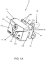
- FIGS. 1A-1C show apparatus 10 in the form of a sensing module for configuring on a vibrating machine or structure, such as pump or pump assembly 100.
- the sensing module 10 may include an outer shell 12 having a top surface 12a with a recessed portion in combination with a base 18, e.g., which may take the form of a printed circuit board 18a, having encapsulated electronics, e.g., such as elements 18b, 18c, 18d and 18f.
- the recessed portion is configured as, or formed with, an opening therein.
- the outer shell 12 also includes a circular rim 12b that is configured to form a mounting opening 12b' for receiving the mounting screw or fastener 16 to fasten the sensing module 10 to the vibrating machine or structure, such as the pump or pump assembly 100.
- the encapsulated electronics 18b, 18c, 18d and 18f includes a multicolored light array 18f (e.g., in the form of an LED array) that is arranged inside the outer shell 12, and configured to respond to signaling containing information about a condition being sensed and monitored by the sensing module 10 and provide along a projection axis at least one beam of light containing information about the condition.
- the signaling may be received from one or more of the other encapsulated electronics 18b, 18c, 18d, e.g., which may include an accelerometer, a temperature sensing device or other suitable sensing device that is either now known or later developed in the future.
- the sensing module 10 also includes a domed lens 14 configured in the recessed portion of the outer shell 12, that is configured to reflect, re-reflect and project the at least one beam of light outwardly in relation to the projection axis with a visibility of 360° about the sensing module 10 for viewing from afar, e.g., by an observer visually monitoring the sensing module 10.
- the domed lens 14 may include a middle lens portion 14a configured with a top curved surface and two side lens portions 14b, 14c configured with side surfaces.
- the middle lens portion 14a and two side lens portions 14b, 14c are transparent to project the at least one beam of light from the domed lens 14.
- the top curved surface may be configured with a suitable curvature for projecting, reflecting and re-reflecting the at least one beam of light.
- the visibility of the at least one beam of light being reflected, re-reflected and projected from the domed lens 14 may be defined visually either as being 360° in relation to a horizontal plane or as being 180° in relation to a vertical plane, when viewed by an observer in an industrial plant monitoring the vibrating machine or structure from a distance. In either case, the observer in the industrial plant monitoring the vibrating machine or structure may able to see the at least one beam of light being projected from the domed lens 14 from afar, e.g., with a glow of projected light.
- the sensing module 10 is shown to include a mounting screw or fastener 16, a power source 20, such as a lithium ion battery, as well as a stand-off mount 22 for configuring the sensing module 10 on the vibrating machine or structure, such as the pump or pump assembly 100.
- a clearance hole 18e may be formed in the base 18 for receiving the stand-off mount 22.
- a shortcoming of the above-described sensing module 10 is that it is fastened to the pump 100 or other equipment in a manner wherein the sensor module 10 may not be rigidly mounted to the pump 100 or other equipment in all six degrees of freedom.
- Typical mounting scenarios may include a flat surface against a flat surface, a flat surface against a curved surface or V-rails against a curved surface.
- the sensing module 10 may be attached to the pump 100 or other equipment in an over-constrained or under-constrained manner.
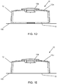
- FIG. 1D shows an example of an under-constrained design.
- FIG. 1E shows an example of an over-constraint design. Multiple mounting contacts are made between the base 18 of the sensing module and the pump 100, which also produces additional resonances degrading vibration measurement accuracy.
- An additional example of such a design can be found in applicant's U.S. Design Patent D747,225.
- the mounting bracket shown therein includes a nub, which provides a single point contact, and an edge, which provides a "line" with multiple points of contact.
- the present invention provides a new and unique apparatus for monitoring a vibrating machine or structure, such as a pump or pump assembly, having three mounting points on the apparatus for securely mounting the apparatus to the pump or pump assembly.
- the present invention increases the overall natural frequency of the apparatus' mounting to the vibrating machine, resulting in more accurate higher frequency measurement over a larger frequency band.
- the shortcomings of the art described above are overcome by providing an exact constraint method of utilizing a built-in three-point mount configuration.
- the three-point mount configuration provides the sensor module with a very rigid mount connection to virtually any surface condition, including flat, curved or irregular. All six degrees of freedom (X, Y, Z, theta-X, theta-Y and theta-Z) are properly constrained with this design approach, providing the best connection to the piece of equipment for vibration sensing and analysis.
- the three-point mount also provides an air barrier or gap between the sensing module and the equipment surface, allowing the sensor to be mounted to devices having a high surface temperature.
- the air gap acts as a thermal insulator for the sensor module, which can prevent premature sensor failure. This allows the sensor to be mounted onto hot running equipment, and in harsher environments.
- the apparatus may take the form of a sensing module for configuring on the vibrating machine or structure, such as the pump or pump assembly.
- a sensing module for configuring on a vibrating machine or structure, including a pump, is provided.
- the sensing module comprises a base comprising three mounting points configured to mount the sensing module to the vibrating machine or structure.
- the three mounting points comprise a first mounting projection providing a first mounting point, a second mounting projection providing a second mounting point, and a third mounting projection providing a third mounting point and comprising a rim surrounding an opening, wherein the opening is formed through a body of the sensing module and is configured to receive a fastener configured to secure the sensing module to the vibrating machine or structure.
- the first, second and third mounting projections are configured to constrain movement the sensing module in six degrees of freedom when the sensing module is mounted to the vibrating machine or structure.
- the first, second and third mounting projections are configured to form an air gap between the sensing module and the vibrating machine or structure when the sensing module is mounted to the vibrating machine or structure.
- the first mounting projection and the second mounting projection are rounded projections extending from the base.
- the first mounting projection and second mounting projection have substantially the same diameter.
- the first mounting projection and second mounting projection may also have substantially the same height projecting from the base.
- the base of the sensing module is substantially rectangular is shape, and the first and second mounting projections are positioned in separate corners of the base.
- the first and second mounting projections are positioned in separate corners along a same edge of the base, and the third mounting projection may be positioned in a location on the base of the sensing module so as to form a triangular set of mounting projections on the base of the sensing module.
- the first mounting projection, second mounting projection and third mounting projection are positioned on the base of the sensing module so as to form a set of mounting points on the base of the sensing module arranged in a triangle.
- the first mounting projection and the second mounting projection are positioned at extremities of the base of the sensing module.
- the first mounting projection and the second mounting projection may also be separated by approximately 120 degrees.
- the third mounting projection can be positioned at a centroid of the triangle formed by the first mounting projection, second mounting projection and third mounting projection.
- the first mounting projection and the second mounting projection are hemispherical projections extending from the base.
- the first mounting projection and the second mounting projection are molded into the base.
- the first mounting projection and the second mounting projection are secured to the base with a press fit, threading or an industrial adhesive.
- the base comprises one or more cavities formed therein.
- FIGS. 2A-2D The present invention will now be described with reference made to FIGS. 2A-2D .
- FIGS. 2A-2B show an apparatus 110 in the form of a sensing module for configuring on a vibrating machine or structure, such as pump or pump assembly 200.
- the sensing module 110 may include an outer shell 112 having a top surface 112a and a base 118, and encapsulated electronics.
- the encapsulated electronics may include, for example, a multicolored light array in the form of an LED array that is arranged inside the outer shell 112, and configured to respond to signaling containing information about a condition being sensed and monitored by the sensing module 110 and at least one beam of light containing information about the condition.
- the signaling may be received from one or more of the other encapsulated electronics, which may include an accelerometer, a temperature sensing device or other suitable sensing device that is either now known or later developed in the future.
- the sensing module 110 may also include a domed lens 114 configured on the outer shell 112, that is configured to reflect, re-reflect and project the at least one beam of light outwardly with a visibility of 360° about the sensing module 110 for viewing from afar, e.g., by an observer visually monitoring the sensing module 110.
- the outer shell 112 may also include a circular rim 112b that is configured to form a mounting opening 112b' for receiving a mounting screw or fastener to fasten the sensing module 110 to the vibrating machine or structure, such as the pump or pump assembly 200.
- the sensing module 110 may operate and function in the same manner as the sensing module 10 of FIG. 1A-1C described above and as described in U.S. Application Serial No. 14/685,134 filed on April 13, 2015 , which is incorporated by reference in its entirety.
- the sensing module 110 includes a unique mounting arrangement on the base 118 for mounting the sensing module 110 to a vibrating machine or structure, such as a pump 200, as shown for example in FIGS. 2B-2D .
- the base 118 comprises three mounting points in the form of three mounting projections 121, 122, 123.
- the base 118 of the sensing module 110 may include a first mounting projection 121 and a second mounting projection 122, which project from the base 118.
- the first mounting projection 121 and the second mounting projection 122 may be hemispherical in shape and may be substantially similar in size.
- the first and second mounting projections comprise a rounded shape, in order to create a true point contact to the mating surface, although other shapes may be utilized that create a contact point for the mating surface.
- the first mounting projection 121 and second mounting projection 122 are positioned in separate corners or extremities of the base 118.
- first mounting projection 121 and second mounting projection 122 are separated by an angle ⁇ of approximately 60 degrees, approximately 120 degrees or approximately 60 to 120 degrees.
- the first mounting projection 121 and second mounting projection 122 can be molded into the sensing module 110 as part of the base 118. This may be done for ease of manufacturability and cost.
- the first mounting projection 121 and/or second mounting projection 122 could also be separate parts that are secured in place to the base 118 via press-fit, threaded, industrial adhesive, or other attachment means.
- the base 118 also includes a third mounting projection 123 in the form of a rim 123 that surrounds the opening 112b' through the sensing module 110.
- the opening 112b' is configured to receive a fastener, such as a bolt or a screw, which may be received in a corresponding opening on the pump 200.
- the rim 123 may come into contact with the pump 200, as shown in FIG. 2D , separating the base 118 of the sensing module 110 from the surface of the pump 200.
- a force is applied to pre-load the sensing module 110 against its mount surface, such as the pump 200.
- the screw fastener (not shown) is provided for this purpose.
- the pre-load or mounting force lies within the triangle (represented by dashed lines 127 shown in FIG. 2B ) formed by the three points of contact 121, 122, 123, preferably at the centroid of the triangle 127.
- an air gap 126 is formed between the base 118 of the sensing module 110 and the surface of the pump 200 as a result of the three mounting points.
- the air gap 126 provides a thermal barrier between the sensing module 110 and the pump 200, which allows the sensing module 110 to function in high-temperature environments.
- one or more cavities 124, 125 may also be formed in the base 118 of the sensing module 110.
- the cavities 124, 125 reduce the thickness of the base 118 of the sensing module 110, which may be injection molded. Additionally, reducing the weight of the module without reducing its structural strength results in a higher natural frequency of the sensing module 110, and this can be achieved by incorporating cavities 124, 125 in the base 118.
Landscapes
- Engineering & Computer Science (AREA)
- Physics & Mathematics (AREA)
- General Physics & Mathematics (AREA)
- General Engineering & Computer Science (AREA)
- Mechanical Engineering (AREA)
- Measurement Of Mechanical Vibrations Or Ultrasonic Waves (AREA)
- Reciprocating Pumps (AREA)
- Geophysics And Detection Of Objects (AREA)
- Measuring Magnetic Variables (AREA)
- Vibration Prevention Devices (AREA)
Abstract
Description
- This application relates to a sensing module device for use in combination with a vibrating machine or structure that is configured to be securely mounted to the vibrating machine or structure.
- The present invention relates to an apparatus for monitoring a vibrating machine or structure, such as a pump or pump assembly. By way of example, such an apparatus may take form of a sensing module for configuring on the vibrating machine or structure, such as the pump or pump assembly. The sensing module may include an outer shell configured with a recessed portion, and a base having encapsulated electronics. An example of such a sensing module is shown and described in applicant's
U.S. Application No. 14/685,134 filed on April 13, 2015 - By way of example,
FIGS. 1A-1C showapparatus 10 in the form of a sensing module for configuring on a vibrating machine or structure, such as pump orpump assembly 100. Thesensing module 10 may include anouter shell 12 having atop surface 12a with a recessed portion in combination with abase 18, e.g., which may take the form of a printedcircuit board 18a, having encapsulated electronics, e.g., such aselements outer shell 12 also includes acircular rim 12b that is configured to form a mounting opening 12b' for receiving the mounting screw or fastener 16 to fasten thesensing module 10 to the vibrating machine or structure, such as the pump orpump assembly 100. - The
encapsulated electronics outer shell 12, and configured to respond to signaling containing information about a condition being sensed and monitored by thesensing module 10 and provide along a projection axis at least one beam of light containing information about the condition. By way of example, the signaling may be received from one or more of the other encapsulatedelectronics - The
sensing module 10 also includes adomed lens 14 configured in the recessed portion of theouter shell 12, that is configured to reflect, re-reflect and project the at least one beam of light outwardly in relation to the projection axis with a visibility of 360° about thesensing module 10 for viewing from afar, e.g., by an observer visually monitoring thesensing module 10. Thedomed lens 14 may include amiddle lens portion 14a configured with a top curved surface and twoside lens portions middle lens portion 14a and twoside lens portions domed lens 14. The top curved surface may be configured with a suitable curvature for projecting, reflecting and re-reflecting the at least one beam of light. - In effect, the visibility of the at least one beam of light being reflected, re-reflected and projected from the
domed lens 14 may be defined visually either as being 360° in relation to a horizontal plane or as being 180° in relation to a vertical plane, when viewed by an observer in an industrial plant monitoring the vibrating machine or structure from a distance. In either case, the observer in the industrial plant monitoring the vibrating machine or structure may able to see the at least one beam of light being projected from thedomed lens 14 from afar, e.g., with a glow of projected light. - In
FIG. 1A-1C , thesensing module 10 is shown to include a mounting screw orfastener 16, apower source 20, such as a lithium ion battery, as well as a stand-off mount 22 for configuring thesensing module 10 on the vibrating machine or structure, such as the pump orpump assembly 100. Aclearance hole 18e may be formed in thebase 18 for receiving the stand-offmount 22. - However, a shortcoming of the above-described
sensing module 10 is that it is fastened to thepump 100 or other equipment in a manner wherein thesensor module 10 may not be rigidly mounted to thepump 100 or other equipment in all six degrees of freedom. Typical mounting scenarios may include a flat surface against a flat surface, a flat surface against a curved surface or V-rails against a curved surface. - The
sensing module 10 may be attached to thepump 100 or other equipment in an over-constrained or under-constrained manner. -
FIG. 1D shows an example of an under-constrained design. A gap between theflat base 18 of thesensing module 10 and thepump 100, caused by a rim projecting from thebase 18, produces additional resonances, which degrade vibration measurement accuracy. -
FIG. 1E shows an example of an over-constraint design. Multiple mounting contacts are made between thebase 18 of the sensing module and thepump 100, which also produces additional resonances degrading vibration measurement accuracy. An additional example of such a design can be found in applicant's U.S. Design Patent D747,225. The mounting bracket shown therein includes a nub, which provides a single point contact, and an edge, which provides a "line" with multiple points of contact. - The present invention provides a new and unique apparatus for monitoring a vibrating machine or structure, such as a pump or pump assembly, having three mounting points on the apparatus for securely mounting the apparatus to the pump or pump assembly.
- The present invention increases the overall natural frequency of the apparatus' mounting to the vibrating machine, resulting in more accurate higher frequency measurement over a larger frequency band.
- The shortcomings of the art described above are overcome by providing an exact constraint method of utilizing a built-in three-point mount configuration. The three-point mount configuration provides the sensor module with a very rigid mount connection to virtually any surface condition, including flat, curved or irregular. All six degrees of freedom (X, Y, Z, theta-X, theta-Y and theta-Z) are properly constrained with this design approach, providing the best connection to the piece of equipment for vibration sensing and analysis.
- The three-point mount also provides an air barrier or gap between the sensing module and the equipment surface, allowing the sensor to be mounted to devices having a high surface temperature. The air gap acts as a thermal insulator for the sensor module, which can prevent premature sensor failure. This allows the sensor to be mounted onto hot running equipment, and in harsher environments.
- By way of example, the apparatus may take the form of a sensing module for configuring on the vibrating machine or structure, such as the pump or pump assembly.
- In accordance with a first aspect of the invention, a sensing module for configuring on a vibrating machine or structure, including a pump, is provided. The sensing module comprises a base comprising three mounting points configured to mount the sensing module to the vibrating machine or structure. The three mounting points comprise a first mounting projection providing a first mounting point, a second mounting projection providing a second mounting point, and a third mounting projection providing a third mounting point and comprising a rim surrounding an opening, wherein the opening is formed through a body of the sensing module and is configured to receive a fastener configured to secure the sensing module to the vibrating machine or structure.
- Further in accordance with the first aspect of the invention, the first, second and third mounting projections are configured to constrain movement the sensing module in six degrees of freedom when the sensing module is mounted to the vibrating machine or structure.
- In accordance with one or more embodiments of the sensing module of first aspect of the invention, the first, second and third mounting projections are configured to form an air gap between the sensing module and the vibrating machine or structure when the sensing module is mounted to the vibrating machine or structure.
- Further in accordance with one or more embodiments of the sensing module of first aspect of the invention, the first mounting projection and the second mounting projection are rounded projections extending from the base.
- Further in accordance with one or more embodiments of the sensing module of first aspect of the invention, the first mounting projection and second mounting projection have substantially the same diameter. The first mounting projection and second mounting projection may also have substantially the same height projecting from the base.
- Further in accordance with one or more embodiments of the sensing module of first aspect of the invention, the base of the sensing module is substantially rectangular is shape, and the first and second mounting projections are positioned in separate corners of the base. In one such embodiment, the first and second mounting projections are positioned in separate corners along a same edge of the base, and the third mounting projection may be positioned in a location on the base of the sensing module so as to form a triangular set of mounting projections on the base of the sensing module.
- Further in accordance with one or more embodiments of the sensing module of first aspect of the invention, the first mounting projection, second mounting projection and third mounting projection are positioned on the base of the sensing module so as to form a set of mounting points on the base of the sensing module arranged in a triangle. The first mounting projection and the second mounting projection are positioned at extremities of the base of the sensing module. The first mounting projection and the second mounting projection may also be separated by approximately 120 degrees. The third mounting projection can be positioned at a centroid of the triangle formed by the first mounting projection, second mounting projection and third mounting projection.
- Further in accordance with one or more embodiments of the sensing module of first aspect of the invention, the first mounting projection and the second mounting projection are hemispherical projections extending from the base.
- Further in accordance with one or more embodiments of the sensing module of first aspect of the invention, the first mounting projection and the second mounting projection are molded into the base.
- Further in accordance with one or more embodiments of the sensing module of first aspect of the invention, the first mounting projection and the second mounting projection are secured to the base with a press fit, threading or an industrial adhesive.
- Further in accordance with one or more embodiments of the sensing module of first aspect of the invention, the base comprises one or more cavities formed therein.
- The drawing includes the following Figures, which are not necessarily drawing to scale:
-
FIG. 1A is an exploded view of a sensing module, according to some embodiments of the present invention. -
FIG. 1B is a top perspective view of an outer shell of a sensing module, according to some embodiments of the present invention. -
FIG. 1C is a bottom perspective view of an outer shell of a sensing module, according to some embodiments of the present invention. -
FIG. 1D is a cross-sectional view of a sensing module mounted to a pump in an under-constrained manner. -
FIG. 1E is a cross-sectional view of a sensing module mounted to a pump in an over-constrained manner. -
FIG. 2A is a top perspective view of a sensing module according to a first embodiment of the present invention. -
FIG. 2B is a bottom perspective view of a sensing module according to the first embodiment of the present invention. -
FIG. 2C is view of a mounting projection on the base of a sensing module according to the first embodiment of the present invention. -
FIG. 2D is a side view of a sensing module according to the first embodiment of the present invention mounted to a pump. - The present invention will now be described with reference made to
FIGS. 2A-2D . - By way of example,
FIGS. 2A-2B show anapparatus 110 in the form of a sensing module for configuring on a vibrating machine or structure, such as pump or pumpassembly 200. Thesensing module 110 may include anouter shell 112 having atop surface 112a and abase 118, and encapsulated electronics. The encapsulated electronics may include, for example, a multicolored light array in the form of an LED array that is arranged inside theouter shell 112, and configured to respond to signaling containing information about a condition being sensed and monitored by thesensing module 110 and at least one beam of light containing information about the condition. By way of example, the signaling may be received from one or more of the other encapsulated electronics, which may include an accelerometer, a temperature sensing device or other suitable sensing device that is either now known or later developed in the future. Thesensing module 110 may also include adomed lens 114 configured on theouter shell 112, that is configured to reflect, re-reflect and project the at least one beam of light outwardly with a visibility of 360° about thesensing module 110 for viewing from afar, e.g., by an observer visually monitoring thesensing module 110. As a result, an observer in an industrial plant monitoring the vibrating machine or structure may able to see the at least one beam of light being projected from thedomed lens 114 from afar, e.g., with a glow of projected light. Theouter shell 112 may also include acircular rim 112b that is configured to form a mountingopening 112b' for receiving a mounting screw or fastener to fasten thesensing module 110 to the vibrating machine or structure, such as the pump or pumpassembly 200. - The
sensing module 110 may operate and function in the same manner as thesensing module 10 ofFIG. 1A-1C described above and as described inU.S. Application Serial No. 14/685,134 filed on April 13, 2015 - The
sensing module 110 includes a unique mounting arrangement on thebase 118 for mounting thesensing module 110 to a vibrating machine or structure, such as apump 200, as shown for example inFIGS. 2B-2D . Thebase 118 comprises three mounting points in the form of three mountingprojections - The
base 118 of thesensing module 110 may include afirst mounting projection 121 and asecond mounting projection 122, which project from thebase 118. Thefirst mounting projection 121 and thesecond mounting projection 122 may be hemispherical in shape and may be substantially similar in size. In a preferred embodiment, the first and second mounting projections comprise a rounded shape, in order to create a true point contact to the mating surface, although other shapes may be utilized that create a contact point for the mating surface. In the embodiment shown in the Figures, in which thebase 118 is substantially rectangular in shape, thefirst mounting projection 121 and second mountingprojection 122 are positioned in separate corners or extremities of thebase 118. In a preferred embodiment, thefirst mounting projection 121 and second mountingprojection 122 are separated by an angle Θ of approximately 60 degrees, approximately 120 degrees or approximately 60 to 120 degrees. Thefirst mounting projection 121 and second mountingprojection 122 can be molded into thesensing module 110 as part of thebase 118. This may be done for ease of manufacturability and cost. In alternative embodiments, thefirst mounting projection 121 and/or second mountingprojection 122 could also be separate parts that are secured in place to thebase 118 via press-fit, threaded, industrial adhesive, or other attachment means. - The base 118 also includes a
third mounting projection 123 in the form of arim 123 that surrounds theopening 112b' through thesensing module 110. Theopening 112b' is configured to receive a fastener, such as a bolt or a screw, which may be received in a corresponding opening on thepump 200. Therim 123 may come into contact with thepump 200, as shown inFIG. 2D , separating thebase 118 of thesensing module 110 from the surface of thepump 200. - A force is applied to pre-load the
sensing module 110 against its mount surface, such as thepump 200. The screw fastener (not shown) is provided for this purpose. The pre-load or mounting force lies within the triangle (represented by dashedlines 127 shown inFIG. 2B ) formed by the three points ofcontact triangle 127. - When the
sensing module 110 is secured to thepump 200, anair gap 126 is formed between the base 118 of thesensing module 110 and the surface of thepump 200 as a result of the three mounting points. Theair gap 126 provides a thermal barrier between thesensing module 110 and thepump 200, which allows thesensing module 110 to function in high-temperature environments. - As shown for example in
FIG. 2B , one ormore cavities base 118 of thesensing module 110. Thecavities base 118 of thesensing module 110, which may be injection molded. Additionally, reducing the weight of the module without reducing its structural strength results in a higher natural frequency of thesensing module 110, and this can be achieved by incorporatingcavities base 118. - It should be understood that, unless stated otherwise herein, any of the features, characteristics, alternatives or modifications described regarding a particular embodiment herein may also be applied, used, or incorporated with any other embodiment described herein. Also, the drawing herein is not drawn to scale.
- Although the invention has been described and illustrated with respect to exemplary embodiments thereof, the foregoing and various other additions and omissions may be made therein and thereto without departing from the spirit and scope of the present invention.
Claims (15)
- A sensing module (110) for configuring on a vibrating machine or structure, including a pump, comprising:
a base (118) comprising three mounting points (121, 122, 123) configured to mount the sensing module (110) to the vibrating machine or structure, wherein the three mounting points (121, 122, 123) comprise:a first mounting projection (121) providing a first mounting point;a second mounting projection (122) providing a second mounting point; anda third mounting projection (123) providing a third mounting point and comprising a rim (112b) surrounding an opening (112b'), wherein the opening (112b') is formed through a body of the sensing module (110) and is configured to receive a fastener configured to secure the sensing module (110) to the vibrating machine or structure. - The sensing module (110) of claim 1, wherein the first, second and third mounting projections (121, 122, 123) are configured to constrain movement the sensing module (110) in six degrees of freedom when the sensing module (110) is mounted to the vibrating machine or structure.
- The sensing module (110) of claim 1 or 2, wherein the first, second and third mounting projections (121, 122, 123) are configured to form an air gap (126) between the sensing module (110) and the vibrating machine or structure when the sensing module (110) is mounted to the vibrating machine or structure.
- The sensing module (110) of one of the preceding claims, wherein the first mounting projection (121) and the second mounting projection (122) are rounded projections extending from the base (118).
- The sensing module (110) of claim 4, wherein the first mounting projection (121) and second mounting projection (122) have substantially the same diameter.
- The sensing module (110) of claim 4, wherein the first mounting projection (121) and second mounting projection (122) have substantially the same height.
- The sensing module (110) of one of the preceding claims, wherein the base (118) of the sensing module (110) is substantially rectangular is shape, and the first and second mounting projections (121, 122) are positioned in separate corners of the base (118) along a same edge of the base (118).
- The sensing module (110) of claim 7, wherein the third mounting projection (123) is positioned in a location on the base (118) of the sensing module (110) so as to form a triangular set of mounting projections on the base (118) of the sensing module (110).
- The sensing module (110) of one of the preceding claims, wherein the first mounting projection (121), second mounting projection (122) and third mounting projection (123) are positioned on the base (118) of the sensing module (110) so as to form a set of mounting points on the base (118) of the sensing module (110) arranged in a triangle.
- The sensing module (110) of claim 9, wherein the first mounting projection (121) and the second mounting projection (123) are positioned at extremities of the base (118) of the sensing module (110).
- The sensing module (110) of claim 10, wherein the first mounting projection (121) and the second mounting projection (122) are separated by approximately 120 degrees.
- The sensing module (110) of claim 11, wherein the third mounting projection (123) is positioned at a centroid of the triangle formed by the first mounting projection (121), second mounting projection (122) and third mounting projection (123).
- The sensing module (110) of one of the preceding claims, wherein the first mounting projection (121) and the second mounting projection (122) are hemispherical projections extending from the base (118).
- The sensing module (110) of one of the preceding claims, wherein the first mounting projection (121) and the second mounting projection (122) are molded into the base (118) or are secured to the base (118) with a press fit, threading or an industrial adhesive.
- The sensing module (110) of one of the preceding claims, wherein the base (118) comprises one or more cavities (124, 125) formed therein.
Applications Claiming Priority (2)
| Application Number | Priority Date | Filing Date | Title |
|---|---|---|---|
| US15/483,302 US10422667B2 (en) | 2017-04-10 | 2017-04-10 | Three point mount for a vibration sensing apparatus |
| US15/837,443 US20190178689A1 (en) | 2017-12-11 | 2017-12-11 | Exact Constraint Magnetic Mount for Vibration Sensing Module |
Publications (2)
| Publication Number | Publication Date |
|---|---|
| EP3388797A1 true EP3388797A1 (en) | 2018-10-17 |
| EP3388797B1 EP3388797B1 (en) | 2022-11-16 |
Family
ID=61837670
Family Applications (2)
| Application Number | Title | Priority Date | Filing Date |
|---|---|---|---|
| EP18164920.3A Withdrawn EP3388798A1 (en) | 2017-04-10 | 2018-03-29 | Exact constraint magnetic mount for vibration sensing module |
| EP18164918.7A Active EP3388797B1 (en) | 2017-04-10 | 2018-03-29 | Exact constraint three-point vibration sensing module |
Family Applications Before (1)
| Application Number | Title | Priority Date | Filing Date |
|---|---|---|---|
| EP18164920.3A Withdrawn EP3388798A1 (en) | 2017-04-10 | 2018-03-29 | Exact constraint magnetic mount for vibration sensing module |
Country Status (5)
| Country | Link |
|---|---|
| EP (2) | EP3388798A1 (en) |
| CN (2) | CN108691761A (en) |
| BR (2) | BR102018006967B1 (en) |
| CA (2) | CA3000485A1 (en) |
| MX (3) | MX2018004346A (en) |
Cited By (3)
| Publication number | Priority date | Publication date | Assignee | Title |
|---|---|---|---|---|
| CN116517840A (en) * | 2023-05-10 | 2023-08-01 | 潜江市昌贵水产食品股份有限公司 | Screw compressor, conveying refrigeration mechanism and crayfish processing method |
| CN117967920A (en) * | 2024-01-12 | 2024-05-03 | 埃夫特智能装备股份有限公司 | A sensor fixing device convenient for vibration testing |
| WO2024130880A1 (en) * | 2022-12-23 | 2024-06-27 | 安徽和佳医疗用品科技有限公司 | Glove mold temperature monitor for pvc glove production line |
Families Citing this family (4)
| Publication number | Priority date | Publication date | Assignee | Title |
|---|---|---|---|---|
| CN113029439B (en) * | 2019-12-24 | 2022-07-12 | 苏州宝时得电动工具有限公司 | Motor rotor balance detection device and motor rotor balance detection method and equipment |
| EP4189332B1 (en) | 2020-07-30 | 2024-12-04 | Cornell Pump Company LLC | Magnetic adaptor for machine monitoring device |
| MX2023003069A (en) | 2020-09-25 | 2023-04-12 | Cornell Pump Company LLC | Mounting pocket for remote equipment monitoring device. |
| CN121630705B (en) * | 2026-02-03 | 2026-04-21 | 聚变新能(安徽)有限公司 | Method and device for testing cryopump, electronic device and storage medium |
Citations (3)
| Publication number | Priority date | Publication date | Assignee | Title |
|---|---|---|---|---|
| GB1319055A (en) * | 1969-05-28 | 1973-05-31 | Ransome Hoffmann Pollard | Vibration transducer mounting arrangement |
| WO2003040780A2 (en) * | 2001-11-08 | 2003-05-15 | Massachusetts Institute Of Technology | Multiple degree of freedom compliant mechanism |
| US20150355216A1 (en) * | 2014-06-10 | 2015-12-10 | Uptime Solutions, Inc. | Vibration-sensing field unit |
Family Cites Families (10)
| Publication number | Priority date | Publication date | Assignee | Title |
|---|---|---|---|---|
| US6598479B1 (en) * | 2001-11-19 | 2003-07-29 | Csi Technology, Inc. | Integral magnet vibration sensor |
| JP5257888B2 (en) * | 2008-07-25 | 2013-08-07 | サミー株式会社 | Game machine |
| DE102009045557A1 (en) * | 2009-10-12 | 2011-04-14 | Robert Bosch Gmbh | Mounting arrangement for a sensor arrangement and sensor arrangement |
| CN202119352U (en) * | 2011-05-23 | 2012-01-18 | 北京首钢建设集团有限公司 | Multifunctional adjusting rack |
| WO2013183302A1 (en) * | 2012-06-08 | 2013-12-12 | パナソニック株式会社 | Acoustooptic imaging device |
| DE102014205612B4 (en) * | 2014-03-26 | 2020-07-09 | Bayerische Motoren Werke Aktiengesellschaft | Method for positioning a component |
| CN205098088U (en) * | 2015-02-15 | 2016-03-23 | 特迈驰公司 | Magnetism binding clip and including its vehicle |
| US9811984B2 (en) | 2015-04-13 | 2017-11-07 | Itt Manufacturing Enterprises Llc | Sensing module for monitoring conditions of a pump or pump assembly |
| GB2542382A (en) * | 2015-09-17 | 2017-03-22 | Gp Acoustics (Uk) Ltd | Low-profile loudspeaker |
| CN105708448A (en) * | 2016-05-04 | 2016-06-29 | 深圳诺康医疗设备股份有限公司 | Information acquisition device |
-
2018
- 2018-03-29 EP EP18164920.3A patent/EP3388798A1/en not_active Withdrawn
- 2018-03-29 EP EP18164918.7A patent/EP3388797B1/en active Active
- 2018-04-06 BR BR102018006967-5A patent/BR102018006967B1/en active IP Right Grant
- 2018-04-09 MX MX2018004346A patent/MX2018004346A/en unknown
- 2018-04-09 BR BR102018007114-9A patent/BR102018007114A2/en not_active Application Discontinuation
- 2018-04-09 CA CA3000485A patent/CA3000485A1/en active Pending
- 2018-04-09 CA CA3000488A patent/CA3000488A1/en active Pending
- 2018-04-09 MX MX2018004345A patent/MX385448B/en unknown
- 2018-04-09 MX MX2021009758A patent/MX2021009758A/en unknown
- 2018-04-10 CN CN201810315458.4A patent/CN108691761A/en active Pending
- 2018-04-10 CN CN201810315967.7A patent/CN108692162A/en active Pending
Patent Citations (3)
| Publication number | Priority date | Publication date | Assignee | Title |
|---|---|---|---|---|
| GB1319055A (en) * | 1969-05-28 | 1973-05-31 | Ransome Hoffmann Pollard | Vibration transducer mounting arrangement |
| WO2003040780A2 (en) * | 2001-11-08 | 2003-05-15 | Massachusetts Institute Of Technology | Multiple degree of freedom compliant mechanism |
| US20150355216A1 (en) * | 2014-06-10 | 2015-12-10 | Uptime Solutions, Inc. | Vibration-sensing field unit |
Cited By (4)
| Publication number | Priority date | Publication date | Assignee | Title |
|---|---|---|---|---|
| WO2024130880A1 (en) * | 2022-12-23 | 2024-06-27 | 安徽和佳医疗用品科技有限公司 | Glove mold temperature monitor for pvc glove production line |
| CN116517840A (en) * | 2023-05-10 | 2023-08-01 | 潜江市昌贵水产食品股份有限公司 | Screw compressor, conveying refrigeration mechanism and crayfish processing method |
| CN116517840B (en) * | 2023-05-10 | 2023-11-21 | 潜江市昌贵水产食品股份有限公司 | Screw compressor, conveying refrigeration mechanism and crayfish processing method |
| CN117967920A (en) * | 2024-01-12 | 2024-05-03 | 埃夫特智能装备股份有限公司 | A sensor fixing device convenient for vibration testing |
Also Published As
| Publication number | Publication date |
|---|---|
| MX2021009758A (en) | 2022-11-08 |
| MX2018004345A (en) | 2018-11-09 |
| BR102018007114A2 (en) | 2019-02-26 |
| MX2018004346A (en) | 2018-11-09 |
| EP3388797B1 (en) | 2022-11-16 |
| BR102018006967A2 (en) | 2018-12-04 |
| CA3000488A1 (en) | 2018-10-10 |
| EP3388798A1 (en) | 2018-10-17 |
| MX385448B (en) | 2025-03-18 |
| CN108692162A (en) | 2018-10-23 |
| CN108691761A (en) | 2018-10-23 |
| CA3000485A1 (en) | 2018-10-10 |
| BR102018006967B1 (en) | 2023-11-14 |
Similar Documents
| Publication | Publication Date | Title |
|---|---|---|
| EP3388797B1 (en) | Exact constraint three-point vibration sensing module | |
| US10422667B2 (en) | Three point mount for a vibration sensing apparatus | |
| US20070284512A1 (en) | External force detecting device | |
| US20250362571A1 (en) | Imaging device including an imaging element, a mount, and members | |
| CA2979610C (en) | Sensing module for monitoring conditions of a pump or pump assembly | |
| US20100128245A1 (en) | Distance measurement device | |
| EP3270254B1 (en) | Angle sensing and measurement apparatus and tripod head employing the same | |
| CN205594181U (en) | Marine gravimeter stabilized platform's frame set spare | |
| US11131577B2 (en) | Three point mount for a vibration sensing apparatus | |
| US20190178689A1 (en) | Exact Constraint Magnetic Mount for Vibration Sensing Module | |
| US11255717B2 (en) | Vibration detecting arrangement for reducing resonant noise | |
| US10573158B2 (en) | Radio equipment | |
| CN116506718B (en) | Camera | |
| US11690186B2 (en) | Panel module unit | |
| US4107545A (en) | Mounting construction for motion sensor | |
| JPS6085311A (en) | Slant detecting switch | |
| US6034613A (en) | Shock and vibration sensor | |
| CN108413270A (en) | Flashlight | |
| CN116528034B (en) | Video camera for elevator scene | |
| CN210603218U (en) | Three-dimensional laser scanning camera, laser instrument fixing device | |
| CN120593741A (en) | A MEMS inertial measurement combination for large shock and vibration reduction | |
| JP2021173622A (en) | Inertial measurement device | |
| CN112822344A (en) | Instrument monitoring camera device | |
| JP2004240145A (en) | Optical axis adjustment method for camera of imaging apparatus | |
| JP2019190899A (en) | Vibration detector |
Legal Events
| Date | Code | Title | Description |
|---|---|---|---|
| PUAI | Public reference made under article 153(3) epc to a published international application that has entered the european phase |
Free format text: ORIGINAL CODE: 0009012 |
|
| STAA | Information on the status of an ep patent application or granted ep patent |
Free format text: STATUS: THE APPLICATION HAS BEEN PUBLISHED |
|
| AK | Designated contracting states |
Kind code of ref document: A1 Designated state(s): AL AT BE BG CH CY CZ DE DK EE ES FI FR GB GR HR HU IE IS IT LI LT LU LV MC MK MT NL NO PL PT RO RS SE SI SK SM TR |
|
| AX | Request for extension of the european patent |
Extension state: BA ME |
|
| STAA | Information on the status of an ep patent application or granted ep patent |
Free format text: STATUS: REQUEST FOR EXAMINATION WAS MADE |
|
| 17P | Request for examination filed |
Effective date: 20190417 |
|
| RBV | Designated contracting states (corrected) |
Designated state(s): AL AT BE BG CH CY CZ DE DK EE ES FI FR GB GR HR HU IE IS IT LI LT LU LV MC MK MT NL NO PL PT RO RS SE SI SK SM TR |
|
| RIN1 | Information on inventor provided before grant (corrected) |
Inventor name: PLAYFORD, MARK Inventor name: DECOOK, BRADLEY |
|
| STAA | Information on the status of an ep patent application or granted ep patent |
Free format text: STATUS: EXAMINATION IS IN PROGRESS |
|
| 17Q | First examination report despatched |
Effective date: 20200925 |
|
| GRAP | Despatch of communication of intention to grant a patent |
Free format text: ORIGINAL CODE: EPIDOSNIGR1 |
|
| STAA | Information on the status of an ep patent application or granted ep patent |
Free format text: STATUS: GRANT OF PATENT IS INTENDED |
|
| RIC1 | Information provided on ipc code assigned before grant |
Ipc: G01M 13/00 20060101ALI20220516BHEP Ipc: G01H 1/00 20060101AFI20220516BHEP |
|
| INTG | Intention to grant announced |
Effective date: 20220608 |
|
| GRAS | Grant fee paid |
Free format text: ORIGINAL CODE: EPIDOSNIGR3 |
|
| GRAA | (expected) grant |
Free format text: ORIGINAL CODE: 0009210 |
|
| STAA | Information on the status of an ep patent application or granted ep patent |
Free format text: STATUS: THE PATENT HAS BEEN GRANTED |
|
| AK | Designated contracting states |
Kind code of ref document: B1 Designated state(s): AL AT BE BG CH CY CZ DE DK EE ES FI FR GB GR HR HU IE IS IT LI LT LU LV MC MK MT NL NO PL PT RO RS SE SI SK SM TR |
|
| REG | Reference to a national code |
Ref country code: GB Ref legal event code: FG4D |
|
| REG | Reference to a national code |
Ref country code: CH Ref legal event code: EP |
|
| REG | Reference to a national code |
Ref country code: DE Ref legal event code: R096 Ref document number: 602018043040 Country of ref document: DE |
|
| REG | Reference to a national code |
Ref country code: IE Ref legal event code: FG4D |
|
| REG | Reference to a national code |
Ref country code: AT Ref legal event code: REF Ref document number: 1532020 Country of ref document: AT Kind code of ref document: T Effective date: 20221215 |
|
| REG | Reference to a national code |
Ref country code: LT Ref legal event code: MG9D |
|
| REG | Reference to a national code |
Ref country code: GR Ref legal event code: EP Ref document number: 20230400257 Country of ref document: GR Effective date: 20230307 |
|
| REG | Reference to a national code |
Ref country code: NL Ref legal event code: MP Effective date: 20221116 |
|
| REG | Reference to a national code |
Ref country code: NO Ref legal event code: T2 Effective date: 20221116 |
|
| REG | Reference to a national code |
Ref country code: AT Ref legal event code: MK05 Ref document number: 1532020 Country of ref document: AT Kind code of ref document: T Effective date: 20221116 |
|
| PG25 | Lapsed in a contracting state [announced via postgrant information from national office to epo] |
Ref country code: SE Free format text: LAPSE BECAUSE OF FAILURE TO SUBMIT A TRANSLATION OF THE DESCRIPTION OR TO PAY THE FEE WITHIN THE PRESCRIBED TIME-LIMIT Effective date: 20221116 Ref country code: PT Free format text: LAPSE BECAUSE OF FAILURE TO SUBMIT A TRANSLATION OF THE DESCRIPTION OR TO PAY THE FEE WITHIN THE PRESCRIBED TIME-LIMIT Effective date: 20230316 Ref country code: LT Free format text: LAPSE BECAUSE OF FAILURE TO SUBMIT A TRANSLATION OF THE DESCRIPTION OR TO PAY THE FEE WITHIN THE PRESCRIBED TIME-LIMIT Effective date: 20221116 Ref country code: FI Free format text: LAPSE BECAUSE OF FAILURE TO SUBMIT A TRANSLATION OF THE DESCRIPTION OR TO PAY THE FEE WITHIN THE PRESCRIBED TIME-LIMIT Effective date: 20221116 Ref country code: ES Free format text: LAPSE BECAUSE OF FAILURE TO SUBMIT A TRANSLATION OF THE DESCRIPTION OR TO PAY THE FEE WITHIN THE PRESCRIBED TIME-LIMIT Effective date: 20221116 Ref country code: AT Free format text: LAPSE BECAUSE OF FAILURE TO SUBMIT A TRANSLATION OF THE DESCRIPTION OR TO PAY THE FEE WITHIN THE PRESCRIBED TIME-LIMIT Effective date: 20221116 |
|
| PG25 | Lapsed in a contracting state [announced via postgrant information from national office to epo] |
Ref country code: RS Free format text: LAPSE BECAUSE OF FAILURE TO SUBMIT A TRANSLATION OF THE DESCRIPTION OR TO PAY THE FEE WITHIN THE PRESCRIBED TIME-LIMIT Effective date: 20221116 Ref country code: PL Free format text: LAPSE BECAUSE OF FAILURE TO SUBMIT A TRANSLATION OF THE DESCRIPTION OR TO PAY THE FEE WITHIN THE PRESCRIBED TIME-LIMIT Effective date: 20221116 Ref country code: LV Free format text: LAPSE BECAUSE OF FAILURE TO SUBMIT A TRANSLATION OF THE DESCRIPTION OR TO PAY THE FEE WITHIN THE PRESCRIBED TIME-LIMIT Effective date: 20221116 Ref country code: IS Free format text: LAPSE BECAUSE OF FAILURE TO SUBMIT A TRANSLATION OF THE DESCRIPTION OR TO PAY THE FEE WITHIN THE PRESCRIBED TIME-LIMIT Effective date: 20230316 Ref country code: HR Free format text: LAPSE BECAUSE OF FAILURE TO SUBMIT A TRANSLATION OF THE DESCRIPTION OR TO PAY THE FEE WITHIN THE PRESCRIBED TIME-LIMIT Effective date: 20221116 |
|
| PG25 | Lapsed in a contracting state [announced via postgrant information from national office to epo] |
Ref country code: NL Free format text: LAPSE BECAUSE OF FAILURE TO SUBMIT A TRANSLATION OF THE DESCRIPTION OR TO PAY THE FEE WITHIN THE PRESCRIBED TIME-LIMIT Effective date: 20221116 |
|
| P01 | Opt-out of the competence of the unified patent court (upc) registered |
Effective date: 20230528 |
|
| PG25 | Lapsed in a contracting state [announced via postgrant information from national office to epo] |
Ref country code: SM Free format text: LAPSE BECAUSE OF FAILURE TO SUBMIT A TRANSLATION OF THE DESCRIPTION OR TO PAY THE FEE WITHIN THE PRESCRIBED TIME-LIMIT Effective date: 20221116 Ref country code: RO Free format text: LAPSE BECAUSE OF FAILURE TO SUBMIT A TRANSLATION OF THE DESCRIPTION OR TO PAY THE FEE WITHIN THE PRESCRIBED TIME-LIMIT Effective date: 20221116 Ref country code: EE Free format text: LAPSE BECAUSE OF FAILURE TO SUBMIT A TRANSLATION OF THE DESCRIPTION OR TO PAY THE FEE WITHIN THE PRESCRIBED TIME-LIMIT Effective date: 20221116 Ref country code: DK Free format text: LAPSE BECAUSE OF FAILURE TO SUBMIT A TRANSLATION OF THE DESCRIPTION OR TO PAY THE FEE WITHIN THE PRESCRIBED TIME-LIMIT Effective date: 20221116 Ref country code: CZ Free format text: LAPSE BECAUSE OF FAILURE TO SUBMIT A TRANSLATION OF THE DESCRIPTION OR TO PAY THE FEE WITHIN THE PRESCRIBED TIME-LIMIT Effective date: 20221116 |
|
| REG | Reference to a national code |
Ref country code: DE Ref legal event code: R097 Ref document number: 602018043040 Country of ref document: DE |
|
| PG25 | Lapsed in a contracting state [announced via postgrant information from national office to epo] |
Ref country code: SK Free format text: LAPSE BECAUSE OF FAILURE TO SUBMIT A TRANSLATION OF THE DESCRIPTION OR TO PAY THE FEE WITHIN THE PRESCRIBED TIME-LIMIT Effective date: 20221116 Ref country code: AL Free format text: LAPSE BECAUSE OF FAILURE TO SUBMIT A TRANSLATION OF THE DESCRIPTION OR TO PAY THE FEE WITHIN THE PRESCRIBED TIME-LIMIT Effective date: 20221116 |
|
| PLBE | No opposition filed within time limit |
Free format text: ORIGINAL CODE: 0009261 |
|
| STAA | Information on the status of an ep patent application or granted ep patent |
Free format text: STATUS: NO OPPOSITION FILED WITHIN TIME LIMIT |
|
| 26N | No opposition filed |
Effective date: 20230817 |
|
| PG25 | Lapsed in a contracting state [announced via postgrant information from national office to epo] |
Ref country code: MC Free format text: LAPSE BECAUSE OF FAILURE TO SUBMIT A TRANSLATION OF THE DESCRIPTION OR TO PAY THE FEE WITHIN THE PRESCRIBED TIME-LIMIT Effective date: 20221116 |
|
| REG | Reference to a national code |
Ref country code: CH Ref legal event code: PL |
|
| PG25 | Lapsed in a contracting state [announced via postgrant information from national office to epo] |
Ref country code: SI Free format text: LAPSE BECAUSE OF FAILURE TO SUBMIT A TRANSLATION OF THE DESCRIPTION OR TO PAY THE FEE WITHIN THE PRESCRIBED TIME-LIMIT Effective date: 20221116 |
|
| REG | Reference to a national code |
Ref country code: BE Ref legal event code: MM Effective date: 20230331 |
|
| PG25 | Lapsed in a contracting state [announced via postgrant information from national office to epo] |
Ref country code: LU Free format text: LAPSE BECAUSE OF NON-PAYMENT OF DUE FEES Effective date: 20230329 |
|
| PG25 | Lapsed in a contracting state [announced via postgrant information from national office to epo] |
Ref country code: LI Free format text: LAPSE BECAUSE OF NON-PAYMENT OF DUE FEES Effective date: 20230331 Ref country code: CH Free format text: LAPSE BECAUSE OF NON-PAYMENT OF DUE FEES Effective date: 20230331 |
|
| PG25 | Lapsed in a contracting state [announced via postgrant information from national office to epo] |
Ref country code: BE Free format text: LAPSE BECAUSE OF NON-PAYMENT OF DUE FEES Effective date: 20230331 |
|
| PG25 | Lapsed in a contracting state [announced via postgrant information from national office to epo] |
Ref country code: IT Free format text: LAPSE BECAUSE OF FAILURE TO SUBMIT A TRANSLATION OF THE DESCRIPTION OR TO PAY THE FEE WITHIN THE PRESCRIBED TIME-LIMIT Effective date: 20221116 |
|
| PG25 | Lapsed in a contracting state [announced via postgrant information from national office to epo] |
Ref country code: BG Free format text: LAPSE BECAUSE OF FAILURE TO SUBMIT A TRANSLATION OF THE DESCRIPTION OR TO PAY THE FEE WITHIN THE PRESCRIBED TIME-LIMIT Effective date: 20221116 |
|
| PG25 | Lapsed in a contracting state [announced via postgrant information from national office to epo] |
Ref country code: BG Free format text: LAPSE BECAUSE OF FAILURE TO SUBMIT A TRANSLATION OF THE DESCRIPTION OR TO PAY THE FEE WITHIN THE PRESCRIBED TIME-LIMIT Effective date: 20221116 |
|
| PGFP | Annual fee paid to national office [announced via postgrant information from national office to epo] |
Ref country code: DE Payment date: 20250218 Year of fee payment: 8 |
|
| PGFP | Annual fee paid to national office [announced via postgrant information from national office to epo] |
Ref country code: IE Payment date: 20250220 Year of fee payment: 8 |
|
| PGFP | Annual fee paid to national office [announced via postgrant information from national office to epo] |
Ref country code: NO Payment date: 20250219 Year of fee payment: 8 |
|
| PGFP | Annual fee paid to national office [announced via postgrant information from national office to epo] |
Ref country code: GR Payment date: 20250220 Year of fee payment: 8 |
|
| PGFP | Annual fee paid to national office [announced via postgrant information from national office to epo] |
Ref country code: FR Payment date: 20250218 Year of fee payment: 8 |
|
| PGFP | Annual fee paid to national office [announced via postgrant information from national office to epo] |
Ref country code: GB Payment date: 20250221 Year of fee payment: 8 |
|
| PG25 | Lapsed in a contracting state [announced via postgrant information from national office to epo] |
Ref country code: CY Free format text: LAPSE BECAUSE OF FAILURE TO SUBMIT A TRANSLATION OF THE DESCRIPTION OR TO PAY THE FEE WITHIN THE PRESCRIBED TIME-LIMIT; INVALID AB INITIO Effective date: 20180329 |
|
| PG25 | Lapsed in a contracting state [announced via postgrant information from national office to epo] |
Ref country code: HU Free format text: LAPSE BECAUSE OF FAILURE TO SUBMIT A TRANSLATION OF THE DESCRIPTION OR TO PAY THE FEE WITHIN THE PRESCRIBED TIME-LIMIT; INVALID AB INITIO Effective date: 20180329 |
|
| PG25 | Lapsed in a contracting state [announced via postgrant information from national office to epo] |
Ref country code: TR Free format text: LAPSE BECAUSE OF FAILURE TO SUBMIT A TRANSLATION OF THE DESCRIPTION OR TO PAY THE FEE WITHIN THE PRESCRIBED TIME-LIMIT Effective date: 20221116 |