EP3388764A1 - Cooling appliance - Google Patents
Cooling appliance Download PDFInfo
- Publication number
- EP3388764A1 EP3388764A1 EP18164267.9A EP18164267A EP3388764A1 EP 3388764 A1 EP3388764 A1 EP 3388764A1 EP 18164267 A EP18164267 A EP 18164267A EP 3388764 A1 EP3388764 A1 EP 3388764A1
- Authority
- EP
- European Patent Office
- Prior art keywords
- accommodating space
- gap
- refrigeration appliance
- support shaft
- cover plate
- Prior art date
- Legal status (The legal status is an assumption and is not a legal conclusion. Google has not performed a legal analysis and makes no representation as to the accuracy of the status listed.)
- Withdrawn
Links
- 238000001816 cooling Methods 0.000 title 1
- 238000005057 refrigeration Methods 0.000 claims abstract description 41
- 230000000712 assembly Effects 0.000 claims abstract description 6
- 238000000429 assembly Methods 0.000 claims abstract description 6
- 210000000078 claw Anatomy 0.000 claims description 13
- 238000010586 diagram Methods 0.000 description 6
- 238000009434 installation Methods 0.000 description 4
- 238000000034 method Methods 0.000 description 4
- 230000008569 process Effects 0.000 description 4
- 230000000903 blocking effect Effects 0.000 description 2
- 230000002708 enhancing effect Effects 0.000 description 2
- 230000002452 interceptive effect Effects 0.000 description 2
- 238000000926 separation method Methods 0.000 description 2
- 230000004075 alteration Effects 0.000 description 1
- 230000004888 barrier function Effects 0.000 description 1
- 230000000694 effects Effects 0.000 description 1
- 230000005489 elastic deformation Effects 0.000 description 1
- 239000006260 foam Substances 0.000 description 1
- 230000000670 limiting effect Effects 0.000 description 1
- 230000007774 longterm Effects 0.000 description 1
- 239000000463 material Substances 0.000 description 1
- 230000004048 modification Effects 0.000 description 1
- 238000012986 modification Methods 0.000 description 1
Images



Classifications
-
- F—MECHANICAL ENGINEERING; LIGHTING; HEATING; WEAPONS; BLASTING
- F25—REFRIGERATION OR COOLING; COMBINED HEATING AND REFRIGERATION SYSTEMS; HEAT PUMP SYSTEMS; MANUFACTURE OR STORAGE OF ICE; LIQUEFACTION SOLIDIFICATION OF GASES
- F25D—REFRIGERATORS; COLD ROOMS; ICE-BOXES; COOLING OR FREEZING APPARATUS NOT OTHERWISE PROVIDED FOR
- F25D23/00—General constructional features
- F25D23/02—Doors; Covers
- F25D23/025—Secondary closures
-
- E—FIXED CONSTRUCTIONS
- E05—LOCKS; KEYS; WINDOW OR DOOR FITTINGS; SAFES
- E05D—HINGES OR SUSPENSION DEVICES FOR DOORS, WINDOWS OR WINGS
- E05D7/00—Hinges or pivots of special construction
- E05D7/10—Hinges or pivots of special construction to allow easy separation or connection of the parts at the hinge axis
- E05D7/1061—Hinges or pivots of special construction to allow easy separation or connection of the parts at the hinge axis in a radial direction
-
- E—FIXED CONSTRUCTIONS
- E05—LOCKS; KEYS; WINDOW OR DOOR FITTINGS; SAFES
- E05D—HINGES OR SUSPENSION DEVICES FOR DOORS, WINDOWS OR WINGS
- E05D7/00—Hinges or pivots of special construction
- E05D7/10—Hinges or pivots of special construction to allow easy separation or connection of the parts at the hinge axis
- E05D7/1061—Hinges or pivots of special construction to allow easy separation or connection of the parts at the hinge axis in a radial direction
- E05D7/1066—Hinges or pivots of special construction to allow easy separation or connection of the parts at the hinge axis in a radial direction requiring a specific angular position
- E05D7/1072—Hinges or pivots of special construction to allow easy separation or connection of the parts at the hinge axis in a radial direction requiring a specific angular position the pin having a non-circular cross-section
-
- E—FIXED CONSTRUCTIONS
- E05—LOCKS; KEYS; WINDOW OR DOOR FITTINGS; SAFES
- E05D—HINGES OR SUSPENSION DEVICES FOR DOORS, WINDOWS OR WINGS
- E05D7/00—Hinges or pivots of special construction
- E05D7/10—Hinges or pivots of special construction to allow easy separation or connection of the parts at the hinge axis
- E05D7/1061—Hinges or pivots of special construction to allow easy separation or connection of the parts at the hinge axis in a radial direction
- E05D7/1077—Hinges or pivots of special construction to allow easy separation or connection of the parts at the hinge axis in a radial direction with snap-fitted pins
-
- E—FIXED CONSTRUCTIONS
- E05—LOCKS; KEYS; WINDOW OR DOOR FITTINGS; SAFES
- E05Y—INDEXING SCHEME ASSOCIATED WITH SUBCLASSES E05D AND E05F, RELATING TO CONSTRUCTION ELEMENTS, ELECTRIC CONTROL, POWER SUPPLY, POWER SIGNAL OR TRANSMISSION, USER INTERFACES, MOUNTING OR COUPLING, DETAILS, ACCESSORIES, AUXILIARY OPERATIONS NOT OTHERWISE PROVIDED FOR, APPLICATION THEREOF
- E05Y2600/00—Mounting or coupling arrangements for elements provided for in this subclass
- E05Y2600/60—Mounting or coupling members; Accessories therefor
- E05Y2600/63—Retainers
-
- E—FIXED CONSTRUCTIONS
- E05—LOCKS; KEYS; WINDOW OR DOOR FITTINGS; SAFES
- E05Y—INDEXING SCHEME ASSOCIATED WITH SUBCLASSES E05D AND E05F, RELATING TO CONSTRUCTION ELEMENTS, ELECTRIC CONTROL, POWER SUPPLY, POWER SIGNAL OR TRANSMISSION, USER INTERFACES, MOUNTING OR COUPLING, DETAILS, ACCESSORIES, AUXILIARY OPERATIONS NOT OTHERWISE PROVIDED FOR, APPLICATION THEREOF
- E05Y2900/00—Application of doors, windows, wings or fittings thereof
- E05Y2900/30—Application of doors, windows, wings or fittings thereof for domestic appliances
- E05Y2900/31—Application of doors, windows, wings or fittings thereof for domestic appliances for refrigerators
-
- F—MECHANICAL ENGINEERING; LIGHTING; HEATING; WEAPONS; BLASTING
- F25—REFRIGERATION OR COOLING; COMBINED HEATING AND REFRIGERATION SYSTEMS; HEAT PUMP SYSTEMS; MANUFACTURE OR STORAGE OF ICE; LIQUEFACTION SOLIDIFICATION OF GASES
- F25D—REFRIGERATORS; COLD ROOMS; ICE-BOXES; COOLING OR FREEZING APPARATUS NOT OTHERWISE PROVIDED FOR
- F25D2323/00—General constructional features not provided for in other groups of this subclass
- F25D2323/02—Details of doors or covers not otherwise covered
- F25D2323/024—Door hinges
Definitions
- the present application relates to a refrigeration appliance, such as a refrigerator.
- a type of conventional refrigeration appliance such as a refrigerator, comprises a storage chamber, shelves arranged in the storage chamber, and a turnable cover plate arranged at the position of the opening of the storage chamber, and the cover plate can be turned between a horizontal position and a vertical position, and can cover the shelves and articles thereon at the vertical position.
- support parts are first mounted on two side walls of the cover plate, the support parts are provided with support shafts, the support shafts pass through accommodating spaces arranged in the cover plate, such as slots or holes, the support parts are then fixed on the side walls of the storage chamber, and thereby the cover plate can rotate around the support shafts.
- the support parts have to be mounted on the side walls of the storage chamber in advance.
- the support parts are fixed in a foam layer between a shell and a liner of the refrigeration appliance in advance, and pass through the side walls of the storage chamber to extend into the storage chamber, so the support parts must be assembled on the refrigeration appliance first.
- the support shafts which correspond to the positions of the two side walls are axially projected into the storage chamber, so that the support shafts cannot be directly inserted into the accommodating spaces along an axial direction, and as a result, a barrier is created to the installation of the cover plate.
- One objective of the present application is to provide a refrigeration appliance which is feasible and convenient to assemble.
- the refrigeration appliance comprises a storage chamber, a cover plate arranged at the position of an opening of the storage chamber, and connecting assemblies connecting side walls of the storage chamber with the cover plate, each connecting assembly comprises an accommodating space and a support shaft arranged in the accommodating space, and the cover plate can rotate between a first position (horizontal position) and a second position (vertical position) around the support shafts; a circumferential wall of each accommodating space is provided with a gap, and the support shafts are suitable for entering from the gaps and being defined within the accommodating spaces.
- the gaps can be aligned with the side surfaces of the support shafts, so that the support shafts can enter the accommodating spaces via the gaps, and thereby the cover plate can be quickly and conveniently installed on the side walls of the storage chamber.
- the cover plate adjoins the corresponding side walls of the storage chamber, so that the circumferential walls of the accommodating spaces are in installation interference with the support shafts, as a result, the support shafts cannot be directly inserted into the corresponding accommodating spaces along the axial direction, but the support shafts can be easily installed into the accommodating spaces via the gaps, and thereby the feasibility and convenience of the assembly of the cover plate are increased.
- the circumferential wall of the accommodating space may be provided with the gap.
- the connecting assembly corresponding to only one side wall may be provided with a gap, or the connecting assemblies corresponding to the two side walls are both may be provided with gaps.
- the circumferential wall of the accommodating space may comprise three side accommodating walls that face the inside, top wall and bottom wall of the storage chamber in the vertical position, and the gap may be formed in one of the three side accommodating walls.
- the gaps may be formed in the three side accommodating walls facing the inside, top wall and bottom wall of the storage chamber, and when a user opens a door of the refrigeration appliance, the accommodating walls in which the gaps are formed are invisible, thereby enhancing the aesthetic feeling of the user.
- the width of the gap may be less than or equal to the maximum diameter of the support shaft.
- the width of the gap means the distance between two oppositely arranged boundaries of the gap.
- a certain magnitude of interference may exist between the gap and the support shaft.
- strength needs to be exerted, so that the support shaft can overcome the magnitude of interference to be squeezed into the gap until the support shaft arrives in the accommodating space.
- the support shaft may not be easily get out of the gap anymore, thereby keeping the stability of initial installation.
- the support shaft may be prevented from getting out of the gap.
- the connecting assembly may further comprise a stopper fixed in the gap or disposed between the support shaft and the accommodating space to cover the gap.
- the stopper may block the support shaft from getting out of the gap.
- the stopper may be tightly fitted with the gap, and thereby may be fixed in the gap.
- the assembly of the stopper may be simple, the stopper may be made by using a material suitable for elastic deformation, such as plastic, and thereby may be elastically deformed in the process of being squeezed into the gap to be tightly fixed in the gap.
- the stopper may be provided with claws projected into the accommodating space, an inner wall surface of the accommodating space may be provided with a slot, and the claws may be fastened in the slot.
- the claws may enhance the fixing effect of the stopper, and prevent the stopper from falling off.
- the gap may be provided with two side boundaries which are oppositely arranged, and each boundary may comprise a first surface facing the outside of the accommodating space, a second surface located on the side of the first surface far from the accommodating space, and a third surface located on the side of the first surface close to the accommodating space, and there are angles between the first surface and the second surface and between the first surface and the third surface; and the stopper fits the boundaries.
- the first surface may be connected with the second surface and the third surface, forming a step portion.
- the stopper may match the boundaries, it may be that the stopper is provided with step sections which match the step portions, and the two are in tight contact.
- Such a step structure may enhance the contact area between the stopper and the boundaries, the stopper may be more tightly defined in the gap, and thereby the stopper is steadier, not easily getting out of the gap.
- the accommodating space may be arranged on the cover plate and may be a through hole having openings at two ends, and the support shaft passes through the opening of one end and the stopper is mounted between the support shaft and the accommodating space from the opening of the other end.
- the cover plate may be provided with an outer wall surface facing the outside of the storage chamber at the vertical position, external projections may be projected from the outer wall surface, and the through holes may be formed in the external projections.
- the stopper may be a shaft sleeve, which surrounds the support shaft and may be fixed on the inner wall of the accommodating space or fixedly mounted on the outside of the support shaft.
- the shaft sleeve may cover the gap, thus preventing the support shaft from dropping into the gap.
- the accommodating spaces may be arranged on the side walls, and the gaps may be formed upward.
- the support shafts may be formed on the cover plate, and the support shafts may downwardly drop into the gaps, and thereby enter the accommodating spaces, so that the cover plate is assembled.
- the gap may be defined by two elastic pieces, and the two elastic pieces may be suitable for extending so that the gap opens to let the support shaft to pass through the gap, and suitable for being restored to the original state after the support shaft enters the accommodating space from the gap.
- the cover plate may be provided with plate wall surfaces facing the side walls, the accommodating space may be arranged in the cover plate, the accommodating space may extend to be flushed with the plate wall surface, or the accommodating space may be disposed on the side of the plate wall surface facing away from the side wall.
- the projections used for forming the accommodating spaces may be prevented from being projected from the plate wall surfaces, and thereby may be prevented from interfering with the side walls of the storage chamber.
- the refrigeration appliance may further comprise support parts extending into the storage chamber from the side walls to support the cover plate, and the support shafts may be disposed in the support parts.
- the accommodating spaces may be through holes or slots.
- a refrigeration appliance such as a refrigerator, comprises a storage chamber 1 a, a cover plate 2 arranged at the position of an opening 1aa of the storage chamber 1a, and connecting assemblies 3 connecting side walls 10 of the storage chamber 1a with the cover plate 2.
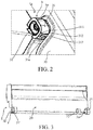
- the refrigeration appliance may further comprise shelves, storage containers and so on (not shown in the drawing) which are contained in the storage chamber 1a, and refer to FIG. 2 and FIG. 3 , each connecting assembly 3 may comprise an accommodating space 3a and a support shaft 30 arranged in the accommodating space 3a, for example, the accommodating space 3a can be arranged on the cover plate 2 and the support shaft 30 can be arranged on the side wall 10 of the storage chamber 1a.
- the cover plate 2 can rotate between the first position (horizontal position) and the second position (vertical position) around the support shaft 30, for example, at the vertical position shown in FIG. 1 , the cover plate 2, which is located at the position of the opening 1aa of the storage chamber 1 a, can cover the shelves to block food on the shelves from dropping.
- the arranged cover plate 2 is turned out of the storage chamber 1 a from the second position (vertical position) shown in FIG. 1 to the first position (horizontal position) to be exposed from the shelves.
- a circumferential wall 31 of the accommodating space 3a is provided with a gap 31 a, and the support shaft 30 is suitable for entering via the gap 31 a and being defined in the accommodating space 3a.
- the cover plate 2 is arranged at the position of the opening 1aa of the storage chamber 1a, so that the gap 31a is aligned with the side surface of the support shaft 30; the support shaft 30 then enters the accommodating space 3a via the gap 31 a (refer to FIG. 3 ), and thereby the cover plate 2 is quickly and conveniently mounted on the side wall 10.
- the cover plate 2 adjoins the corresponding side wall 10 of the storage chamber 1 a, so that the circumferential wall 31 of the accommodating space 3a interferes with the support shaft 30, so that the support shaft 30 cannot be directly inserted into the corresponding accommodating space 3a along the axial direction, and by arranging the gap 31 a in the circumferential wall 31, the support shaft 30 can be easily installed into the accommodating space 3a via the gap 31 a.
- the circumferential wall 31 of the accommodating space 3a may be provided with the gap 31 a (the gap in FIG. 1 is downwardly formed and is invisible, please refer to FIG. 2 ).
- the circumferential wall 31' of the accommodating space 3a makes a circle along a circumferential direction without forming a gap.
- the left support shaft (not shown in FIG. 3 ) can be inserted into the accommodating space along the axial direction, however, the right support shaft 30 shown in FIG. 1 can only be inserted into the accommodating space 3a via the gap 31 a, and this can make the advantages of the present technical solution more outstanding.
- the circumferential wall of the accommodating space may be provided with a gap, or for the connecting assemblies corresponding to the left side wall and the right side wall, the circumferential wall of each accommodating space is provided with a gap.
- the circumferential wall of the accommodating space is provided with the gap.
- the circumferential wall 31 of the accommodating space 3a is provided with a side accommodating wall which faces a bottom wall 11 of the storage chamber 1a at the vertical position, and refer to FIG. 2 , the side accommodating wall serves as a first accommodating wall 311, wherein the gap 31a is formed in the first accommodating wall 311.
- the cover plate 2 rotates from the second position (vertical position) to the first position (horizontal position) around the support shaft 30, then the first accommodating wall 311 arrives at a position facing the inside of the storage chamber 1a from the position facing the bottom wall 11 of the storage chamber 1a.
- the cover plate 2 can be horizontally placed first, so that the gap 31 a faces the inside of the storage chamber 1 a and is aligned with the support shaft 30, and the cover plate 2 is then pushed from the outside into the storage chamber 1 a until the support shaft 30 is completely defined in the accommodating space 3a (refer to FIG. 3 ).
- the cover plate 2 can be vertically placed first, so that the gap 31 a faces the bottom wall 11 of the storage chamber 1 a and is aligned with the support shaft 30, and the cover plate 3 is then downwardly moved until the support shaft 30 enters the accommodating space 3a.
- the first accommodating wall 311 faces the bottom wall 11 of the storage chamber 1 a and is invisible, and when a user opens a door of the refrigeration appliance, the gap 31a will not affect the appearance.
- the first accommodating wall 311 faces the inside of the storage chamber 1a, and the gap 31a will not affect the aesthetic feeling of the user.
- the width of the gap 31 a is less than or equal to the maximum diameter of the support shaft 30, wherein the width of the gap 31 a means the distance between two oppositely arranged boundaries 312 of the gap 31 a.
- a certain magnitude of interference exists between the gap 31 a and the support shaft 30.
- the support shaft 30 can overcome the magnitude of interference to be squeezed into the gap 31 a until the support shaft 30 arrives in the accommodating space 3a (refer to FIG. 3 ).
- the support shaft 30 cannot easily get out of the gap 31 a anymore, thereby keeping the stability of initial installation.
- the connecting assembly 3 may further comprises a stopper 32.
- the stopper 32 is arranged between the support shaft 30 and the accommodating space 3a to cover the gap 31 a; while a certain magnitude of interference exists between the gap 31 a and the support shaft 30 for blocking the support shaft 30 from getting out, the stopper 32 can better block the support shaft 30 from getting out of the gap 31a, and this can ensure that in the long-term operation process of the cover plate 2, the support shaft 30 can be stably and steadily fitted with the accommodating space 3a without easily getting out.
- the accommodating space 3a can be arranged on the cover plate 2 and is a through hole with openings at both ends. During assembly, the support shaft 30 can pass through the opening of one end, and then the stopper 32 is then installed between the support shaft 30 and the accommodating space 3a from the opening of the other end. As shown in FIG. 3 , the left accommodating space 3a' is a slot with an opening at only one end, and during assembly, the support shaft (not shown in the drawing) can be directly inserted into the slot along the axial direction.
- the stopper 32 may be arranged as a shaft sleeve, and is tightly fitted with the accommodating space 3a for fixing.
- the shaft sleeve is in clearance fit with the support shaft 30, and a moving clearance for the support shaft 30 is reserved.
- the shaft sleeve may be arranged to fixedly sheathe the support shaft, for example, forming overtight fit, and this is equivalent to an increase in the maximum diameter of the support shaft, thus preventing the support shaft from getting out of the gap.
- the connecting assembly may not comprise the stopper, but only depends on the magnitude of interference between the gap and the support shaft to achieve the anti-separation arrangement of the support shaft.
- the cover plate 2 is provided with an outer wall surface 20 facing the outside of the storage chamber 1a at the vertical position; refer to FIG. 3 , external projections 21 are projected from the outer wall surface 20, and the through holes (the accommodating spaces 3a) are formed in the external projections 21. This can prevent the through holes from being directly formed in the cover plate 2 to damage the cover plate 2.
- the refrigeration appliance may further comprise a support part 4, and the support part 4 extends into the storage chamber 1a from the side wall 10 of the storage chamber 1 a (refer to FIG. 2 ).
- the support shaft 30 is arranged on the support part 4, at least at the second position (vertical position) and the first position (horizontal position), referring to FIG. 1 , the cover plate 2 can be supported by the support part 4 (in FIG. 1 , the support part is covered and therefore is invisible) to keep stable.
- the support part 4 is covered by the cover plate 2 and therefore is invisible, so the user can have a good aesthetic feeling when opening the door.
- the fixed end of the support part 4 is located between the shell and liner of the refrigeration appliance and limited, and the free end of the support part 4 passes through the side wall 10 and extends into the storage chamber 1 a.
- the support shaft 30 can be arranged at the end, close to the outside of the storage chamber 1a, of the support part 4, so that it is possible to enable the cover plate 2 to cover the support part 4 at the vertical position.
- the accommodating space 5a may be a slot, and refer to FIG. 6 , the accommodating space 5a (in FIG. 6 , the accommodating space is covered and therefore is invisible) faces the side wall 10 of the storage chamber 1 a on the same side.
- the stopper 52 can be fixed in the gap 5b to play the role of blocking the support shaft (not shown in the drawing) from getting out of the gap 5b.
- the stopper 52 may be in tight fit with the gap 5b and thereby can be fixed in the gap 5b.
- the gap 5b is provided with two oppositely arranged side boundaries 51.
- the boundary 51 comprises a first surface 511 facing the outside of the accommodating space 5a, a second surface 512 located on the side of the first surface 511 far from the accommodating space 5a, and a third surface 513 located on the side of the first surface 511 close to the accommodating space 5a, and there are angles between the first surface 511 and the second surface 512 and between the first surface 511 and the third surface 513.
- the second surface 512 and the third surface 513 are located on two sides of the first surface 511 and connected to the first surface 511, and thereby a step portion is formed on the boundary 51.
- the stopper 52 is provided with side wall surfaces which match the boundaries 51, so that the stopper 52 keeps matching with the boundaries 51 when fixed in the gap 5b. As the stopper 52 is fitted with the gap 5b by means of the step-like portions, the contact area of the two can be enlarged, so that the stopper 52 can be more tightly defined in the gap 5b without easily getting out.
- the stopper 52 may be provided with claws 521, the claws 521 are projected into the accommodating space 5a, an inner wall surface 514 of the accommodating space 5a may be provided with a slot 5c, and refer to FIG. 7 , the claw 520 may be fastened in the slot 5c (in FIG. 7 , the slot is covered by the claws 520). Thereby the claws 520 have a limiting effect, so that the stopper 52 can better keep fixed and cannot easily get out.
- the stopper 52 is provided with two claws 520 which respectively correspond to the positions of the two side boundaries 51.
- each claw 520 is squeezed by the third surface 513 to elastically deform, and after sliding by the third surface 513, the claw 520 is restored to the original state and fastened in the slot 5c.
- the circumferential wall of the accommodating space 5a comprises a second accommodating wall 515 which faces the inside of the storage chamber at the vertical position, and the gap 5b is formed in the second accommodating wall 515.
- the second accommodating wall 515 can be covered by the cover plate 6 and is invisible, so enhancing the aesthetic feeling of the user.
- the cover plate 6 is provided with plate wall surfaces 60; refer to FIG. 6 , the plate wall surfaces 60 may face the side walls 10 of the storage chamber 1a, the accommodating spaces 5a may be arranged on the cover plate 6, the accommodating space 5a (in FIG. 6 , the accommodating space is invisible) may extend along the width direction of the refrigeration appliance to be flushed with the plate wall surface 60, and thus the projection for forming the accommodating space 5a is prevented from protruding out of the plate wall surface 60 and thereby is prevented from interfering with the side wall 10.
- the accommodating space may be arranged on the side of the plate wall surface facing away from the side wall.
- a support part 11 is formed on the side wall 10 of the storage chamber 1 a, and the support part 11 is provided with a projection 12 projected away from the side wall 10.
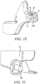
- the projection 12 is provided with an accommodating space 7a, so that the accommodating space 7a is arranged on the side wall 10 of the storage chamber 1 a, and a gap 7b is upwardly formed.
- the support shaft 80 is arranged on the cover plate 8, and can downwardly drop into the gap 7b and then get into the accommodating space 7a.
- the circumferential wall of the accommodating space 7a may further comprise a third accommodating wall 71 which faces the top wall of the storage chamber 1a at the vertical position, and the gap 7b is formed in the third accommodating wall 71.
- the gap 7b cannot be easily seen.
- the gap 7b is defined by two elastic pieces 72, the two elastic pieces 72 are suitable for extending so that the gap 7b opens to let the support shaft 80 (refer to FIG. 9 ) to pass through the gap 7b, and suitable for being restored to the original state after the support shaft 80 enters the accommodating space 7a from the gap 7b, consequently, the width of the gap 7b is reduced to the width of an initial shrunk gap, and the shrunk gap limits the support shaft 80, thus preventing it from getting out.
Landscapes
- Engineering & Computer Science (AREA)
- Mechanical Engineering (AREA)
- Chemical & Material Sciences (AREA)
- Combustion & Propulsion (AREA)
- Physics & Mathematics (AREA)
- Thermal Sciences (AREA)
- General Engineering & Computer Science (AREA)
- Residential Or Office Buildings (AREA)
- Refrigerator Housings (AREA)
Abstract
Disclosed is a refrigeration appliance, comprising a storage chamber (1a), a cover plate (2, 6, 8) arranged at the position of an opening (1aa) of the storage chamber (1a), and connecting assemblies (3) connecting side walls (10) of the storage chamber (1a) with the cover plate (2, 6, 8), each connecting assembly (3) comprises an accommodating space (3a, 3a', 5a, 7a) and a support shaft (30, 80) arranged in the accommodating space (3a, 3a', 5a, 7a), and the cover plate (2, 6, 8) can rotate between a horizontal position and a vertical position around the support shaft (30, 80); a circumferential wall (31, 311, 515, 71) of each accommodating space (3a, 5a, 7a) is provided with a gap (31a, 5b, 7b), and the support shaft (30, 80) is suitable for entering from the gap (31a, 5b, 7b) and being defined within the accommodating space (3a, 5a, 7a). In the refrigeration appliance of the present technical solution, the cover plate (2, 6, 8) is highly feasible and convenient to assemble, particularly for the case that the support shaft (30, 80) is mounted on the side wall (10) of the storage chamber (1a) in advance.
Description
- The present application relates to a refrigeration appliance, such as a refrigerator.
- A type of conventional refrigeration appliance, such as a refrigerator, comprises a storage chamber, shelves arranged in the storage chamber, and a turnable cover plate arranged at the position of the opening of the storage chamber, and the cover plate can be turned between a horizontal position and a vertical position, and can cover the shelves and articles thereon at the vertical position.
- In a type of product, support parts are first mounted on two side walls of the cover plate, the support parts are provided with support shafts, the support shafts pass through accommodating spaces arranged in the cover plate, such as slots or holes, the support parts are then fixed on the side walls of the storage chamber, and thereby the cover plate can rotate around the support shafts.
- However, in another type of product, the support parts have to be mounted on the side walls of the storage chamber in advance. For example, the support parts are fixed in a foam layer between a shell and a liner of the refrigeration appliance in advance, and pass through the side walls of the storage chamber to extend into the storage chamber, so the support parts must be assembled on the refrigeration appliance first. The support shafts which correspond to the positions of the two side walls are axially projected into the storage chamber, so that the support shafts cannot be directly inserted into the accommodating spaces along an axial direction, and as a result, a barrier is created to the installation of the cover plate.
- One objective of the present application is to provide a refrigeration appliance which is feasible and convenient to assemble.
- In order to solve the above-mentioned object, the present application provides a refrigeration appliance. The refrigeration appliance comprises a storage chamber, a cover plate arranged at the position of an opening of the storage chamber, and connecting assemblies connecting side walls of the storage chamber with the cover plate, each connecting assembly comprises an accommodating space and a support shaft arranged in the accommodating space, and the cover plate can rotate between a first position (horizontal position) and a second position (vertical position) around the support shafts; a circumferential wall of each accommodating space is provided with a gap, and the support shafts are suitable for entering from the gaps and being defined within the accommodating spaces.
- During assembly, the gaps can be aligned with the side surfaces of the support shafts, so that the support shafts can enter the accommodating spaces via the gaps, and thereby the cover plate can be quickly and conveniently installed on the side walls of the storage chamber. Especially, when the support shafts have been mounted on the corresponding side walls of the storage chamber in advance, the cover plate adjoins the corresponding side walls of the storage chamber, so that the circumferential walls of the accommodating spaces are in installation interference with the support shafts, as a result, the support shafts cannot be directly inserted into the corresponding accommodating spaces along the axial direction, but the support shafts can be easily installed into the accommodating spaces via the gaps, and thereby the feasibility and convenience of the assembly of the cover plate are increased.
- Preferably, for the connecting assembly corresponding to at least one of the two side walls of the storage chamber, the circumferential wall of the accommodating space may be provided with the gap. For example, the connecting assembly corresponding to only one side wall may be provided with a gap, or the connecting assemblies corresponding to the two side walls are both may be provided with gaps.
- Preferably, the circumferential wall of the accommodating space may comprise three side accommodating walls that face the inside, top wall and bottom wall of the storage chamber in the vertical position, and the gap may be formed in one of the three side accommodating walls. At the vertical position, the gaps may be formed in the three side accommodating walls facing the inside, top wall and bottom wall of the storage chamber, and when a user opens a door of the refrigeration appliance, the accommodating walls in which the gaps are formed are invisible, thereby enhancing the aesthetic feeling of the user.
- Preferably, the width of the gap may be less than or equal to the maximum diameter of the support shaft. The width of the gap means the distance between two oppositely arranged boundaries of the gap. Thus, a certain magnitude of interference may exist between the gap and the support shaft. During assembly, strength needs to be exerted, so that the support shaft can overcome the magnitude of interference to be squeezed into the gap until the support shaft arrives in the accommodating space. Thus, at least when being initially installed into the accommodating space, the support shaft may not be easily get out of the gap anymore, thereby keeping the stability of initial installation. Especially, in the process of operation, depending on the certain magnitude of interference between the support shaft and the gap, the support shaft may be prevented from getting out of the gap.
- Preferably, the connecting assembly may further comprise a stopper fixed in the gap or disposed between the support shaft and the accommodating space to cover the gap. Thus, the stopper may block the support shaft from getting out of the gap.
- Preferably, the stopper may be tightly fitted with the gap, and thereby may be fixed in the gap. In this embodiment, the assembly of the stopper may be simple, the stopper may be made by using a material suitable for elastic deformation, such as plastic, and thereby may be elastically deformed in the process of being squeezed into the gap to be tightly fixed in the gap.
- Preferably, the stopper may be provided with claws projected into the accommodating space, an inner wall surface of the accommodating space may be provided with a slot, and the claws may be fastened in the slot. The claws may enhance the fixing effect of the stopper, and prevent the stopper from falling off.
- Alternatively, the gap may be provided with two side boundaries which are oppositely arranged, and each boundary may comprise a first surface facing the outside of the accommodating space, a second surface located on the side of the first surface far from the accommodating space, and a third surface located on the side of the first surface close to the accommodating space, and there are angles between the first surface and the second surface and between the first surface and the third surface; and the stopper fits the boundaries.
- In this case, for each boundary of the gap, the first surface may be connected with the second surface and the third surface, forming a step portion. Correspondingly, the stopper may match the boundaries, it may be that the stopper is provided with step sections which match the step portions, and the two are in tight contact. Such a step structure may enhance the contact area between the stopper and the boundaries, the stopper may be more tightly defined in the gap, and thereby the stopper is steadier, not easily getting out of the gap.
- Preferably, the accommodating space may be arranged on the cover plate and may be a through hole having openings at two ends, and the support shaft passes through the opening of one end and the stopper is mounted between the support shaft and the accommodating space from the opening of the other end.
- Preferably, the cover plate may be provided with an outer wall surface facing the outside of the storage chamber at the vertical position, external projections may be projected from the outer wall surface, and the through holes may be formed in the external projections.
- Prefereably, the stopper may be a shaft sleeve, which surrounds the support shaft and may be fixed on the inner wall of the accommodating space or fixedly mounted on the outside of the support shaft. The shaft sleeve may cover the gap, thus preventing the support shaft from dropping into the gap.
- Preferably, the accommodating spaces may be arranged on the side walls, and the gaps may be formed upward. In such an embodiment, the support shafts may be formed on the cover plate, and the support shafts may downwardly drop into the gaps, and thereby enter the accommodating spaces, so that the cover plate is assembled.
- Prefereably, the gap may be defined by two elastic pieces, and the two elastic pieces may be suitable for extending so that the gap opens to let the support shaft to pass through the gap, and suitable for being restored to the original state after the support shaft enters the accommodating space from the gap.
- Preferably, the cover plate may be provided with plate wall surfaces facing the side walls, the accommodating space may be arranged in the cover plate, the accommodating space may extend to be flushed with the plate wall surface, or the accommodating space may be disposed on the side of the plate wall surface facing away from the side wall.
- Thus, the projections used for forming the accommodating spaces may be prevented from being projected from the plate wall surfaces, and thereby may be prevented from interfering with the side walls of the storage chamber.
- Preferably, the refrigeration appliance may further comprise support parts extending into the storage chamber from the side walls to support the cover plate, and the support shafts may be disposed in the support parts.
- Preferably, the accommodating spaces may be through holes or slots.
-
-
FIG. 1 is a three-dimensional diagram of a refrigeration appliance of the first embodiment of the present application; -
FIG. 2 shows the structure of a connecting assembly in the refrigeration appliance shown inFIG. 1 ; -
FIG. 3 is a three-dimensional diagram of a cover plate in the connecting assembly of the first embodiment of the present application; -
FIG. 4 shows a three-dimensional diagram of a support part of the refrigeration appliance; -
FIG. 5 is a three-dimensional diagram of a cover plate in the refrigeration appliance of the second embodiment of the present application; -
FIG. 6 shows a connecting relation of the connecting assembly in the refrigeration appliance of the second embodiment of the present application; -
FIG. 7 shows the connection state of an accommodating space and a stopper on the cover plate of the second embodiment; -
FIG. 8 shows the separation state of the accommodating space and the stopper on the cover plate of the second embodiment; -
FIG. 9 shows the assembled state of the connecting assembly in the refrigeration appliance of the second embodiment; -
FIG. 10 is a three-dimensional diagram of a support part in the refrigeration appliance of the second embodiment; and -
FIG. 11 shows a three-dimensional diagram in which a support shaft of the second embodiment is arranged on the cover plate. - In order to make the above-mentioned objective, features and advantages of the present application clearer and easier to understand, the specific embodiments of the present application will be described in detail with reference to the accompanying drawings below.
- Refer to
FIG. 1 , a refrigeration appliance, such as a refrigerator, comprises a storage chamber 1 a, acover plate 2 arranged at the position of an opening 1aa of the storage chamber 1a, and connectingassemblies 3 connectingside walls 10 of the storage chamber 1a with thecover plate 2. The refrigeration appliance may further comprise shelves, storage containers and so on (not shown in the drawing) which are contained in the storage chamber 1a, and refer toFIG. 2 and FIG. 3 , each connectingassembly 3 may comprise anaccommodating space 3a and asupport shaft 30 arranged in theaccommodating space 3a, for example, theaccommodating space 3a can be arranged on thecover plate 2 and thesupport shaft 30 can be arranged on theside wall 10 of the storage chamber 1a. Thecover plate 2 can rotate between the first position (horizontal position) and the second position (vertical position) around thesupport shaft 30, for example, at the vertical position shown inFIG. 1 , thecover plate 2, which is located at the position of the opening 1aa of the storage chamber 1 a, can cover the shelves to block food on the shelves from dropping. When food needs to be taken out of or stored into the storage chamber 1 a, the arrangedcover plate 2 is turned out of the storage chamber 1 a from the second position (vertical position) shown inFIG. 1 to the first position (horizontal position) to be exposed from the shelves. Acircumferential wall 31 of theaccommodating space 3a is provided with agap 31 a, and thesupport shaft 30 is suitable for entering via thegap 31 a and being defined in theaccommodating space 3a. - In the process of assembly, the
cover plate 2 is arranged at the position of the opening 1aa of the storage chamber 1a, so that thegap 31a is aligned with the side surface of thesupport shaft 30; thesupport shaft 30 then enters theaccommodating space 3a via thegap 31 a (refer toFIG. 3 ), and thereby thecover plate 2 is quickly and conveniently mounted on theside wall 10. Especially, when thesupport shaft 30 has been mounted on thecorresponding side wall 10 in advance, thecover plate 2 adjoins thecorresponding side wall 10 of the storage chamber 1 a, so that thecircumferential wall 31 of theaccommodating space 3a interferes with thesupport shaft 30, so that thesupport shaft 30 cannot be directly inserted into the correspondingaccommodating space 3a along the axial direction, and by arranging thegap 31 a in thecircumferential wall 31, thesupport shaft 30 can be easily installed into theaccommodating space 3a via thegap 31 a. - Refer to
FIG. 1 andFIG. 2 , among the twoside walls 10 of the storage chamber 1 a, for the connectingassembly 3 corresponding to theright side wall 10, thecircumferential wall 31 of theaccommodating space 3a may be provided with thegap 31 a (the gap inFIG. 1 is downwardly formed and is invisible, please refer toFIG. 2 ). Refer toFIG. 3 , for the connecting assembly 3' corresponding to the left side wall 10', the circumferential wall 31' of theaccommodating space 3a makes a circle along a circumferential direction without forming a gap. During assembly, the left support shaft (not shown inFIG. 3 ) can be inserted into the accommodating space along the axial direction, however, theright support shaft 30 shown inFIG. 1 can only be inserted into theaccommodating space 3a via thegap 31 a, and this can make the advantages of the present technical solution more outstanding. - In a modified solution, only for the connecting assembly corresponding to the right side wall, the circumferential wall of the accommodating space may be provided with a gap, or for the connecting assemblies corresponding to the left side wall and the right side wall, the circumferential wall of each accommodating space is provided with a gap.
- Therefore, for the connecting assembly corresponding to at least one side wall, the circumferential wall of the accommodating space is provided with the gap.
- Refer to
FIG. 1 , thecircumferential wall 31 of theaccommodating space 3a is provided with a side accommodating wall which faces abottom wall 11 of the storage chamber 1a at the vertical position, and refer toFIG. 2 , the side accommodating wall serves as a firstaccommodating wall 311, wherein thegap 31a is formed in the firstaccommodating wall 311. When thecover plate 2 rotates from the second position (vertical position) to the first position (horizontal position) around thesupport shaft 30, then the firstaccommodating wall 311 arrives at a position facing the inside of the storage chamber 1a from the position facing thebottom wall 11 of the storage chamber 1a. During assembly, thecover plate 2 can be horizontally placed first, so that thegap 31 a faces the inside of the storage chamber 1 a and is aligned with thesupport shaft 30, and thecover plate 2 is then pushed from the outside into the storage chamber 1 a until thesupport shaft 30 is completely defined in theaccommodating space 3a (refer toFIG. 3 ). Or, during assembly, thecover plate 2 can be vertically placed first, so that thegap 31 a faces thebottom wall 11 of the storage chamber 1 a and is aligned with thesupport shaft 30, and thecover plate 3 is then downwardly moved until thesupport shaft 30 enters theaccommodating space 3a. - On one hand, there are a variety of assembly strategies to choose, and operation is easy; on the other hand, at the second position (vertical position), the first
accommodating wall 311 faces thebottom wall 11 of the storage chamber 1 a and is invisible, and when a user opens a door of the refrigeration appliance, thegap 31a will not affect the appearance. At the first position (horizontal position), the firstaccommodating wall 311 faces the inside of the storage chamber 1a, and thegap 31a will not affect the aesthetic feeling of the user. - Refer to
FIG. 2 , the width of thegap 31 a is less than or equal to the maximum diameter of thesupport shaft 30, wherein the width of thegap 31 a means the distance between two oppositely arrangedboundaries 312 of thegap 31 a. Thus, a certain magnitude of interference exists between thegap 31 a and thesupport shaft 30. During assembly, strength needs to be exerted, so that thesupport shaft 30 can overcome the magnitude of interference to be squeezed into thegap 31 a until thesupport shaft 30 arrives in theaccommodating space 3a (refer toFIG. 3 ). Thus, at least when being initially installed into theaccommodating space 3a, thesupport shaft 30 cannot easily get out of thegap 31 a anymore, thereby keeping the stability of initial installation. - In a preferred embodiment, refer to
FIG. 3 , the connectingassembly 3 may further comprises astopper 32. Refer toFIG. 2 , thestopper 32 is arranged between thesupport shaft 30 and theaccommodating space 3a to cover thegap 31 a; while a certain magnitude of interference exists between thegap 31 a and thesupport shaft 30 for blocking thesupport shaft 30 from getting out, thestopper 32 can better block thesupport shaft 30 from getting out of thegap 31a, and this can ensure that in the long-term operation process of thecover plate 2, thesupport shaft 30 can be stably and steadily fitted with theaccommodating space 3a without easily getting out. - The
accommodating space 3a can be arranged on thecover plate 2 and is a through hole with openings at both ends. During assembly, thesupport shaft 30 can pass through the opening of one end, and then thestopper 32 is then installed between thesupport shaft 30 and theaccommodating space 3a from the opening of the other end. As shown inFIG. 3 , the leftaccommodating space 3a' is a slot with an opening at only one end, and during assembly, the support shaft (not shown in the drawing) can be directly inserted into the slot along the axial direction. - The
stopper 32 may be arranged as a shaft sleeve, and is tightly fitted with theaccommodating space 3a for fixing. In addition, the shaft sleeve is in clearance fit with thesupport shaft 30, and a moving clearance for thesupport shaft 30 is reserved. Besides, in another modified embodiment, the shaft sleeve may be arranged to fixedly sheathe the support shaft, for example, forming overtight fit, and this is equivalent to an increase in the maximum diameter of the support shaft, thus preventing the support shaft from getting out of the gap. - Besides, in another modified embodiment, the connecting assembly may not comprise the stopper, but only depends on the magnitude of interference between the gap and the support shaft to achieve the anti-separation arrangement of the support shaft.
- Refer to
FIG. 1 , thecover plate 2 is provided with anouter wall surface 20 facing the outside of the storage chamber 1a at the vertical position; refer toFIG. 3 ,external projections 21 are projected from theouter wall surface 20, and the through holes (theaccommodating spaces 3a) are formed in theexternal projections 21. This can prevent the through holes from being directly formed in thecover plate 2 to damage thecover plate 2. - Refer to
FIG. 4 , the refrigeration appliance may further comprise asupport part 4, and thesupport part 4 extends into the storage chamber 1a from theside wall 10 of the storage chamber 1 a (refer toFIG. 2 ). Thesupport shaft 30 is arranged on thesupport part 4, at least at the second position (vertical position) and the first position (horizontal position), referring toFIG. 1 , thecover plate 2 can be supported by the support part 4 (inFIG. 1 , the support part is covered and therefore is invisible) to keep stable. Especially at the vertical position, thesupport part 4 is covered by thecover plate 2 and therefore is invisible, so the user can have a good aesthetic feeling when opening the door. The fixed end of thesupport part 4 is located between the shell and liner of the refrigeration appliance and limited, and the free end of thesupport part 4 passes through theside wall 10 and extends into the storage chamber 1 a. - The
support shaft 30 can be arranged at the end, close to the outside of the storage chamber 1a, of thesupport part 4, so that it is possible to enable thecover plate 2 to cover thesupport part 4 at the vertical position. - Refer to
FIG. 5 , theaccommodating space 5a may be a slot, and refer toFIG. 6 , theaccommodating space 5a (inFIG. 6 , the accommodating space is covered and therefore is invisible) faces theside wall 10 of the storage chamber 1 a on the same side. - Refer to
FIG. 7 , thestopper 52 can be fixed in thegap 5b to play the role of blocking the support shaft (not shown in the drawing) from getting out of thegap 5b. Thestopper 52 may be in tight fit with thegap 5b and thereby can be fixed in thegap 5b. - Refer to
FIG. 8 , thegap 5b is provided with two oppositely arrangedside boundaries 51. Taking one of theside boundaries 51 as an example, theboundary 51 comprises a first surface 511 facing the outside of theaccommodating space 5a, asecond surface 512 located on the side of the first surface 511 far from theaccommodating space 5a, and athird surface 513 located on the side of the first surface 511 close to theaccommodating space 5a, and there are angles between the first surface 511 and thesecond surface 512 and between the first surface 511 and thethird surface 513. Thereby thesecond surface 512 and thethird surface 513 are located on two sides of the first surface 511 and connected to the first surface 511, and thereby a step portion is formed on theboundary 51. Thestopper 52 is provided with side wall surfaces which match theboundaries 51, so that thestopper 52 keeps matching with theboundaries 51 when fixed in thegap 5b. As thestopper 52 is fitted with thegap 5b by means of the step-like portions, the contact area of the two can be enlarged, so that thestopper 52 can be more tightly defined in thegap 5b without easily getting out. - The
stopper 52 may be provided withclaws 521, theclaws 521 are projected into theaccommodating space 5a, aninner wall surface 514 of theaccommodating space 5a may be provided with aslot 5c, and refer toFIG. 7 , theclaw 520 may be fastened in theslot 5c (inFIG. 7 , the slot is covered by the claws 520). Thereby theclaws 520 have a limiting effect, so that thestopper 52 can better keep fixed and cannot easily get out. - Refer to
FIG. 8 , thestopper 52 is provided with twoclaws 520 which respectively correspond to the positions of the twoside boundaries 51. During assembly, when sliding by theboundary 51 of the same side and sliding by the innerthird surface 513, eachclaw 520 is squeezed by thethird surface 513 to elastically deform, and after sliding by thethird surface 513, theclaw 520 is restored to the original state and fastened in theslot 5c. - Refer to
FIG. 5 , the circumferential wall of theaccommodating space 5a comprises a secondaccommodating wall 515 which faces the inside of the storage chamber at the vertical position, and thegap 5b is formed in the secondaccommodating wall 515. Thus, at the vertical position, it is possible that the secondaccommodating wall 515 can be covered by thecover plate 6 and is invisible, so enhancing the aesthetic feeling of the user. - Further, the
cover plate 6 is provided with plate wall surfaces 60; refer toFIG. 6 , the plate wall surfaces 60 may face theside walls 10 of the storage chamber 1a, theaccommodating spaces 5a may be arranged on thecover plate 6, theaccommodating space 5a (inFIG. 6 , the accommodating space is invisible) may extend along the width direction of the refrigeration appliance to be flushed with theplate wall surface 60, and thus the projection for forming theaccommodating space 5a is prevented from protruding out of theplate wall surface 60 and thereby is prevented from interfering with theside wall 10. Besides, in another embodiment, the accommodating space may be arranged on the side of the plate wall surface facing away from the side wall. - Refer to
FIG. 9 , asupport part 11 is formed on theside wall 10 of the storage chamber 1 a, and thesupport part 11 is provided with a projection 12 projected away from theside wall 10. Refer toFIG. 10 , the projection 12 is provided with anaccommodating space 7a, so that theaccommodating space 7a is arranged on theside wall 10 of the storage chamber 1 a, and agap 7b is upwardly formed. Correspondingly, refer toFIG. 11 , thesupport shaft 80 is arranged on thecover plate 8, and can downwardly drop into thegap 7b and then get into theaccommodating space 7a. - At this moment, refer to
FIG. 10 , the circumferential wall of theaccommodating space 7a may further comprise a thirdaccommodating wall 71 which faces the top wall of the storage chamber 1a at the vertical position, and thegap 7b is formed in the thirdaccommodating wall 71. Thus, at the vertical position, thegap 7b cannot be easily seen. - The
gap 7b is defined by twoelastic pieces 72, the twoelastic pieces 72 are suitable for extending so that thegap 7b opens to let the support shaft 80 (refer toFIG. 9 ) to pass through thegap 7b, and suitable for being restored to the original state after thesupport shaft 80 enters theaccommodating space 7a from thegap 7b, consequently, the width of thegap 7b is reduced to the width of an initial shrunk gap, and the shrunk gap limits thesupport shaft 80, thus preventing it from getting out. - Although the present application is disclosed as above, the present application is not limited to this. Any person skilled in the art can make various alterations and modifications without departing from the spirit and scope of the present application, so the protection scope of the present application should be subject to the scope defined by the claims.
Claims (16)
- A refrigeration appliance, comprising a storage chamber (1a), a cover plate (2, 6, 8) provided at the position of an opening (1aa) of the storage chamber (1a), and connecting assemblies (3) connecting side walls (10) of the storage chamber (1 a) with the cover plate (2, 6, 8), each connecting assembly (3) comprising an accommodating space (3a, 3a', 5a, 7a) and a support shaft (30, 80) provided within the accommodating space (3a, 3a', 5a, 7a), and the cover plate (2, 6, 8) being capable of rotating between a first position and a second position around the support shafts (30, 80), characterized in that a circumferential wall (31, 311, 515, 71) of each accommodating space (3a, 35a, 7a) is provided with a gap (31a, 5b, 7b), and the support shaft (30, 80) is suitable for entering from the gap (31 a, 5b, 7b) and being defined within the accommodating space (3a, 5a, 7a).
- The refrigeration appliance according to claim 1, characterized in that among the two side walls (10) of the storage chamber (1a), in the connecting assembly (3) corresponding to at least one side wall (10), the circumferential wall (31) of the accommodating space (3a, 5a, 7a) is provided with the gap (31 a, 5b, 7b).
- The refrigeration appliance according to claim 1, characterized in that the circumferential wall (31) of the accommodating space (3a, 5a, 7a) comprises three side accommodating walls (311, 515, 71) that face the inside, top wall and bottom wall of the storage chamber (1a) in the vertical position, and the gap (31 a, 5b, 7b) is formed in one of the three side accommodating walls (311, 515, 71).
- The refrigeration appliance according to claim 1, characterized in that the width of the gap (31 a, 5b, 7b) is less than or equal to a maximum diameter of the support shaft (30, 80).
- The refrigeration appliance according to claim 1, characterized in that the connecting assembly (3) further comprises a stopper (52) fixed in the gap (5b) or disposed between the support shaft (30) and the accommodating space (3a) to cover the gap (31 a).
- The refrigeration appliance according to claim 5, characterized in that the stopper (52) is tightly fitted with the gap (5b) so as to be fixed in the gap (5b).
- The refrigeration appliance according to claim 6, characterized in that the stopper (52) is provided with claws (521) projected into the accommodating space (5a), an inner wall surface (514) of the accommodating space (5a) is provided with a slot (5c), and the claw (521) is fastened in the slot (5c).
- The refrigeration appliance according to claim 6, characterized in that the gap (5b) is provided with two side boundaries (51) which are oppositely disposed, and each boundary (51) comprises a first surface (511) facing the outside of the accommodating space (5a), a second surface (512) located on the side of the first surface (511) far from the accommodating space (5a), and a third surface (513) located on the side of the first surface (511) close to the accommodating space (5a), and there are angles between the first surface (511) and the second surface (512) and between the first surface (511) and the third surface (513); and
the stopper (52) fits the boundaries (51). - The refrigeration appliance according to claim 5, characterized in that the accommodating space (3a) is disposed on the cover plate (2) and is a through hole having openings at two ends, and the support shaft (30) passes through the opening at one end and the stopper (32) is mounted between the support shaft (30) and the accommodating space (3a) from the opening at the other end.
- The refrigeration appliance according to claim 9, characterized in that the cover plate (2) is provided with an outer wall surface (20) facing the outside of the storage chamber (1 a) at the vertical position, external projections (21) are projected from the outer wall surface (20), and the through holes are formed in the external projections (21).
- The refrigeration appliance according to claim 9, characterized in that the stopper (32) is a shaft sleeve, which surrounds the support shaft (30) and is fixed on the inner wall of the accommodating space (3a) or fixedly mounted on the outside of the support shaft.
- The refrigeration appliance according to claim 1, characterized in that the accommodating space (7a) is disposed on the side wall (10), and the gap (7b) is formed upward.
- The refrigeration appliance according to claim 11, characterized in that the gap (7b) is defined by two elastic pieces (72), and the two elastic pieces (72) are suitable for extending so that the gap (7b) opens to let the support shaft (80) to pass through the gap (7b), and suitable for being restored to the original state after the support shaft (80) enters the accommodating space (7a) from the gap (7b).
- The refrigeration appliance according to claim 1, characterized in that the cover plate (6) is provided with a plate wall surface (60) facing the side wall (10), the accommodating space (5a) is arranged on the cover plate (6), the accommodating space (5a) extends to be flushed with the plate wall surface (60), or the accommodating space (5a) is disposed on the side of the plate wall surface (60) facing away from the side wall (10).
- The refrigeration appliance according to claim 1, characterized in that the refrigeration appliance further comprises support parts (4, 11) extending into the storage chamber (1 a) from the side walls (10) to support the cover plate (2, 6, 8), and the support shafts (30, 80) are disposed in the support parts (4, 11).
- The refrigeration appliance according to claim 1, characterized in that the accommodating spaces (3a, 5a, 7a) are through holes or slots.
Applications Claiming Priority (1)
| Application Number | Priority Date | Filing Date | Title |
|---|---|---|---|
| CN201720377443.1U CN206861994U (en) | 2017-04-12 | 2017-04-12 | Refrigerating appliance |
Publications (1)
| Publication Number | Publication Date |
|---|---|
| EP3388764A1 true EP3388764A1 (en) | 2018-10-17 |
Family
ID=60817157
Family Applications (1)
| Application Number | Title | Priority Date | Filing Date |
|---|---|---|---|
| EP18164267.9A Withdrawn EP3388764A1 (en) | 2017-04-12 | 2018-03-27 | Cooling appliance |
Country Status (2)
| Country | Link |
|---|---|
| EP (1) | EP3388764A1 (en) |
| CN (1) | CN206861994U (en) |
Families Citing this family (1)
| Publication number | Priority date | Publication date | Assignee | Title |
|---|---|---|---|---|
| CN113074477B (en) * | 2020-01-03 | 2023-09-15 | 博西华电器(江苏)有限公司 | refrigerator |
Citations (5)
| Publication number | Priority date | Publication date | Assignee | Title |
|---|---|---|---|---|
| DE2260605A1 (en) * | 1972-12-12 | 1974-06-20 | Licentia Gmbh | DOOR OR FLAP FOR LOCKING A REFRIGERATOR OR FREEZER COMPARTMENT |
| DE8903459U1 (en) * | 1989-03-20 | 1989-05-03 | Bosch-Siemens Hausgeräte GmbH, 8000 München | Cooling device, especially two-temperature refrigerator |
| DE10259065A1 (en) * | 2002-12-17 | 2004-07-01 | BSH Bosch und Siemens Hausgeräte GmbH | Door hinge for domestic appliances has cut-out to accept plastics moulded bearing bush having spring arms to retain hinge pin |
| WO2010131159A1 (en) * | 2009-05-13 | 2010-11-18 | Georg Utz Holding Ag | Hinge connection for a transport container made of plastic |
| WO2016155784A1 (en) * | 2015-03-31 | 2016-10-06 | Arcelik Anonim Sirketi | Refrigerator provided with a flap connection adaptor mechanism |
-
2017
- 2017-04-12 CN CN201720377443.1U patent/CN206861994U/en not_active Expired - Fee Related
-
2018
- 2018-03-27 EP EP18164267.9A patent/EP3388764A1/en not_active Withdrawn
Patent Citations (5)
| Publication number | Priority date | Publication date | Assignee | Title |
|---|---|---|---|---|
| DE2260605A1 (en) * | 1972-12-12 | 1974-06-20 | Licentia Gmbh | DOOR OR FLAP FOR LOCKING A REFRIGERATOR OR FREEZER COMPARTMENT |
| DE8903459U1 (en) * | 1989-03-20 | 1989-05-03 | Bosch-Siemens Hausgeräte GmbH, 8000 München | Cooling device, especially two-temperature refrigerator |
| DE10259065A1 (en) * | 2002-12-17 | 2004-07-01 | BSH Bosch und Siemens Hausgeräte GmbH | Door hinge for domestic appliances has cut-out to accept plastics moulded bearing bush having spring arms to retain hinge pin |
| WO2010131159A1 (en) * | 2009-05-13 | 2010-11-18 | Georg Utz Holding Ag | Hinge connection for a transport container made of plastic |
| WO2016155784A1 (en) * | 2015-03-31 | 2016-10-06 | Arcelik Anonim Sirketi | Refrigerator provided with a flap connection adaptor mechanism |
Also Published As
| Publication number | Publication date |
|---|---|
| CN206861994U (en) | 2018-01-09 |
Similar Documents
| Publication | Publication Date | Title |
|---|---|---|
| US8732910B1 (en) | Appliance handle assembly | |
| EP2741034B1 (en) | Refrigerator | |
| CN112282539B (en) | Refrigerator with baffle | |
| EP3244148B1 (en) | Refrigerator | |
| US12480705B2 (en) | Refrigerator | |
| EP3176524B1 (en) | Door shelf assembly and refrigerator having the same | |
| KR102391404B1 (en) | Refrigerator | |
| EP3564605B1 (en) | Refrigerator | |
| CN112282540A (en) | refrigerator with movable panel | |
| EP3070421B1 (en) | Refrigerator | |
| CN112282542A (en) | refrigerator with decorative sheet | |
| US20200173710A1 (en) | Refrigerator | |
| KR20150076940A (en) | Refrigerator | |
| CN112304007A (en) | Refrigerator with door opening stop structure | |
| CN112282538A (en) | Refrigerator with a door | |
| WO2002021057A1 (en) | Storage device of kimchi refrigerator | |
| JP2020531195A (en) | Storage shelf base and furniture or home appliances | |
| JP2016159975A (en) | Container for food and drink | |
| EP2843104A1 (en) | Door assembly for a laundry treatment device | |
| KR20190101596A (en) | Refrigerator | |
| KR20180013459A (en) | Refrigerator and Basket Assembly | |
| KR101838812B1 (en) | A refrigerator | |
| US20240060714A1 (en) | Method for installing a camera on an interior-compartment wall of a domestic appliance, and domestic appliance | |
| KR102498729B1 (en) | A refrigerator | |
| KR20120007896A (en) | Display unit mounting device of outdoor |
Legal Events
| Date | Code | Title | Description |
|---|---|---|---|
| PUAI | Public reference made under article 153(3) epc to a published international application that has entered the european phase |
Free format text: ORIGINAL CODE: 0009012 |
|
| AK | Designated contracting states |
Kind code of ref document: A1 Designated state(s): AL AT BE BG CH CY CZ DE DK EE ES FI FR GB GR HR HU IE IS IT LI LT LU LV MC MK MT NL NO PL PT RO RS SE SI SK SM TR |
|
| AX | Request for extension of the european patent |
Extension state: BA ME |
|
| STAA | Information on the status of an ep patent application or granted ep patent |
Free format text: STATUS: THE APPLICATION IS DEEMED TO BE WITHDRAWN |
|
| 18D | Application deemed to be withdrawn |
Effective date: 20190418 |