EP3388651A1 - Turbine engine gearbox assembly with sets of inline gears - Google Patents
Turbine engine gearbox assembly with sets of inline gears Download PDFInfo
- Publication number
- EP3388651A1 EP3388651A1 EP18166670.2A EP18166670A EP3388651A1 EP 3388651 A1 EP3388651 A1 EP 3388651A1 EP 18166670 A EP18166670 A EP 18166670A EP 3388651 A1 EP3388651 A1 EP 3388651A1
- Authority
- EP
- European Patent Office
- Prior art keywords
- gears
- assembly
- torque transmission
- plane
- turbine engine
- Prior art date
- Legal status (The legal status is an assumption and is not a legal conclusion. Google has not performed a legal analysis and makes no representation as to the accuracy of the status listed.)
- Granted
Links
Images



Classifications
-
- F—MECHANICAL ENGINEERING; LIGHTING; HEATING; WEAPONS; BLASTING
- F02—COMBUSTION ENGINES; HOT-GAS OR COMBUSTION-PRODUCT ENGINE PLANTS
- F02C—GAS-TURBINE PLANTS; AIR INTAKES FOR JET-PROPULSION PLANTS; CONTROLLING FUEL SUPPLY IN AIR-BREATHING JET-PROPULSION PLANTS
- F02C7/00—Features, components parts, details or accessories, not provided for in, or of interest apart form groups F02C1/00 - F02C6/00; Air intakes for jet-propulsion plants
- F02C7/32—Arrangement, mounting, or driving, of auxiliaries
-
- F—MECHANICAL ENGINEERING; LIGHTING; HEATING; WEAPONS; BLASTING
- F16—ENGINEERING ELEMENTS AND UNITS; GENERAL MEASURES FOR PRODUCING AND MAINTAINING EFFECTIVE FUNCTIONING OF MACHINES OR INSTALLATIONS; THERMAL INSULATION IN GENERAL
- F16H—GEARING
- F16H1/00—Toothed gearings for conveying rotary motion
- F16H1/02—Toothed gearings for conveying rotary motion without gears having orbital motion
- F16H1/20—Toothed gearings for conveying rotary motion without gears having orbital motion involving more than two intermeshing members
- F16H1/22—Toothed gearings for conveying rotary motion without gears having orbital motion involving more than two intermeshing members with a plurality of driving or driven shafts; with arrangements for dividing torque between two or more intermediate shafts
-
- F—MECHANICAL ENGINEERING; LIGHTING; HEATING; WEAPONS; BLASTING
- F05—INDEXING SCHEMES RELATING TO ENGINES OR PUMPS IN VARIOUS SUBCLASSES OF CLASSES F01-F04
- F05D—INDEXING SCHEME FOR ASPECTS RELATING TO NON-POSITIVE-DISPLACEMENT MACHINES OR ENGINES, GAS-TURBINES OR JET-PROPULSION PLANTS
- F05D2250/00—Geometry
- F05D2250/30—Arrangement of components
- F05D2250/31—Arrangement of components according to the direction of their main axis or their axis of rotation
-
- F—MECHANICAL ENGINEERING; LIGHTING; HEATING; WEAPONS; BLASTING
- F05—INDEXING SCHEMES RELATING TO ENGINES OR PUMPS IN VARIOUS SUBCLASSES OF CLASSES F01-F04
- F05D—INDEXING SCHEME FOR ASPECTS RELATING TO NON-POSITIVE-DISPLACEMENT MACHINES OR ENGINES, GAS-TURBINES OR JET-PROPULSION PLANTS
- F05D2260/00—Function
- F05D2260/40—Transmission of power
- F05D2260/403—Transmission of power through the shape of the drive components
- F05D2260/4031—Transmission of power through the shape of the drive components as in toothed gearing
Definitions
- This disclosure relates generally to a gas turbine engine and, more particularly, to a gearbox assembly for a gas turbine engine.
- a typical gas turbine engine includes a gearbox to transmit torque between a spool of the gas turbine engine and a plurality of turbine engine accessories. While various gearbox types and configurations are known in the art, there is still room for improvement.
- an assembly for a gas turbine engine with an axial centerline.
- This gas turbine engine assembly includes a gearbox, a first transmission apparatus and a second transmission apparatus.
- the gearbox includes a plurality of first gears and a plurality of second gears.
- the first gears are meshed together in a first plane parallel with the axial centerline.
- the second gears are meshed together in a second plane parallel with the axial centerline.
- the first torque transmission apparatus is configured to drive the first gears.
- the second torque transmission apparatus is configured to drive the second gears.
- an assembly for a gas turbine engine with an axial centerline.
- This gas turbine engine assembly includes a gearbox, a first transmission apparatus and a second transmission apparatus.
- the gearbox includes a plurality of first gears and a plurality of second gears.
- the first gears are meshed together and respectively rotatable about parallel first gear axes.
- the second gears are meshed together and respectively rotatable about parallel second gear axes.
- Each of the first gear axes and each of the second gear axes is non-parallel with the axial centerline.
- the first torque transmission apparatus is configured to drive the first gears.
- the second torque transmission apparatus is configured to drive the second gears.
- this gas turbine engine assembly includes a first rotating assembly, a second rotating assembly and a gearbox.
- the first rotating assembly is rotatable about the axial centerline and includes a first rotor including a plurality of first rotor blades.
- the second rotating assembly is rotatable about the axial centerline and includes a second rotor including a plurality of second rotor blades.
- the gearbox includes a plurality of intermeshed first gears and a plurality of intermeshed second gears.
- Each of the first gears is rotatable about a respective first axis that is non-parallel with the axial centerline.
- Each of the second gears is rotatable about a respective second axis is non-parallel with the axial centerline.
- the first gears are driven by the first rotating assembly.
- the second gears are driven by the second rotating assembly.
- this gas turbine engine assembly includes a gearbox housing, a plurality of first gears, a plurality of second gears, a first torque transmission device and a second transmission device.
- the first gears are arranged within the gearbox housing and meshed together in a first plane.
- the second gears are arranged within the gearbox housing and meshed together in a second plane.
- the second plane is parallel with and spaced from the first plane.
- the first torque transmission device is configured to couple and transmit torque between the first tower shaft and one of the first gears.
- the second torque transmission device is configured to couple and transmit torque between the second tower shaft and one of the second gears.
- the first gears may be meshed together in a first plane parallel with the axial centerline.
- the second gears may be meshed together in a second plane parallel with the axial centerline.
- the second plane may be parallel with and/or spaced from the first plane.
- the second plane may be angularly offset from the first plane by an acute angle.
- the second gears may be configured rotatably independent from the first gears.
- the first gears may be configured rotatably independent from the second gears.
- One of the first gears may have a rotational axis that is non-parallel with the axial centerline.
- one of the second gears may have a rotational axis that is non-parallel with the axial centerline.
- One of the first gears may have a rotational axis that is substantially perpendicular to the first plane.
- one of the second gears may have a rotational axis that is substantially perpendicular to the second plane.
- the first torque transmission apparatus may be configured as or otherwise include a first tower shaft.
- the second torque transmission apparatus may be configured as or otherwise include a second tower shaft.
- the first torque transmission apparatus may be configured as or otherwise include a first bevel gear rotatably attached to one of the first gears.
- the second torque transmission apparatus may be configured as or otherwise include a second bevel gear rotatably attached to one of the second gears.
- the first bevel gear and the second bevel gear may be arranged within the gearbox.
- the assembly may include a first rotating assembly and a second rotating assembly that is rotationally discrete from the first rotating assembly.
- the first torque transmission apparatus may be configured to couple the first rotating assembly with the first gears.
- the second torque transmission apparatus may be configured to couple the second rotating assembly with the second gears.
- the first rotating assembly may include a first compressor rotor, a first turbine rotor and a first shaft that connects the first compressor rotor with the first turbine rotor.
- the second rotating assembly may include a second compressor rotor, a second turbine rotor and a second shaft that connects the second compressor rotor with the second turbine rotor.
- the assembly may include a first turbine engine accessory mounted to the gearbox and a second turbine engine accessory mounted to the gearbox.
- One of the first gears may be configured to respectively drive actuation of the first turbine engine accessory.
- One of the second gears may be configured to respectively drive actuation of the second turbine engine accessory.
- the first accessory may be configured as or otherwise include a generator.
- the first accessory may be configured as or otherwise include a pump.
- the first accessory may be configured as or otherwise include a transmission.
- the first plane may be parallel with an axial centerline of the gas turbine engine.
- the first gears may be configured to rotate independent of the second gears.
- the assembly may include a first torque transmission apparatus configured to transfer torque between the first rotating assembly and the first gears.
- the assembly may also or alternatively include a second torque transmission apparatus configured to transfer torque between the second rotating assembly and the second gears.
- Each of the first gear axes and/or each of the second gear axes may be substantially perpendicular to the axial centerline.
- FIG. 1 is a schematic illustration of a portion of an assembly 10 of a gas turbine engine.
- This gas turbine engine may be configured as a hi-bypass turbofan gas turbine engine for an aircraft propulsion system as generally illustrated in FIG. 1 (see also FIG. 6 , which is discussed below in further detail).
- the gas turbine engine may be configured as a turbojet gas turbine engine for an aircraft propulsion system, a gas turbine engine for a land-based power system, or any other type of gas turbine engine which can be configured with an accessory gearbox.
- the gas turbine engine assembly 10 of FIG. 1 includes a first rotating assembly 12 and a second rotating assembly 14.
- the gas turbine engine assembly 10 also includes a gearbox 16, a first torque transmission apparatus 18, a second torque transmission apparatus 20 and a plurality of turbine engine accessories 22-28 (see FIG. 2 ).
- turbine engine accessories include, but are not limited to, a fuel pump, a hydraulic pump, a lubrication pump, a transmission (e.g., reduction gear assembly) and an electrical generator.
- the first rotating assembly 12 may be configured as or may be included in a first spool (e.g., a low speed spool) of the gas turbine engine.
- the second rotating assembly 14 may be configured as or may be included in a second spool (e.g., a high speed spool) of the gas turbine engine.
- the second rotating assembly 14 is discrete from the first rotating assembly 12.
- the second rotating assembly 14 of FIG. 1 for example, is not attached to and, thus, can rotate independently from the first rotating assembly 12.
- the first and the second rotating assemblies 12 and 14, however, may both be rotatable - in the same direction or in different directions - about a common rotational axis 30; e.g., an axial centerline 32 of the gas turbine engine.
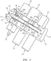
- the gearbox 16 includes a gearbox housing 34, a plurality of intermeshed first gears 36A-F (generically referred to as “36") and a plurality of intermeshed second gears 38A-G (generically referred to as “38").
- the gearbox 16 may also include one or more first torque transmission devices 40 and 42 and/or one or more second torque transmission devices 44 and 46.
- the first gears 36 are disposed and rotatably mounted within the gearbox housing 34.
- the first gears 36 are arranged and rotatable within a first plane 48; e.g., the plane of FIG. 4 . More particularly, the first plane 48 extends linearly through (and/or along) each of the first gears 36.
- Each of the first gears 36A-F also rotates about a respective rotational axis 50A-F that is substantially perpendicular to the first plane 48.
- the first plane 48 may be configured at least substantially in parallel with the axial centerline 32. With such a configuration, the rotational axes 50A-F of the first gears 36A-F are non-parallel with (e.g., substantially perpendicular to) the axial centerline 32.
- Each of the first gears 36 is meshed with at least another one of the first gears 36.
- the term "meshed” may describe an interface between a pair of gears where teeth of those gears at the interface mate and interlock together.
- the first gears 36 are thereby meshed together within the first plane 48.
- the first gear 36B is disposed between and meshed with the first gear 36A and the first gear 36C.
- the first gear 36C is disposed between and meshed with the first gear 36B and the first gear 36D.
- the first gear 36D is disposed between and meshed with the first gear 36C and the first gear 36E.
- the first gear 36E is disposed between and meshed with the first gear 36D and the first gear 36F. As shown in FIG.
- the first gears 36 may be arranged substantially inline with one another (e.g., along a straight, curved or tortuous line). However, in other embodiments, one or more of the first gears 36 may be disposed out-of-line, for example, in a similar manner as described below with reference to the second gear 38G in FIG. 5 .
- the first gear 36B is coupled with a drive shaft 52 of and thereby operable to actuate the accessory 22.
- the first gear 36D is coupled with a drive shaft 54 of and thereby operable to actuate the accessory 23.
- the first gear 36D is also coupled with a drive shaft 56 of and thereby operable to actuate the accessory 24.
- the second gear 36D is operable to rotate about the drive shaft 56 such that the first gears 36 can still rotate independently of the second gears 38.
- the first gear 36F is coupled with a drive shaft 58 of and thereby operable to actuate the accessory 25.
- the second gears 38 are also disposed and rotatably mounted within the gearbox housing 34. However, the second gears 38 are configured as rotatably independent from the first gears 36. For example, none of the second gears 38 is meshed with or otherwise fixedly attached to any of the first gears 36. Thereby, none of the second gears 38 is driven by or drives any of the first gears 36.
- the second gears 38 are arranged and rotatable within a second plane 60; e.g., the plane of FIG. 5 . More particularly, the second plane 60 extends linearly through (and/or along) each of the second gears 38. Each of the second gears 38A-G also rotates about a respective rotational axis 62A-G that is substantially perpendicular to the second plane 60.
- the second plane 60 may be configured at least substantially in parallel with the axial centerline 32. With such a configuration, the rotational axes 62A-G of the second gears 38A-G are non-parallel with (e.g., substantially perpendicular to) the axial centerline 32.
- the second plane 60 may also be configured substantially parallel, but spaced away from, the first plane 48. However, in other embodiments, the second plane 60 may be angularly offset from the first plane 48 by an acute included angle therebetween.
- the second plane 60 of FIG. 6 for example, is angularly offset from the first plane 48 by an acute angle 63.
- the first and the second planes 48 and 60 may be substantially parallel to the axial centerline 32.
- each of the second gears 38 is meshed with at least another one of the second gears 38.
- the term “meshed” may describe an interface between a pair of gears where teeth of those gears at the interface mate and interlock together.
- the second gears 38 are thereby meshed together within the second plane 60.
- the second gear 38B is disposed between and meshed with the second gear 38A and the second gear 38C.
- the second gear 38C is disposed between and meshed with the second gear 38B and the second gear 38D.
- the second gear 38D is disposed between and meshed with the second gear 38C and the second gear 38E.
- the second gear 38E is disposed between and meshed with the second gear 38D and the second gear 38F.
- the second gear 38E is also meshed with the second gear 38G, which is arranged out-of-line with the other second gears 38.
- one or more of the other second gears 38 may also or additionally be arranged out-of-line.
- all of the second gears 38 may be arranged substantially inline with one another.
- the second gear 38B is coupled with a drive shaft 64 of and thereby operable to actuate the accessory 26.
- the second gear 38F is coupled with a drive shaft 66 of and thereby operable to actuate the accessory 27.
- the second gear 38G is also coupled with a drive shaft 68 of and thereby operable to actuate the accessory 28.
- the first gears 36 and the second gears 38 may each be configured as a spur gear.
- the present disclosure is not limited to such an exemplary gear type.
- one or more of the gears may be configured as a helical gear or any other type of suitable gear.
- the first torque transmission devices 40 and 42 are disposed and rotatably mounted within the gearbox housing 34.
- Each of the first torque transmission devices 40 and 42 of FIG. 3 is configured as a bevel gear. However, in other embodiments, these torque transmission devices 40 and 42 may alternatively be configured as another type of gearing, transmission system and/or linkage assembly.
- the first torque transmission device 40 is fixedly attached to the first gear 36A, for example, through a shaft 70.
- the first torque transmission device 42 is meshed with the first torque transmission device 40.
- the first torque transmission device 42 is also configured to mate with another torque transmission device 72 such as, for example, a first tower shaft; see FIGS. 1 and 2 .
- second torque transmission devices 44 and 46 are disposed and rotatably mounted within the gearbox housing 34.
- Each of the second torque transmission devices 44 and 46 of FIG. 3 is configured as a bevel gear. However, in other embodiments, these torque transmission devices 44 and 46 may alternatively be configured as another type of gearing, transmission system and/or linkage assembly.
- the second torque transmission device 44 is fixedly attached to the second gear 38A, for example, through a shaft 74.
- the second torque transmission device 46 is meshed with the second torque transmission device 44.
- the second torque transmission device 46 is also configured to mate with another torque transmission device 76 such as, for example, a second tower shaft; see FIGS. 1 and 2 .
- the first torque transmission apparatus 18 includes one or more of the torque transmission devices 40, 42 and/or 72.
- the torque transmission device 72 e.g., the first tower shaft
- the torque transmission device 72 is configured to mechanically couple the first rotating assembly 12 with the first torque transmission device 42.
- the first rotating assembly 12 is operable to drive rotation of the first gears 36 through the first torque transmission apparatus 18.
- the second torque transmission apparatus 20 includes one or more of the torque transmission devices 44, 46 and/or 76.
- the torque transmission device 76 e.g., the second tower shaft
- the torque transmission device 76 is configured to mechanically couple the second rotating assembly 14 with the second torque transmission device 46.
- the second rotating assembly 14 is operable to drive rotation of the second gears 38 through the second torque transmission apparatus 20.
- the second rotating assembly 14 typically rotates at a different (e.g., higher) rotational velocity than the first rotating assembly 12.
- the turbine engine assembly 10 is operable to drive the accessories at different speeds without requiring the addition of a complicated reduction transmission within the gearbox 16.
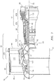
- FIG. 7 is a side cutaway illustration of an exemplary gas turbine engine 78 with which the turbine engine assembly 10 may be included.
- This turbine engine 78 extends along the axial centerline 32 between an upstream airflow inlet 80 and a downstream airflow exhaust 82.
- the turbine engine 78 includes a fan section 84, a compressor section 85, a combustor section 86 and a turbine section 87.
- the compressor section 85 includes a low pressure compressor (LPC) section 85A and a high pressure compressor (HPC) section 85B.
- the turbine section 87 includes a high pressure turbine (HPT) section 87A and a low pressure turbine (LPT) section 87B.
- the engine sections 84-87 are arranged sequentially along the centerline 32 within an engine housing 90.
- This housing 90 includes an inner case 92 (e.g., a core case) and an outer case 94 (e.g., a fan case).
- the inner case 92 may house one or more of the engine sections 85-87; e.g., an engine core.
- the outer case 94 may house at least the fan section 84.
- Each of the engine sections 84, 85A, 85B, 87A and 87B includes a respective rotor 96-100.
- Each of these rotors 96-100 includes a plurality of rotor blades arranged circumferentially around and connected to one or more respective rotor disks.
- the rotor blades may be formed integral with or mechanically fastened, welded, brazed, adhered and/or otherwise attached to the respective rotor disk(s).
- the fan rotor 96 is connected to a gear train 102, for example, through a fan shaft 104.
- the gear train 102 and the LPC rotor 97 are connected to and driven by the LPT rotor 100 through a low speed shaft 105.
- a combination of the rotors 96, 97 and 100, the gear train 102 and the shafts 104 and 105 may form the first rotating assembly 12 of FIG. 1 .
- the HPC rotor 98 is connected to and driven by the HPT rotor 99 through a high speed shaft 106.
- a combination of the rotors 98 and 99 and the shaft 106 may form the second rotating assembly 14 of FIG. 1 .
- the shafts 104-105 are rotatably supported by a plurality of bearings; e.g., rolling element and/or thrust bearings.
- a plurality of bearings e.g., rolling element and/or thrust bearings.
- Each of these bearings is connected to the engine housing 90 by at least one stationary structure such as, for example, an annular support strut.
- This air is directed through the fan section 84 and into a core gas path 108 and a bypass gas path 110.
- the core gas path 108 extends sequentially through the engine sections 85-87; e.g., an engine core.
- the air within the core gas path 108 may be referred to as "core air”.
- the bypass gas path 110 extends through a bypass duct, which bypasses the engine core.
- the air within the bypass gas path 110 may be referred to as "bypass air”.
- the core air is compressed by the compressor rotors 97 and 98 and directed into a combustion chamber of a combustor in the combustor section 86.
- Fuel is injected into the combustion chamber and mixed with the compressed core air to provide a fuel-air mixture.
- This fuel air mixture is ignited and combustion products thereof flow through and sequentially cause the turbine rotors 99 and 100 to rotate.
- the rotation of the turbine rotors 99 and 100 respectively drive rotation of the compressor rotors 98 and 97 and, thus, compression of the air received from a core airflow inlet.
- the rotation of the turbine rotor 100 also drives rotation of the fan rotor 96, which propels bypass air through and out of the bypass gas path 110.
- the propulsion of the bypass air may account for a majority of thrust generated by the turbine engine 78, e.g., more than seventy-five percent (75%) of engine thrust.
- the turbine engine 78 of the present disclosure is not limited to the foregoing exemplary thrust ratio.
- the turbine engine assembly 10 and its gearbox 16 may be included in various turbine engines other than the one described above.
- the turbine engine assembly 10, for example, may be included in a geared turbine engine where a gear train connects one or more shafts to one or more rotors in a fan section, a compressor section and/or any other engine section.
- the turbine engine assembly 10 may be included in a turbine engine configured without a gear train.
- the turbine engine assembly 10 may be included in a geared or non-geared turbine engine configured with two spools (e.g., see FIG. 7 ), or with more than two spools.
- the turbine engine may be configured as a turbofan engine, a turbojet engine, a propfan engine, a pusher fan engine or any other type of turbine engine.
- the present invention therefore is not limited to any particular types or configurations of turbine engines.
- first plane 48 in FIG. 3 is described above as being substantially parallel with the axial centerline 32.
- first plane 48 may be exactly parallel with the axial centerline 32, or slightly offset from parallel by no more than +/- 5 degrees.
Landscapes
- Engineering & Computer Science (AREA)
- General Engineering & Computer Science (AREA)
- Chemical & Material Sciences (AREA)
- Combustion & Propulsion (AREA)
- Mechanical Engineering (AREA)
- Gear Transmission (AREA)
Abstract
Description
- This disclosure relates generally to a gas turbine engine and, more particularly, to a gearbox assembly for a gas turbine engine.
- A typical gas turbine engine includes a gearbox to transmit torque between a spool of the gas turbine engine and a plurality of turbine engine accessories. While various gearbox types and configurations are known in the art, there is still room for improvement.
- According to an aspect of the present disclosure, an assembly is provided for a gas turbine engine with an axial centerline. This gas turbine engine assembly includes a gearbox, a first transmission apparatus and a second transmission apparatus. The gearbox includes a plurality of first gears and a plurality of second gears. The first gears are meshed together in a first plane parallel with the axial centerline. The second gears are meshed together in a second plane parallel with the axial centerline. The first torque transmission apparatus is configured to drive the first gears. The second torque transmission apparatus is configured to drive the second gears.
- According to another aspect of the present disclosure, an assembly is provided for a gas turbine engine with an axial centerline. This gas turbine engine assembly includes a gearbox, a first transmission apparatus and a second transmission apparatus. The gearbox includes a plurality of first gears and a plurality of second gears. The first gears are meshed together and respectively rotatable about parallel first gear axes. The second gears are meshed together and respectively rotatable about parallel second gear axes. Each of the first gear axes and each of the second gear axes is non-parallel with the axial centerline. The first torque transmission apparatus is configured to drive the first gears. The second torque transmission apparatus is configured to drive the second gears.
- According to another aspect of the present disclosure, another assembly is provided for a gas turbine engine with an axial centerline. This gas turbine engine assembly includes a first rotating assembly, a second rotating assembly and a gearbox. The first rotating assembly is rotatable about the axial centerline and includes a first rotor including a plurality of first rotor blades. The second rotating assembly is rotatable about the axial centerline and includes a second rotor including a plurality of second rotor blades. The gearbox includes a plurality of intermeshed first gears and a plurality of intermeshed second gears. Each of the first gears is rotatable about a respective first axis that is non-parallel with the axial centerline. Each of the second gears is rotatable about a respective second axis is non-parallel with the axial centerline. The first gears are driven by the first rotating assembly. The second gears are driven by the second rotating assembly.
- According to still another aspect of the present disclosure, another assembly is provided for a gas turbine engine with a first tower shaft and a second tower shaft. This gas turbine engine assembly includes a gearbox housing, a plurality of first gears, a plurality of second gears, a first torque transmission device and a second transmission device. The first gears are arranged within the gearbox housing and meshed together in a first plane. The second gears are arranged within the gearbox housing and meshed together in a second plane. The second plane is parallel with and spaced from the first plane. The first torque transmission device is configured to couple and transmit torque between the first tower shaft and one of the first gears. The second torque transmission device is configured to couple and transmit torque between the second tower shaft and one of the second gears.
- The first gears may be meshed together in a first plane parallel with the axial centerline. The second gears may be meshed together in a second plane parallel with the axial centerline.
- The second plane may be parallel with and/or spaced from the first plane.
- The second plane may be angularly offset from the first plane by an acute angle.
- The second gears may be configured rotatably independent from the first gears.
- The first gears may be configured rotatably independent from the second gears.
- One of the first gears may have a rotational axis that is non-parallel with the axial centerline. In addition or alternatively, one of the second gears may have a rotational axis that is non-parallel with the axial centerline.
- One of the first gears may have a rotational axis that is substantially perpendicular to the first plane. In addition or alternatively, one of the second gears may have a rotational axis that is substantially perpendicular to the second plane.
- The first torque transmission apparatus may be configured as or otherwise include a first tower shaft. In addition or alternatively, the second torque transmission apparatus may be configured as or otherwise include a second tower shaft.
- The first torque transmission apparatus may be configured as or otherwise include a first bevel gear rotatably attached to one of the first gears. In addition or alternatively, the second torque transmission apparatus may be configured as or otherwise include a second bevel gear rotatably attached to one of the second gears.
- The first bevel gear and the second bevel gear may be arranged within the gearbox.
- The assembly may include a first rotating assembly and a second rotating assembly that is rotationally discrete from the first rotating assembly. The first torque transmission apparatus may be configured to couple the first rotating assembly with the first gears. The second torque transmission apparatus may be configured to couple the second rotating assembly with the second gears.
- The first rotating assembly may include a first compressor rotor, a first turbine rotor and a first shaft that connects the first compressor rotor with the first turbine rotor. The second rotating assembly may include a second compressor rotor, a second turbine rotor and a second shaft that connects the second compressor rotor with the second turbine rotor.
- The assembly may include a first turbine engine accessory mounted to the gearbox and a second turbine engine accessory mounted to the gearbox. One of the first gears may be configured to respectively drive actuation of the first turbine engine accessory. One of the second gears may be configured to respectively drive actuation of the second turbine engine accessory.
- The first accessory may be configured as or otherwise include a generator.
- The first accessory may be configured as or otherwise include a pump.
- The first accessory may be configured as or otherwise include a transmission.
- The first plane may be parallel with an axial centerline of the gas turbine engine.
- The first gears may be configured to rotate independent of the second gears.
- The assembly may include a first torque transmission apparatus configured to transfer torque between the first rotating assembly and the first gears. The assembly may also or alternatively include a second torque transmission apparatus configured to transfer torque between the second rotating assembly and the second gears.
- Each of the first gear axes and/or each of the second gear axes may be substantially perpendicular to the axial centerline.
- The foregoing features and the operation of the invention will become more apparent in light of the following description and the accompanying drawings.
-
-
FIG. 1 is a schematic illustration of a portion of an assembly of a gas turbine engine. -
FIG. 2 is a perspective illustration of a gearbox configured with a plurality of torque transmission apparatuses and a plurality of turbine engine accessories, where a housing of the gearbox is shown as being semi-transparent. -
FIG. 3 is a schematic illustration of the gearbox and the turbine engine accessories. -
FIG. 4 is a schematic illustration of a plurality of first gears. -
FIG. 5 is a schematic illustration of a plurality of second gears. -
FIG. 6 is a schematic illustration of gear(s) in a first plane acutely angled to gear(s) in a second plane. -
FIG. 7 is side cutaway illustration of an exemplary gas turbine engine. -
FIG. 1 is a schematic illustration of a portion of anassembly 10 of a gas turbine engine. This gas turbine engine may be configured as a hi-bypass turbofan gas turbine engine for an aircraft propulsion system as generally illustrated inFIG. 1 (see alsoFIG. 6 , which is discussed below in further detail). Alternatively, the gas turbine engine may be configured as a turbojet gas turbine engine for an aircraft propulsion system, a gas turbine engine for a land-based power system, or any other type of gas turbine engine which can be configured with an accessory gearbox. - The gas
turbine engine assembly 10 ofFIG. 1 includes a firstrotating assembly 12 and a secondrotating assembly 14. The gasturbine engine assembly 10 also includes agearbox 16, a firsttorque transmission apparatus 18, a secondtorque transmission apparatus 20 and a plurality of turbine engine accessories 22-28 (seeFIG. 2 ). Examples of turbine engine accessories include, but are not limited to, a fuel pump, a hydraulic pump, a lubrication pump, a transmission (e.g., reduction gear assembly) and an electrical generator. - The first
rotating assembly 12 may be configured as or may be included in a first spool (e.g., a low speed spool) of the gas turbine engine. The secondrotating assembly 14 may be configured as or may be included in a second spool (e.g., a high speed spool) of the gas turbine engine. The secondrotating assembly 14 is discrete from the firstrotating assembly 12. The secondrotating assembly 14 ofFIG. 1 , for example, is not attached to and, thus, can rotate independently from the firstrotating assembly 12. The first and the secondrotating assemblies axial centerline 32 of the gas turbine engine. - Referring to
FIG. 2 , thegearbox 16 includes agearbox housing 34, a plurality of intermeshedfirst gears 36A-F (generically referred to as "36") and a plurality of intermeshedsecond gears 38A-G (generically referred to as "38"). Thegearbox 16 may also include one or more firsttorque transmission devices torque transmission devices - Referring to
FIG. 3 , thefirst gears 36 are disposed and rotatably mounted within thegearbox housing 34. Referring now toFIGS. 3 and4 , thefirst gears 36 are arranged and rotatable within afirst plane 48; e.g., the plane ofFIG. 4 . More particularly, thefirst plane 48 extends linearly through (and/or along) each of thefirst gears 36. Each of thefirst gears 36A-F also rotates about a respectiverotational axis 50A-F that is substantially perpendicular to thefirst plane 48. Thefirst plane 48 may be configured at least substantially in parallel with theaxial centerline 32. With such a configuration, therotational axes 50A-F of thefirst gears 36A-F are non-parallel with (e.g., substantially perpendicular to) theaxial centerline 32. - Each of the
first gears 36 is meshed with at least another one of thefirst gears 36. The term "meshed" may describe an interface between a pair of gears where teeth of those gears at the interface mate and interlock together. Thefirst gears 36 are thereby meshed together within thefirst plane 48. In the specific embodiment ofFIGS. 3 and4 , thefirst gear 36B is disposed between and meshed with thefirst gear 36A and thefirst gear 36C. Thefirst gear 36C is disposed between and meshed with thefirst gear 36B and thefirst gear 36D. Thefirst gear 36D is disposed between and meshed with thefirst gear 36C and thefirst gear 36E. Thefirst gear 36E is disposed between and meshed with thefirst gear 36D and thefirst gear 36F. As shown inFIG. 4 , thefirst gears 36 may be arranged substantially inline with one another (e.g., along a straight, curved or tortuous line). However, in other embodiments, one or more of thefirst gears 36 may be disposed out-of-line, for example, in a similar manner as described below with reference to thesecond gear 38G inFIG. 5 . - In the specific embodiment of
FIG. 3 , thefirst gear 36B is coupled with adrive shaft 52 of and thereby operable to actuate theaccessory 22. Thefirst gear 36D is coupled with adrive shaft 54 of and thereby operable to actuate theaccessory 23. Thefirst gear 36D is also coupled with adrive shaft 56 of and thereby operable to actuate theaccessory 24. Note, thesecond gear 36D is operable to rotate about thedrive shaft 56 such that thefirst gears 36 can still rotate independently of the second gears 38. Thefirst gear 36F is coupled with adrive shaft 58 of and thereby operable to actuate theaccessory 25. - The second gears 38 are also disposed and rotatably mounted within the
gearbox housing 34. However, the second gears 38 are configured as rotatably independent from thefirst gears 36. For example, none of the second gears 38 is meshed with or otherwise fixedly attached to any of thefirst gears 36. Thereby, none of the second gears 38 is driven by or drives any of thefirst gears 36. - Referring to
FIGS. 3 and5 , the second gears 38 are arranged and rotatable within asecond plane 60; e.g., the plane ofFIG. 5 . More particularly, thesecond plane 60 extends linearly through (and/or along) each of the second gears 38. Each of thesecond gears 38A-G also rotates about a respectiverotational axis 62A-G that is substantially perpendicular to thesecond plane 60. Thesecond plane 60 may be configured at least substantially in parallel with theaxial centerline 32. With such a configuration, therotational axes 62A-G of thesecond gears 38A-G are non-parallel with (e.g., substantially perpendicular to) theaxial centerline 32. Thesecond plane 60 may also be configured substantially parallel, but spaced away from, thefirst plane 48. However, in other embodiments, thesecond plane 60 may be angularly offset from thefirst plane 48 by an acute included angle therebetween. Thesecond plane 60 ofFIG. 6 , for example, is angularly offset from thefirst plane 48 by anacute angle 63. The first and thesecond planes axial centerline 32. - Referring again to
FIGS. 3 and5 , each of the second gears 38 is meshed with at least another one of the second gears 38. As described above, the term "meshed" may describe an interface between a pair of gears where teeth of those gears at the interface mate and interlock together. The second gears 38 are thereby meshed together within thesecond plane 60. In the specific embodiment ofFIGS. 3 and4 , thesecond gear 38B is disposed between and meshed with thesecond gear 38A and thesecond gear 38C. Thesecond gear 38C is disposed between and meshed with thesecond gear 38B and thesecond gear 38D. Thesecond gear 38D is disposed between and meshed with thesecond gear 38C and thesecond gear 38E. Thesecond gear 38E is disposed between and meshed with thesecond gear 38D and thesecond gear 38F. Thesecond gear 38E is also meshed with thesecond gear 38G, which is arranged out-of-line with the other second gears 38. Of course, in some embodiments, one or more of the other second gears 38 may also or additionally be arranged out-of-line. Alternatively, in other embodiments, all of the second gears 38 may be arranged substantially inline with one another. - In the specific embodiment of
FIG. 3 , thesecond gear 38B is coupled with adrive shaft 64 of and thereby operable to actuate theaccessory 26. Thesecond gear 38F is coupled with adrive shaft 66 of and thereby operable to actuate theaccessory 27. Thesecond gear 38G is also coupled with adrive shaft 68 of and thereby operable to actuate theaccessory 28. - The
first gears 36 and the second gears 38 may each be configured as a spur gear. However, the present disclosure is not limited to such an exemplary gear type. For example, in other embodiments, one or more of the gears may be configured as a helical gear or any other type of suitable gear. - The first
torque transmission devices gearbox housing 34. Each of the firsttorque transmission devices FIG. 3 is configured as a bevel gear. However, in other embodiments, thesetorque transmission devices FIG. 3 , the firsttorque transmission device 40 is fixedly attached to thefirst gear 36A, for example, through ashaft 70. The firsttorque transmission device 42 is meshed with the firsttorque transmission device 40. The firsttorque transmission device 42 is also configured to mate with anothertorque transmission device 72 such as, for example, a first tower shaft; seeFIGS. 1 and2 . - Referring again to
FIG. 3 , secondtorque transmission devices gearbox housing 34. Each of the secondtorque transmission devices FIG. 3 is configured as a bevel gear. However, in other embodiments, thesetorque transmission devices FIG. 3 , the secondtorque transmission device 44 is fixedly attached to thesecond gear 38A, for example, through ashaft 74. The secondtorque transmission device 46 is meshed with the secondtorque transmission device 44. The secondtorque transmission device 46 is also configured to mate with anothertorque transmission device 76 such as, for example, a second tower shaft; seeFIGS. 1 and2 . - Referring to
FIGS. 2 and3 , the firsttorque transmission apparatus 18 includes one or more of thetorque transmission devices rotating assembly 12 with the firsttorque transmission device 42. As a result, the firstrotating assembly 12 is operable to drive rotation of thefirst gears 36 through the firsttorque transmission apparatus 18. - The second
torque transmission apparatus 20 includes one or more of thetorque transmission devices rotating assembly 14 with the secondtorque transmission device 46. As a result, the secondrotating assembly 14 is operable to drive rotation of the second gears 38 through the secondtorque transmission apparatus 20. During turbine engine operation, the secondrotating assembly 14 typically rotates at a different (e.g., higher) rotational velocity than the firstrotating assembly 12. As a result, theturbine engine assembly 10 is operable to drive the accessories at different speeds without requiring the addition of a complicated reduction transmission within thegearbox 16. -
FIG. 7 is a side cutaway illustration of an exemplarygas turbine engine 78 with which theturbine engine assembly 10 may be included. Thisturbine engine 78 extends along theaxial centerline 32 between anupstream airflow inlet 80 and adownstream airflow exhaust 82. Theturbine engine 78 includes afan section 84, acompressor section 85, acombustor section 86 and aturbine section 87. Thecompressor section 85 includes a low pressure compressor (LPC)section 85A and a high pressure compressor (HPC)section 85B. Theturbine section 87 includes a high pressure turbine (HPT)section 87A and a low pressure turbine (LPT)section 87B. - The engine sections 84-87 are arranged sequentially along the
centerline 32 within anengine housing 90. Thishousing 90 includes an inner case 92 (e.g., a core case) and an outer case 94 (e.g., a fan case). Theinner case 92 may house one or more of the engine sections 85-87; e.g., an engine core. Theouter case 94 may house at least thefan section 84. - Each of the
engine sections - The
fan rotor 96 is connected to agear train 102, for example, through afan shaft 104. Thegear train 102 and theLPC rotor 97 are connected to and driven by theLPT rotor 100 through alow speed shaft 105. A combination of therotors gear train 102 and theshafts rotating assembly 12 ofFIG. 1 . TheHPC rotor 98 is connected to and driven by theHPT rotor 99 through ahigh speed shaft 106. A combination of therotors shaft 106 may form the secondrotating assembly 14 ofFIG. 1 . - Referring still to
FIG. 6 , the shafts 104-105 are rotatably supported by a plurality of bearings; e.g., rolling element and/or thrust bearings. Each of these bearings is connected to theengine housing 90 by at least one stationary structure such as, for example, an annular support strut. - During operation, air enters the
turbine engine 78 through theairflow inlet 80. This air is directed through thefan section 84 and into acore gas path 108 and abypass gas path 110. Thecore gas path 108 extends sequentially through the engine sections 85-87; e.g., an engine core. The air within thecore gas path 108 may be referred to as "core air". Thebypass gas path 110 extends through a bypass duct, which bypasses the engine core. The air within thebypass gas path 110 may be referred to as "bypass air". - The core air is compressed by the
compressor rotors combustor section 86. Fuel is injected into the combustion chamber and mixed with the compressed core air to provide a fuel-air mixture. This fuel air mixture is ignited and combustion products thereof flow through and sequentially cause theturbine rotors turbine rotors compressor rotors turbine rotor 100 also drives rotation of thefan rotor 96, which propels bypass air through and out of thebypass gas path 110. The propulsion of the bypass air may account for a majority of thrust generated by theturbine engine 78, e.g., more than seventy-five percent (75%) of engine thrust. Theturbine engine 78 of the present disclosure, however, is not limited to the foregoing exemplary thrust ratio. - The
turbine engine assembly 10 and itsgearbox 16 may be included in various turbine engines other than the one described above. Theturbine engine assembly 10, for example, may be included in a geared turbine engine where a gear train connects one or more shafts to one or more rotors in a fan section, a compressor section and/or any other engine section. Alternatively, theturbine engine assembly 10 may be included in a turbine engine configured without a gear train. Theturbine engine assembly 10 may be included in a geared or non-geared turbine engine configured with two spools (e.g., seeFIG. 7 ), or with more than two spools. The turbine engine may be configured as a turbofan engine, a turbojet engine, a propfan engine, a pusher fan engine or any other type of turbine engine. The present invention therefore is not limited to any particular types or configurations of turbine engines. - The term "substantially" is used above to describe a degree of relative position between elements. This degree of relative position is intended to include an exact relative position as well as a slight misalignment in the relative position. For example, the
first plane 48 inFIG. 3 is described above as being substantially parallel with theaxial centerline 32. Thus, thefirst plane 48 may be exactly parallel with theaxial centerline 32, or slightly offset from parallel by no more than +/- 5 degrees. - While various embodiments of the present invention have been disclosed, it will be apparent to those of ordinary skill in the art that many more embodiments and implementations are possible within the scope of the invention. For example, the present invention as described herein includes several aspects and embodiments that include particular features. Although these features may be described individually, it is within the scope of the present invention that some or all of these features may be combined with any one of the aspects and remain within the scope of the invention. Accordingly, the present invention is not to be restricted except in light of the attached claims and their equivalents.
Claims (15)
- An assembly (10) for a gas turbine engine (78) with an axial centerline (32), the assembly (10) comprising:a gearbox (16) including a plurality of first gears (36) and a plurality of second gears (38), the first gears (36) meshed together and respectively rotatable about parallel first gear axes (50), and the second gears (38) meshed together and respectively rotatable about parallel second gear axes (62), wherein each of the first gear axes (50) and each of the second gear axes (62) is non-parallel with the axial centerline (32);a first torque transmission apparatus (18) configured to drive the first gears (36); anda second torque transmission apparatus (20) configured to drive the second gears (38).
- The assembly of claim 1, whereinthe first gears (36) are meshed together in a first plane (48) parallel with the axial centerline (32); andthe second gears (38) are meshed together in a second plane (60) parallel with the axial centerline (32).
- The assembly of claim 2, wherein the second plane (60) is parallel with and spaced from the first plane (48).
- The assembly of claim 2, wherein the second plane (60) is angularly offset from the first plane (48) by an acute angle (63).
- The assembly of any preceding claim, wherein the second gears (38) are configured rotatably independent from the first gears (36).
- The assembly of any preceding claim, wherein each of the first gear axes (50) and each of the second gear axes (62) is substantially perpendicular to the axial centerline (32).
- The assembly of any preceding claim, wherein the first torque transmission apparatus (18) comprises a first tower shaft (72), and the second torque transmission apparatus (20) comprises a second tower shaft (76).
- The assembly of any preceding claim, wherein the first torque transmission (18) apparatus comprises a first bevel gear (40,42) rotatably attached to one of the first gears (36), and the second torque transmission apparatus (20) comprises a second bevel gear (44,46) rotatably attached to one of the second gears (38), wherein, optionally, the first bevel gear (40,42) and the second bevel gear (44,46) are arranged within the gearbox (16).
- The assembly of any preceding claim, further comprising:a first rotating assembly (12); anda second rotating assembly (14) rotationally discrete from the first rotating assembly (12);wherein the first torque transmission apparatus (18) is configured to couple the first rotating assembly (12) with the first gears (36), and the second torque transmission apparatus (20) is configured to couple the second rotating assembly (14) with the second gears (38).
- The assembly of claim 9, whereinthe first rotating assembly (12) includes a first compressor rotor (97), a first turbine rotor (100) and a first shaft (105) that connects the first compressor rotor (97) with the first turbine rotor (100); andthe second rotating assembly (14) includes a second compressor rotor (98), a second turbine rotor (99) and a second shaft (106) that connects the second compressor rotor (98) with the second turbine rotor (99).
- The assembly of any preceding claim, further comprisinga first turbine engine accessory (22,23,25) mounted to the gearbox (16), wherein one of the first gears (36) is configured to respectively drive actuation of the first turbine engine accessory (22,23,25); anda second turbine engine accessory (24,26,27,28) mounted to the gearbox (16), wherein one of the second gears (38) is configured to respectively drive actuation of the second turbine engine accessory (24,26,27,28).
- The assembly of claim 11, wherein the first accessory (22,23,25) comprises a generator, a pump, or a transmission.
- An assembly (10) for a gas turbine engine (78) with an axial centerline (32), the assembly (10) comprising:a first rotating assembly (12) rotatable about the axial centerline (32) and comprising a first rotor (97) including a plurality of first rotor blades;a second rotating assembly (14) rotatable about the axial centerline (32) and comprising a second rotor (98) including a plurality of second rotor blades; anda gearbox (16) including a plurality of intermeshed first gears (36) and a plurality of intermeshed second gears (38), each of the first gears (36) rotatable about a respective first axis (50) that is non-parallel with the axial centerline (32), and each of the second gears (38) rotatable about a respective second axis (62) that is non-parallel with the axial centerline (32);wherein the first gears (36) are driven by the first rotating assembly (12), and the second gears (38) are driven by the second rotating assembly (14).
- The assembly of claim 13, further comprising:a first torque transmission apparatus (18) configured to transfer torque between the first rotating assembly (12) and the first gears (36); anda second torque transmission apparatus (20) configured to transfer torque between the second rotating assembly (14) and the second gears (38);wherein, optionally, the first gears (36) are meshed together in a first plane (48) that is parallel with the axial centerline (32), and the second gears (38) are meshed together in a second plane (60) that is parallel with the axial centerline (32).
- An assembly (10) for a gas turbine engine (78) with a first tower shaft (72) and a second tower shaft (76), the assembly comprising:a gearbox housing (34);a plurality of first gears (36) arranged within the gearbox housing (34) and meshed together in a first plane (48);a plurality of second gears (38) arranged within the gearbox housing (34) and meshed together in a second plane (60), wherein the second plane (60) is parallel with and spaced from the first plane (48);a first torque transmission device (40,42) configured to couple and transmit torque between the first tower shaft (72) and one of the first gears (36); anda second torque transmission device (44,46) configured to couple and transmit torque between the second tower shaft (76) and one of the second gears (38);wherein, optionally, the first plane (48) is parallel with an axial centerline (32) of the gas turbine engine (78).
Applications Claiming Priority (1)
| Application Number | Priority Date | Filing Date | Title |
|---|---|---|---|
| US15/484,841 US10502142B2 (en) | 2017-04-11 | 2017-04-11 | Turbine engine gearbox assembly with sets of inline gears |
Publications (2)
| Publication Number | Publication Date |
|---|---|
| EP3388651A1 true EP3388651A1 (en) | 2018-10-17 |
| EP3388651B1 EP3388651B1 (en) | 2020-05-27 |
Family
ID=61965822
Family Applications (1)
| Application Number | Title | Priority Date | Filing Date |
|---|---|---|---|
| EP18166670.2A Active EP3388651B1 (en) | 2017-04-11 | 2018-04-10 | Turbine engine gearbox assembly with sets of inline gears |
Country Status (2)
| Country | Link |
|---|---|
| US (1) | US10502142B2 (en) |
| EP (1) | EP3388651B1 (en) |
Cited By (1)
| Publication number | Priority date | Publication date | Assignee | Title |
|---|---|---|---|---|
| EP3696390A1 (en) * | 2019-02-13 | 2020-08-19 | United Technologies Corporation | Accessory gearbox for gas turbine engine with compressor drive |
Families Citing this family (7)
| Publication number | Priority date | Publication date | Assignee | Title |
|---|---|---|---|---|
| US10815899B2 (en) * | 2016-11-15 | 2020-10-27 | Pratt & Whitney Canada Corp. | Gas turbine engine accessories arrangement |
| US10358981B2 (en) * | 2017-04-11 | 2019-07-23 | United Technologies Corporation | High and low spool accessory gearbox drive |
| US10731566B2 (en) * | 2017-10-18 | 2020-08-04 | Honeywell International Inc. | Compact accessory systems for a gas turbine engine |
| US11137056B2 (en) | 2018-04-13 | 2021-10-05 | Transportation Ip Holdings, Llc | Gearbox assembly |
| US20240247593A1 (en) * | 2023-01-25 | 2024-07-25 | Raytheon Technologies Corporation | Two piece hollow-vane assembly joined via brazing |
| US20260022669A1 (en) * | 2024-07-22 | 2026-01-22 | The Boeing Company | Accessory Gearbox with Accessories with a Stacked Configuration |
| US12404811B1 (en) * | 2024-12-11 | 2025-09-02 | Rtx Corporation | Aircraft powerplant gearbox with selectable power coupler |
Citations (4)
| Publication number | Priority date | Publication date | Assignee | Title |
|---|---|---|---|---|
| GB839961A (en) * | 1956-11-01 | 1960-06-29 | Bristol Siddeley Engines Ltd | Improvements in or relating to engine accessory mounting arrangements |
| EP2390486A2 (en) * | 2010-05-25 | 2011-11-30 | United Technologies Corporation | Accessory gearbox with internal layshaft |
| EP2620622A2 (en) * | 2012-01-29 | 2013-07-31 | United Technologies Corporation | Bevel gear arrangement for axial accessory gearbox |
| EP3032074A1 (en) * | 2014-12-12 | 2016-06-15 | United Technologies Corporation | Dual tower shaft gearbox for gas turbine engine |
Family Cites Families (29)
| Publication number | Priority date | Publication date | Assignee | Title |
|---|---|---|---|---|
| US2978869A (en) * | 1956-11-01 | 1961-04-11 | Bristol Siddeley Engines Ltd | Engine accessory mounting arrangements |
| US7975465B2 (en) * | 2003-10-27 | 2011-07-12 | United Technologies Corporation | Hybrid engine accessory power system |
| FR2882096B1 (en) | 2005-02-11 | 2012-04-20 | Snecma Moteurs | DUAL-BODY TURBOMOTEUR WITH MOTION-TENSIONING MEANS ON LOW-PRESSURE, HIGH-PRESSURE ROTORS, TURBOMOTING MOTION-TENSIONING MODULE, AND TURBOMOTING MOUNTING METHOD |
| US7997085B2 (en) * | 2006-09-27 | 2011-08-16 | General Electric Company | Gas turbine engine assembly and method of assembling same |
| JP5231443B2 (en) | 2006-12-12 | 2013-07-10 | コーニンクレッカ フィリップス エレクトロニクス エヌ ヴィ | Communication apparatus and communication method for providing silent period for detection and avoidance |
| US20080148881A1 (en) * | 2006-12-21 | 2008-06-26 | Thomas Ory Moniz | Power take-off system and gas turbine engine assembly including same |
| GB0714924D0 (en) * | 2007-08-01 | 2007-09-12 | Rolls Royce Plc | An engine arrangement |
| US9719428B2 (en) | 2007-11-30 | 2017-08-01 | United Technologies Corporation | Gas turbine engine with pylon mounted accessory drive |
| US20090188334A1 (en) | 2008-01-25 | 2009-07-30 | United Technologies Corp. | Accessory Gearboxes and Related Gas Turbine Engine Systems |
| FR2928696B1 (en) * | 2008-03-14 | 2013-09-27 | Hispano Suiza Sa | ASSEMBLY FOR DRIVING ACCESSORIES OF A GAS TURBINE |
| US9816441B2 (en) * | 2009-03-30 | 2017-11-14 | United Technologies Corporation | Gas turbine engine with stacked accessory components |
| US20110239660A1 (en) * | 2010-03-30 | 2011-10-06 | United Technologies Corporation | Mounting arrangement for gas turbine engine accessories and gearbox therefor |
| US8490411B2 (en) * | 2010-11-17 | 2013-07-23 | United Technologies Corporation | Axial accessory gearbox |
| US8490410B2 (en) * | 2010-11-17 | 2013-07-23 | United Technologies Corporation | Axial accessory gearbox |
| US9926849B2 (en) | 2011-06-14 | 2018-03-27 | Honeywell International Inc. | Transverse mounted accessory gearbox |
| US8973465B2 (en) * | 2012-07-20 | 2015-03-10 | United Technologies Corporation | Gearbox for gas turbine engine |
| FR2995053B1 (en) * | 2012-09-03 | 2016-03-04 | Snecma | TURBOMACHINE MOVEMENT GEAR BOX COMPRISING A GEAR-LINKED CINEMA CHAIN EXTENDING IN NON-PARALLEL PLANS |
| FR2997467B1 (en) * | 2012-10-26 | 2016-07-29 | Hispano Suiza Sa | TURBOMACHINE MOVEMENT GEAR BOX, COMPOSED OF ASSEMBLED CASING |
| FR3011882B1 (en) * | 2013-10-11 | 2018-01-26 | Hispano Suiza Sa | ACCESSORY DRIVE HOUSING FOR TURBOMACHINE |
| WO2015088830A1 (en) * | 2013-12-10 | 2015-06-18 | United Technologies Corporation | System and apparatus for interchangeable smart gearbox |
| FR3014953B1 (en) * | 2013-12-12 | 2016-01-01 | Snecma | AIRCRAFT TURBOMACHINE COMPRISING A HEAT EXCHANGER AND A V-GEARBOX |
| FR3016407B1 (en) * | 2014-01-16 | 2016-02-19 | Hispano Suiza Sa | TRAINING BOX FOR EQUIPMENT |
| FR3017658B1 (en) * | 2014-02-18 | 2019-04-12 | Safran Transmission Systems | EQUIPMENT DRIVE HOUSING FOR TURBOMACHINE |
| FR3027367B1 (en) * | 2014-10-17 | 2018-02-09 | Safran Transmission Systems | EQUIPMENT SUPPORT FOR A TURBOMACHINE COMPRISING A MAGNETIC REDUCER |
| US9845735B2 (en) * | 2015-01-14 | 2017-12-19 | United Technologies Corporation | System and apparatus for diversified gearbox |
| US20160230843A1 (en) | 2015-02-09 | 2016-08-11 | United Technologies Corporation | Gearbox for gas turbine engine |
| US10422243B2 (en) * | 2017-01-19 | 2019-09-24 | United Technologies Corporation | Gas turbine engine dual towershaft accessory gearbox and starter generator assembly |
| US10590853B2 (en) * | 2017-01-19 | 2020-03-17 | United Technologies Corporation | Gas turbine engine dual towershaft accessory gearbox assembly with a transmission |
| US10208675B2 (en) * | 2017-03-15 | 2019-02-19 | The Boeing Company | Hybrid drive system for transferring power from a gas turbine engine of an aircraft |
-
2017
- 2017-04-11 US US15/484,841 patent/US10502142B2/en active Active
-
2018
- 2018-04-10 EP EP18166670.2A patent/EP3388651B1/en active Active
Patent Citations (4)
| Publication number | Priority date | Publication date | Assignee | Title |
|---|---|---|---|---|
| GB839961A (en) * | 1956-11-01 | 1960-06-29 | Bristol Siddeley Engines Ltd | Improvements in or relating to engine accessory mounting arrangements |
| EP2390486A2 (en) * | 2010-05-25 | 2011-11-30 | United Technologies Corporation | Accessory gearbox with internal layshaft |
| EP2620622A2 (en) * | 2012-01-29 | 2013-07-31 | United Technologies Corporation | Bevel gear arrangement for axial accessory gearbox |
| EP3032074A1 (en) * | 2014-12-12 | 2016-06-15 | United Technologies Corporation | Dual tower shaft gearbox for gas turbine engine |
Cited By (2)
| Publication number | Priority date | Publication date | Assignee | Title |
|---|---|---|---|---|
| EP3696390A1 (en) * | 2019-02-13 | 2020-08-19 | United Technologies Corporation | Accessory gearbox for gas turbine engine with compressor drive |
| US11608784B2 (en) | 2019-02-13 | 2023-03-21 | Raytheon Technologies Corporation | Accessory gearbox for gas turbine engine with compressor drive |
Also Published As
| Publication number | Publication date |
|---|---|
| EP3388651B1 (en) | 2020-05-27 |
| US10502142B2 (en) | 2019-12-10 |
| US20180291818A1 (en) | 2018-10-11 |
Similar Documents
| Publication | Publication Date | Title |
|---|---|---|
| EP3388651B1 (en) | Turbine engine gearbox assembly with sets of inline gears | |
| EP3199837B1 (en) | Gear baffle configured with lubricant outlet passage | |
| JP5179039B2 (en) | Counter-rotating fan assembly and gas turbine engine assembly including counter-rotating fan assembly | |
| EP3431738B1 (en) | Tangential drive for gas turbine engine accessories | |
| JP5111824B2 (en) | Gas turbine engine assembly and spline system | |
| CN1952372B (en) | Gas turbine engine block and assembly method thereof | |
| US10196926B2 (en) | Lubricating a rotating component during forward and/or reverse rotation | |
| EP3273033B1 (en) | Turbine shaft power take-off | |
| US10641124B2 (en) | Hybrid electric turbine engine | |
| US10677159B2 (en) | Gas turbine engine including a dual-speed split compressor | |
| EP3067541B1 (en) | Geared turbine engine | |
| US11225913B2 (en) | Method of providing turbine engines with different thrust ratings | |
| EP3543511B1 (en) | Power takeoff transmission | |
| EP4389607B1 (en) | Hybrid aircraft propulsion system with remotely located electric machine | |
| EP3502442B1 (en) | Concentric power takeoff transmission | |
| EP3333373B1 (en) | Concentric shafts driving adjacent fans for aircraft propulsion | |
| EP4166762A2 (en) | Radial outward bearing support for a rotating structure of a turbine engine | |
| EP3087267B1 (en) | Geared turbofan with a gearbox aft of a fan drive turbine | |
| EP4553309A1 (en) | Turbine engine accessory system with multiple gearboxes | |
| US10648553B2 (en) | Oil scraper | |
| EP4488496A1 (en) | Aircraft propulsion system engine with multiple independent rotating structures |
Legal Events
| Date | Code | Title | Description |
|---|---|---|---|
| PUAI | Public reference made under article 153(3) epc to a published international application that has entered the european phase |
Free format text: ORIGINAL CODE: 0009012 |
|
| STAA | Information on the status of an ep patent application or granted ep patent |
Free format text: STATUS: THE APPLICATION HAS BEEN PUBLISHED |
|
| AK | Designated contracting states |
Kind code of ref document: A1 Designated state(s): AL AT BE BG CH CY CZ DE DK EE ES FI FR GB GR HR HU IE IS IT LI LT LU LV MC MK MT NL NO PL PT RO RS SE SI SK SM TR |
|
| AX | Request for extension of the european patent |
Extension state: BA ME |
|
| STAA | Information on the status of an ep patent application or granted ep patent |
Free format text: STATUS: REQUEST FOR EXAMINATION WAS MADE |
|
| 17P | Request for examination filed |
Effective date: 20190417 |
|
| RBV | Designated contracting states (corrected) |
Designated state(s): AL AT BE BG CH CY CZ DE DK EE ES FI FR GB GR HR HU IE IS IT LI LT LU LV MC MK MT NL NO PL PT RO RS SE SI SK SM TR |
|
| GRAP | Despatch of communication of intention to grant a patent |
Free format text: ORIGINAL CODE: EPIDOSNIGR1 |
|
| STAA | Information on the status of an ep patent application or granted ep patent |
Free format text: STATUS: GRANT OF PATENT IS INTENDED |
|
| INTG | Intention to grant announced |
Effective date: 20191104 |
|
| GRAS | Grant fee paid |
Free format text: ORIGINAL CODE: EPIDOSNIGR3 |
|
| GRAA | (expected) grant |
Free format text: ORIGINAL CODE: 0009210 |
|
| STAA | Information on the status of an ep patent application or granted ep patent |
Free format text: STATUS: THE PATENT HAS BEEN GRANTED |
|
| AK | Designated contracting states |
Kind code of ref document: B1 Designated state(s): AL AT BE BG CH CY CZ DE DK EE ES FI FR GB GR HR HU IE IS IT LI LT LU LV MC MK MT NL NO PL PT RO RS SE SI SK SM TR |
|
| REG | Reference to a national code |
Ref country code: GB Ref legal event code: FG4D |
|
| REG | Reference to a national code |
Ref country code: CH Ref legal event code: EP |
|
| REG | Reference to a national code |
Ref country code: AT Ref legal event code: REF Ref document number: 1274784 Country of ref document: AT Kind code of ref document: T Effective date: 20200615 |
|
| REG | Reference to a national code |
Ref country code: DE Ref legal event code: R096 Ref document number: 602018004820 Country of ref document: DE |
|
| REG | Reference to a national code |
Ref country code: LT Ref legal event code: MG4D |
|
| PG25 | Lapsed in a contracting state [announced via postgrant information from national office to epo] |
Ref country code: NO Free format text: LAPSE BECAUSE OF FAILURE TO SUBMIT A TRANSLATION OF THE DESCRIPTION OR TO PAY THE FEE WITHIN THE PRESCRIBED TIME-LIMIT Effective date: 20200827 Ref country code: FI Free format text: LAPSE BECAUSE OF FAILURE TO SUBMIT A TRANSLATION OF THE DESCRIPTION OR TO PAY THE FEE WITHIN THE PRESCRIBED TIME-LIMIT Effective date: 20200527 Ref country code: GR Free format text: LAPSE BECAUSE OF FAILURE TO SUBMIT A TRANSLATION OF THE DESCRIPTION OR TO PAY THE FEE WITHIN THE PRESCRIBED TIME-LIMIT Effective date: 20200828 Ref country code: LT Free format text: LAPSE BECAUSE OF FAILURE TO SUBMIT A TRANSLATION OF THE DESCRIPTION OR TO PAY THE FEE WITHIN THE PRESCRIBED TIME-LIMIT Effective date: 20200527 Ref country code: IS Free format text: LAPSE BECAUSE OF FAILURE TO SUBMIT A TRANSLATION OF THE DESCRIPTION OR TO PAY THE FEE WITHIN THE PRESCRIBED TIME-LIMIT Effective date: 20200927 Ref country code: SE Free format text: LAPSE BECAUSE OF FAILURE TO SUBMIT A TRANSLATION OF THE DESCRIPTION OR TO PAY THE FEE WITHIN THE PRESCRIBED TIME-LIMIT Effective date: 20200527 Ref country code: PT Free format text: LAPSE BECAUSE OF FAILURE TO SUBMIT A TRANSLATION OF THE DESCRIPTION OR TO PAY THE FEE WITHIN THE PRESCRIBED TIME-LIMIT Effective date: 20200928 |
|
| REG | Reference to a national code |
Ref country code: NL Ref legal event code: MP Effective date: 20200527 |
|
| PG25 | Lapsed in a contracting state [announced via postgrant information from national office to epo] |
Ref country code: BG Free format text: LAPSE BECAUSE OF FAILURE TO SUBMIT A TRANSLATION OF THE DESCRIPTION OR TO PAY THE FEE WITHIN THE PRESCRIBED TIME-LIMIT Effective date: 20200827 Ref country code: RS Free format text: LAPSE BECAUSE OF FAILURE TO SUBMIT A TRANSLATION OF THE DESCRIPTION OR TO PAY THE FEE WITHIN THE PRESCRIBED TIME-LIMIT Effective date: 20200527 Ref country code: LV Free format text: LAPSE BECAUSE OF FAILURE TO SUBMIT A TRANSLATION OF THE DESCRIPTION OR TO PAY THE FEE WITHIN THE PRESCRIBED TIME-LIMIT Effective date: 20200527 Ref country code: HR Free format text: LAPSE BECAUSE OF FAILURE TO SUBMIT A TRANSLATION OF THE DESCRIPTION OR TO PAY THE FEE WITHIN THE PRESCRIBED TIME-LIMIT Effective date: 20200527 |
|
| REG | Reference to a national code |
Ref country code: AT Ref legal event code: MK05 Ref document number: 1274784 Country of ref document: AT Kind code of ref document: T Effective date: 20200527 |
|
| PG25 | Lapsed in a contracting state [announced via postgrant information from national office to epo] |
Ref country code: NL Free format text: LAPSE BECAUSE OF FAILURE TO SUBMIT A TRANSLATION OF THE DESCRIPTION OR TO PAY THE FEE WITHIN THE PRESCRIBED TIME-LIMIT Effective date: 20200527 Ref country code: AL Free format text: LAPSE BECAUSE OF FAILURE TO SUBMIT A TRANSLATION OF THE DESCRIPTION OR TO PAY THE FEE WITHIN THE PRESCRIBED TIME-LIMIT Effective date: 20200527 |
|
| PG25 | Lapsed in a contracting state [announced via postgrant information from national office to epo] |
Ref country code: ES Free format text: LAPSE BECAUSE OF FAILURE TO SUBMIT A TRANSLATION OF THE DESCRIPTION OR TO PAY THE FEE WITHIN THE PRESCRIBED TIME-LIMIT Effective date: 20200527 Ref country code: DK Free format text: LAPSE BECAUSE OF FAILURE TO SUBMIT A TRANSLATION OF THE DESCRIPTION OR TO PAY THE FEE WITHIN THE PRESCRIBED TIME-LIMIT Effective date: 20200527 Ref country code: SM Free format text: LAPSE BECAUSE OF FAILURE TO SUBMIT A TRANSLATION OF THE DESCRIPTION OR TO PAY THE FEE WITHIN THE PRESCRIBED TIME-LIMIT Effective date: 20200527 Ref country code: IT Free format text: LAPSE BECAUSE OF FAILURE TO SUBMIT A TRANSLATION OF THE DESCRIPTION OR TO PAY THE FEE WITHIN THE PRESCRIBED TIME-LIMIT Effective date: 20200527 Ref country code: CZ Free format text: LAPSE BECAUSE OF FAILURE TO SUBMIT A TRANSLATION OF THE DESCRIPTION OR TO PAY THE FEE WITHIN THE PRESCRIBED TIME-LIMIT Effective date: 20200527 Ref country code: EE Free format text: LAPSE BECAUSE OF FAILURE TO SUBMIT A TRANSLATION OF THE DESCRIPTION OR TO PAY THE FEE WITHIN THE PRESCRIBED TIME-LIMIT Effective date: 20200527 Ref country code: AT Free format text: LAPSE BECAUSE OF FAILURE TO SUBMIT A TRANSLATION OF THE DESCRIPTION OR TO PAY THE FEE WITHIN THE PRESCRIBED TIME-LIMIT Effective date: 20200527 Ref country code: RO Free format text: LAPSE BECAUSE OF FAILURE TO SUBMIT A TRANSLATION OF THE DESCRIPTION OR TO PAY THE FEE WITHIN THE PRESCRIBED TIME-LIMIT Effective date: 20200527 |
|
| PG25 | Lapsed in a contracting state [announced via postgrant information from national office to epo] |
Ref country code: PL Free format text: LAPSE BECAUSE OF FAILURE TO SUBMIT A TRANSLATION OF THE DESCRIPTION OR TO PAY THE FEE WITHIN THE PRESCRIBED TIME-LIMIT Effective date: 20200527 Ref country code: SK Free format text: LAPSE BECAUSE OF FAILURE TO SUBMIT A TRANSLATION OF THE DESCRIPTION OR TO PAY THE FEE WITHIN THE PRESCRIBED TIME-LIMIT Effective date: 20200527 |
|
| REG | Reference to a national code |
Ref country code: DE Ref legal event code: R097 Ref document number: 602018004820 Country of ref document: DE |
|
| RAP2 | Party data changed (patent owner data changed or rights of a patent transferred) |
Owner name: RAYTHEON TECHNOLOGIES CORPORATION |
|
| PLBE | No opposition filed within time limit |
Free format text: ORIGINAL CODE: 0009261 |
|
| STAA | Information on the status of an ep patent application or granted ep patent |
Free format text: STATUS: NO OPPOSITION FILED WITHIN TIME LIMIT |
|
| 26N | No opposition filed |
Effective date: 20210302 |
|
| PG25 | Lapsed in a contracting state [announced via postgrant information from national office to epo] |
Ref country code: SI Free format text: LAPSE BECAUSE OF FAILURE TO SUBMIT A TRANSLATION OF THE DESCRIPTION OR TO PAY THE FEE WITHIN THE PRESCRIBED TIME-LIMIT Effective date: 20200527 |
|
| PG25 | Lapsed in a contracting state [announced via postgrant information from national office to epo] |
Ref country code: MC Free format text: LAPSE BECAUSE OF FAILURE TO SUBMIT A TRANSLATION OF THE DESCRIPTION OR TO PAY THE FEE WITHIN THE PRESCRIBED TIME-LIMIT Effective date: 20200527 |
|
| PG25 | Lapsed in a contracting state [announced via postgrant information from national office to epo] |
Ref country code: LU Free format text: LAPSE BECAUSE OF NON-PAYMENT OF DUE FEES Effective date: 20210410 |
|
| REG | Reference to a national code |
Ref country code: BE Ref legal event code: MM Effective date: 20210430 |
|
| PG25 | Lapsed in a contracting state [announced via postgrant information from national office to epo] |
Ref country code: CH Free format text: LAPSE BECAUSE OF NON-PAYMENT OF DUE FEES Effective date: 20210430 Ref country code: LI Free format text: LAPSE BECAUSE OF NON-PAYMENT OF DUE FEES Effective date: 20210430 |
|
| PG25 | Lapsed in a contracting state [announced via postgrant information from national office to epo] |
Ref country code: IE Free format text: LAPSE BECAUSE OF NON-PAYMENT OF DUE FEES Effective date: 20210410 |
|
| PG25 | Lapsed in a contracting state [announced via postgrant information from national office to epo] |
Ref country code: BE Free format text: LAPSE BECAUSE OF NON-PAYMENT OF DUE FEES Effective date: 20210430 |
|
| P01 | Opt-out of the competence of the unified patent court (upc) registered |
Effective date: 20230521 |
|
| PG25 | Lapsed in a contracting state [announced via postgrant information from national office to epo] |
Ref country code: CY Free format text: LAPSE BECAUSE OF FAILURE TO SUBMIT A TRANSLATION OF THE DESCRIPTION OR TO PAY THE FEE WITHIN THE PRESCRIBED TIME-LIMIT Effective date: 20200527 |
|
| PG25 | Lapsed in a contracting state [announced via postgrant information from national office to epo] |
Ref country code: HU Free format text: LAPSE BECAUSE OF FAILURE TO SUBMIT A TRANSLATION OF THE DESCRIPTION OR TO PAY THE FEE WITHIN THE PRESCRIBED TIME-LIMIT; INVALID AB INITIO Effective date: 20180410 |
|
| PG25 | Lapsed in a contracting state [announced via postgrant information from national office to epo] |
Ref country code: MK Free format text: LAPSE BECAUSE OF FAILURE TO SUBMIT A TRANSLATION OF THE DESCRIPTION OR TO PAY THE FEE WITHIN THE PRESCRIBED TIME-LIMIT Effective date: 20200527 |
|
| PG25 | Lapsed in a contracting state [announced via postgrant information from national office to epo] |
Ref country code: TR Free format text: LAPSE BECAUSE OF FAILURE TO SUBMIT A TRANSLATION OF THE DESCRIPTION OR TO PAY THE FEE WITHIN THE PRESCRIBED TIME-LIMIT Effective date: 20200527 |
|
| PG25 | Lapsed in a contracting state [announced via postgrant information from national office to epo] |
Ref country code: MT Free format text: LAPSE BECAUSE OF FAILURE TO SUBMIT A TRANSLATION OF THE DESCRIPTION OR TO PAY THE FEE WITHIN THE PRESCRIBED TIME-LIMIT Effective date: 20200527 |
|
| PGFP | Annual fee paid to national office [announced via postgrant information from national office to epo] |
Ref country code: DE Payment date: 20250319 Year of fee payment: 8 |
|
| REG | Reference to a national code |
Ref country code: DE Ref legal event code: R081 Ref document number: 602018004820 Country of ref document: DE Owner name: RTX CORPORATION (N.D.GES.D. STAATES DELAWARE),, US Free format text: FORMER OWNER: UNITED TECHNOLOGIES CORPORATION, FARMINGTON, CONN., US |
|
| PGFP | Annual fee paid to national office [announced via postgrant information from national office to epo] |
Ref country code: GB Payment date: 20260319 Year of fee payment: 9 |
|
| PGFP | Annual fee paid to national office [announced via postgrant information from national office to epo] |
Ref country code: FR Payment date: 20260320 Year of fee payment: 9 |