EP3388642A1 - Gas turbine engine - Google Patents
Gas turbine engine Download PDFInfo
- Publication number
- EP3388642A1 EP3388642A1 EP18161157.5A EP18161157A EP3388642A1 EP 3388642 A1 EP3388642 A1 EP 3388642A1 EP 18161157 A EP18161157 A EP 18161157A EP 3388642 A1 EP3388642 A1 EP 3388642A1
- Authority
- EP
- European Patent Office
- Prior art keywords
- boreholes
- gas turbine
- turbine engine
- flow
- flow splitter
- Prior art date
- Legal status (The legal status is an assumption and is not a legal conclusion. Google has not performed a legal analysis and makes no representation as to the accuracy of the status listed.)
- Granted
Links
Images


Classifications
-
- F—MECHANICAL ENGINEERING; LIGHTING; HEATING; WEAPONS; BLASTING
- F02—COMBUSTION ENGINES; HOT-GAS OR COMBUSTION-PRODUCT ENGINE PLANTS
- F02C—GAS-TURBINE PLANTS; AIR INTAKES FOR JET-PROPULSION PLANTS; CONTROLLING FUEL SUPPLY IN AIR-BREATHING JET-PROPULSION PLANTS
- F02C7/00—Features, components parts, details or accessories, not provided for in, or of interest apart form groups F02C1/00 - F02C6/00; Air intakes for jet-propulsion plants
- F02C7/04—Air intakes for gas-turbine plants or jet-propulsion plants
- F02C7/045—Air intakes for gas-turbine plants or jet-propulsion plants having provisions for noise suppression
-
- F—MECHANICAL ENGINEERING; LIGHTING; HEATING; WEAPONS; BLASTING
- F01—MACHINES OR ENGINES IN GENERAL; ENGINE PLANTS IN GENERAL; STEAM ENGINES
- F01D—NON-POSITIVE DISPLACEMENT MACHINES OR ENGINES, e.g. STEAM TURBINES
- F01D25/00—Component parts, details, or accessories, not provided for in, or of interest apart from, other groups
- F01D25/24—Casings; Casing parts, e.g. diaphragms, casing fastenings
-
- F—MECHANICAL ENGINEERING; LIGHTING; HEATING; WEAPONS; BLASTING
- F02—COMBUSTION ENGINES; HOT-GAS OR COMBUSTION-PRODUCT ENGINE PLANTS
- F02K—JET-PROPULSION PLANTS
- F02K1/00—Plants characterised by the form or arrangement of the jet pipe or nozzle; Jet pipes or nozzles peculiar thereto
- F02K1/78—Other construction of jet pipes
- F02K1/82—Jet pipe walls, e.g. liners
- F02K1/827—Sound absorbing structures or liners
-
- F—MECHANICAL ENGINEERING; LIGHTING; HEATING; WEAPONS; BLASTING
- F02—COMBUSTION ENGINES; HOT-GAS OR COMBUSTION-PRODUCT ENGINE PLANTS
- F02K—JET-PROPULSION PLANTS
- F02K3/00—Plants including a gas turbine driving a compressor or a ducted fan
- F02K3/02—Plants including a gas turbine driving a compressor or a ducted fan in which part of the working fluid by-passes the turbine and combustion chamber
- F02K3/04—Plants including a gas turbine driving a compressor or a ducted fan in which part of the working fluid by-passes the turbine and combustion chamber the plant including ducted fans, i.e. fans with high volume, low pressure outputs, for augmenting the jet thrust, e.g. of double-flow type
- F02K3/06—Plants including a gas turbine driving a compressor or a ducted fan in which part of the working fluid by-passes the turbine and combustion chamber the plant including ducted fans, i.e. fans with high volume, low pressure outputs, for augmenting the jet thrust, e.g. of double-flow type with front fan
-
- F—MECHANICAL ENGINEERING; LIGHTING; HEATING; WEAPONS; BLASTING
- F05—INDEXING SCHEMES RELATING TO ENGINES OR PUMPS IN VARIOUS SUBCLASSES OF CLASSES F01-F04
- F05D—INDEXING SCHEME FOR ASPECTS RELATING TO NON-POSITIVE-DISPLACEMENT MACHINES OR ENGINES, GAS-TURBINES OR JET-PROPULSION PLANTS
- F05D2260/00—Function
- F05D2260/96—Preventing, counteracting or reducing vibration or noise
- F05D2260/963—Preventing, counteracting or reducing vibration or noise by Helmholtz resonators
Definitions
- the present disclosure concerns a flow splitter for a gas turbine engine.
- noise is produced in a gas turbine engine as the airflow interacts with the engine section stator (ESS).
- ESS engine section stator
- This ESS interaction tone noise can escape around the flow splitter and down the bypass duct, typically by reflection off the fan blades, or by diffraction round the splitter. This ESS interaction noise can then escape from the engine down the bypass duct and adds to the overall level of noise produced by the engine.
- a gas turbine engine comprising:
- the flow splitter may be referred to herein simply as a "splitter" for brevity.
- the boreholes may be for acoustic attenuation of noise, and in particular, noise in or arising from the gas turbine engine.
- One or more of the boreholes may be open or unblocked during use.
- the boreholes may be free of any fixing device, such as bolts or rivets.
- One or more of the boreholes may be cylindrical boreholes.
- One or more of the boreholes may be prismatic along their depth.
- the depth of a borehole may be a distance measured along the borehole from its opening on the exterior surface to an end of the borehole ultimate its opening.
- One or more of the boreholes may be arranged as Helmholtz resonators.
- One or more of the boreholes may have a first section proximate the exterior surface having a first diameter or cross-sectional area, and a second section ultimate the exterior surface having a second diameter or cross sectional area larger than the first diameter or cross-sectional area.
- the second section first section may be a neck and the second section may be a resonator cavity.
- One or more of the boreholes may comprise an abrupt or step increase in cross-sectional area or diameter between the first section and the second section.
- the first and second sections of the borehole may be in communication with each other.
- One or more of the boreholes may be elongate, may extend into a body of the flow splitter, and may form an opening on the exterior surface.
- a length or depth of one or more of the boreholes may be between around three to ten times a diameter of the borehole.
- One or more of the boreholes may have a constant diameter or cross-sectional area along their depth or length.
- One or more of the boreholes may have a tapering or increasing diameter along a depth or length of the borehole.
- One or more of the boreholes may have a diameter of less than 2mm, less than 1mm, less than 0.5mm, less than 0.2mm, or less than 0.1mm.
- One or more of the boreholes may have a diameter between 0.1-1mm or 0.1-0.2mm.
- One or more connecting passages may be formed between one or more of the boreholes.
- One or more of the connecting passages may connect one part of a borehole to another part of the same borehole.
- One or more of the connecting passages may be formed between two or more of the boreholes.
- One or more of the connecting passages may form a flow passage between two or more boreholes.
- One or more of the boreholes may be substantially linear, arcuate, curved, or serpentine.
- the flow splitter may comprise an internal cavity.
- One or more of the boreholes may extend from the external surface and open into the internal cavity to form a passage between an exterior of the flow splitter and the internal cavity.
- the flow splitter may have a hollow interior which forms the internal cavity.
- the flow splitter may comprise a plurality of internal cavities, and one or more boreholes may open into each internal cavity.
- One or more of the boreholes may be configured or angled relative to the external surface to avoid blockage of the boreholes.
- One or more of the boreholes may extend into the exterior surface of the flow splitter at an oblique angle to the direction of air flow over the flow splitter or to the axial direction of the engine.
- One or more of the boreholes may be arranged away from the leading edge of the flow splitter to minimise blockage of the boreholes by particular matter in the air flow over the splitter.
- the flow splitter may comprise a support structure and a liner mounted on the support structure which forms the exterior surface of the splitter, wherein the one or more boreholes are formed in the liner.
- the liner may be removably mounted on the support structure.
- the liner may conform to a shape of the support structure.
- the flow splitter may comprise a leading edge delineating two surfaces and the one or more boreholes may be formed in a region of the flow splitter extending around the leading edge from one surface to the other.
- the one or more boreholes may be empty or free of fixings in an installed configuration of the flow splitter.
- gas turbine engine comprising a flow splitter as hereinbefore described.
- An aft end of the flow splitter may be mounted to a support of the gas turbine engine by one or more fasteners.
- the one or more boreholes may be separated from each and every fastener and empty of any fastener.
- the bypass duct and the engine core may be separated by a casing (which may be referred to as an inner casing, for example to differentiate it from a fan casing which may be referred to as an outer casing), which may be a substantially annular casing.
- the flow splitter may be provided at the leading edge of such a casing.
- the engine core may comprise at least one of a compressor, a combustor, and a one turbine.
- a gas turbine engine is generally indicated at 10, having a principal and rotational axis 11.
- the engine 10 comprises, in axial flow series, an air intake 12, a propulsive fan 13, an intermediate pressure compressor 14, a high-pressure compressor 15, combustion equipment 16, a high-pressure turbine 17, an intermediate pressure turbine 18, a low-pressure turbine 19 and an exhaust nozzle 20.
- a nacelle 21 generally surrounds the engine 10 and defines both the intake 12 and the exhaust nozzle 20.
- the gas turbine engine 10 works in the conventional manner so that air entering the intake 12 is accelerated by the fan 13 past a flow splitter 23, which splits the air into two air flows: a first air flow into the intermediate pressure compressor 14 and a second air flow which passes through a bypass duct 22 to provide propulsive thrust.
- the intermediate pressure compressor 14 compresses the air flow directed into it before delivering that air to the high pressure compressor 15 where further compression takes place.
- the compressed air exhausted from the high-pressure compressor 15 is directed into the combustion equipment 16 where it is mixed with fuel and the mixture combusted.
- the resultant hot combustion products then expand through, and thereby drive the high, intermediate and low-pressure turbines 17, 18, 19 before being exhausted through the nozzle 20 to provide additional propulsive thrust.
- the high 17, intermediate 18 and low 19 pressure turbines drive respectively the high pressure compressor 15, intermediate pressure compressor 14 and fan 13, each by suitable interconnecting shaft.
- gas turbine engines to which the present disclosure may be applied may have alternative configurations.
- such engines may have an alternative number of interconnecting shafts (e.g. two) and/or an alternative number of compressors and/or turbines.
- the engine may comprise a gearbox provided in the drive train from a turbine to a compressor and/or fan.
- a generally tubular (or annular) inner casing 24 of the engine houses the compressors 14, 15, the combustion equipment 16, and the turbines 17, 18, 19.
- the inner casing 24 is arranged radially inwards of the nacelle 21.
- the annular gap between the nacelle 21 and the inner casing 24 forms the bypass duct 22.
- the flow splitter 23 (which may be referred to simply as a "splitter” for brevity) is arranged at the leading edge of the inner casing 24 immediately downstream of the fan 13.
- the inner casing 24, and thus the flow splitter 23, extends around the entire circumference of the engine 10 within the nacelle 21 and divides the air flow from the fan 13 into two air flows which are separated by the inner casing 24.
- the air flow passing radially inwards of the flow splitter 23 enters the compressor 14, is compressed, and passes through the other engine components to produce thrust as discussed above. This air flow radially inside the inner casing 24 will be referred to as the 'core' airflow.
- Air flow from the fan 13 which has not travelled downstream past the splitter 23 will be referred to as the 'combined' airflow.
- the flow splitter 23 is a tapered leading edge of the inner casing 24.
- the flow splitter 23 can be integrally formed with the rest of the inner casing 24, and in other cases, it may be an auxiliary component which is connected to the upstream end of the inner casing 24.
- the flow splitter 23 is a separate component attached to the inner casing 24, it may be connected with bolts, rivets, or the like to enable replacement of the flow splitter 23 if it becomes damaged or faulty during use.
- One embodiment of the flow splitter 23 is shown in more detail in Figure 2 .
- Figure 2 shows the portion of the engine within the dotted boundary in Figure 1 . As will be understood, Figure 2 therefore shows a portion of the flow splitter 23 in cross-section along a radius of the engine 10.
- the flow splitter 23 comprises a body 26 in the form of skin 27.
- the skin 27 forms the tapered shape of the splitter 23 and is supported by a frame (not shown).
- the skin 27 of the splitter 23, and thus the splitter 23 itself, has an internal surface 28 and an external surface 30.
- the splitter 23 is substantially hollow and defines an internal cavity 32 which is surrounded by the skin 27.
- the external surface 30 of the splitter 23 comprises two substantially opposing surfaces 34, 36.
- the radially outer surface 34 will be referred to as bypass surface 34 as it faces the bypass air flow
- the radially inner surface 36 will be referred to as core surface 36 as it faces the core air flow.
- a leading edge region 38 of the splitter 23 extends around the leading edge of the splitter 23 between the bypass and core surfaces 34, 36, which diverge as they extend downstream.
- the flow splitter 23 therefore has a minimum radial width at the leading edge section 38, and gradually increases in radial width as it extends downstream.
- a plurality of boreholes 40 are formed in the exterior surface 30 of the flow splitter 23.
- the boreholes 40 provide acoustic attenuation of noise within the engine from various sources.
- the boreholes 40 are relatively small tubular bores which are formed in a pattern about the leading edge section 38 of the splitter 23.
- the boreholes 40 may form a borehole array which extends about the entire circumference of the flow splitter 23 around the engine 10. In other examples, the boreholes 40 may be formed in only certain locations of the flow splitter 23 about the engine 10.
- the boreholes 40 are elongate and extend into the body 26 of the flow splitter 23 from the exterior surface 30.
- the boreholes each form an opening 42 on the exterior surface 30 and extend into the skin 27 by a depth.
- boreholes 40a extend into the skin 27 by a depth which is less than a thickness of the skin 27, such that the boreholes 40a do not reach the internal cavity 32 of the splitter 23. These boreholes 40a may be referred to as 'capped' boreholes 40a.
- boreholes 40b have a depth equal to the thickness of the skin 27 such that they extend from the external surface 30 through the skin 27 and open into the internal cavity 32. These boreholes 40b thus form a passage or conduit between the exterior of the flow splitter 23 and its internal cavity 32. These boreholes 40b may be referred to as 'through' boreholes 40b.
- the flow splitter 23 may not comprise an internal cavity 32, in which case there will be no through boreholes 40b.
- the internal cavity 32 may be used as a resonance damping chamber by utilising Helmholtz resonance.
- all of the boreholes 40 may be either capped boreholes 40a, or through boreholes 40b. In other examples, like that shown in Figure 2 , there may be a mixture of capped and through boreholes 40a, 40b. Boreholes 40 of the same type (i.e. capped or through) may not all have the same depth or length. For example, capped boreholes 40a may have different depths into the skin 27, or may have substantially identical depths into the skin 27.
- one or more connecting passages 44 may be formed between the boreholes.
- the connecting passages 44 may connect boreholes of the same type (i.e. only capped boreholes, or only through boreholes), or may connect boreholes 40 of different types.
- Connecting passages 44 may, in some examples, connect one part of a borehole 40 to another part of the same borehole 40.
- Connecting passages 44 may also extend to connect more than two boreholes 40 together, or may be in communication with the exterior of the splitter 23, or the internal cavity of the splitter 23.
- all of the boreholes 40 are linear boreholes which have a cylindrical shape (i.e. a circular cross sectional area).
- the boreholes 40 may take arched, curved, or serpentine paths through the body of the splitter.
- the boreholes 40 may have shapes other than cylindrical, such as an ovoid or cuboidal cross sectional area.
- the boreholes 40 may be prismatic along their depth or length, like those of Figure 2 , or may have a varying cross-section along their length.
- the boreholes can take many forms and that different types of boreholes may be combined in the same splitter.
- the number, positioning, and type of the boreholes can be optimised for the particular application and the particular noise to be attenuated. For example, in some situations, it may be advantageous to have particular number of linear through boreholes 40b. In other examples, it may be advantageous to have a particular mixture of capped and through boreholes 40a, 40b having curved shapes and connecting passages 44.
- boreholes similar to boreholes 40 may also be formed outside of the leading edge section 38.
- boreholes might also be formed in the bypass or core surfaces 34, 36.
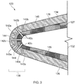
- FIG. 3 shows the same view as Figure 2 .
- Like features between these figures are indicated by reference numerals which are spaced apart by 100.
- the flow splitter 123 differs from the flow splitter 23 in that it comprises a liner 146 which is mounted on a support structure.
- the support structure is the skin 127 of the splitter 123.
- the liner 146 may be simply supported by a support structure in the form of a frame structure (not shown). In this latter case, the liner 146 may be similar to the skin 27 of splitter 23, but may simply be readily removable from a supporting frame structure.
- the liner 146 is secured to the support structure by releasable securing means such that it can be removed and replaced.
- the liner 146 forms part of the body 126 of the splitter 123 and also forms the exterior surface 130 of the splitter 123.
- An internal surface 148 of the liner 146 therefore conforms to the external surface of the skin 127.
- the boreholes 140 are formed in the liner 146 and extend into the liner 146 from the exterior surface 130. As with the boreholes 40, the boreholes 140 may have different types. Some boreholes 140a may extend into the liner 146 to a depth less than the thickness of the liner 146, these will be referred to as 'capped' boreholes 140a. Other boreholes 140b may extend though the entire thickness of the liner 146, which will be known as 'through' boreholes 140b. The boreholes 140 may have various forms as discussed above in relation to the boreholes 40 of splitter 23.
- the skin 127 may also comprise boreholes 40b of the type discussed in relation to Figure 2 above. Some of the boreholes 140b may align with the boreholes 40b to provide combine borehole which extends from the exterior surface 130 of the liner 146 through to the internal cavity 132. As shown in Figure 3 , not all of the boreholes 140b must have a corresponding aligned borehole 40b but, in some cases, each borehole 140b of the liner 146 will be aligned with a corresponding borehole 40b in the skin 127.
- Connecting passages 144 may be formed between the boreholes 140 of the liner 146 in the same manner as connecting passages 44 of splitter 23.
- FIG 4 shows a detailed view of an alternative borehole 40d formed in the exterior surface 30 of the skin 27.
- the borehole 40d operates as a self-contained Helmholtz resonator.
- the borehole 40d comprises two sections having a shared central axis.
- the first cylindrical section 402 is proximate and extends into the exterior surface 30 of the skin and has a first diameter d1.
- the second cylindrical section 404 is in communication with the first section 402 and ultimate the exterior surface 30.
- Second section 404 has a second diameter d2 which is larger than the first diameter d1.
- the first section 402 therefore forms a neck 406, and the second section 404 forms a resonator cavity 408.
- the resonator cavity 408 is in communication with the exterior of the flow splitter via the neck 406.
- a gradual, abrupt, or chamfered transition section may be provided between the neck 406 and the cavity 408, while still maintaining the borehole 40d's function as a Helmholtz resonator.
- the neck and resonator cavity may have shapes other than those of Figure 4 .
- the resonator cavity 408 could be spherical, or could have a hexagonal prismatic shape to tessellate with other resonator cavities 408 of other boreholes 40d also having the same shape.
- Boreholes of the type shown in Figure 4 could also be utilised with other borehole types described herein, and with a liner 146 as shown in Figure 3 .
- the boreholes of the embodiments disclosed herein act to attenuate acoustic waves which interact with the flow splitters 23, 123.
- Both of the splitters 23, 123 can be included in gas turbine engines in order to attenuate ESS interaction tone noise which is reflected off the fan blades or diffracted around the flow splitter.
- the flow splitters 23, 123 are also able to attenuate noise from other sources within the engine which interacts with the flow splitter, such as fan noise or reflected or diffracted outlet guide vane interaction tone noise.
Landscapes
- Engineering & Computer Science (AREA)
- Chemical & Material Sciences (AREA)
- Combustion & Propulsion (AREA)
- Mechanical Engineering (AREA)
- General Engineering & Computer Science (AREA)
- Structures Of Non-Positive Displacement Pumps (AREA)
Abstract
Description
- The present disclosure concerns a flow splitter for a gas turbine engine.
- There are many noise sources in modern gas turbine engines. In particular, noise is produced in a gas turbine engine as the airflow interacts with the engine section stator (ESS). This ESS interaction tone noise can escape around the flow splitter and down the bypass duct, typically by reflection off the fan blades, or by diffraction round the splitter. This ESS interaction noise can then escape from the engine down the bypass duct and adds to the overall level of noise produced by the engine.
- It is generally desirable to reduce the overall level of noise which is produced by a gas turbine engine for reasons such as reducing noise pollution. Therefore, it will be understood that it would be desirable to reduce specific sources of noise within the engine, such as the ESS interaction tone escaping down the bypass duct.
- According to a first aspect there is provided a gas turbine engine comprising:
- a fan;
- an engine core located downstream of the fan so as to receive a first portion of flow from the fan;
- a bypass duct located downstream of the fan and radially outside the engine core, so as to receive a second portion of flow from the fan; and
- a flow splitter defining the location at which the flow from the fan splits into the first and second portions, wherein:
the flow splitter comprises one or more noise-attenuation boreholes formed in an exterior surface of the flow splitter. - The flow splitter may be referred to herein simply as a "splitter" for brevity.
- The boreholes may be for acoustic attenuation of noise, and in particular, noise in or arising from the gas turbine engine.
- One or more of the boreholes may be open or unblocked during use. The boreholes may be free of any fixing device, such as bolts or rivets.
- One or more of the boreholes may be cylindrical boreholes. One or more of the boreholes may be prismatic along their depth. The depth of a borehole may be a distance measured along the borehole from its opening on the exterior surface to an end of the borehole ultimate its opening.
- One or more of the boreholes may be arranged as Helmholtz resonators. One or more of the boreholes may have a first section proximate the exterior surface having a first diameter or cross-sectional area, and a second section ultimate the exterior surface having a second diameter or cross sectional area larger than the first diameter or cross-sectional area. The second section first section may be a neck and the second section may be a resonator cavity. One or more of the boreholes may comprise an abrupt or step increase in cross-sectional area or diameter between the first section and the second section. The first and second sections of the borehole may be in communication with each other.
- One or more of the boreholes may be elongate, may extend into a body of the flow splitter, and may form an opening on the exterior surface.
- A length or depth of one or more of the boreholes may be between around three to ten times a diameter of the borehole.
- One or more of the boreholes may have a constant diameter or cross-sectional area along their depth or length. One or more of the boreholes may have a tapering or increasing diameter along a depth or length of the borehole.
- One or more of the boreholes may have a diameter of less than 2mm, less than 1mm, less than 0.5mm, less than 0.2mm, or less than 0.1mm. One or more of the boreholes may have a diameter between 0.1-1mm or 0.1-0.2mm.
- One or more connecting passages may be formed between one or more of the boreholes. One or more of the connecting passages may connect one part of a borehole to another part of the same borehole. One or more of the connecting passages may be formed between two or more of the boreholes. One or more of the connecting passages may form a flow passage between two or more boreholes.
- One or more of the boreholes may be substantially linear, arcuate, curved, or serpentine.
- The flow splitter may comprise an internal cavity. One or more of the boreholes may extend from the external surface and open into the internal cavity to form a passage between an exterior of the flow splitter and the internal cavity. The flow splitter may have a hollow interior which forms the internal cavity.
- Multiple boreholes may open into the same internal cavity. The flow splitter may comprise a plurality of internal cavities, and one or more boreholes may open into each internal cavity.
- One or more of the boreholes may be configured or angled relative to the external surface to avoid blockage of the boreholes. One or more of the boreholes may extend into the exterior surface of the flow splitter at an oblique angle to the direction of air flow over the flow splitter or to the axial direction of the engine. One or more of the boreholes may be arranged away from the leading edge of the flow splitter to minimise blockage of the boreholes by particular matter in the air flow over the splitter.
- The flow splitter may comprise a support structure and a liner mounted on the support structure which forms the exterior surface of the splitter, wherein the one or more boreholes are formed in the liner.
- The liner may be removably mounted on the support structure. The liner may conform to a shape of the support structure.
- The flow splitter may comprise a leading edge delineating two surfaces and the one or more boreholes may be formed in a region of the flow splitter extending around the leading edge from one surface to the other.
- The one or more boreholes may be empty or free of fixings in an installed configuration of the flow splitter.
- In a second aspect, there is provided gas turbine engine comprising a flow splitter as hereinbefore described.
- An aft end of the flow splitter may be mounted to a support of the gas turbine engine by one or more fasteners. The one or more boreholes may be separated from each and every fastener and empty of any fastener.
- The bypass duct and the engine core may be separated by a casing (which may be referred to as an inner casing, for example to differentiate it from a fan casing which may be referred to as an outer casing), which may be a substantially annular casing. The flow splitter may be provided at the leading edge of such a casing.
- The engine core may comprise at least one of a compressor, a combustor, and a one turbine.
- The skilled person will appreciate that except where mutually exclusive, a feature described in relation to any one of the above aspects may be applied mutatis mutandis to any other aspect. Furthermore except where mutually exclusive, any feature described herein may be applied to any aspect and/or combined with any other feature described herein.
- Embodiments will now be described by way of example only, with reference to the Figures, in which:
-
Figure 1 is a sectional side view of a gas turbine engine; -
Figure 2 is a detailed sectional side view of a first embodiment of a flow splitter according to the present invention; -
Figure 3 is a detailed sectional side view of a second embodiment of a flow splitter according to the present invention; and -
Figure 4 is a detailed view of an alternative borehole according to the present invention. - With reference to
Figure 1 , a gas turbine engine is generally indicated at 10, having a principal androtational axis 11. Theengine 10 comprises, in axial flow series, anair intake 12, apropulsive fan 13, anintermediate pressure compressor 14, a high-pressure compressor 15,combustion equipment 16, a high-pressure turbine 17, anintermediate pressure turbine 18, a low-pressure turbine 19 and anexhaust nozzle 20. Anacelle 21 generally surrounds theengine 10 and defines both theintake 12 and theexhaust nozzle 20. - The
gas turbine engine 10 works in the conventional manner so that air entering theintake 12 is accelerated by thefan 13 past aflow splitter 23, which splits the air into two air flows: a first air flow into theintermediate pressure compressor 14 and a second air flow which passes through abypass duct 22 to provide propulsive thrust. Theintermediate pressure compressor 14 compresses the air flow directed into it before delivering that air to thehigh pressure compressor 15 where further compression takes place. - The compressed air exhausted from the high-
pressure compressor 15 is directed into thecombustion equipment 16 where it is mixed with fuel and the mixture combusted. The resultant hot combustion products then expand through, and thereby drive the high, intermediate and low-pressure turbines nozzle 20 to provide additional propulsive thrust. The high 17, intermediate 18 and low 19 pressure turbines drive respectively thehigh pressure compressor 15,intermediate pressure compressor 14 andfan 13, each by suitable interconnecting shaft. - Other gas turbine engines to which the present disclosure may be applied may have alternative configurations. By way of example such engines may have an alternative number of interconnecting shafts (e.g. two) and/or an alternative number of compressors and/or turbines. Further the engine may comprise a gearbox provided in the drive train from a turbine to a compressor and/or fan.
- A generally tubular (or annular)
inner casing 24 of the engine houses thecompressors combustion equipment 16, and theturbines inner casing 24 is arranged radially inwards of thenacelle 21. The annular gap between thenacelle 21 and theinner casing 24 forms thebypass duct 22. - The flow splitter 23 (which may be referred to simply as a "splitter" for brevity) is arranged at the leading edge of the
inner casing 24 immediately downstream of thefan 13. Theinner casing 24, and thus theflow splitter 23, extends around the entire circumference of theengine 10 within thenacelle 21 and divides the air flow from thefan 13 into two air flows which are separated by theinner casing 24. The air flow passing radially inwards of theflow splitter 23 enters thecompressor 14, is compressed, and passes through the other engine components to produce thrust as discussed above. This air flow radially inside theinner casing 24 will be referred to as the 'core' airflow. - The air flow which passes radially outwards of the
flow splitter 23 and theinner casing 24 passes through theannular bypass duct 22. This air flow will be referred to as the 'bypass' airflow. - Air flow from the
fan 13 which has not travelled downstream past thesplitter 23 will be referred to as the 'combined' airflow. - In order to split the combined air flow efficiently and reduce any negative aerodynamic effects, the
flow splitter 23 is a tapered leading edge of theinner casing 24. In some cases, theflow splitter 23 can be integrally formed with the rest of theinner casing 24, and in other cases, it may be an auxiliary component which is connected to the upstream end of theinner casing 24. Where theflow splitter 23 is a separate component attached to theinner casing 24, it may be connected with bolts, rivets, or the like to enable replacement of theflow splitter 23 if it becomes damaged or faulty during use. - One embodiment of the
flow splitter 23 is shown in more detail inFigure 2 . -
Figure 2 shows the portion of the engine within the dotted boundary inFigure 1 . As will be understood,Figure 2 therefore shows a portion of theflow splitter 23 in cross-section along a radius of theengine 10. - The
flow splitter 23 comprises abody 26 in the form ofskin 27. Theskin 27 forms the tapered shape of thesplitter 23 and is supported by a frame (not shown). Theskin 27 of thesplitter 23, and thus thesplitter 23 itself, has aninternal surface 28 and anexternal surface 30. As theflow splitter 23 is formed by theskin 27, thesplitter 23 is substantially hollow and defines aninternal cavity 32 which is surrounded by theskin 27. - The
external surface 30 of thesplitter 23 comprises two substantially opposingsurfaces outer surface 34 will be referred to asbypass surface 34 as it faces the bypass air flow, and the radiallyinner surface 36 will be referred to as core surface 36 as it faces the core air flow. Aleading edge region 38 of thesplitter 23 extends around the leading edge of thesplitter 23 between the bypass and core surfaces 34, 36, which diverge as they extend downstream. Theflow splitter 23 therefore has a minimum radial width at theleading edge section 38, and gradually increases in radial width as it extends downstream. - A plurality of boreholes 40 are formed in the
exterior surface 30 of theflow splitter 23. The boreholes 40 provide acoustic attenuation of noise within the engine from various sources. The boreholes 40 are relatively small tubular bores which are formed in a pattern about theleading edge section 38 of thesplitter 23. The boreholes 40 may form a borehole array which extends about the entire circumference of theflow splitter 23 around theengine 10. In other examples, the boreholes 40 may be formed in only certain locations of theflow splitter 23 about theengine 10. - The boreholes 40 are elongate and extend into the
body 26 of theflow splitter 23 from theexterior surface 30. The boreholes each form anopening 42 on theexterior surface 30 and extend into theskin 27 by a depth. - Some of the
boreholes 40a extend into theskin 27 by a depth which is less than a thickness of theskin 27, such that theboreholes 40a do not reach theinternal cavity 32 of thesplitter 23. Theseboreholes 40a may be referred to as 'capped'boreholes 40a. -
Other boreholes 40b have a depth equal to the thickness of theskin 27 such that they extend from theexternal surface 30 through theskin 27 and open into theinternal cavity 32. Theseboreholes 40b thus form a passage or conduit between the exterior of theflow splitter 23 and itsinternal cavity 32. Theseboreholes 40b may be referred to as 'through'boreholes 40b. Of course, in some cases, theflow splitter 23 may not comprise aninternal cavity 32, in which case there will be no throughboreholes 40b. Where throughboreholes 40b are provided, theinternal cavity 32 may be used as a resonance damping chamber by utilising Helmholtz resonance. - In some examples, all of the boreholes 40 may be either capped
boreholes 40a, or throughboreholes 40b. In other examples, like that shown inFigure 2 , there may be a mixture of capped and throughboreholes boreholes 40a may have different depths into theskin 27, or may have substantially identical depths into theskin 27. - In some examples, like
splitter 23 ofFigure 2 , one or more connectingpassages 44 may be formed between the boreholes. The connectingpassages 44 may connect boreholes of the same type (i.e. only capped boreholes, or only through boreholes), or may connect boreholes 40 of different types.Connecting passages 44 may, in some examples, connect one part of a borehole 40 to another part of the same borehole 40.Connecting passages 44 may also extend to connect more than two boreholes 40 together, or may be in communication with the exterior of thesplitter 23, or the internal cavity of thesplitter 23. - In
Figure 2 , all of the boreholes 40 are linear boreholes which have a cylindrical shape (i.e. a circular cross sectional area). In other examples, the boreholes 40 may take arched, curved, or serpentine paths through the body of the splitter. The boreholes 40 may have shapes other than cylindrical, such as an ovoid or cuboidal cross sectional area. The boreholes 40 may be prismatic along their depth or length, like those ofFigure 2 , or may have a varying cross-section along their length. - In general, it should be understood that the boreholes can take many forms and that different types of boreholes may be combined in the same splitter. Furthermore, it should also be understood that the number, positioning, and type of the boreholes can be optimised for the particular application and the particular noise to be attenuated. For example, in some situations, it may be advantageous to have particular number of linear through
boreholes 40b. In other examples, it may be advantageous to have a particular mixture of capped and throughboreholes passages 44. - In some examples, boreholes similar to boreholes 40 may also be formed outside of the
leading edge section 38. For example, boreholes might also be formed in the bypass or core surfaces 34, 36. - A second embodiment of a
flow splitter 123 is shown inFigure 3. Figure 3 shows the same view asFigure 2 . Like features between these figures are indicated by reference numerals which are spaced apart by 100. - The
flow splitter 123 differs from theflow splitter 23 in that it comprises aliner 146 which is mounted on a support structure. InFigure 3 , the support structure is theskin 127 of thesplitter 123. In other examples, theliner 146 may be simply supported by a support structure in the form of a frame structure (not shown). In this latter case, theliner 146 may be similar to theskin 27 ofsplitter 23, but may simply be readily removable from a supporting frame structure. Generally, theliner 146 is secured to the support structure by releasable securing means such that it can be removed and replaced. - The
liner 146 forms part of thebody 126 of thesplitter 123 and also forms the exterior surface 130 of thesplitter 123. Aninternal surface 148 of theliner 146 therefore conforms to the external surface of theskin 127. - In
splitter 123, the boreholes 140 are formed in theliner 146 and extend into theliner 146 from the exterior surface 130. As with the boreholes 40, the boreholes 140 may have different types. Someboreholes 140a may extend into theliner 146 to a depth less than the thickness of theliner 146, these will be referred to as 'capped'boreholes 140a.Other boreholes 140b may extend though the entire thickness of theliner 146, which will be known as 'through'boreholes 140b. The boreholes 140 may have various forms as discussed above in relation to the boreholes 40 ofsplitter 23. - As shown in
Figure 3 , in some examples, theskin 127 may also compriseboreholes 40b of the type discussed in relation toFigure 2 above. Some of theboreholes 140b may align with theboreholes 40b to provide combine borehole which extends from the exterior surface 130 of theliner 146 through to theinternal cavity 132. As shown inFigure 3 , not all of theboreholes 140b must have a corresponding alignedborehole 40b but, in some cases, each borehole 140b of theliner 146 will be aligned with acorresponding borehole 40b in theskin 127. -
Connecting passages 144 may be formed between the boreholes 140 of theliner 146 in the same manner as connectingpassages 44 ofsplitter 23. -
Figure 4 shows a detailed view of analternative borehole 40d formed in theexterior surface 30 of theskin 27. Theborehole 40d operates as a self-contained Helmholtz resonator. Theborehole 40d comprises two sections having a shared central axis. The firstcylindrical section 402 is proximate and extends into theexterior surface 30 of the skin and has a first diameter d1. The second cylindrical section 404 is in communication with thefirst section 402 and ultimate theexterior surface 30. Second section 404 has a second diameter d2 which is larger than the first diameter d1. Thefirst section 402 therefore forms aneck 406, and the second section 404 forms aresonator cavity 408. Theresonator cavity 408 is in communication with the exterior of the flow splitter via theneck 406. In theborehole 40d, there is a step change in the diameter of theborehole 40d between theneck 406 and theresonator cavity 408. - It will be understood that a gradual, abrupt, or chamfered transition section may be provided between the
neck 406 and thecavity 408, while still maintaining theborehole 40d's function as a Helmholtz resonator. The neck and resonator cavity may have shapes other than those ofFigure 4 . For example, theresonator cavity 408 could be spherical, or could have a hexagonal prismatic shape to tessellate withother resonator cavities 408 ofother boreholes 40d also having the same shape. Boreholes of the type shown inFigure 4 could also be utilised with other borehole types described herein, and with aliner 146 as shown inFigure 3 . - It will be understood that the boreholes of the embodiments disclosed herein act to attenuate acoustic waves which interact with the
flow splitters splitters flow splitters - It will be understood that the invention is not limited to the embodiments above-described and various modifications and improvements can be made without departing from the concepts described herein. Except where mutually exclusive, any of the features may be employed separately or in combination with any other features and the disclosure extends to and includes all combinations and subcombinations of one or more features described herein.
Claims (15)
- A gas turbine engine comprising:a fan;an engine core located downstream of the fan so as to receive a first portion of flow from the fan;a bypass duct located downstream of the fan and radially outside the engine core, so as to receive a second portion of flow from the fan; anda flow splitter defining the location at which the flow from the fan splits into the first and second portions, wherein:
the flow splitter comprises one or more noise-attenuation boreholes formed in an exterior surface of the flow splitter. - A gas turbine engine as claimed in claim 1, wherein:the boreholes are cylindrical boreholes; and/orone or more of the boreholes is elongate and extends into a body of the flow splitter and forms an opening on the exterior surface; and/ora length of one or more of the boreholes is between around three to ten times a diameter of the borehole; and/orone or more of the boreholes has a diameter of 0.1-1mm.
- A gas turbine engine as claimed in any preceding claim, wherein one or more connecting passages are formed between one or more of the boreholes.
- A gas turbine engine as claimed in claim 3, wherein one or more of the connecting passages are formed between two or more of the boreholes.
- A gas turbine engine as claimed in any preceding claim, wherein one or more of the boreholes are substantially linear.
- A gas turbine engine as claimed in any preceding claim, wherein one or more of the boreholes are arcuate, curved, or serpentine.
- A gas turbine engine as claimed in any preceding claim, wherein the flow splitter comprises an internal cavity, and wherein one or more of the boreholes extends from the external surface and opens into the internal cavity to form a passage between an exterior of the flow splitter and the internal cavity.
- A gas turbine engine as claimed in any preceding claim, wherein one or more of the boreholes comprises a first section proximate the exterior surface having a first cross-sectional area, and a second section ultimate the exterior surface having a second cross-sectional area larger than the first cross-sectional area.
- A gas turbine engine as claimed in claim 8, wherein the one or more boreholes comprises an abrupt or step change in cross-sectional area between the first section and the second section
- A gas turbine engine as claimed in any preceding claim, comprising a support structure and a liner mounted on the support structure which forms the exterior surface of the splitter, wherein the one or more boreholes are formed in the liner.
- A gas turbine engine as claimed in claim 10, wherein the liner is removably mounted on the support structure.
- A gas turbine engine as claimed in any preceding claim, wherein the flow splitter comprises a leading edge delineating two surfaces and wherein the one or more boreholes are formed in a region of the flow splitter extending around the leading edge from one surface to the other.
- A gas turbine engine as claimed in any preceding claim, wherein the one or more boreholes are empty.
- A gas turbine engine according to any one of the preceding claims, wherein:the bypass duct and the engine core are separated by a substantially annular casing; andthe flow splitter is provided at the leading edge of the casing.
- A gas turbine engine according to any one of the preceding claims, wherein the engine core comprises at least one compressor, a combustor, and at least one turbine.
Applications Claiming Priority (1)
| Application Number | Priority Date | Filing Date | Title |
|---|---|---|---|
| GBGB1705734.0A GB201705734D0 (en) | 2017-04-10 | 2017-04-10 | Flow splitter |
Publications (2)
| Publication Number | Publication Date |
|---|---|
| EP3388642A1 true EP3388642A1 (en) | 2018-10-17 |
| EP3388642B1 EP3388642B1 (en) | 2021-01-27 |
Family
ID=58744834
Family Applications (1)
| Application Number | Title | Priority Date | Filing Date |
|---|---|---|---|
| EP18161157.5A Active EP3388642B1 (en) | 2017-04-10 | 2018-03-12 | Gas turbine engine with flow splitter having noise-attenuating boreholes |
Country Status (3)
| Country | Link |
|---|---|
| US (1) | US10858994B2 (en) |
| EP (1) | EP3388642B1 (en) |
| GB (1) | GB201705734D0 (en) |
Families Citing this family (3)
| Publication number | Priority date | Publication date | Assignee | Title |
|---|---|---|---|---|
| FR3078431A1 (en) * | 2018-02-28 | 2019-08-30 | Airbus Operations | SOUNDPROOFING COATING COMPRISING AN ALVEOLAR STRUCTURE WITH CURVED CELLS SHAPED ON EITHER OF THE SAME INTERNAL WALL |
| FR3095230B1 (en) | 2019-04-16 | 2021-03-19 | Safran Aircraft Engines | DEFROST DEVICE |
| EP4123151B1 (en) * | 2021-07-20 | 2024-09-04 | Rolls-Royce plc | Variable pitch fan thrust reverser |
Citations (6)
| Publication number | Priority date | Publication date | Assignee | Title |
|---|---|---|---|---|
| US20080000717A1 (en) * | 2006-06-29 | 2008-01-03 | Patrick William P | Anechoic visco-thermal liner |
| US20090165995A1 (en) * | 2007-12-27 | 2009-07-02 | Techspace Aero | Air-oil heat exchanger placed at the location of the air separator nose of a turbojet, and a turbojet including such an air-oil heat exchanger |
| US20100206664A1 (en) * | 2007-07-12 | 2010-08-19 | Rolls-Royce Plc | Acoustic panel |
| EP2977601A1 (en) * | 2014-07-21 | 2016-01-27 | United Technologies Corporation | Noise attenuating acoustic panel |
| US9514734B1 (en) * | 2011-06-30 | 2016-12-06 | The United States Of America As Represented By The Administrator Of National Aeronautics And Space Administration | Acoustic liners for turbine engines |
| EP3112269A1 (en) * | 2015-06-30 | 2017-01-04 | Rolls-Royce plc | Aircraft engine nacelle |
Family Cites Families (15)
| Publication number | Priority date | Publication date | Assignee | Title |
|---|---|---|---|---|
| US4371132A (en) * | 1980-01-11 | 1983-02-01 | Rolls Royce Limited | Reversible thrust ducted fan propulsion unit |
| US6439840B1 (en) | 2000-11-30 | 2002-08-27 | Pratt & Whitney Canada Corp. | Bypass duct fan noise reduction assembly |
| US6561760B2 (en) * | 2001-08-17 | 2003-05-13 | General Electric Company | Booster compressor deicer |
| US20070012508A1 (en) * | 2005-07-13 | 2007-01-18 | Demers Christopher G | Impact resistance acoustic treatment |
| EP1801389B1 (en) | 2005-12-23 | 2008-08-20 | Techspace aero | Acoustic isolation of the stator of a low pressure compressor |
| US20080216300A1 (en) * | 2007-03-06 | 2008-09-11 | United Technologies Corporation | Splitter fairing repair |
| FR2965859B1 (en) | 2010-10-07 | 2012-11-02 | Snecma | DEVICE FOR ACOUSTICALLY PROCESSING NOISE EMITTED BY A TURBOJETACTOR |
| EP2932068B1 (en) | 2012-12-13 | 2017-11-15 | United Technologies Corporation | Gas turbine engine with cooling scheme for drive gear system and pitch control |
| BE1022482B1 (en) * | 2014-10-21 | 2016-05-02 | Techspace Aero S.A. | PLASMA DEFROSTING SEPARATION SPOUT FOR AXIAL TURBOMACHINE COMPRESSOR |
| US20160230993A1 (en) * | 2015-02-10 | 2016-08-11 | United Technologies Corporation | Combustor liner effusion cooling holes |
| CA2933884A1 (en) * | 2015-06-30 | 2016-12-30 | Rolls-Royce Corporation | Combustor tile |
| FR3047042B1 (en) * | 2016-01-22 | 2018-02-16 | Safran Aircraft Engines | DEVICE FOR DEFROSTING A SEPARATION SPOUT AND INPUT DIRECTION GUIDES OF AERONAUTICAL TURBOMACHINE |
| FR3051016B1 (en) * | 2016-05-09 | 2020-03-13 | Safran Aircraft Engines | DEVICE FOR DEFROSTING A SPOUT FOR AERONAUTICAL TURBOMACHINE |
| BE1024684B1 (en) * | 2016-10-21 | 2018-05-25 | Safran Aero Boosters S.A. | AXIAL TURBOMACHINE COMPRESSOR DEGIVER |
| US11092017B2 (en) * | 2018-11-09 | 2021-08-17 | Raytheon Technologies Corporation | Mini core passage with protrusion |
-
2017
- 2017-04-10 GB GBGB1705734.0A patent/GB201705734D0/en not_active Ceased
-
2018
- 2018-03-12 EP EP18161157.5A patent/EP3388642B1/en active Active
- 2018-04-09 US US15/948,205 patent/US10858994B2/en active Active
Patent Citations (6)
| Publication number | Priority date | Publication date | Assignee | Title |
|---|---|---|---|---|
| US20080000717A1 (en) * | 2006-06-29 | 2008-01-03 | Patrick William P | Anechoic visco-thermal liner |
| US20100206664A1 (en) * | 2007-07-12 | 2010-08-19 | Rolls-Royce Plc | Acoustic panel |
| US20090165995A1 (en) * | 2007-12-27 | 2009-07-02 | Techspace Aero | Air-oil heat exchanger placed at the location of the air separator nose of a turbojet, and a turbojet including such an air-oil heat exchanger |
| US9514734B1 (en) * | 2011-06-30 | 2016-12-06 | The United States Of America As Represented By The Administrator Of National Aeronautics And Space Administration | Acoustic liners for turbine engines |
| EP2977601A1 (en) * | 2014-07-21 | 2016-01-27 | United Technologies Corporation | Noise attenuating acoustic panel |
| EP3112269A1 (en) * | 2015-06-30 | 2017-01-04 | Rolls-Royce plc | Aircraft engine nacelle |
Also Published As
| Publication number | Publication date |
|---|---|
| EP3388642B1 (en) | 2021-01-27 |
| US10858994B2 (en) | 2020-12-08 |
| US20180291808A1 (en) | 2018-10-11 |
| GB201705734D0 (en) | 2017-05-24 |
Similar Documents
| Publication | Publication Date | Title |
|---|---|---|
| EP3187712B1 (en) | Nacelle short inlet | |
| EP3187722B1 (en) | Nacelle short inlet for fan blade removal | |
| US20090191047A1 (en) | System for reducing compressor noise | |
| US10513980B2 (en) | Gas turbine engine arrangement | |
| EP1944468B1 (en) | A turbine blade | |
| US10683806B2 (en) | Protected core inlet with reduced capture area | |
| CN110475947A (en) | Pressure Sensor Assemblies for Turbine Engines | |
| US10858994B2 (en) | Gas turbine flow splitter having noise attenuation boreholes | |
| US9494043B1 (en) | Turbine blade having contoured tip shroud | |
| EP3896251A1 (en) | Composite reinforced rotor | |
| US8403629B2 (en) | Stator for a jet engine, a jet engine comprising such a stator, and an aircraft comprising the jet engine | |
| EP1722069A1 (en) | Combustion turbine engine | |
| EP3536902B1 (en) | Gas turbine engine component | |
| US20200049022A1 (en) | Gas turbine engine mounting arrangement | |
| US10502062B2 (en) | Integrally bladed rotor having axial arm and pocket | |
| US10767486B2 (en) | Mistuned concentric airfoil assembly and method of mistuning same | |
| EP3467320A1 (en) | A bladed disk | |
| US12228053B1 (en) | Turbofan engine including integrated pylon and fan outlet guide vane with noise reduction features | |
| US20240229738A1 (en) | Aircraft engine exhaust mixer | |
| US20250075632A1 (en) | Containment engine case with local features and outer surface reinforcement section | |
| US20250075635A1 (en) | Containment engine case with local features and inner surface reinforcement section | |
| CA2992784A1 (en) | Gas turbine engine arrangement | |
| CN115127115A (en) | Component assembly for a combustion section of a gas turbine engine | |
| EP3301288A1 (en) | Accessory gearbox for a gas turbine engine |
Legal Events
| Date | Code | Title | Description |
|---|---|---|---|
| PUAI | Public reference made under article 153(3) epc to a published international application that has entered the european phase |
Free format text: ORIGINAL CODE: 0009012 |
|
| STAA | Information on the status of an ep patent application or granted ep patent |
Free format text: STATUS: THE APPLICATION HAS BEEN PUBLISHED |
|
| AK | Designated contracting states |
Kind code of ref document: A1 Designated state(s): AL AT BE BG CH CY CZ DE DK EE ES FI FR GB GR HR HU IE IS IT LI LT LU LV MC MK MT NL NO PL PT RO RS SE SI SK SM TR |
|
| AX | Request for extension of the european patent |
Extension state: BA ME |
|
| STAA | Information on the status of an ep patent application or granted ep patent |
Free format text: STATUS: REQUEST FOR EXAMINATION WAS MADE |
|
| 17P | Request for examination filed |
Effective date: 20190409 |
|
| RBV | Designated contracting states (corrected) |
Designated state(s): AL AT BE BG CH CY CZ DE DK EE ES FI FR GB GR HR HU IE IS IT LI LT LU LV MC MK MT NL NO PL PT RO RS SE SI SK SM TR |
|
| STAA | Information on the status of an ep patent application or granted ep patent |
Free format text: STATUS: EXAMINATION IS IN PROGRESS |
|
| RAP1 | Party data changed (applicant data changed or rights of an application transferred) |
Owner name: ROLLS-ROYCE PLC |
|
| 17Q | First examination report despatched |
Effective date: 20200131 |
|
| RIC1 | Information provided on ipc code assigned before grant |
Ipc: F02C 7/045 20060101ALI20200717BHEP Ipc: F02K 3/06 20060101ALI20200717BHEP Ipc: F01D 25/24 20060101AFI20200717BHEP |
|
| GRAP | Despatch of communication of intention to grant a patent |
Free format text: ORIGINAL CODE: EPIDOSNIGR1 |
|
| STAA | Information on the status of an ep patent application or granted ep patent |
Free format text: STATUS: GRANT OF PATENT IS INTENDED |
|
| INTG | Intention to grant announced |
Effective date: 20200914 |
|
| GRAS | Grant fee paid |
Free format text: ORIGINAL CODE: EPIDOSNIGR3 |
|
| GRAA | (expected) grant |
Free format text: ORIGINAL CODE: 0009210 |
|
| STAA | Information on the status of an ep patent application or granted ep patent |
Free format text: STATUS: THE PATENT HAS BEEN GRANTED |
|
| AK | Designated contracting states |
Kind code of ref document: B1 Designated state(s): AL AT BE BG CH CY CZ DE DK EE ES FI FR GB GR HR HU IE IS IT LI LT LU LV MC MK MT NL NO PL PT RO RS SE SI SK SM TR |
|
| REG | Reference to a national code |
Ref country code: GB Ref legal event code: FG4D |
|
| REG | Reference to a national code |
Ref country code: CH Ref legal event code: EP |
|
| REG | Reference to a national code |
Ref country code: AT Ref legal event code: REF Ref document number: 1358530 Country of ref document: AT Kind code of ref document: T Effective date: 20210215 |
|
| REG | Reference to a national code |
Ref country code: IE Ref legal event code: FG4D |
|
| REG | Reference to a national code |
Ref country code: DE Ref legal event code: R096 Ref document number: 602018012157 Country of ref document: DE |
|
| REG | Reference to a national code |
Ref country code: NL Ref legal event code: MP Effective date: 20210127 |
|
| REG | Reference to a national code |
Ref country code: LT Ref legal event code: MG9D |
|
| REG | Reference to a national code |
Ref country code: AT Ref legal event code: MK05 Ref document number: 1358530 Country of ref document: AT Kind code of ref document: T Effective date: 20210127 |
|
| PG25 | Lapsed in a contracting state [announced via postgrant information from national office to epo] |
Ref country code: GR Free format text: LAPSE BECAUSE OF FAILURE TO SUBMIT A TRANSLATION OF THE DESCRIPTION OR TO PAY THE FEE WITHIN THE PRESCRIBED TIME-LIMIT Effective date: 20210428 Ref country code: FI Free format text: LAPSE BECAUSE OF FAILURE TO SUBMIT A TRANSLATION OF THE DESCRIPTION OR TO PAY THE FEE WITHIN THE PRESCRIBED TIME-LIMIT Effective date: 20210127 Ref country code: HR Free format text: LAPSE BECAUSE OF FAILURE TO SUBMIT A TRANSLATION OF THE DESCRIPTION OR TO PAY THE FEE WITHIN THE PRESCRIBED TIME-LIMIT Effective date: 20210127 Ref country code: NO Free format text: LAPSE BECAUSE OF FAILURE TO SUBMIT A TRANSLATION OF THE DESCRIPTION OR TO PAY THE FEE WITHIN THE PRESCRIBED TIME-LIMIT Effective date: 20210427 Ref country code: PT Free format text: LAPSE BECAUSE OF FAILURE TO SUBMIT A TRANSLATION OF THE DESCRIPTION OR TO PAY THE FEE WITHIN THE PRESCRIBED TIME-LIMIT Effective date: 20210527 Ref country code: BG Free format text: LAPSE BECAUSE OF FAILURE TO SUBMIT A TRANSLATION OF THE DESCRIPTION OR TO PAY THE FEE WITHIN THE PRESCRIBED TIME-LIMIT Effective date: 20210427 Ref country code: LT Free format text: LAPSE BECAUSE OF FAILURE TO SUBMIT A TRANSLATION OF THE DESCRIPTION OR TO PAY THE FEE WITHIN THE PRESCRIBED TIME-LIMIT Effective date: 20210127 |
|
| PG25 | Lapsed in a contracting state [announced via postgrant information from national office to epo] |
Ref country code: SE Free format text: LAPSE BECAUSE OF FAILURE TO SUBMIT A TRANSLATION OF THE DESCRIPTION OR TO PAY THE FEE WITHIN THE PRESCRIBED TIME-LIMIT Effective date: 20210127 Ref country code: AT Free format text: LAPSE BECAUSE OF FAILURE TO SUBMIT A TRANSLATION OF THE DESCRIPTION OR TO PAY THE FEE WITHIN THE PRESCRIBED TIME-LIMIT Effective date: 20210127 Ref country code: PL Free format text: LAPSE BECAUSE OF FAILURE TO SUBMIT A TRANSLATION OF THE DESCRIPTION OR TO PAY THE FEE WITHIN THE PRESCRIBED TIME-LIMIT Effective date: 20210127 Ref country code: RS Free format text: LAPSE BECAUSE OF FAILURE TO SUBMIT A TRANSLATION OF THE DESCRIPTION OR TO PAY THE FEE WITHIN THE PRESCRIBED TIME-LIMIT Effective date: 20210127 Ref country code: LV Free format text: LAPSE BECAUSE OF FAILURE TO SUBMIT A TRANSLATION OF THE DESCRIPTION OR TO PAY THE FEE WITHIN THE PRESCRIBED TIME-LIMIT Effective date: 20210127 |
|
| PG25 | Lapsed in a contracting state [announced via postgrant information from national office to epo] |
Ref country code: IS Free format text: LAPSE BECAUSE OF FAILURE TO SUBMIT A TRANSLATION OF THE DESCRIPTION OR TO PAY THE FEE WITHIN THE PRESCRIBED TIME-LIMIT Effective date: 20210527 |
|
| REG | Reference to a national code |
Ref country code: DE Ref legal event code: R097 Ref document number: 602018012157 Country of ref document: DE |
|
| PG25 | Lapsed in a contracting state [announced via postgrant information from national office to epo] |
Ref country code: MC Free format text: LAPSE BECAUSE OF FAILURE TO SUBMIT A TRANSLATION OF THE DESCRIPTION OR TO PAY THE FEE WITHIN THE PRESCRIBED TIME-LIMIT Effective date: 20210127 Ref country code: CZ Free format text: LAPSE BECAUSE OF FAILURE TO SUBMIT A TRANSLATION OF THE DESCRIPTION OR TO PAY THE FEE WITHIN THE PRESCRIBED TIME-LIMIT Effective date: 20210127 Ref country code: EE Free format text: LAPSE BECAUSE OF FAILURE TO SUBMIT A TRANSLATION OF THE DESCRIPTION OR TO PAY THE FEE WITHIN THE PRESCRIBED TIME-LIMIT Effective date: 20210127 Ref country code: SM Free format text: LAPSE BECAUSE OF FAILURE TO SUBMIT A TRANSLATION OF THE DESCRIPTION OR TO PAY THE FEE WITHIN THE PRESCRIBED TIME-LIMIT Effective date: 20210127 |
|
| REG | Reference to a national code |
Ref country code: CH Ref legal event code: PL |
|
| PG25 | Lapsed in a contracting state [announced via postgrant information from national office to epo] |
Ref country code: DK Free format text: LAPSE BECAUSE OF FAILURE TO SUBMIT A TRANSLATION OF THE DESCRIPTION OR TO PAY THE FEE WITHIN THE PRESCRIBED TIME-LIMIT Effective date: 20210127 Ref country code: SK Free format text: LAPSE BECAUSE OF FAILURE TO SUBMIT A TRANSLATION OF THE DESCRIPTION OR TO PAY THE FEE WITHIN THE PRESCRIBED TIME-LIMIT Effective date: 20210127 Ref country code: RO Free format text: LAPSE BECAUSE OF FAILURE TO SUBMIT A TRANSLATION OF THE DESCRIPTION OR TO PAY THE FEE WITHIN THE PRESCRIBED TIME-LIMIT Effective date: 20210127 |
|
| PLBE | No opposition filed within time limit |
Free format text: ORIGINAL CODE: 0009261 |
|
| STAA | Information on the status of an ep patent application or granted ep patent |
Free format text: STATUS: NO OPPOSITION FILED WITHIN TIME LIMIT |
|
| REG | Reference to a national code |
Ref country code: BE Ref legal event code: MM Effective date: 20210331 |
|
| 26N | No opposition filed |
Effective date: 20211028 |
|
| PG25 | Lapsed in a contracting state [announced via postgrant information from national office to epo] |
Ref country code: ES Free format text: LAPSE BECAUSE OF FAILURE TO SUBMIT A TRANSLATION OF THE DESCRIPTION OR TO PAY THE FEE WITHIN THE PRESCRIBED TIME-LIMIT Effective date: 20210127 Ref country code: AL Free format text: LAPSE BECAUSE OF FAILURE TO SUBMIT A TRANSLATION OF THE DESCRIPTION OR TO PAY THE FEE WITHIN THE PRESCRIBED TIME-LIMIT Effective date: 20210127 Ref country code: CH Free format text: LAPSE BECAUSE OF NON-PAYMENT OF DUE FEES Effective date: 20210331 Ref country code: IE Free format text: LAPSE BECAUSE OF NON-PAYMENT OF DUE FEES Effective date: 20210312 Ref country code: LI Free format text: LAPSE BECAUSE OF NON-PAYMENT OF DUE FEES Effective date: 20210331 Ref country code: LU Free format text: LAPSE BECAUSE OF NON-PAYMENT OF DUE FEES Effective date: 20210312 |
|
| PG25 | Lapsed in a contracting state [announced via postgrant information from national office to epo] |
Ref country code: SI Free format text: LAPSE BECAUSE OF FAILURE TO SUBMIT A TRANSLATION OF THE DESCRIPTION OR TO PAY THE FEE WITHIN THE PRESCRIBED TIME-LIMIT Effective date: 20210127 |
|
| PG25 | Lapsed in a contracting state [announced via postgrant information from national office to epo] |
Ref country code: IT Free format text: LAPSE BECAUSE OF FAILURE TO SUBMIT A TRANSLATION OF THE DESCRIPTION OR TO PAY THE FEE WITHIN THE PRESCRIBED TIME-LIMIT Effective date: 20210127 |
|
| PG25 | Lapsed in a contracting state [announced via postgrant information from national office to epo] |
Ref country code: IS Free format text: LAPSE BECAUSE OF FAILURE TO SUBMIT A TRANSLATION OF THE DESCRIPTION OR TO PAY THE FEE WITHIN THE PRESCRIBED TIME-LIMIT Effective date: 20210527 |
|
| PG25 | Lapsed in a contracting state [announced via postgrant information from national office to epo] |
Ref country code: BE Free format text: LAPSE BECAUSE OF NON-PAYMENT OF DUE FEES Effective date: 20210331 |
|
| PG25 | Lapsed in a contracting state [announced via postgrant information from national office to epo] |
Ref country code: NL Free format text: LAPSE BECAUSE OF NON-PAYMENT OF DUE FEES Effective date: 20210127 Ref country code: CY Free format text: LAPSE BECAUSE OF FAILURE TO SUBMIT A TRANSLATION OF THE DESCRIPTION OR TO PAY THE FEE WITHIN THE PRESCRIBED TIME-LIMIT Effective date: 20210127 |
|
| P01 | Opt-out of the competence of the unified patent court (upc) registered |
Effective date: 20230528 |
|
| PG25 | Lapsed in a contracting state [announced via postgrant information from national office to epo] |
Ref country code: HU Free format text: LAPSE BECAUSE OF FAILURE TO SUBMIT A TRANSLATION OF THE DESCRIPTION OR TO PAY THE FEE WITHIN THE PRESCRIBED TIME-LIMIT; INVALID AB INITIO Effective date: 20180312 |
|
| PG25 | Lapsed in a contracting state [announced via postgrant information from national office to epo] |
Ref country code: MK Free format text: LAPSE BECAUSE OF FAILURE TO SUBMIT A TRANSLATION OF THE DESCRIPTION OR TO PAY THE FEE WITHIN THE PRESCRIBED TIME-LIMIT Effective date: 20210127 |
|
| PG25 | Lapsed in a contracting state [announced via postgrant information from national office to epo] |
Ref country code: MT Free format text: LAPSE BECAUSE OF FAILURE TO SUBMIT A TRANSLATION OF THE DESCRIPTION OR TO PAY THE FEE WITHIN THE PRESCRIBED TIME-LIMIT Effective date: 20210127 |
|
| PG25 | Lapsed in a contracting state [announced via postgrant information from national office to epo] |
Ref country code: TR Free format text: LAPSE BECAUSE OF FAILURE TO SUBMIT A TRANSLATION OF THE DESCRIPTION OR TO PAY THE FEE WITHIN THE PRESCRIBED TIME-LIMIT Effective date: 20210127 |
|
| PGFP | Annual fee paid to national office [announced via postgrant information from national office to epo] |
Ref country code: GB Payment date: 20260323 Year of fee payment: 9 |
|
| PGFP | Annual fee paid to national office [announced via postgrant information from national office to epo] |
Ref country code: DE Payment date: 20260320 Year of fee payment: 9 |
|
| PGFP | Annual fee paid to national office [announced via postgrant information from national office to epo] |
Ref country code: FR Payment date: 20260323 Year of fee payment: 9 |