EP3388634A1 - Gas turbine blade assembly having retainer assembling structure, and gas turbine having same - Google Patents
Gas turbine blade assembly having retainer assembling structure, and gas turbine having same Download PDFInfo
- Publication number
- EP3388634A1 EP3388634A1 EP17192813.8A EP17192813A EP3388634A1 EP 3388634 A1 EP3388634 A1 EP 3388634A1 EP 17192813 A EP17192813 A EP 17192813A EP 3388634 A1 EP3388634 A1 EP 3388634A1
- Authority
- EP
- European Patent Office
- Prior art keywords
- retainer
- gas turbine
- turbine blade
- blade assembly
- insertion hole
- Prior art date
- Legal status (The legal status is an assumption and is not a legal conclusion. Google has not performed a legal analysis and makes no representation as to the accuracy of the status listed.)
- Granted
Links
Images



Classifications
-
- F—MECHANICAL ENGINEERING; LIGHTING; HEATING; WEAPONS; BLASTING
- F01—MACHINES OR ENGINES IN GENERAL; ENGINE PLANTS IN GENERAL; STEAM ENGINES
- F01D—NON-POSITIVE DISPLACEMENT MACHINES OR ENGINES, e.g. STEAM TURBINES
- F01D5/00—Blades; Blade-carrying members; Heating, heat-insulating, cooling or antivibration means on the blades or the members
- F01D5/30—Fixing blades to rotors; Blade roots ; Blade spacers
- F01D5/3007—Fixing blades to rotors; Blade roots ; Blade spacers of axial insertion type
- F01D5/3015—Fixing blades to rotors; Blade roots ; Blade spacers of axial insertion type with side plates
-
- F—MECHANICAL ENGINEERING; LIGHTING; HEATING; WEAPONS; BLASTING
- F01—MACHINES OR ENGINES IN GENERAL; ENGINE PLANTS IN GENERAL; STEAM ENGINES
- F01D—NON-POSITIVE DISPLACEMENT MACHINES OR ENGINES, e.g. STEAM TURBINES
- F01D5/00—Blades; Blade-carrying members; Heating, heat-insulating, cooling or antivibration means on the blades or the members
- F01D5/30—Fixing blades to rotors; Blade roots ; Blade spacers
- F01D5/32—Locking, e.g. by final locking blades or keys
- F01D5/326—Locking of axial insertion type blades by other means
-
- F—MECHANICAL ENGINEERING; LIGHTING; HEATING; WEAPONS; BLASTING
- F01—MACHINES OR ENGINES IN GENERAL; ENGINE PLANTS IN GENERAL; STEAM ENGINES
- F01D—NON-POSITIVE DISPLACEMENT MACHINES OR ENGINES, e.g. STEAM TURBINES
- F01D5/00—Blades; Blade-carrying members; Heating, heat-insulating, cooling or antivibration means on the blades or the members
- F01D5/30—Fixing blades to rotors; Blade roots ; Blade spacers
-
- F—MECHANICAL ENGINEERING; LIGHTING; HEATING; WEAPONS; BLASTING
- F01—MACHINES OR ENGINES IN GENERAL; ENGINE PLANTS IN GENERAL; STEAM ENGINES
- F01D—NON-POSITIVE DISPLACEMENT MACHINES OR ENGINES, e.g. STEAM TURBINES
- F01D11/00—Preventing or minimising internal leakage of working-fluid, e.g. between stages
-
- F—MECHANICAL ENGINEERING; LIGHTING; HEATING; WEAPONS; BLASTING
- F01—MACHINES OR ENGINES IN GENERAL; ENGINE PLANTS IN GENERAL; STEAM ENGINES
- F01D—NON-POSITIVE DISPLACEMENT MACHINES OR ENGINES, e.g. STEAM TURBINES
- F01D11/00—Preventing or minimising internal leakage of working-fluid, e.g. between stages
- F01D11/005—Sealing means between non relatively rotating elements
-
- F—MECHANICAL ENGINEERING; LIGHTING; HEATING; WEAPONS; BLASTING
- F01—MACHINES OR ENGINES IN GENERAL; ENGINE PLANTS IN GENERAL; STEAM ENGINES
- F01D—NON-POSITIVE DISPLACEMENT MACHINES OR ENGINES, e.g. STEAM TURBINES
- F01D5/00—Blades; Blade-carrying members; Heating, heat-insulating, cooling or antivibration means on the blades or the members
- F01D5/30—Fixing blades to rotors; Blade roots ; Blade spacers
- F01D5/3007—Fixing blades to rotors; Blade roots ; Blade spacers of axial insertion type
-
- F—MECHANICAL ENGINEERING; LIGHTING; HEATING; WEAPONS; BLASTING
- F01—MACHINES OR ENGINES IN GENERAL; ENGINE PLANTS IN GENERAL; STEAM ENGINES
- F01D—NON-POSITIVE DISPLACEMENT MACHINES OR ENGINES, e.g. STEAM TURBINES
- F01D5/00—Blades; Blade-carrying members; Heating, heat-insulating, cooling or antivibration means on the blades or the members
- F01D5/30—Fixing blades to rotors; Blade roots ; Blade spacers
- F01D5/32—Locking, e.g. by final locking blades or keys
-
- F—MECHANICAL ENGINEERING; LIGHTING; HEATING; WEAPONS; BLASTING
- F01—MACHINES OR ENGINES IN GENERAL; ENGINE PLANTS IN GENERAL; STEAM ENGINES
- F01D—NON-POSITIVE DISPLACEMENT MACHINES OR ENGINES, e.g. STEAM TURBINES
- F01D11/00—Preventing or minimising internal leakage of working-fluid, e.g. between stages
- F01D11/005—Sealing means between non relatively rotating elements
- F01D11/006—Sealing the gap between rotor blades or blades and rotor
-
- F—MECHANICAL ENGINEERING; LIGHTING; HEATING; WEAPONS; BLASTING
- F01—MACHINES OR ENGINES IN GENERAL; ENGINE PLANTS IN GENERAL; STEAM ENGINES
- F01D—NON-POSITIVE DISPLACEMENT MACHINES OR ENGINES, e.g. STEAM TURBINES
- F01D5/00—Blades; Blade-carrying members; Heating, heat-insulating, cooling or antivibration means on the blades or the members
- F01D5/02—Blade-carrying members, e.g. rotors
-
- F—MECHANICAL ENGINEERING; LIGHTING; HEATING; WEAPONS; BLASTING
- F01—MACHINES OR ENGINES IN GENERAL; ENGINE PLANTS IN GENERAL; STEAM ENGINES
- F01D—NON-POSITIVE DISPLACEMENT MACHINES OR ENGINES, e.g. STEAM TURBINES
- F01D5/00—Blades; Blade-carrying members; Heating, heat-insulating, cooling or antivibration means on the blades or the members
- F01D5/12—Blades
-
- F—MECHANICAL ENGINEERING; LIGHTING; HEATING; WEAPONS; BLASTING
- F05—INDEXING SCHEMES RELATING TO ENGINES OR PUMPS IN VARIOUS SUBCLASSES OF CLASSES F01-F04
- F05D—INDEXING SCHEME FOR ASPECTS RELATING TO NON-POSITIVE-DISPLACEMENT MACHINES OR ENGINES, GAS-TURBINES OR JET-PROPULSION PLANTS
- F05D2220/00—Application
- F05D2220/30—Application in turbines
- F05D2220/32—Application in turbines in gas turbines
-
- F—MECHANICAL ENGINEERING; LIGHTING; HEATING; WEAPONS; BLASTING
- F05—INDEXING SCHEMES RELATING TO ENGINES OR PUMPS IN VARIOUS SUBCLASSES OF CLASSES F01-F04
- F05D—INDEXING SCHEME FOR ASPECTS RELATING TO NON-POSITIVE-DISPLACEMENT MACHINES OR ENGINES, GAS-TURBINES OR JET-PROPULSION PLANTS
- F05D2260/00—Function
- F05D2260/30—Retaining components in desired mutual position
Definitions
- the present disclosure relates generally to a gas turbine blade assembly having retainer assembling structure, and a gas turbine having the same. More particularly, the present disclosure relates to a gas turbine blade assembly having a structure capable of being easily disassembled and assembled and achieving sealing, and a gas turbine having the same.
- a turbine is a mechanical device that obtains torque by impulsive force or reaction force using flow of compressible fluid such as steam or gas. It is called as a steam turbine when steam is used and a gas turbine when combustion gas is used.
- a thermodynamic cycle of the gas turbine is the Brayton Cycle, which is as follows: a compressor for sucking and boosting air from the atmosphere and supplying combustion air to a combustor; the combustor for mixing and combusting the introduced compressed air with fuel to produce a combustion gas of high energy; and a turbine for converting the high temperature and high pressure combustion gas from the combustor into mechanical energy when the combustion gas expands to apply the impulsive and reaction force to rotating blades of the turbine.
- the mechanical energy obtained from the turbine is supplied to the compressor (approximately 60% of the total turbine power) required to compress the air and the remainder is used to drive a generator to produce power.
- the operation principle of the gas turbine is the following four steps: compression, heating, expansion, and heat dissipation. That is, the air in the atmosphere is sucked first, compressed by the compressor, then sent to the combustor to generate high temperature and high pressure gas to operate the turbine, and the exhaust gas is discharged to the atmosphere.
- a retainer is provided adjacent to a blade and a rotating disk to form a sealing and flow path for the cooling air flowing from the rotating disk.
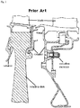
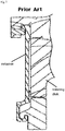
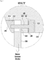
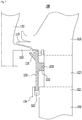
- FIGS. 1 and 2 are sectional views partially showing a gas turbine blade assembly provided with a retainer according to the related art.
- the retainer is locked to the blade or to a side of the rotating disk by force fitting or by using a coupling member.
- the retainer according to the related art is problematic in that it requires a very complicated structure to form the cooling gas sealing and the flow path, so it is not easy to manufacture and install.
- a gas turbine blade assembly as an assembly provided with a plurality of gas turbine blades on an outer circumferential surface of a rotating disk along a circumferential direction to be spaced apart from each other at predetermined intervals, the gas turbine blade assembly including: a retainer insertion hole provided in a blade-fixing end, and depressed by a predetermined depth to correspond to a lower end of a retainer; a retainer coupler provided at a lower end of each of the gas turbine blades, and depressed by a predetermined depth to correspond to an upper end of the retainer; and a coupling member coupled at a location adjacent to the retainer coupler to couple the retainer and each of the gas turbine blades together.
- each of the gas turbine blades may be mounted to a dovetail slot provided on the outer circumferential surface of the rotating disk along the circumferential direction, and the gas turbine blades may be aligned in an axial direction by the retainer.
- the rotating disk may be provided with a protruding structure protruding by a predetermined length at a side thereof, and the protruding structure may be provided with the retainer insertion hole at an upper surface thereof.
- the protruding structure may be provided along the circumferential direction of the rotating disk, and may be in an annular shape in a plan view.
- the retainer insertion hole may be provided with a bearing surface on an inner surface thereof to be in surface contact with the retainer.
- the lower end of the retainer may be spaced apart from a bottom surface of the retainer insertion hole at a predetermined distance, and the depth of the retainer coupler may be equal to or less than the distance between the lower end of the retainer and the bottom surface of the retainer insertion hole.
- the gas turbine blade assembly may further include a coupling member insertion hole provided at a location adjacent to the retainer coupler at the lower end of each of the gas turbine blades, and depressed to correspond to the coupling member.
- a slot groove in a shape corresponding to an outer surface of the coupling member may be provided between the coupling member insertion hole and the retainer coupler.
- the slot groove may be provided in a direction parallel to an extension direction of the retainer.
- the coupling member may be in a bolt structure, with a bolt head thereof inserted into the coupling member insertion hole, and with a threaded part thereof protruding by a predetermined length in a direction toward the retainer coupler to be engaged with the upper end of the retainer.
- the threaded part of the coupling member may be engaged with a nut to couple the coupling member and the retainer together, and an outer surface of the nut may be formed as curved surface continuous with an outer surface of the lower end of each of the gas turbine blades.
- each of the gas turbine blades may be provided with a sealing protrusion protruding by a predetermined length in a direction toward a neighboring gas turbine blade.
- the upper end of the retainer may be provided with an auxiliary sealing protrusion protruding by a predetermined length to correspond to the sealing protrusion.
- a side surface of the retainer may be provided with a support protrusion extending in a direction toward the lower end of each of the gas turbine blades and having a contact surface corresponding to a side surface of each of the gas turbine blades, with a sealing wire mounted to the contact surface of the support protrusion.
- a gas turbine having the gas turbine blade assembly.
- the gas turbine includes a blade assembly provided with a plurality of gas turbine blades on an outer circumferential surface of a rotating disk along a circumferential direction to be spaced apart from each other at predetermined intervals, wherein the blade assembly includes: a retainer insertion hole provided in a blade-fixing end, and depressed by a predetermined depth to correspond to a lower end of a retainer; a retainer coupler provided at a lower end of each of the gas turbine blades, and depressed by a predetermined depth to correspond to an upper end of the retainer; and a coupling member coupled at a location adjacent to the retainer coupler to couple the retainer and each of the gas turbine blades together.
- the rotating disk may be provided with a protruding structure protruding by a predetermined length at a side thereof, and the protruding structure may be provided with the retainer insertion hole at an upper surface thereof.
- the protruding structure may be provided along the circumferential direction of the rotating disk, and may be in an annular shape in plan view.
- the lower end of the retainer may be spaced apart from a bottom surface of the retainer insertion hole at a predetermined distance, and the depth of the retainer coupler may be equal to or less than the distance between the lower end of the retainer and the bottom surface of the retainer insertion hole.
- the gas turbine blade assembly may further include a coupling member insertion hole provided at a location adjacent to the retainer coupler at the lower end of each of the gas turbine blades, and depressed to correspond to the coupling member.
- an exemplary gas turbine blade assembly of the present disclosure provided with a retainer insertion hole, a retainer coupler, and a coupling member having predetermined structures, it is possible to provide a gas turbine blade assembly having a structure capable of being easily disassembled and assembled and may achieve complete sealing, and a gas turbine having the same.
- an exemplary gas turbine blade assembly of the present disclosure that includes a protruding structure having a predetermined structure is provided at a side of a rotating disk, with the protruding structure provided with the retainer insertion hole at an upper surface thereof, it is possible to facilitate easy assembly and disassembly and possible to achieve complete sealing.
- an exemplary gas turbine blade assembly of the present disclosure that includes a retainer insertion hole provided with a bearing surface on an inner surface thereof to be in surface contact with the retainer, it may be possible to achieve complete sealing of the gas turbine blade, the rotating disk, and the retainer.
- the lower end of the retainer is spaced apart from a bottom surface of the retainer insertion hole at a predetermined distance, and the depth of the retainer coupler is equal to or less than the distance between the lower end of the retainer and the bottom surface of the retainer insertion hole, assembly and disassembly of the retainer may be performed more easily than the related art.
- an exemplary gas turbine blade assembly of the present disclosure that includes a coupling member insertion hole, a coupling member, and a retainer coupler having predetermined structures, it is possible to easily assemble and disassemble the retainer, and possible to achieve a stable coupling structure.
- an exemplary gas turbine blade assembly of the present disclosure that includes a slot groove in a predetermined shape provided between the coupling member insertion hole and the retainer coupler, and the retainer and the gas turbine blade are coupled together after the coupling member is mounted by using the slot groove, it is possible to perform easy assembly, and possible to achieve a stable coupling structure.
- an exemplary gas turbine blade assembly of the present disclosure that includes a sealing protrusion, an auxiliary sealing protrusion, a support protrusion, and a sealing wire having predetermined structures, it is possible to provide a structure capable of facilitating easy assembly and disassembly and may achieve complete sealing.
- an exemplary gas turbine of the present disclosure that includes a gas turbine blade assembly having a predetermined structure, it is possible to provide a gas turbine having a structure capable of being easily disassembled and assembled and may achieve complete sealing.
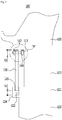
- FIG. 3 is a sectional view partially showing a gas turbine blade assembly according to an embodiment of the present disclosure.
- a gas turbine blade assembly 100 which is as an assembly provided with a plurality of gas turbine blades 110 on an outer circumferential surface of a rotating disk 120 along a circumferential direction to be spaced apart from each other at predetermined intervals, includes a retainer insertion hole 122, a retainer coupler 112, and a coupling member 140 having predetermined structures, whereby it is possible to provide a gas turbine blade assembly having a structure capable of being easily disassembled and assembled and may achieve complete sealing, and a gas turbine having the same.
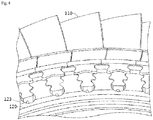
- FIG. 4 is a partial enlarged view showing a rotating disk provided with a dovetail slot, to which the gas turbine blade according to the embodiment of the present disclosure is mounted;
- FIG. 5 is an enlarged view of area A of FIG. 3 ;
- FIG. 6 is a partial enlarged view showing a slot groove of a retainer shown in FIG. 3 .
- the retainer insertion hole 122 may be provided at a side of an upper end 121 of the rotating disk, and may be depressed by a predetermined depth to correspond to a lower end of a retainer 130.
- the rotating disk 120 may be provided with a protruding structure 124 protruding by a predetermined length at a side thereof, and the protruding structure 124 may be provided with the retainer insertion hole 122 at an upper surface thereof.
- the protruding structure 124 may be provided along the circumferential direction of the rotating disk 120, and may be in an annular shape in a plan view.
- the retainer insertion hole 122 may be provided with a bearing surface 125 on an inner surface thereof to be in surface contact with the retainer 130.
- the retainer coupler 112 may be provided at a lower end of each of the gas turbine blades 110, and may be depressed by a predetermined depth to correspond to an upper end of the retainer 130.
- the lower end of the retainer 130 is spaced apart from a bottom surface of the retainer insertion hole 122 at a predetermined distance d1, and the depth d2 of the retainer coupler 112 is equal to or less than the distance between the lower end of the retainer 130 and the bottom surface of the retainer insertion hole 122.
- the coupling member 140 may be coupled at a location adjacent to the retainer coupler 112 to couple the retainer 130 and each of the gas turbine blades 110 together.
- each of the gas turbine blades 110 may be mounted to a dovetail slot 123 provided on the outer circumferential surface of the rotating disk 120 along the circumferential direction.
- the gas turbine blades 110 may be aligned in an axial direction by the retainer 130.
- a coupling member insertion hole 113 may be provided at a location adjacent to the retainer coupler 112 at the lower end of each of the gas turbine blades 110.
- the coupling member insertion hole 113 be in a shape corresponding to the coupling member 140.
- a slot groove 114 in a shape corresponding to an outer surface of the coupling member 140 may be provided between the coupling member insertion hole 113 and the retainer coupler 112.
- the slot groove 114 be provided in a direction parallel to an extension direction of the retainer 130.
- the coupling member 140 can be easily coupled or separated using the slot groove 114, so that assembly and disassembly of the retainer can be more easily induced.
- the coupling member 140 which is in a bolt structure, may include a bolt head 141, and a threaded part 142.
- the bolt head 141 of the coupling member 140 be inserted into the coupling member insertion hole, and the threaded part 142 of the coupling member protrude by a predetermined length in a direction toward the retainer coupler 112 to be engaged with the upper end of the retainer 130.
- the threaded part 142 of the coupling member 140 may be engaged with a nut 143 to couple the coupling member 140 and the retainer 130 together.
- an outer surface of the nut 143 is formed as a curved surface 145 continuous with an outer surface of the lower end of each of the gas turbine blades 110.
- FIG. 7 is a sectional view partially showing a gas turbine blade assembly according to another embodiment of the present disclosure.
- the gas turbine blade assembly 100 may further include a sealing protrusion 115 that is provided at the lower end of each of the gas turbine blades 110 and protrudes by a predetermined length in a direction toward a neighboring gas turbine blade 110.
- the upper end of the retainer 130 may be provided with an auxiliary sealing protrusion 131 protruding by a predetermined length to correspond to the sealing protrusion 115.
- a side surface of the retainer 130 may be provided with a support protrusion 132 extending in a direction toward the lower end of each of the gas turbine blades 110 and having a contact surface corresponding to a side surface of each of the gas turbine blades 110.
- a sealing wire 133 be mounted to the contact surface of the support protrusion 132.
- the gas turbine blade assembly 100 of the present disclosure since it is provided with the sealing protrusion 115, the auxiliary sealing protrusion 131, the support protrusion 132, and the sealing wire 133 having predetermined structures, it is possible to provide a structure capable of facilitating easy assembly and disassembly and may achieve complete sealing.
- the present disclosure further provides a gas turbine having the above described gas turbine blade assembly 100, in which, as shown in FIG. 8 , it is possible to provide a gas turbine having a structure capable of being easily disassembled and assembled and achieving complete sealing.
- Figure 8A illustrates the gas turbine blade assembly 100 in an assembled state.
- Figure 8B illustrates the removal of the nut 143 from the coupling member 140 and the displacement of the retainer 130 downwardly into the insertion hole 122.
- Figure 8C illustrates the removal of the coupling member 140 and the retainer 130.
- Figure 8D illustrates the gas turbine blade assembly 100 in a disassembled state. While the present disclosure has been described in conjunction with exemplary embodiments thereof, it is to be understood that the present description does not limit the present disclosure to those exemplary embodiments. On the contrary, the present disclosure covers not only the exemplary embodiments, but also various alternatives, modifications, equivalents and other embodiments that may be included within the scope of the present invention as defined by the appended claims.
Landscapes
- Engineering & Computer Science (AREA)
- Mechanical Engineering (AREA)
- General Engineering & Computer Science (AREA)
- Turbine Rotor Nozzle Sealing (AREA)
- Gasket Seals (AREA)
Abstract
Description
- The present application claims priority to Korean Patent Application No.
10-2017-0047337, filed April 12, 2017 - The present disclosure relates generally to a gas turbine blade assembly having retainer assembling structure, and a gas turbine having the same. More particularly, the present disclosure relates to a gas turbine blade assembly having a structure capable of being easily disassembled and assembled and achieving sealing, and a gas turbine having the same.
- Generally, a turbine is a mechanical device that obtains torque by impulsive force or reaction force using flow of compressible fluid such as steam or gas. It is called as a steam turbine when steam is used and a gas turbine when combustion gas is used.
- A thermodynamic cycle of the gas turbine is the Brayton Cycle, which is as follows: a compressor for sucking and boosting air from the atmosphere and supplying combustion air to a combustor; the combustor for mixing and combusting the introduced compressed air with fuel to produce a combustion gas of high energy; and a turbine for converting the high temperature and high pressure combustion gas from the combustor into mechanical energy when the combustion gas expands to apply the impulsive and reaction force to rotating blades of the turbine.
- The mechanical energy obtained from the turbine is supplied to the compressor (approximately 60% of the total turbine power) required to compress the air and the remainder is used to drive a generator to produce power.
- The operation principle of the gas turbine is the following four steps: compression, heating, expansion, and heat dissipation. That is, the air in the atmosphere is sucked first, compressed by the compressor, then sent to the combustor to generate high temperature and high pressure gas to operate the turbine, and the exhaust gas is discharged to the atmosphere.
- Among components of the conventional gas turbine, a retainer is provided adjacent to a blade and a rotating disk to form a sealing and flow path for the cooling air flowing from the rotating disk.
-
FIGS. 1 and2 are sectional views partially showing a gas turbine blade assembly provided with a retainer according to the related art. - According to the related art, various methods are used to assemble the retainer.
- According to the related art, as shown in
FIGS. 1 and2 , the retainer is locked to the blade or to a side of the rotating disk by force fitting or by using a coupling member. - However, the above method is problematic in that a large number of members to be prepared for assembly are required, and the assembling process and the disassembling process are very complicated, whereby work efficiency is remarkably low.
- The retainer according to the related art is problematic in that it requires a very complicated structure to form the cooling gas sealing and the flow path, so it is not easy to manufacture and install.
- Accordingly, a new technique for a gas turbine blade assembly is needed.
- The foregoing is intended merely to aid in the understanding of the background of the present disclosure, and does not mean that the present disclosure falls within the purview of the background art.
- The object is solved by the features of the independent claims. Preferred embodiments are given in the dependent claims.
- According to some aspects of the present disclosure, there is provided a gas turbine blade assembly, as an assembly provided with a plurality of gas turbine blades on an outer circumferential surface of a rotating disk along a circumferential direction to be spaced apart from each other at predetermined intervals, the gas turbine blade assembly including: a retainer insertion hole provided in a blade-fixing end, and depressed by a predetermined depth to correspond to a lower end of a retainer; a retainer coupler provided at a lower end of each of the gas turbine blades, and depressed by a predetermined depth to correspond to an upper end of the retainer; and a coupling member coupled at a location adjacent to the retainer coupler to couple the retainer and each of the gas turbine blades together.
- In an embodiment of the present disclosure, each of the gas turbine blades may be mounted to a dovetail slot provided on the outer circumferential surface of the rotating disk along the circumferential direction, and the gas turbine blades may be aligned in an axial direction by the retainer.
- In an embodiment of the present disclosure, the rotating disk may be provided with a protruding structure protruding by a predetermined length at a side thereof, and the protruding structure may be provided with the retainer insertion hole at an upper surface thereof.
- In the above case, the protruding structure may be provided along the circumferential direction of the rotating disk, and may be in an annular shape in a plan view.
- In an embodiment of the present disclosure, the retainer insertion hole may be provided with a bearing surface on an inner surface thereof to be in surface contact with the retainer.
- In an embodiment of the present disclosure, the lower end of the retainer may be spaced apart from a bottom surface of the retainer insertion hole at a predetermined distance, and the depth of the retainer coupler may be equal to or less than the distance between the lower end of the retainer and the bottom surface of the retainer insertion hole.
- In an embodiment of the present disclosure, the gas turbine blade assembly may further include a coupling member insertion hole provided at a location adjacent to the retainer coupler at the lower end of each of the gas turbine blades, and depressed to correspond to the coupling member.
- In the above case, a slot groove in a shape corresponding to an outer surface of the coupling member may be provided between the coupling member insertion hole and the retainer coupler.
- Further, the slot groove may be provided in a direction parallel to an extension direction of the retainer.
- In an embodiment of the present disclosure, the coupling member may be in a bolt structure, with a bolt head thereof inserted into the coupling member insertion hole, and with a threaded part thereof protruding by a predetermined length in a direction toward the retainer coupler to be engaged with the upper end of the retainer.
- Further, the threaded part of the coupling member may be engaged with a nut to couple the coupling member and the retainer together, and an outer surface of the nut may be formed as curved surface continuous with an outer surface of the lower end of each of the gas turbine blades.
- In an embodiment of the present disclosure, the lower end of each of the gas turbine blades may be provided with a sealing protrusion protruding by a predetermined length in a direction toward a neighboring gas turbine blade.
- In an embodiment of the present disclosure, the upper end of the retainer may be provided with an auxiliary sealing protrusion protruding by a predetermined length to correspond to the sealing protrusion.
- In an embodiment of the present disclosure, a side surface of the retainer may be provided with a support protrusion extending in a direction toward the lower end of each of the gas turbine blades and having a contact surface corresponding to a side surface of each of the gas turbine blades, with a sealing wire mounted to the contact surface of the support protrusion.
- Further, according to some aspects of the present disclosure, there is provided a gas turbine having the gas turbine blade assembly. The gas turbine includes a blade assembly provided with a plurality of gas turbine blades on an outer circumferential surface of a rotating disk along a circumferential direction to be spaced apart from each other at predetermined intervals, wherein the blade assembly includes: a retainer insertion hole provided in a blade-fixing end, and depressed by a predetermined depth to correspond to a lower end of a retainer; a retainer coupler provided at a lower end of each of the gas turbine blades, and depressed by a predetermined depth to correspond to an upper end of the retainer; and a coupling member coupled at a location adjacent to the retainer coupler to couple the retainer and each of the gas turbine blades together.
- In an embodiment of the present disclosure, the rotating disk may be provided with a protruding structure protruding by a predetermined length at a side thereof, and the protruding structure may be provided with the retainer insertion hole at an upper surface thereof.
- In an embodiment of the present disclosure, the protruding structure may be provided along the circumferential direction of the rotating disk, and may be in an annular shape in plan view.
- In an embodiment of the present disclosure, the lower end of the retainer may be spaced apart from a bottom surface of the retainer insertion hole at a predetermined distance, and the depth of the retainer coupler may be equal to or less than the distance between the lower end of the retainer and the bottom surface of the retainer insertion hole.
- In an embodiment of the present disclosure, the gas turbine blade assembly may further include a coupling member insertion hole provided at a location adjacent to the retainer coupler at the lower end of each of the gas turbine blades, and depressed to correspond to the coupling member.
- As described above, according to an exemplary gas turbine blade assembly of the present disclosure provided with a retainer insertion hole, a retainer coupler, and a coupling member having predetermined structures, it is possible to provide a gas turbine blade assembly having a structure capable of being easily disassembled and assembled and may achieve complete sealing, and a gas turbine having the same.
- Further, according to an exemplary gas turbine blade assembly of the present disclosure that includes a protruding structure having a predetermined structure is provided at a side of a rotating disk, with the protruding structure provided with the retainer insertion hole at an upper surface thereof, it is possible to facilitate easy assembly and disassembly and possible to achieve complete sealing.
- Further, according to an exemplary gas turbine blade assembly of the present disclosure that includes a retainer insertion hole provided with a bearing surface on an inner surface thereof to be in surface contact with the retainer, it may be possible to achieve complete sealing of the gas turbine blade, the rotating disk, and the retainer.
- Further, according to an exemplary gas turbine blade assembly of the present disclosure in which the lower end of the retainer is spaced apart from a bottom surface of the retainer insertion hole at a predetermined distance, and the depth of the retainer coupler is equal to or less than the distance between the lower end of the retainer and the bottom surface of the retainer insertion hole, assembly and disassembly of the retainer may be performed more easily than the related art.
- Further, according to an exemplary gas turbine blade assembly of the present disclosure that includes a coupling member insertion hole, a coupling member, and a retainer coupler having predetermined structures, it is possible to easily assemble and disassemble the retainer, and possible to achieve a stable coupling structure.
- Further, according to an exemplary gas turbine blade assembly of the present disclosure that includes a slot groove in a predetermined shape provided between the coupling member insertion hole and the retainer coupler, and the retainer and the gas turbine blade are coupled together after the coupling member is mounted by using the slot groove, it is possible to perform easy assembly, and possible to achieve a stable coupling structure.
- Further, according to an exemplary gas turbine blade assembly of the present disclosure in which the gas turbine blade is locked by using a nut formed with a curved surface continuous with an outer surface of the lower end of each of the gas turbine blades, it is possible to achieve a stable coupling structure.
- Further, according to an exemplary gas turbine blade assembly of the present disclosure that includes a sealing protrusion, an auxiliary sealing protrusion, a support protrusion, and a sealing wire having predetermined structures, it is possible to provide a structure capable of facilitating easy assembly and disassembly and may achieve complete sealing.
- Further, according to an exemplary gas turbine of the present disclosure that includes a gas turbine blade assembly having a predetermined structure, it is possible to provide a gas turbine having a structure capable of being easily disassembled and assembled and may achieve complete sealing.
- The above and other objects, features and other advantages of the present disclosure will be more clearly understood from the following detailed description when taken in conjunction with the accompanying drawings, in which:
-
FIG. 1 is a sectional view partially showing a gas turbine blade assembly provided with a retainer according to the related art; -
FIG. 2 is a sectional view partially showing the gas turbine blade assembly provided with the retainer according to the related art; -
FIG. 3 is a sectional view partially showing a gas turbine blade assembly according to an embodiment of the present disclosure; -
FIG. 4 is a partial enlarged view showing a rotating disk provided with a dovetail slot, to which the gas turbine blade according to the embodiment of the present disclosure is mounted; -
FIG. 5 is an enlarged view of area A ofFIG. 3 ; -
FIG. 6 is a partial enlarged view showing a slot groove of a retainer shown inFIG. 3 ; -
FIG. 7 is a sectional view partially showing a gas turbine blade assembly according to another embodiment of the present disclosure; -
FIG. 8A is schematic view showing disassembly of the retainer of the gas turbine blade according to an embodiment of the present disclosure; -
FIG. 8B is schematic view showing disassembly of the retainer of the gas turbine blade according to an embodiment of the present disclosure; -
FIG. 8C is schematic view showing disassembly of the retainer of the gas turbine blade according to an embodiment of the present disclosure; and -
FIG. 8D is schematic view showing disassembly of the retainer of the gas turbine blade according to an embodiment of the present disclosure. - Reference will now be made in detail to preferred embodiments of the present disclosure with reference to the accompanying drawings. Before describing, it will be further understood that terms, such as those defined in commonly used dictionaries, should be interpreted as having a meaning that is consistent with their meaning in the context of the relevant art and the present disclosure, and will not be interpreted in an idealized or overly formal sense unless expressly so defined herein.
- Throughout the specification, when a member is "on" another member, it includes not only when a member is in contact with another member, but also when there is another member between the two members. It will be further understood that the terms "comprise", "include", "have", etc. when used in this specification, specify the presence of stated features, integers, steps, operations, elements, components, and/or combinations of them but do not preclude the presence or addition of one or more other features, integers, steps, operations, elements, components, and/or combinations thereof.
-
FIG. 3 is a sectional view partially showing a gas turbine blade assembly according to an embodiment of the present disclosure. - Referring to
FIG. 3 , a gasturbine blade assembly 100 according to the embodiment, which is as an assembly provided with a plurality ofgas turbine blades 110 on an outer circumferential surface of arotating disk 120 along a circumferential direction to be spaced apart from each other at predetermined intervals, includes aretainer insertion hole 122, aretainer coupler 112, and acoupling member 140 having predetermined structures, whereby it is possible to provide a gas turbine blade assembly having a structure capable of being easily disassembled and assembled and may achieve complete sealing, and a gas turbine having the same. - Hereinbelow, each component of the gas
turbine blade assembly 100 will be described in detail, with reference to the accompanying drawings. -
FIG. 4 is a partial enlarged view showing a rotating disk provided with a dovetail slot, to which the gas turbine blade according to the embodiment of the present disclosure is mounted;FIG. 5 is an enlarged view of area A ofFIG. 3 ; andFIG. 6 is a partial enlarged view showing a slot groove of a retainer shown inFIG. 3 . - Referring to the above drawings along with
FIG. 3 , theretainer insertion hole 122 according to the embodiment may be provided at a side of anupper end 121 of the rotating disk, and may be depressed by a predetermined depth to correspond to a lower end of aretainer 130. - In some cases, as shown in
FIG. 3 , therotating disk 120 may be provided with a protrudingstructure 124 protruding by a predetermined length at a side thereof, and the protrudingstructure 124 may be provided with theretainer insertion hole 122 at an upper surface thereof. - Here, the protruding
structure 124 may be provided along the circumferential direction of therotating disk 120, and may be in an annular shape in a plan view. - Further, the
retainer insertion hole 122 may be provided with abearing surface 125 on an inner surface thereof to be in surface contact with theretainer 130. - The
retainer coupler 112 may be provided at a lower end of each of thegas turbine blades 110, and may be depressed by a predetermined depth to correspond to an upper end of theretainer 130. - Preferably, the lower end of the
retainer 130 is spaced apart from a bottom surface of theretainer insertion hole 122 at a predetermined distance d1, and the depth d2 of theretainer coupler 112 is equal to or less than the distance between the lower end of theretainer 130 and the bottom surface of theretainer insertion hole 122. - In this case, as shown in
FIG. 8 , it is very easy to disassemble or assemble theretainer 130. Further, thecoupling member 140 may be coupled at a location adjacent to theretainer coupler 112 to couple theretainer 130 and each of thegas turbine blades 110 together. - As shown in
FIG. 4 , each of thegas turbine blades 110 according to the embodiment may be mounted to adovetail slot 123 provided on the outer circumferential surface of therotating disk 120 along the circumferential direction. Here, thegas turbine blades 110 may be aligned in an axial direction by theretainer 130. - In some cases, as shown in
FIGS. 3 and5 , a couplingmember insertion hole 113 may be provided at a location adjacent to theretainer coupler 112 at the lower end of each of thegas turbine blades 110. Here, it is preferred that the couplingmember insertion hole 113 be in a shape corresponding to thecoupling member 140. - Further, as shown in
FIGS. 5 and6 , aslot groove 114 in a shape corresponding to an outer surface of thecoupling member 140 may be provided between the couplingmember insertion hole 113 and theretainer coupler 112. Here, it is preferred that theslot groove 114 be provided in a direction parallel to an extension direction of theretainer 130. - In this case, the
coupling member 140 can be easily coupled or separated using theslot groove 114, so that assembly and disassembly of the retainer can be more easily induced. - Meanwhile, as shown in
FIG. 5 , thecoupling member 140 according to the embodiment, which is in a bolt structure, may include abolt head 141, and a threadedpart 142. - To be more specific, it is preferred that the
bolt head 141 of thecoupling member 140 be inserted into the coupling member insertion hole, and the threadedpart 142 of the coupling member protrude by a predetermined length in a direction toward theretainer coupler 112 to be engaged with the upper end of theretainer 130. - Further, the threaded
part 142 of thecoupling member 140 may be engaged with anut 143 to couple thecoupling member 140 and theretainer 130 together. - In some cases, as shown in
FIG. 5 , an outer surface of thenut 143 is formed as acurved surface 145 continuous with an outer surface of the lower end of each of thegas turbine blades 110. -
FIG. 7 is a sectional view partially showing a gas turbine blade assembly according to another embodiment of the present disclosure. - Referring to
FIG. 7 , the gasturbine blade assembly 100 according to the embodiment may further include a sealingprotrusion 115 that is provided at the lower end of each of thegas turbine blades 110 and protrudes by a predetermined length in a direction toward a neighboringgas turbine blade 110. - Further, as shown in
FIG. 7 , the upper end of theretainer 130 may be provided with anauxiliary sealing protrusion 131 protruding by a predetermined length to correspond to the sealingprotrusion 115. - In some cases, a side surface of the
retainer 130 may be provided with asupport protrusion 132 extending in a direction toward the lower end of each of thegas turbine blades 110 and having a contact surface corresponding to a side surface of each of thegas turbine blades 110. - Here, it is preferred that a
sealing wire 133 be mounted to the contact surface of thesupport protrusion 132. - Accordingly, according to the gas
turbine blade assembly 100 of the present disclosure, since it is provided with the sealingprotrusion 115, theauxiliary sealing protrusion 131, thesupport protrusion 132, and thesealing wire 133 having predetermined structures, it is possible to provide a structure capable of facilitating easy assembly and disassembly and may achieve complete sealing. - The present disclosure further provides a gas turbine having the above described gas
turbine blade assembly 100, in which, as shown inFIG. 8 , it is possible to provide a gas turbine having a structure capable of being easily disassembled and assembled and achieving complete sealing. -
Figure 8A illustrates the gasturbine blade assembly 100 in an assembled state.Figure 8B illustrates the removal of thenut 143 from thecoupling member 140 and the displacement of theretainer 130 downwardly into theinsertion hole 122.Figure 8C illustrates the removal of thecoupling member 140 and theretainer 130.Figure 8D illustrates the gasturbine blade assembly 100 in a disassembled state. While the present disclosure has been described in conjunction with exemplary embodiments thereof, it is to be understood that the present description does not limit the present disclosure to those exemplary embodiments. On the contrary, the present disclosure covers not only the exemplary embodiments, but also various alternatives, modifications, equivalents and other embodiments that may be included within the scope of the present invention as defined by the appended claims. - In other words, the present disclosure is not limited to the exemplary embodiments nor to the above description, and those skilled in the art will appreciate that various modifications, additions, and substitutions are possible, without departing from the scope of the disclosure.
Claims (15)
- A gas turbine blade assembly (100), comprising:a turbine blade (110) including a retainer coupler (112) provided a first distance from a first end;a rotating disk (120) including a blade-fixing end and a retainer insertion holed (122) defined in the blade-fixing end, a depth of the retainer insertion hole (122) being at least the first distance;a retainer (130) sized to be disposed in the retainer insertion hole (122); anda coupling member (140) disposed at a location proximal to the retainer coupler(112) to couple the retainer (130) and the (110) together.
- The gas turbine blade assembly (100) of claim 1, wherein
the rotating disk (120) includes a dovetail slot (123) on an outer circumferential surface,
the turbine blade (110) is operable to mount to the dovetail slot (123), and
the turbine blade (110) is aligned in an axial direction by the retainer (130). - The gas turbine blade assembly (100) of claim 1 or 2, wherein the rotating disk (120) includes a protruding structure (124) at an upper surface providing the retainer insertion hole (122)
- The gas turbine blade assembly (100) of claim 3, wherein the protruding structure (124) is disposed along a circumferential direction of the rotating disk (120), and is in an annular shape in a plan view.
- The gas turbine blade assembly (100) as claimed in any one of the preceding claims, wherein an inner surface of the retainer insertion hole (122) includes a bearing surface (125) operable to contact the retainer (130).
- The gas turbine blade assembly (100) as claimed in any one of the preceding claims, whereina lower end of the retainer (130) is spaced apart from a bottom surface of the retainer insertion hole (122), anda depth of the retainer coupler (112) is equal to or less than the distance between the lower end of the retainer (130) and the bottom surface of the retainer insertion hole (122).
- The gas turbine blade assembly (100) as claimed in any one of the preceding claims, further comprising a coupling member insertion hole (113) defined at a location adjacent to the coupling member (140) at the first end of the turbine blade (110).
- The gas turbine blade assembly (100) of claim 7, wherein a slot groove in a shape corresponding to an outer surface of the coupling member (140) is defined between the coupling member insertion hole (113) and the retainer coupler (112).
- The gas turbine blade assembly (100) of claim 8, wherein the slot groove is disposed in a direction parallel to an extension direction of the retainer (130).
- The gas turbine blade assembly (100) of claim 7, wherein the coupling member (140) includes a bolt, a head of the bolt head being disposed proximal to the coupling member insertion hole (113), and a threaded part of the bolt protruding in a direction toward the retainer coupler (112) to engage with the retainer (130).
- The gas turbine blade assembly (100) of claim 10, whereinthe threaded part of the coupling member (140) is operable to engage with a nut to couple the coupling member (140) and the retainer (130) together, andan outer surface of the nut includes a curved surface corresponding to an outer surface of an end of the turbine blade (110).
- The gas turbine blade assembly (100) as claimed in any one of the preceding claims, wherein the first end of the turbine blade (110) includes a sealing protrusion that protrudes toward a neighboring gas turbine blade (110).
- The gas turbine blade assembly (100) of claim 12, wherein the retainer (130) includes an auxiliary sealing protrusion that protrudes by a length to corresponding to a length of the sealing protrusion.
- The gas turbine blade assembly (100) as claimed in any one of the preceding claims, whereina side surface of the retainer (130) includes a support protrusion extending in a direction toward the first end of the turbine blade (110),the retainer (130) includes and a contact surface corresponding to a side surface of the turbine blade (110), anda sealing wire is disposed on the contact surface of the support protrusion.
- A gas turbine comprising:a blade assembly (100) including a plurality of gas turbine blades (110) on an outer circumferential surface of a rotating disk (120) along a circumferential direction and spaced apart from each other, wherein the blade assembly (100) includes:a retainer coupler (112) provided a first distance from a first end of one of the turbine blades (110);a retainer insertion hole (122) defined in a blade-fixing end of the rotating disk (120), a depth of the retainer insertion hole (122) being at least the first distance;a retainer (130) sized to be disposed in the retainer insertion hole (122); anda coupling member (140) disposed at a location proximal to the retainer coupler (112) to couple the retainer (130) and the turbine blade (110) together.
Applications Claiming Priority (1)
| Application Number | Priority Date | Filing Date | Title |
|---|---|---|---|
| KR1020170047337A KR101878360B1 (en) | 2017-04-12 | 2017-04-12 | Gas Turbine Blade Assembly Having Retainer Assembling Structure, And Gas Turbine Having The Same |
Publications (2)
| Publication Number | Publication Date |
|---|---|
| EP3388634A1 true EP3388634A1 (en) | 2018-10-17 |
| EP3388634B1 EP3388634B1 (en) | 2019-12-25 |
Family
ID=59966609
Family Applications (1)
| Application Number | Title | Priority Date | Filing Date |
|---|---|---|---|
| EP17192813.8A Active EP3388634B1 (en) | 2017-04-12 | 2017-09-25 | Gas turbine blade assembly having retainer assembling structure, and gas turbine having same |
Country Status (4)
| Country | Link |
|---|---|
| US (1) | US20180298766A1 (en) |
| EP (1) | EP3388634B1 (en) |
| JP (1) | JP6459134B2 (en) |
| KR (1) | KR101878360B1 (en) |
Families Citing this family (5)
| Publication number | Priority date | Publication date | Assignee | Title |
|---|---|---|---|---|
| KR101882109B1 (en) * | 2016-12-23 | 2018-07-25 | 두산중공업 주식회사 | Gas turbine |
| KR102142141B1 (en) | 2018-08-17 | 2020-08-06 | 두산중공업 주식회사 | Turbine, gas turbine, and disassembling method of turbine blade |
| KR102134812B1 (en) | 2018-08-17 | 2020-07-16 | 두산중공업 주식회사 | Turbine, gas turbine including the same, assembling method of turbine, and disassembling method of turbine |
| KR102478172B1 (en) * | 2021-02-02 | 2022-12-14 | 두산에너빌리티 주식회사 | Rotary machine, gas turbine including the same, assembling method of the same |
| US12168940B1 (en) * | 2023-09-08 | 2024-12-17 | Pratt & Whitney Canada Corp. | Radial transition fit between primary and secondary parts of a rotor assembly |
Citations (5)
| Publication number | Priority date | Publication date | Assignee | Title |
|---|---|---|---|---|
| US3853425A (en) * | 1973-09-07 | 1974-12-10 | Westinghouse Electric Corp | Turbine rotor blade cooling and sealing system |
| GB2268979A (en) * | 1992-07-22 | 1994-01-26 | Snecma | Sealing and blade retaining arrangement for a turbomachine rotor. |
| US20040062643A1 (en) * | 2002-09-30 | 2004-04-01 | General Electric Company | Turbomachinery blade retention system |
| EP2662533A2 (en) * | 2012-05-07 | 2013-11-13 | General Electric Company | Cover segment for blade mounting region, corresponding system and method of mounting |
| KR20170047337A (en) | 2014-08-26 | 2017-05-04 | 이마비오떼끄 | Method for characterizing a sample by mass spectrometry imaging |
Family Cites Families (14)
| Publication number | Priority date | Publication date | Assignee | Title |
|---|---|---|---|---|
| US3266770A (en) * | 1961-12-22 | 1966-08-16 | Gen Electric | Turbomachine rotor assembly |
| US3501249A (en) * | 1968-06-24 | 1970-03-17 | Westinghouse Electric Corp | Side plates for turbine blades |
| US4021138A (en) * | 1975-11-03 | 1977-05-03 | Westinghouse Electric Corporation | Rotor disk, blade, and seal plate assembly for cooled turbine rotor blades |
| FR2502690B1 (en) * | 1981-03-27 | 1985-09-13 | Snecma | DEVICE FOR LOCKING BLOWER VANES AND FOR FIXING A FRONT HOOD OF A TURBO-JET |
| FR2524933B1 (en) * | 1982-04-13 | 1987-02-20 | Snecma | AXIAL LOCKING DEVICE FOR TURBINE OR COMPRESSOR ROTOR BLADES |
| JPS6151406U (en) * | 1984-09-07 | 1986-04-07 | ||
| JPS6247703U (en) * | 1985-09-13 | 1987-03-24 | ||
| FR2715975B1 (en) * | 1994-02-10 | 1996-03-29 | Snecma | Turbomachine rotor with axial or inclined through blade grooves. |
| ATE520863T1 (en) * | 2006-03-28 | 2011-09-15 | Siemens Ag | ARRANGEMENT FOR AXIAL SECURING OF MOTOR BLADES IN A ROTOR AND GAS TURBINE WITH SUCH AN ARRANGEMENT |
| DE502007001441D1 (en) * | 2007-01-09 | 2009-10-15 | Siemens Ag | Axial rotor section for a rotor of a turbine |
| US8128371B2 (en) * | 2007-02-15 | 2012-03-06 | General Electric Company | Method and apparatus to facilitate increasing turbine rotor efficiency |
| US8727735B2 (en) * | 2011-06-30 | 2014-05-20 | General Electric Company | Rotor assembly and reversible turbine blade retainer therefor |
| FR2982635B1 (en) * | 2011-11-15 | 2013-11-15 | Snecma | AUBES WHEEL FOR A TURBOMACHINE |
| US9181810B2 (en) * | 2012-04-16 | 2015-11-10 | General Electric Company | System and method for covering a blade mounting region of turbine blades |
-
2017
- 2017-04-12 KR KR1020170047337A patent/KR101878360B1/en active Active
- 2017-09-13 JP JP2017175739A patent/JP6459134B2/en active Active
- 2017-09-22 US US15/712,786 patent/US20180298766A1/en not_active Abandoned
- 2017-09-25 EP EP17192813.8A patent/EP3388634B1/en active Active
Patent Citations (5)
| Publication number | Priority date | Publication date | Assignee | Title |
|---|---|---|---|---|
| US3853425A (en) * | 1973-09-07 | 1974-12-10 | Westinghouse Electric Corp | Turbine rotor blade cooling and sealing system |
| GB2268979A (en) * | 1992-07-22 | 1994-01-26 | Snecma | Sealing and blade retaining arrangement for a turbomachine rotor. |
| US20040062643A1 (en) * | 2002-09-30 | 2004-04-01 | General Electric Company | Turbomachinery blade retention system |
| EP2662533A2 (en) * | 2012-05-07 | 2013-11-13 | General Electric Company | Cover segment for blade mounting region, corresponding system and method of mounting |
| KR20170047337A (en) | 2014-08-26 | 2017-05-04 | 이마비오떼끄 | Method for characterizing a sample by mass spectrometry imaging |
Also Published As
| Publication number | Publication date |
|---|---|
| US20180298766A1 (en) | 2018-10-18 |
| EP3388634B1 (en) | 2019-12-25 |
| JP2018178985A (en) | 2018-11-15 |
| KR101878360B1 (en) | 2018-07-13 |
| JP6459134B2 (en) | 2019-01-30 |
Similar Documents
| Publication | Publication Date | Title |
|---|---|---|
| US20180298766A1 (en) | Gas turbine blade assembly having retainer assembling structure, and gas turbine having same | |
| US8708641B2 (en) | Turbine blade and gas turbine | |
| US11008877B2 (en) | Turbine, gas turbine including the same, and method of assembling and disassembling the same | |
| EP3339576B1 (en) | Gas turbine | |
| JP6451000B2 (en) | Bucket axial fixing device, bucket assembly, and gas turbine including the same | |
| US10718450B2 (en) | Flange joint assembly for use in a gas turbine engine | |
| US10968745B2 (en) | Turbine, gas turbine, and method of disassembling turbine blades | |
| US10519789B2 (en) | Locking spacer for rotor blade | |
| EP4036374A1 (en) | Rotary machine with a rotor disk and blades | |
| US8545184B2 (en) | Locking spacer assembly | |
| JP2018105299A (en) | Rotor blade locking spacer | |
| KR102261099B1 (en) | Structure for combining blade and turbine apparatus having the same | |
| US20180209303A1 (en) | Alignment apparatus for coupling diaphragms of turbines | |
| JP6417229B2 (en) | Jig for aligning upper half of turbine casing | |
| CN116181418B (en) | Gas turbine engine including rotating blade assembly | |
| KR102566946B1 (en) | Sealing assembly and turbo-machine comprising the same | |
| KR20200037671A (en) | Turbine apparatus | |
| KR102026986B1 (en) | Burner Having Transition Piece With Assembling Structure, And Gas Turbine Having The Same | |
| KR20240124023A (en) | Casings fixing device and gas turbine including the same | |
| JP2001234701A (en) | Refrigerant recovery type gas turbine rotor |
Legal Events
| Date | Code | Title | Description |
|---|---|---|---|
| PUAI | Public reference made under article 153(3) epc to a published international application that has entered the european phase |
Free format text: ORIGINAL CODE: 0009012 |
|
| STAA | Information on the status of an ep patent application or granted ep patent |
Free format text: STATUS: REQUEST FOR EXAMINATION WAS MADE |
|
| 17P | Request for examination filed |
Effective date: 20170925 |
|
| AK | Designated contracting states |
Kind code of ref document: A1 Designated state(s): AL AT BE BG CH CY CZ DE DK EE ES FI FR GB GR HR HU IE IS IT LI LT LU LV MC MK MT NL NO PL PT RO RS SE SI SK SM TR |
|
| AX | Request for extension of the european patent |
Extension state: BA ME |
|
| RBV | Designated contracting states (corrected) |
Designated state(s): AL AT BE BG CH CY CZ DE DK EE ES FI FR GB GR HR HU IE IS IT LI LT LU LV MC MK MT NL NO PL PT RO RS SE SI SK SM TR |
|
| RAP1 | Party data changed (applicant data changed or rights of an application transferred) |
Owner name: DOOSAN HEAVY INDUSTRIES & CONSTRUCTION CO., LTD. |
|
| GRAP | Despatch of communication of intention to grant a patent |
Free format text: ORIGINAL CODE: EPIDOSNIGR1 |
|
| STAA | Information on the status of an ep patent application or granted ep patent |
Free format text: STATUS: GRANT OF PATENT IS INTENDED |
|
| INTG | Intention to grant announced |
Effective date: 20190802 |
|
| GRAS | Grant fee paid |
Free format text: ORIGINAL CODE: EPIDOSNIGR3 |
|
| GRAA | (expected) grant |
Free format text: ORIGINAL CODE: 0009210 |
|
| STAA | Information on the status of an ep patent application or granted ep patent |
Free format text: STATUS: THE PATENT HAS BEEN GRANTED |
|
| AK | Designated contracting states |
Kind code of ref document: B1 Designated state(s): AL AT BE BG CH CY CZ DE DK EE ES FI FR GB GR HR HU IE IS IT LI LT LU LV MC MK MT NL NO PL PT RO RS SE SI SK SM TR |
|
| REG | Reference to a national code |
Ref country code: GB Ref legal event code: FG4D |
|
| REG | Reference to a national code |
Ref country code: CH Ref legal event code: EP |
|
| REG | Reference to a national code |
Ref country code: AT Ref legal event code: REF Ref document number: 1217339 Country of ref document: AT Kind code of ref document: T Effective date: 20200115 |
|
| REG | Reference to a national code |
Ref country code: DE Ref legal event code: R096 Ref document number: 602017010040 Country of ref document: DE |
|
| REG | Reference to a national code |
Ref country code: IE Ref legal event code: FG4D |
|
| REG | Reference to a national code |
Ref country code: NL Ref legal event code: MP Effective date: 20191225 |
|
| PG25 | Lapsed in a contracting state [announced via postgrant information from national office to epo] |
Ref country code: LV Free format text: LAPSE BECAUSE OF FAILURE TO SUBMIT A TRANSLATION OF THE DESCRIPTION OR TO PAY THE FEE WITHIN THE PRESCRIBED TIME-LIMIT Effective date: 20191225 Ref country code: SE Free format text: LAPSE BECAUSE OF FAILURE TO SUBMIT A TRANSLATION OF THE DESCRIPTION OR TO PAY THE FEE WITHIN THE PRESCRIBED TIME-LIMIT Effective date: 20191225 Ref country code: LT Free format text: LAPSE BECAUSE OF FAILURE TO SUBMIT A TRANSLATION OF THE DESCRIPTION OR TO PAY THE FEE WITHIN THE PRESCRIBED TIME-LIMIT Effective date: 20191225 Ref country code: BG Free format text: LAPSE BECAUSE OF FAILURE TO SUBMIT A TRANSLATION OF THE DESCRIPTION OR TO PAY THE FEE WITHIN THE PRESCRIBED TIME-LIMIT Effective date: 20200325 Ref country code: FI Free format text: LAPSE BECAUSE OF FAILURE TO SUBMIT A TRANSLATION OF THE DESCRIPTION OR TO PAY THE FEE WITHIN THE PRESCRIBED TIME-LIMIT Effective date: 20191225 Ref country code: GR Free format text: LAPSE BECAUSE OF FAILURE TO SUBMIT A TRANSLATION OF THE DESCRIPTION OR TO PAY THE FEE WITHIN THE PRESCRIBED TIME-LIMIT Effective date: 20200326 Ref country code: NO Free format text: LAPSE BECAUSE OF FAILURE TO SUBMIT A TRANSLATION OF THE DESCRIPTION OR TO PAY THE FEE WITHIN THE PRESCRIBED TIME-LIMIT Effective date: 20200325 |
|
| REG | Reference to a national code |
Ref country code: LT Ref legal event code: MG4D |
|
| PG25 | Lapsed in a contracting state [announced via postgrant information from national office to epo] |
Ref country code: HR Free format text: LAPSE BECAUSE OF FAILURE TO SUBMIT A TRANSLATION OF THE DESCRIPTION OR TO PAY THE FEE WITHIN THE PRESCRIBED TIME-LIMIT Effective date: 20191225 Ref country code: RS Free format text: LAPSE BECAUSE OF FAILURE TO SUBMIT A TRANSLATION OF THE DESCRIPTION OR TO PAY THE FEE WITHIN THE PRESCRIBED TIME-LIMIT Effective date: 20191225 |
|
| PG25 | Lapsed in a contracting state [announced via postgrant information from national office to epo] |
Ref country code: AL Free format text: LAPSE BECAUSE OF FAILURE TO SUBMIT A TRANSLATION OF THE DESCRIPTION OR TO PAY THE FEE WITHIN THE PRESCRIBED TIME-LIMIT Effective date: 20191225 |
|
| PG25 | Lapsed in a contracting state [announced via postgrant information from national office to epo] |
Ref country code: PT Free format text: LAPSE BECAUSE OF FAILURE TO SUBMIT A TRANSLATION OF THE DESCRIPTION OR TO PAY THE FEE WITHIN THE PRESCRIBED TIME-LIMIT Effective date: 20200520 Ref country code: CZ Free format text: LAPSE BECAUSE OF FAILURE TO SUBMIT A TRANSLATION OF THE DESCRIPTION OR TO PAY THE FEE WITHIN THE PRESCRIBED TIME-LIMIT Effective date: 20191225 Ref country code: RO Free format text: LAPSE BECAUSE OF FAILURE TO SUBMIT A TRANSLATION OF THE DESCRIPTION OR TO PAY THE FEE WITHIN THE PRESCRIBED TIME-LIMIT Effective date: 20191225 Ref country code: EE Free format text: LAPSE BECAUSE OF FAILURE TO SUBMIT A TRANSLATION OF THE DESCRIPTION OR TO PAY THE FEE WITHIN THE PRESCRIBED TIME-LIMIT Effective date: 20191225 Ref country code: NL Free format text: LAPSE BECAUSE OF FAILURE TO SUBMIT A TRANSLATION OF THE DESCRIPTION OR TO PAY THE FEE WITHIN THE PRESCRIBED TIME-LIMIT Effective date: 20191225 |
|
| PG25 | Lapsed in a contracting state [announced via postgrant information from national office to epo] |
Ref country code: SK Free format text: LAPSE BECAUSE OF FAILURE TO SUBMIT A TRANSLATION OF THE DESCRIPTION OR TO PAY THE FEE WITHIN THE PRESCRIBED TIME-LIMIT Effective date: 20191225 Ref country code: IS Free format text: LAPSE BECAUSE OF FAILURE TO SUBMIT A TRANSLATION OF THE DESCRIPTION OR TO PAY THE FEE WITHIN THE PRESCRIBED TIME-LIMIT Effective date: 20200425 Ref country code: SM Free format text: LAPSE BECAUSE OF FAILURE TO SUBMIT A TRANSLATION OF THE DESCRIPTION OR TO PAY THE FEE WITHIN THE PRESCRIBED TIME-LIMIT Effective date: 20191225 |
|
| REG | Reference to a national code |
Ref country code: DE Ref legal event code: R097 Ref document number: 602017010040 Country of ref document: DE |
|
| PG25 | Lapsed in a contracting state [announced via postgrant information from national office to epo] |
Ref country code: ES Free format text: LAPSE BECAUSE OF FAILURE TO SUBMIT A TRANSLATION OF THE DESCRIPTION OR TO PAY THE FEE WITHIN THE PRESCRIBED TIME-LIMIT Effective date: 20191225 Ref country code: DK Free format text: LAPSE BECAUSE OF FAILURE TO SUBMIT A TRANSLATION OF THE DESCRIPTION OR TO PAY THE FEE WITHIN THE PRESCRIBED TIME-LIMIT Effective date: 20191225 |
|
| PLBE | No opposition filed within time limit |
Free format text: ORIGINAL CODE: 0009261 |
|
| STAA | Information on the status of an ep patent application or granted ep patent |
Free format text: STATUS: NO OPPOSITION FILED WITHIN TIME LIMIT |
|
| REG | Reference to a national code |
Ref country code: AT Ref legal event code: MK05 Ref document number: 1217339 Country of ref document: AT Kind code of ref document: T Effective date: 20191225 |
|
| PG25 | Lapsed in a contracting state [announced via postgrant information from national office to epo] |
Ref country code: SI Free format text: LAPSE BECAUSE OF FAILURE TO SUBMIT A TRANSLATION OF THE DESCRIPTION OR TO PAY THE FEE WITHIN THE PRESCRIBED TIME-LIMIT Effective date: 20191225 |
|
| 26N | No opposition filed |
Effective date: 20200928 |
|
| PG25 | Lapsed in a contracting state [announced via postgrant information from national office to epo] |
Ref country code: IT Free format text: LAPSE BECAUSE OF FAILURE TO SUBMIT A TRANSLATION OF THE DESCRIPTION OR TO PAY THE FEE WITHIN THE PRESCRIBED TIME-LIMIT Effective date: 20191225 Ref country code: AT Free format text: LAPSE BECAUSE OF FAILURE TO SUBMIT A TRANSLATION OF THE DESCRIPTION OR TO PAY THE FEE WITHIN THE PRESCRIBED TIME-LIMIT Effective date: 20191225 |
|
| PG25 | Lapsed in a contracting state [announced via postgrant information from national office to epo] |
Ref country code: PL Free format text: LAPSE BECAUSE OF FAILURE TO SUBMIT A TRANSLATION OF THE DESCRIPTION OR TO PAY THE FEE WITHIN THE PRESCRIBED TIME-LIMIT Effective date: 20191225 |
|
| REG | Reference to a national code |
Ref country code: CH Ref legal event code: PL |
|
| REG | Reference to a national code |
Ref country code: BE Ref legal event code: MM Effective date: 20200930 |
|
| PG25 | Lapsed in a contracting state [announced via postgrant information from national office to epo] |
Ref country code: LU Free format text: LAPSE BECAUSE OF NON-PAYMENT OF DUE FEES Effective date: 20200925 |
|
| PG25 | Lapsed in a contracting state [announced via postgrant information from national office to epo] |
Ref country code: FR Free format text: LAPSE BECAUSE OF NON-PAYMENT OF DUE FEES Effective date: 20200930 |
|
| PG25 | Lapsed in a contracting state [announced via postgrant information from national office to epo] |
Ref country code: LI Free format text: LAPSE BECAUSE OF NON-PAYMENT OF DUE FEES Effective date: 20200930 Ref country code: IE Free format text: LAPSE BECAUSE OF NON-PAYMENT OF DUE FEES Effective date: 20200925 Ref country code: BE Free format text: LAPSE BECAUSE OF NON-PAYMENT OF DUE FEES Effective date: 20200930 Ref country code: CH Free format text: LAPSE BECAUSE OF NON-PAYMENT OF DUE FEES Effective date: 20200930 |
|
| GBPC | Gb: european patent ceased through non-payment of renewal fee |
Effective date: 20210925 |
|
| PG25 | Lapsed in a contracting state [announced via postgrant information from national office to epo] |
Ref country code: TR Free format text: LAPSE BECAUSE OF FAILURE TO SUBMIT A TRANSLATION OF THE DESCRIPTION OR TO PAY THE FEE WITHIN THE PRESCRIBED TIME-LIMIT Effective date: 20191225 Ref country code: MT Free format text: LAPSE BECAUSE OF FAILURE TO SUBMIT A TRANSLATION OF THE DESCRIPTION OR TO PAY THE FEE WITHIN THE PRESCRIBED TIME-LIMIT Effective date: 20191225 Ref country code: CY Free format text: LAPSE BECAUSE OF FAILURE TO SUBMIT A TRANSLATION OF THE DESCRIPTION OR TO PAY THE FEE WITHIN THE PRESCRIBED TIME-LIMIT Effective date: 20191225 |
|
| PG25 | Lapsed in a contracting state [announced via postgrant information from national office to epo] |
Ref country code: MK Free format text: LAPSE BECAUSE OF FAILURE TO SUBMIT A TRANSLATION OF THE DESCRIPTION OR TO PAY THE FEE WITHIN THE PRESCRIBED TIME-LIMIT Effective date: 20191225 Ref country code: MC Free format text: LAPSE BECAUSE OF FAILURE TO SUBMIT A TRANSLATION OF THE DESCRIPTION OR TO PAY THE FEE WITHIN THE PRESCRIBED TIME-LIMIT Effective date: 20191225 |
|
| PG25 | Lapsed in a contracting state [announced via postgrant information from national office to epo] |
Ref country code: GB Free format text: LAPSE BECAUSE OF NON-PAYMENT OF DUE FEES Effective date: 20210925 |
|
| PGFP | Annual fee paid to national office [announced via postgrant information from national office to epo] |
Ref country code: DE Payment date: 20250702 Year of fee payment: 9 |