EP3388618A1 - Exterior drain tube for well screen assemblies - Google Patents
Exterior drain tube for well screen assemblies Download PDFInfo
- Publication number
- EP3388618A1 EP3388618A1 EP18171211.8A EP18171211A EP3388618A1 EP 3388618 A1 EP3388618 A1 EP 3388618A1 EP 18171211 A EP18171211 A EP 18171211A EP 3388618 A1 EP3388618 A1 EP 3388618A1
- Authority
- EP
- European Patent Office
- Prior art keywords
- screen
- well
- fluid
- well screen
- drain tube
- Prior art date
- Legal status (The legal status is an assumption and is not a legal conclusion. Google has not performed a legal analysis and makes no representation as to the accuracy of the status listed.)
- Granted
Links
Images


Classifications
-
- E—FIXED CONSTRUCTIONS
- E21—EARTH OR ROCK DRILLING; MINING
- E21B—EARTH OR ROCK DRILLING; OBTAINING OIL, GAS, WATER, SOLUBLE OR MELTABLE MATERIALS OR A SLURRY OF MINERALS FROM WELLS
- E21B43/00—Methods or apparatus for obtaining oil, gas, water, soluble or meltable materials or a slurry of minerals from wells
- E21B43/02—Subsoil filtering
- E21B43/04—Gravelling of wells
- E21B43/045—Crossover tools
-
- E—FIXED CONSTRUCTIONS
- E21—EARTH OR ROCK DRILLING; MINING
- E21B—EARTH OR ROCK DRILLING; OBTAINING OIL, GAS, WATER, SOLUBLE OR MELTABLE MATERIALS OR A SLURRY OF MINERALS FROM WELLS
- E21B43/00—Methods or apparatus for obtaining oil, gas, water, soluble or meltable materials or a slurry of minerals from wells
- E21B43/02—Subsoil filtering
- E21B43/04—Gravelling of wells
-
- E—FIXED CONSTRUCTIONS
- E21—EARTH OR ROCK DRILLING; MINING
- E21B—EARTH OR ROCK DRILLING; OBTAINING OIL, GAS, WATER, SOLUBLE OR MELTABLE MATERIALS OR A SLURRY OF MINERALS FROM WELLS
- E21B43/00—Methods or apparatus for obtaining oil, gas, water, soluble or meltable materials or a slurry of minerals from wells
- E21B43/02—Subsoil filtering
- E21B43/08—Screens or liners
Definitions
- Wells often use screen systems in their production string to filter solid particles (e.g., sand) greater than a permitted size.
- Some wells are gravel packed by placing gravel in the annulus around the well screen system. For example, in an open-hole completion, gravel is typically placed between the wall of the wellbore and the production string. Alternatively, in a cased-hole completion, gravel is placed between a perforated casing string and the production string. In both types of completions, formation fluids flow from the subterranean formation into the production string through the gravel pack and well screen system.
- the gravel is carried into the well with a carrier liquid in a slurry. As the gravel is placed, the liquid carrier is drained out through the well screen system to the surface.
- a production string having one or more well screen assemblies is run into the open hole section of the well bore.
- the screen assemblies are axially spaced along the length of the string.
- Each screen assembly has a filtration screen that encircles a base pipe.
- the base pipe has portion with one or more apertures that allow communication of fluids through the screen, and a portion that is not apertured (i.e., fluid impermeable) outside of the screen.
- An apertured shroud is positioned around the exterior of the filtration screen.
- Shunt tubes run axially through the screen assembly from one end to the other, and are radially between the apertured shroud and base pipe. The ends of the filtration screen are capped with annular end rings.
- the screen assemblies thread end to end, and jumper tubes connect between the end rings to connect the shunt tubes of one screen assembly to the next.
- a cover sleeve is positioned around the jumper tubes between the screen assemblies.
- a fluid permeable conduit carried on the screen assemblies over the fluid impermeable portions (e.g., carried on the cover sleeve), can be implemented for communicating fluid from this region to the fluid permeable portions of the screen assemblies.
- the conduit allows the carrier liquid to more easily escape to the fluid permeable portions of the screen assemblies and be drained to the surface.
- the conduits may be in the form of drain tubes in locations where fluid draining is limited (e.g., fluid impermeable section, such as near ends of screen assemblies and/or elsewhere).
- the drain tubes can therefore reduce the possibility of voids and/or other inconsistences in the gravel pack.
- FIG. 1 is a schematic side view of a well system 100 in accordance with the present disclosure.
- the well system 100 is shown as being a horizontal well, having a wellbore 114 that extends substantially vertically from a wellhead 18 at the surface, then deviates to horizontal or substantially horizontal in the subterranean zone of interest 124.
- a casing 116 is cemented in the vertical portion of the wellbore and coupled to the wellhead 118 at the surface 120.
- the remainder of the wellbore 114 is completed open hole (i.e., without casing).
- a production string 122 extends from wellhead 118, through the wellbore 114 and into the subterranean zone of interest 124.
- a production packer 126 seals the annulus between the production string 122 and the casing 116. Additional packers 126 can be provided between the screen assemblies 112.
- the production string 122 operates in producing fluids (e.g., oil, gas, and/or other fluids) from the subterranean zone 124 to the surface 120.
- the production string 122 includes one or more well screen assemblies 112 (three shown).
- the annulus between the production string 122 and the open hole portion of the wellbore 114 may be packed with gravel of a specified size.
- the well screen assemblies 112 and gravel packing allow communication of fluids between the production string 122 and subterranean zone 124.
- the gravel packing provides a first stage of filtration against passage of particulate and larger fragments of the formation to the production string 122.
- the well screen assemblies 112 provide a second stage of filtration, and are configured to filter against passage of particulate of a specified size and larger into the production string 122.
- Portions 125 of the well screen assemblies 112 are fluid impermeable and cannot communicate fluid in the wellbore 114 to the center bore of the string 122.
- One or more conduits, e.g. drain tubes 128, are carried on the outer diameter of the well screen assemblies 112 to collect fluid in the wellbore 114, such as the carrier liquid from the gravel packing slurry, and communicate the fluid from fluid impermeable portions of the well screen assemblies 112 or string 122 through the gravel packing to fluid permeable portions of the well screen assemblies 112.
- the drain tubes 128 facilitate even draining of the carrier liquid from the gravel slurry; and therefore, more uniform gravel packing.
- concepts herein can be applied to other well configurations, including vertical well systems consisting of a vertical or substantial vertical wellbore, multi-lateral well systems having multiple wellbores deviating from a common wellbore and/or other well systems.
- concepts herein can are applicable in other contexts, including injection (e.g., with the well screen assembly 112 as part of an injection string), well treatment (e.g., with the well screen assembly 112 as part of a treatment string) and/or other applications.
- FIG. 2 illustrates an example 200 of two well screen assemblies coupled together that can be used in the well system of FIG. 1 .
- the well screen system 200 is illustrated with its inner components exposed (i.e., the exterior shroud 201 is shown in partial break away).
- the well screen system 200 includes a first well screen assembly 202 and a second well screen assembly 203.
- the well screen assembly 202 includes a base pipe 205; and the well screen assembly 203 includes a base pipe 207.
- the base pipes 205, 207 are coupled end to end to each other (e.g., threadingly and/or otherwise).
- the well screen assembly 202 further includes a fluid permeable screen 210 encircling the base pipe 205.
- the screen 210 can include one or more layers of sheet mesh or wire wrapped screen (i.e., fluid permeable screen layers 214) with a selected industry rating for filtering particulate over a specified size.
- the screen assembly 203 further includes a screen 215 encircling the base pipe 207, the screen 215 being similar to the screen 210 (with fluid permeable screen layers 212).
- the screen 210 is sealingly affixed to and spans between an end ring 232 and another end ring (not shown).
- screen 215 is sealingly affixed to and spans between an end right 234 and another end ring (not shown).
- the end rings (including end rings 232, 234) are sealingly affixed to the base pipes 205, 207, so that all fluid that enters the screens 210, 212 is retained between the end rights.
- the base pipes 205, 207 are apertured beneath the end rings and the end rings adapted to collect flow from the screens 210, 212 or the base pipes 205, 207 are apertured beneath the fluid permeable screens 210, 212.
- the apertures allow fluid to be communicated between the interior center bore of the base pipes 205, 207 and the exterior of the well screen assemblies 202, 203 through the screens 210, 212.
- the base pipes 205, 207 are fluid impermeable (e.g., solid and not apertured) exterior the screens 210, 212 and end rings, so that no unfiltered fluid is allowed to pass into the center bore of the base pipes 205, 207.
- one or more of the end rings can be integrated with a centralizer.
- each well screen assembly 202, 203 includes one or more shunt tubes (two per well screen assembly are shown) positioned between the screen and the exterior shroud.
- an elongate shunt tube 224 is arranged axially along and spanning the screen 210 and terminated at end ring 232.
- the shunt tube 224 extends to another end ring (not shown) at the opposite end of the screen 210, and may have an apertured or otherwise fluid permeable sidewall.
- the well screen assembly 203 includes an elongate shunt tube 226 that is arranged axially along and spanning the screen 210 and terminated at an end ring 234, and may have an apertured or otherwise fluid permeable sidewall.
- the shunt tube 226 may be substantially similar to the shunt tube 224.
- the shunt tubes are fluidically coupled by elongate jumper tubes 220 received between the shut tubes 224, 226.
- a cover sleeve 218 can be provided over the jumper tubes 220 and the fluid impermeable portions of the base pipes 205, 207 between the end rings 232, 234.
- the cover sleeve 218 can be apertured, in most instances it is solid and fluid impermeable. In certain instances, the cover sleeve 218 is not welded, adhered, held with fasteners or otherwise affixed to the well screen assemblies 202, 203, but rather is captured between the end rings 232, 234.
- FIG. 3 shows a drain tube 228 is adapted to collect fluid in the wellbore, e.g., the carrier fluid of the gravel packing slurry, from fluid impermeable portions of the well screen assemblies 202, 203 and communicate the fluid to fluid permeable portions of the well screen assemblies 202, 203.
- the drain tube 228 includes a fluid permeable sidewall that allows fluid to enter an interior center passage of the drain tube 228, flow to another location of the tube 228 and then flow out of the tube.
- the tube 228 facilitates draining the carrier fluid from the gravel packing slurry in the region over the cover sleeve 218, because the carrier fluid can enter through the sidewall the drain tube 228 at the cover sleeve 218 and be communicated uphole and/or downhole to the exterior of the screens 210, 212.
- the carrier fluid can drain into the center bore of the string and be communicated up to the terranean surface.
- FIG. 3 and FIG. 4A show a configuration of drain tube 228 that runs beside the well screen assemblies 202, 203 (i.e., the screen assemblies 202, 203 are outside of the interior center passage of the drain tube 228). Although one is shown, more than one drain tubes 228 could be provided arranged at different locations around the circumference of the well screen assemblies 202, 203.
- FIG. 4B shows a drain tube 404 encircling the well screen assemblies 202, 203.
- the drain tube 228, 404 is affixed to an exterior of the cover sleeve 218.
- FIG. 3 shows the drain tube 228 extending the entire length of the cover sleeve 218, spanning across the impermeable end portions of the base pipes, between the screens of the well screen assemblies 202, 203.
- the drain tube 404 ( FIG. 4B ) can likewise extend the entire length of the cover sleeve 218.
- the drain tube 228 ( FIG. 3 ) can traverse the end rings 232, 234 and have ends terminating radially over the screens (and apertured shrouds 201, 204) of the well screen assemblies 202, 203.
- the ends of the drain tube 228 can be open or closed.
- the centralizer can be configured to protect the drain tube 228 during travel through the wellbore. If the drain tube 228 does not traverse the end ring, gravel slurry access can be proved at the centralizer or in the centralizer.
- the drain tube 228 of FIG. 4A has a non-circular cross-section, specifically a greater width (in the direction of the circumference of the cover sleeve 218) than thickness that facilitates maintain a smaller outer diameter of the entire assembly.
- Other cross-sections including circular, rectangular, and non-symmetric cross-sections, could be used.
- the drain tube 228 is a screen tube made of one or more layers of screen material, such as a welded or woven mesh, formed into a tube and partially flattened, retaining the internal central passage 402.
- the drain tube 404 of FIG. 4B can also be made of a screen material formed in a tube and placed over the cover sleeve 218, retaining the internal central (annular) passage 406.
- the screen material results in sidewalls of the tube 228, 404 being fluid permeable.
- a support structure or fluid transport layer e.g., axial wires, large square mesh, or another configuration
- the drain tube 228, 404 can be a solid tubing with apertures in the sidewalls to make the sidewalls of the tube fluid permeable.
- the entire length of the tube is fluid permeable.
- the screen material can have a selected industry rating for filtering particulate over a specified size or the apertures sized to filter particular over a specified size.
- adjacent well screen assemblies are coupled end-to-end trapping the cover screen, with the drain tube affixed (welded, clamped, and/or otherwise) thereto, between them.
- the string is run into position in the wellbore, and gravel slurry introduced down the annulus between the string and the wellbore to fill the annuls with gravel.
- the carrier liquid in the slurry is drained off through the well screen assemblies, into the center bore of the string and/or through the shunt tubes and withdrawn to the surface.
- the drain tubes facilitate a more even drain of the gravel pack, and thus a more even distribution of gravel in the annulus with fewer voids.
Landscapes
- Life Sciences & Earth Sciences (AREA)
- Engineering & Computer Science (AREA)
- Geology (AREA)
- Mining & Mineral Resources (AREA)
- Physics & Mathematics (AREA)
- Environmental & Geological Engineering (AREA)
- Fluid Mechanics (AREA)
- General Life Sciences & Earth Sciences (AREA)
- Geochemistry & Mineralogy (AREA)
- Investigation Of Foundation Soil And Reinforcement Of Foundation Soil By Compacting Or Drainage (AREA)
- Filtering Materials (AREA)
- Filtration Of Liquid (AREA)
Abstract
Description
- Wells often use screen systems in their production string to filter solid particles (e.g., sand) greater than a permitted size. Some wells are gravel packed by placing gravel in the annulus around the well screen system. For example, in an open-hole completion, gravel is typically placed between the wall of the wellbore and the production string. Alternatively, in a cased-hole completion, gravel is placed between a perforated casing string and the production string. In both types of completions, formation fluids flow from the subterranean formation into the production string through the gravel pack and well screen system.
- The gravel is carried into the well with a carrier liquid in a slurry. As the gravel is placed, the liquid carrier is drained out through the well screen system to the surface.
-
-
FIG. 1 is a schematic side view of a well system; -
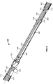
FIG. 2 is a perspective view of part of an example well screen system, omitting the cover sleeve and showing the exterior shrouds in cut-away for convenience of reference. -
FIGS. 3 is a perspective view of the part of the well screen system ofFIG. 2 , showing the cover sleeve and drain tube. -
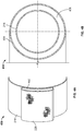
FIG. 4A is a perspective cross-sectional view of an example drain tube affixed to a cover sleeve, andFIG. 4B is an axial cross-sectional view of another example drain tube affixed to a cover sleeve. - Like reference symbols in the various drawings indicate like elements.
- In some implementations, in completing an open hole section of a well, a production string having one or more well screen assemblies is run into the open hole section of the well bore. The screen assemblies are axially spaced along the length of the string. Each screen assembly has a filtration screen that encircles a base pipe. The base pipe has portion with one or more apertures that allow communication of fluids through the screen, and a portion that is not apertured (i.e., fluid impermeable) outside of the screen. An apertured shroud is positioned around the exterior of the filtration screen. Shunt tubes run axially through the screen assembly from one end to the other, and are radially between the apertured shroud and base pipe. The ends of the filtration screen are capped with annular end rings. The screen assemblies thread end to end, and jumper tubes connect between the end rings to connect the shunt tubes of one screen assembly to the next. A cover sleeve is positioned around the jumper tubes between the screen assemblies. With the production string in place, the annulus around the well screen assemblies is "gravel packed." In gravel packing, a particulate (e.g., gravel) laden slurry is pumped into the wellbore exterior the string. The particulate is deposited in the annulus around the screen assemblies, and the carrier liquid in the slurry is drained into the center bore of the string through the well screen assemblies and pumped backed to the surface.
- Sometimes, especially when gravel packing a long well, variations in drainage of the carrier liquid from gravel slurry can cause inconsistencies, such as voids, to form in the gravel packing. The problem is particularly acute in solid, fluid impermeable portions of the string, for example at the ends of each screen assembly. A fluid permeable conduit, carried on the screen assemblies over the fluid impermeable portions (e.g., carried on the cover sleeve), can be implemented for communicating fluid from this region to the fluid permeable portions of the screen assemblies. The conduit allows the carrier liquid to more easily escape to the fluid permeable portions of the screen assemblies and be drained to the surface. The conduits may be in the form of drain tubes in locations where fluid draining is limited (e.g., fluid impermeable section, such as near ends of screen assemblies and/or elsewhere). The drain tubes can therefore reduce the possibility of voids and/or other inconsistences in the gravel pack.
-
FIG. 1 is a schematic side view of awell system 100 in accordance with the present disclosure. Thewell system 100 is shown as being a horizontal well, having awellbore 114 that extends substantially vertically from a wellhead 18 at the surface, then deviates to horizontal or substantially horizontal in the subterranean zone ofinterest 124. Acasing 116 is cemented in the vertical portion of the wellbore and coupled to thewellhead 118 at thesurface 120. The remainder of thewellbore 114 is completed open hole (i.e., without casing). Aproduction string 122 extends fromwellhead 118, through thewellbore 114 and into the subterranean zone ofinterest 124. - A production packer 126 seals the annulus between the
production string 122 and thecasing 116.Additional packers 126 can be provided between thescreen assemblies 112. Theproduction string 122 operates in producing fluids (e.g., oil, gas, and/or other fluids) from thesubterranean zone 124 to thesurface 120. Theproduction string 122 includes one or more well screen assemblies 112 (three shown). In some instances, the annulus between theproduction string 122 and the open hole portion of thewellbore 114 may be packed with gravel of a specified size. The well screen assemblies 112 and gravel packing allow communication of fluids between theproduction string 122 andsubterranean zone 124. The gravel packing provides a first stage of filtration against passage of particulate and larger fragments of the formation to theproduction string 122. The wellscreen assemblies 112 provide a second stage of filtration, and are configured to filter against passage of particulate of a specified size and larger into theproduction string 122. -
Portions 125 of the wellscreen assemblies 112 are fluid impermeable and cannot communicate fluid in thewellbore 114 to the center bore of thestring 122. One or more conduits,e.g. drain tubes 128, are carried on the outer diameter of thewell screen assemblies 112 to collect fluid in thewellbore 114, such as the carrier liquid from the gravel packing slurry, and communicate the fluid from fluid impermeable portions of thewell screen assemblies 112 orstring 122 through the gravel packing to fluid permeable portions of the wellscreen assemblies 112. In the context of gravel packing, as noted above, thedrain tubes 128 facilitate even draining of the carrier liquid from the gravel slurry; and therefore, more uniform gravel packing. - Although shown in the context of a
horizontal well system 100, the concepts herein can be applied to other well configurations, including vertical well systems consisting of a vertical or substantial vertical wellbore, multi-lateral well systems having multiple wellbores deviating from a common wellbore and/or other well systems. Also, although described in a production context, concepts herein can are applicable in other contexts, including injection (e.g., with thewell screen assembly 112 as part of an injection string), well treatment (e.g., with thewell screen assembly 112 as part of a treatment string) and/or other applications. -
FIG. 2 illustrates an example 200 of two well screen assemblies coupled together that can be used in the well system ofFIG. 1 . For convenience of description, the wellscreen system 200 is illustrated with its inner components exposed (i.e., theexterior shroud 201 is shown in partial break away). The wellscreen system 200 includes a firstwell screen assembly 202 and a secondwell screen assembly 203. The wellscreen assembly 202 includes abase pipe 205; and thewell screen assembly 203 includes abase pipe 207. Thebase pipes screen assembly 202 further includes a fluidpermeable screen 210 encircling thebase pipe 205. For example, thescreen 210 can include one or more layers of sheet mesh or wire wrapped screen (i.e., fluid permeable screen layers 214) with a selected industry rating for filtering particulate over a specified size. Similarly, thescreen assembly 203 further includes ascreen 215 encircling thebase pipe 207, thescreen 215 being similar to the screen 210 (with fluid permeable screen layers 212). Thescreen 210 is sealingly affixed to and spans between anend ring 232 and another end ring (not shown). Likewisescreen 215 is sealingly affixed to and spans between an end right 234 and another end ring (not shown). The end rings (includingend rings 232, 234) are sealingly affixed to thebase pipes screens base pipes screens base pipes permeable screens base pipes well screen assemblies screens base pipes screens base pipes - As illustrated in
FIG. 2 , eachwell screen assembly elongate shunt tube 224 is arranged axially along and spanning thescreen 210 and terminated atend ring 232. Theshunt tube 224 extends to another end ring (not shown) at the opposite end of thescreen 210, and may have an apertured or otherwise fluid permeable sidewall. Similarly, thewell screen assembly 203 includes anelongate shunt tube 226 that is arranged axially along and spanning thescreen 210 and terminated at anend ring 234, and may have an apertured or otherwise fluid permeable sidewall. Theshunt tube 226 may be substantially similar to theshunt tube 224. The shunt tubes are fluidically coupled byelongate jumper tubes 220 received between theshut tubes FIG. 3 , acover sleeve 218 can be provided over thejumper tubes 220 and the fluid impermeable portions of thebase pipes cover sleeve 218 can be apertured, in most instances it is solid and fluid impermeable. In certain instances, thecover sleeve 218 is not welded, adhered, held with fasteners or otherwise affixed to thewell screen assemblies -
FIG. 3 shows adrain tube 228 is adapted to collect fluid in the wellbore, e.g., the carrier fluid of the gravel packing slurry, from fluid impermeable portions of thewell screen assemblies well screen assemblies drain tube 228 includes a fluid permeable sidewall that allows fluid to enter an interior center passage of thedrain tube 228, flow to another location of thetube 228 and then flow out of the tube. Thus, for example, in the context of gravel packing, thetube 228 facilitates draining the carrier fluid from the gravel packing slurry in the region over thecover sleeve 218, because the carrier fluid can enter through the sidewall thedrain tube 228 at thecover sleeve 218 and be communicated uphole and/or downhole to the exterior of thescreens screens -
FIG. 3 andFIG. 4A show a configuration ofdrain tube 228 that runs beside thewell screen assemblies 202, 203 (i.e., thescreen assemblies drain tubes 228 could be provided arranged at different locations around the circumference of thewell screen assemblies FIG. 4B shows adrain tube 404 encircling thewell screen assemblies - In certain instances, the
drain tube cover sleeve 218.FIG. 3 shows thedrain tube 228 extending the entire length of thecover sleeve 218, spanning across the impermeable end portions of the base pipes, between the screens of thewell screen assemblies FIG. 4B ) can likewise extend the entire length of thecover sleeve 218. In certain instances, the drain tube 228 (FIG. 3 ) can traverse the end rings 232, 234 and have ends terminating radially over the screens (andapertured shrouds 201, 204) of thewell screen assemblies drain tube 228 can be open or closed. In an instance where thedrain tube 228 traverses an end ring and that end ring includes a centralizer, the centralizer can be configured to protect thedrain tube 228 during travel through the wellbore. If thedrain tube 228 does not traverse the end ring, gravel slurry access can be proved at the centralizer or in the centralizer. - The
drain tube 228 ofFIG. 4A has a non-circular cross-section, specifically a greater width (in the direction of the circumference of the cover sleeve 218) than thickness that facilitates maintain a smaller outer diameter of the entire assembly. Other cross-sections, including circular, rectangular, and non-symmetric cross-sections, could be used. In certain instances, thedrain tube 228 is a screen tube made of one or more layers of screen material, such as a welded or woven mesh, formed into a tube and partially flattened, retaining the internalcentral passage 402. Thedrain tube 404 ofFIG. 4B can also be made of a screen material formed in a tube and placed over thecover sleeve 218, retaining the internal central (annular)passage 406. The screen material results in sidewalls of thetube central passage drain tube - In use, as the string is made up at the surface, adjacent well screen assemblies are coupled end-to-end trapping the cover screen, with the drain tube affixed (welded, clamped, and/or otherwise) thereto, between them. The string is run into position in the wellbore, and gravel slurry introduced down the annulus between the string and the wellbore to fill the annuls with gravel. As the gravel is placed, the carrier liquid in the slurry is drained off through the well screen assemblies, into the center bore of the string and/or through the shunt tubes and withdrawn to the surface. Carrier fluid in regions around fluid impermeable portions of the well screen assemblies, such as near the cover sleeve and/or ends of the well screen assemblies, enters the fluid permeable sidewalls of the drain tubes and is transported up or downhole to the fluid permeable portions of the well screen assemblies. The drain tubes facilitate a more even drain of the gravel pack, and thus a more even distribution of gravel in the annulus with fewer voids.
- A number of embodiments have been described. Nevertheless, it will be understood that various modifications may be made. Accordingly, other embodiments are within the scope of the following claims.
Aspects of the invention are further described by the following numbered statements. - 1. A well screen system for use in a wellbore, comprising:
- an elongate base pipe;
- a screen encircling the base pipe and configured to filter against passage of particulate into a center bore of the base pipe, the base pipe having a fluid impermeable portion exterior to the screen;
- a cover sleeve over the fluid impermeable portion of the base pipe; and
- a drain tube comprising a fluid permeable sidewall residing exterior to the base pipe and screen, affixed to the cover sleeve, and adapted to communicate fluid from the wellbore around the fluid impermeable portion to the screen.
- 2. The well screen system of aspect 1, where the drain tube comprises a fluid permeable portion radially over the fluid impermeable portion of the base pipe and a fluid permeable portion radially over the screen.
- 3. The well screen system of aspect 1, where the drain tube comprises a screen material arranged as a flattened tube.
- 4. The well screen system of aspect 1, comprising an exterior shroud encircling the screen, and
where the drain tube encircles the shroud. - 5. The well screen system of aspect 4, where the drain tube encircles the cover sleeve.
- 6. The well screen system of aspect 5, comprising a shunt tube residing between the screen and the shroud.
- 7. The well screen system of aspect 1, where the drain tube resides along the side of the base pipe and the base pipe is outside of an interior center passage of the drain tube.
- 8. The well screen system of aspect 1, where the base pipe and the screen comprise a first base pipe and a first screen of a first well screen assembly; and
the well screen system further comprises a second well screen assembly coupled end-to-end with the first well screen assembly; and
where the drain tube spans between the first well screen assembly and the second well screen assembly and the fluid permeable sidewall of the drain tube resides radially over the fluid impermeable base pipe of the first well screen assembly and a fluid impermeable base pipe of the second well screen assembly. - 9. The well screen system of aspect 8, where an end of the drain tube resides radially over the exterior of the screen of the first well screen assembly and another end of the drain tube resides radially over the exterior of a screen of the second well screen assembly.
- 10. The well screen system of aspect 8, comprising:
- a first shunt tube axially spanning the screen and residing between the first screen and an exterior shroud of the first well screen assembly;
- a second shunt tube axially spanning a screen of the second well screen assembly and residing between the screen and an exterior shroud of the second well screen assembly;
- a jumper tube coupled to the first and second shunt tubes and residing radially over the fluid impermeable portions of the first and second base pipes; and
- an exterior cover sleeve over the jumper tube and the fluid impermeable portions of the first and second base pipes; and
- where the drain tube resides exterior to the cover sleeve.
- 11. The well screen system of
aspect 10, where the drain tube encircles the cover sleeve. - 12. The well screen system of
aspect 10, where the drain tube resides along the side of the exterior shrouds of the first well screen assembly and the second well screen assembly, and the well screen assemblies are outside of an internal center passage of the drain tube. - 13. A method, comprising:
- collecting a carrier fluid of a gravel packing slurry in a well bore annulus at a fluid impermeable portion of a well screen assembly in a tubing; and
- communicating the carrier fluid, via the tubing, through the gravel packing to a fluid permeable portion of the well screen assembly.
- 14. The method of aspect 13, comprising communicating the carrier fluid to a location radially over a fluid permeable screen of the well screen assembly.
- 15. The method of aspect 13, where the tubing comprises a fluid permeable screen and where collecting the carrier fluid comprises collecting the carrier fluid through the sidewall of the tubing and filtering against particulate of a specified size or larger.
- 16. The method of aspect 13, where communicating the carrier fluid, via the tubing, comprises communicating the fluid uphole towards the terranean surface.
Claims (4)
- A well system, comprising:a well screen assembly comprising a screen portion that is fluid permeable to a center bore of the assembly and a portion that is fluid impermeable to the center bore; anda conduit with fluid permeable sidewalls at the outer diameter of the well screen assembly and configured to communicate fluid from the fluid impermeable portion to the fluid permeable screen portion.
- The well system of claim 1, where the conduit comprises a screen tube.
- The well system of claim 1, where the conduit comprises a screen material encircling at least a portion of the fluid permeable screen portion and at least a portion of the fluid impermeable portion.
- The well system of claim 1, comprising:a second well screen assembly; andan exterior cover sleeve spanning the screen portion of the first well screen assembly to a screen portion of the second well screen assembly, andwhere the conduit comprises a screen tube residing outside the exterior cover sleeve, affixed to the cover sleeve and spanning between the screen portion of the first well screen assembly and the screen portion of the second well screen assembly.
Priority Applications (1)
| Application Number | Priority Date | Filing Date | Title |
|---|---|---|---|
| EP18171211.8A EP3388618B1 (en) | 2013-03-26 | 2013-03-26 | Exterior drain tube for well screen assemblies |
Applications Claiming Priority (3)
| Application Number | Priority Date | Filing Date | Title |
|---|---|---|---|
| PCT/US2013/033896 WO2014158141A1 (en) | 2013-03-26 | 2013-03-26 | Exterior drain tube for well screen assemblies |
| EP18171211.8A EP3388618B1 (en) | 2013-03-26 | 2013-03-26 | Exterior drain tube for well screen assemblies |
| EP13880279.8A EP2978930B1 (en) | 2013-03-26 | 2013-03-26 | Exterior drain tube for well screen assemblies |
Related Parent Applications (1)
| Application Number | Title | Priority Date | Filing Date |
|---|---|---|---|
| EP13880279.8A Division EP2978930B1 (en) | 2013-03-26 | 2013-03-26 | Exterior drain tube for well screen assemblies |
Publications (2)
| Publication Number | Publication Date |
|---|---|
| EP3388618A1 true EP3388618A1 (en) | 2018-10-17 |
| EP3388618B1 EP3388618B1 (en) | 2020-10-21 |
Family
ID=51624927
Family Applications (2)
| Application Number | Title | Priority Date | Filing Date |
|---|---|---|---|
| EP18171211.8A Active EP3388618B1 (en) | 2013-03-26 | 2013-03-26 | Exterior drain tube for well screen assemblies |
| EP13880279.8A Active EP2978930B1 (en) | 2013-03-26 | 2013-03-26 | Exterior drain tube for well screen assemblies |
Family Applications After (1)
| Application Number | Title | Priority Date | Filing Date |
|---|---|---|---|
| EP13880279.8A Active EP2978930B1 (en) | 2013-03-26 | 2013-03-26 | Exterior drain tube for well screen assemblies |
Country Status (5)
| Country | Link |
|---|---|
| US (1) | US9725988B2 (en) |
| EP (2) | EP3388618B1 (en) |
| AU (1) | AU2013384294B2 (en) |
| SG (1) | SG11201506416SA (en) |
| WO (1) | WO2014158141A1 (en) |
Families Citing this family (6)
| Publication number | Priority date | Publication date | Assignee | Title |
|---|---|---|---|---|
| AU2016296605B2 (en) * | 2015-07-22 | 2019-03-14 | Weatherford Technology Holdings, LLC. | Leak-off assembly for gravel pack system |
| GB2553823B (en) | 2016-09-15 | 2021-01-20 | Weatherford Uk Ltd | Apparatus and methods for use in wellbore packing |
| RU2720207C1 (en) * | 2018-06-22 | 2020-04-28 | Халлибертон Энерджи Сервисез, Инк. | Multiple shunt pressure unit for gravel packing |
| WO2020172092A1 (en) | 2019-02-20 | 2020-08-27 | Schlumberger Technology Corporation | Non-metallic compliant sand control screen |
| WO2022047281A1 (en) * | 2020-08-31 | 2022-03-03 | Schlumberger Technology Corporation | Gravel packing with base pipe having limited open flow area |
| WO2022081440A1 (en) | 2020-10-13 | 2022-04-21 | Schlumberger Technology Corporation | Elastomer alloy for intelligent sand management |
Citations (9)
| Publication number | Priority date | Publication date | Assignee | Title |
|---|---|---|---|---|
| US5890533A (en) * | 1997-07-29 | 1999-04-06 | Mobil Oil Corporation | Alternate path well tool having an internal shunt tube |
| US20020038707A1 (en) * | 2000-09-29 | 2002-04-04 | United States Filter Corporation | Well screen |
| US20020079099A1 (en) * | 2000-12-22 | 2002-06-27 | Hurst Gary D. | Apparatus and method providing alternate fluid flowpath for gravel pack completion |
| US6644406B1 (en) * | 2000-07-31 | 2003-11-11 | Mobil Oil Corporation | Fracturing different levels within a completion interval of a well |
| US20080066900A1 (en) * | 2006-09-19 | 2008-03-20 | Schlumberger Technology Corporation | Gravel pack apparatus that includes a swellable element |
| US20100059232A1 (en) * | 2008-09-05 | 2010-03-11 | Schlumberger Technology Corporation | System and method for retaining an element |
| US20100236779A1 (en) * | 2008-11-11 | 2010-09-23 | Swelltec Limited | Apparatus and Method for Use with Alternate Path Sand Control Completions |
| US20110011586A1 (en) * | 2008-08-29 | 2011-01-20 | Halliburton Energy Services, Inc. | Sand control screen assembly and method for use of same |
| US20110297376A1 (en) * | 2010-06-08 | 2011-12-08 | Halliburton Energy Services, Inc. | Sand Control Screen Assembly Having Control Line Capture Capability |
Family Cites Families (12)
| Publication number | Priority date | Publication date | Assignee | Title |
|---|---|---|---|---|
| US2323992A (en) * | 1941-05-07 | 1943-07-13 | Hardeman Lyman Lynch | Well shaft |
| US5588487A (en) * | 1995-09-12 | 1996-12-31 | Mobil Oil Corporation | Tool for blocking axial flow in gravel-packed well annulus |
| US5868200A (en) * | 1997-04-17 | 1999-02-09 | Mobil Oil Corporation | Alternate-path well screen having protected shunt connection |
| US6848510B2 (en) * | 2001-01-16 | 2005-02-01 | Schlumberger Technology Corporation | Screen and method having a partial screen wrap |
| US6752207B2 (en) | 2001-08-07 | 2004-06-22 | Schlumberger Technology Corporation | Apparatus and method for alternate path system |
| US7048061B2 (en) | 2003-02-21 | 2006-05-23 | Weatherford/Lamb, Inc. | Screen assembly with flow through connectors |
| US7497267B2 (en) | 2005-06-16 | 2009-03-03 | Weatherford/Lamb, Inc. | Shunt tube connector lock |
| US7984760B2 (en) * | 2006-04-03 | 2011-07-26 | Exxonmobil Upstream Research Company | Wellbore method and apparatus for sand and inflow control during well operations |
| US7828056B2 (en) | 2007-07-06 | 2010-11-09 | Schlumberger Technology Corporation | Method and apparatus for connecting shunt tubes to sand screen assemblies |
| US7789152B2 (en) * | 2008-05-13 | 2010-09-07 | Baker Hughes Incorporated | Plug protection system and method |
| US8550157B2 (en) * | 2009-07-15 | 2013-10-08 | Baker Hughes Incorporated | Apparatus and method for controlling flow of solids into wellbores using filter media containing an array of three dimensional elements |
| US9085960B2 (en) | 2010-10-28 | 2015-07-21 | Weatherford Technology Holdings, Llc | Gravel pack bypass assembly |
-
2013
- 2013-03-26 WO PCT/US2013/033896 patent/WO2014158141A1/en not_active Ceased
- 2013-03-26 EP EP18171211.8A patent/EP3388618B1/en active Active
- 2013-03-26 AU AU2013384294A patent/AU2013384294B2/en active Active
- 2013-03-26 SG SG11201506416SA patent/SG11201506416SA/en unknown
- 2013-03-26 EP EP13880279.8A patent/EP2978930B1/en active Active
- 2013-03-26 US US14/346,891 patent/US9725988B2/en active Active
Patent Citations (9)
| Publication number | Priority date | Publication date | Assignee | Title |
|---|---|---|---|---|
| US5890533A (en) * | 1997-07-29 | 1999-04-06 | Mobil Oil Corporation | Alternate path well tool having an internal shunt tube |
| US6644406B1 (en) * | 2000-07-31 | 2003-11-11 | Mobil Oil Corporation | Fracturing different levels within a completion interval of a well |
| US20020038707A1 (en) * | 2000-09-29 | 2002-04-04 | United States Filter Corporation | Well screen |
| US20020079099A1 (en) * | 2000-12-22 | 2002-06-27 | Hurst Gary D. | Apparatus and method providing alternate fluid flowpath for gravel pack completion |
| US20080066900A1 (en) * | 2006-09-19 | 2008-03-20 | Schlumberger Technology Corporation | Gravel pack apparatus that includes a swellable element |
| US20110011586A1 (en) * | 2008-08-29 | 2011-01-20 | Halliburton Energy Services, Inc. | Sand control screen assembly and method for use of same |
| US20100059232A1 (en) * | 2008-09-05 | 2010-03-11 | Schlumberger Technology Corporation | System and method for retaining an element |
| US20100236779A1 (en) * | 2008-11-11 | 2010-09-23 | Swelltec Limited | Apparatus and Method for Use with Alternate Path Sand Control Completions |
| US20110297376A1 (en) * | 2010-06-08 | 2011-12-08 | Halliburton Energy Services, Inc. | Sand Control Screen Assembly Having Control Line Capture Capability |
Also Published As
| Publication number | Publication date |
|---|---|
| EP2978930B1 (en) | 2018-05-09 |
| EP2978930A4 (en) | 2017-04-05 |
| EP3388618B1 (en) | 2020-10-21 |
| AU2013384294B2 (en) | 2016-06-02 |
| US20160003014A1 (en) | 2016-01-07 |
| WO2014158141A1 (en) | 2014-10-02 |
| SG11201506416SA (en) | 2015-09-29 |
| US9725988B2 (en) | 2017-08-08 |
| AU2013384294A1 (en) | 2015-09-17 |
| EP2978930A1 (en) | 2016-02-03 |
Similar Documents
| Publication | Publication Date | Title |
|---|---|---|
| CA2360472C (en) | Sand screen with communication line conduit | |
| US8567498B2 (en) | System and method for filtering sand in a wellbore | |
| US8291971B2 (en) | Crimped end wrapped on pipe well screen | |
| AU2010234433B2 (en) | Well screen assembly with multi-gage wire wrapped layer | |
| EP2978930B1 (en) | Exterior drain tube for well screen assemblies | |
| US20100258302A1 (en) | Well Screen With Drainage Assembly | |
| US10400554B2 (en) | Longitudinally offset partial areas screens for well assembly | |
| NO20191342A1 (en) | Material mesh for screening fines | |
| US9752417B2 (en) | Gravel packing apparatus having optimized fluid handling | |
| US20140014357A1 (en) | System and method for sand and inflow control | |
| AU2013405210B2 (en) | Gravel packing apparatus having optimized fluid handling |
Legal Events
| Date | Code | Title | Description |
|---|---|---|---|
| PUAI | Public reference made under article 153(3) epc to a published international application that has entered the european phase |
Free format text: ORIGINAL CODE: 0009012 |
|
| STAA | Information on the status of an ep patent application or granted ep patent |
Free format text: STATUS: THE APPLICATION HAS BEEN PUBLISHED |
|
| AC | Divisional application: reference to earlier application |
Ref document number: 2978930 Country of ref document: EP Kind code of ref document: P |
|
| AK | Designated contracting states |
Kind code of ref document: A1 Designated state(s): AL AT BE BG CH CY CZ DE DK EE ES FI FR GB GR HR HU IE IS IT LI LT LU LV MC MK MT NL NO PL PT RO RS SE SI SK SM TR |
|
| STAA | Information on the status of an ep patent application or granted ep patent |
Free format text: STATUS: REQUEST FOR EXAMINATION WAS MADE |
|
| 17P | Request for examination filed |
Effective date: 20190415 |
|
| RBV | Designated contracting states (corrected) |
Designated state(s): AL AT BE BG CH CY CZ DE DK EE ES FI FR GB GR HR HU IE IS IT LI LT LU LV MC MK MT NL NO PL PT RO RS SE SI SK SM TR |
|
| RAP1 | Party data changed (applicant data changed or rights of an application transferred) |
Owner name: HALLIBURTON ENERGY SERVICES INC. |
|
| STAA | Information on the status of an ep patent application or granted ep patent |
Free format text: STATUS: EXAMINATION IS IN PROGRESS |
|
| 17Q | First examination report despatched |
Effective date: 20191018 |
|
| GRAP | Despatch of communication of intention to grant a patent |
Free format text: ORIGINAL CODE: EPIDOSNIGR1 |
|
| STAA | Information on the status of an ep patent application or granted ep patent |
Free format text: STATUS: GRANT OF PATENT IS INTENDED |
|
| INTG | Intention to grant announced |
Effective date: 20200512 |
|
| GRAS | Grant fee paid |
Free format text: ORIGINAL CODE: EPIDOSNIGR3 |
|
| GRAA | (expected) grant |
Free format text: ORIGINAL CODE: 0009210 |
|
| STAA | Information on the status of an ep patent application or granted ep patent |
Free format text: STATUS: THE PATENT HAS BEEN GRANTED |
|
| AC | Divisional application: reference to earlier application |
Ref document number: 2978930 Country of ref document: EP Kind code of ref document: P |
|
| AK | Designated contracting states |
Kind code of ref document: B1 Designated state(s): AL AT BE BG CH CY CZ DE DK EE ES FI FR GB GR HR HU IE IS IT LI LT LU LV MC MK MT NL NO PL PT RO RS SE SI SK SM TR |
|
| REG | Reference to a national code |
Ref country code: GB Ref legal event code: FG4D |
|
| REG | Reference to a national code |
Ref country code: CH Ref legal event code: EP |
|
| REG | Reference to a national code |
Ref country code: IE Ref legal event code: FG4D |
|
| REG | Reference to a national code |
Ref country code: DE Ref legal event code: R096 Ref document number: 602013073550 Country of ref document: DE |
|
| REG | Reference to a national code |
Ref country code: AT Ref legal event code: REF Ref document number: 1326031 Country of ref document: AT Kind code of ref document: T Effective date: 20201115 |
|
| REG | Reference to a national code |
Ref country code: NO Ref legal event code: T2 Effective date: 20201021 |
|
| REG | Reference to a national code |
Ref country code: AT Ref legal event code: MK05 Ref document number: 1326031 Country of ref document: AT Kind code of ref document: T Effective date: 20201021 |
|
| REG | Reference to a national code |
Ref country code: NL Ref legal event code: MP Effective date: 20201021 |
|
| PG25 | Lapsed in a contracting state [announced via postgrant information from national office to epo] |
Ref country code: FI Free format text: LAPSE BECAUSE OF FAILURE TO SUBMIT A TRANSLATION OF THE DESCRIPTION OR TO PAY THE FEE WITHIN THE PRESCRIBED TIME-LIMIT Effective date: 20201021 Ref country code: PT Free format text: LAPSE BECAUSE OF FAILURE TO SUBMIT A TRANSLATION OF THE DESCRIPTION OR TO PAY THE FEE WITHIN THE PRESCRIBED TIME-LIMIT Effective date: 20210222 Ref country code: RS Free format text: LAPSE BECAUSE OF FAILURE TO SUBMIT A TRANSLATION OF THE DESCRIPTION OR TO PAY THE FEE WITHIN THE PRESCRIBED TIME-LIMIT Effective date: 20201021 Ref country code: GR Free format text: LAPSE BECAUSE OF FAILURE TO SUBMIT A TRANSLATION OF THE DESCRIPTION OR TO PAY THE FEE WITHIN THE PRESCRIBED TIME-LIMIT Effective date: 20210122 |
|
| REG | Reference to a national code |
Ref country code: LT Ref legal event code: MG4D |
|
| PG25 | Lapsed in a contracting state [announced via postgrant information from national office to epo] |
Ref country code: BG Free format text: LAPSE BECAUSE OF FAILURE TO SUBMIT A TRANSLATION OF THE DESCRIPTION OR TO PAY THE FEE WITHIN THE PRESCRIBED TIME-LIMIT Effective date: 20210121 Ref country code: PL Free format text: LAPSE BECAUSE OF FAILURE TO SUBMIT A TRANSLATION OF THE DESCRIPTION OR TO PAY THE FEE WITHIN THE PRESCRIBED TIME-LIMIT Effective date: 20201021 Ref country code: IS Free format text: LAPSE BECAUSE OF FAILURE TO SUBMIT A TRANSLATION OF THE DESCRIPTION OR TO PAY THE FEE WITHIN THE PRESCRIBED TIME-LIMIT Effective date: 20210221 Ref country code: LV Free format text: LAPSE BECAUSE OF FAILURE TO SUBMIT A TRANSLATION OF THE DESCRIPTION OR TO PAY THE FEE WITHIN THE PRESCRIBED TIME-LIMIT Effective date: 20201021 Ref country code: SE Free format text: LAPSE BECAUSE OF FAILURE TO SUBMIT A TRANSLATION OF THE DESCRIPTION OR TO PAY THE FEE WITHIN THE PRESCRIBED TIME-LIMIT Effective date: 20201021 Ref country code: ES Free format text: LAPSE BECAUSE OF FAILURE TO SUBMIT A TRANSLATION OF THE DESCRIPTION OR TO PAY THE FEE WITHIN THE PRESCRIBED TIME-LIMIT Effective date: 20201021 Ref country code: AT Free format text: LAPSE BECAUSE OF FAILURE TO SUBMIT A TRANSLATION OF THE DESCRIPTION OR TO PAY THE FEE WITHIN THE PRESCRIBED TIME-LIMIT Effective date: 20201021 |
|
| PG25 | Lapsed in a contracting state [announced via postgrant information from national office to epo] |
Ref country code: HR Free format text: LAPSE BECAUSE OF FAILURE TO SUBMIT A TRANSLATION OF THE DESCRIPTION OR TO PAY THE FEE WITHIN THE PRESCRIBED TIME-LIMIT Effective date: 20201021 Ref country code: NL Free format text: LAPSE BECAUSE OF FAILURE TO SUBMIT A TRANSLATION OF THE DESCRIPTION OR TO PAY THE FEE WITHIN THE PRESCRIBED TIME-LIMIT Effective date: 20201021 |
|
| REG | Reference to a national code |
Ref country code: DE Ref legal event code: R097 Ref document number: 602013073550 Country of ref document: DE |
|
| PG25 | Lapsed in a contracting state [announced via postgrant information from national office to epo] |
Ref country code: LT Free format text: LAPSE BECAUSE OF FAILURE TO SUBMIT A TRANSLATION OF THE DESCRIPTION OR TO PAY THE FEE WITHIN THE PRESCRIBED TIME-LIMIT Effective date: 20201021 Ref country code: RO Free format text: LAPSE BECAUSE OF FAILURE TO SUBMIT A TRANSLATION OF THE DESCRIPTION OR TO PAY THE FEE WITHIN THE PRESCRIBED TIME-LIMIT Effective date: 20201021 Ref country code: SK Free format text: LAPSE BECAUSE OF FAILURE TO SUBMIT A TRANSLATION OF THE DESCRIPTION OR TO PAY THE FEE WITHIN THE PRESCRIBED TIME-LIMIT Effective date: 20201021 Ref country code: SM Free format text: LAPSE BECAUSE OF FAILURE TO SUBMIT A TRANSLATION OF THE DESCRIPTION OR TO PAY THE FEE WITHIN THE PRESCRIBED TIME-LIMIT Effective date: 20201021 Ref country code: CZ Free format text: LAPSE BECAUSE OF FAILURE TO SUBMIT A TRANSLATION OF THE DESCRIPTION OR TO PAY THE FEE WITHIN THE PRESCRIBED TIME-LIMIT Effective date: 20201021 Ref country code: EE Free format text: LAPSE BECAUSE OF FAILURE TO SUBMIT A TRANSLATION OF THE DESCRIPTION OR TO PAY THE FEE WITHIN THE PRESCRIBED TIME-LIMIT Effective date: 20201021 |
|
| PLBE | No opposition filed within time limit |
Free format text: ORIGINAL CODE: 0009261 |
|
| STAA | Information on the status of an ep patent application or granted ep patent |
Free format text: STATUS: NO OPPOSITION FILED WITHIN TIME LIMIT |
|
| PG25 | Lapsed in a contracting state [announced via postgrant information from national office to epo] |
Ref country code: DK Free format text: LAPSE BECAUSE OF FAILURE TO SUBMIT A TRANSLATION OF THE DESCRIPTION OR TO PAY THE FEE WITHIN THE PRESCRIBED TIME-LIMIT Effective date: 20201021 |
|
| 26N | No opposition filed |
Effective date: 20210722 |
|
| REG | Reference to a national code |
Ref country code: DE Ref legal event code: R119 Ref document number: 602013073550 Country of ref document: DE |
|
| PG25 | Lapsed in a contracting state [announced via postgrant information from national office to epo] |
Ref country code: AL Free format text: LAPSE BECAUSE OF FAILURE TO SUBMIT A TRANSLATION OF THE DESCRIPTION OR TO PAY THE FEE WITHIN THE PRESCRIBED TIME-LIMIT Effective date: 20201021 Ref country code: IT Free format text: LAPSE BECAUSE OF FAILURE TO SUBMIT A TRANSLATION OF THE DESCRIPTION OR TO PAY THE FEE WITHIN THE PRESCRIBED TIME-LIMIT Effective date: 20201021 Ref country code: MC Free format text: LAPSE BECAUSE OF FAILURE TO SUBMIT A TRANSLATION OF THE DESCRIPTION OR TO PAY THE FEE WITHIN THE PRESCRIBED TIME-LIMIT Effective date: 20201021 |
|
| REG | Reference to a national code |
Ref country code: CH Ref legal event code: PL |
|
| PG25 | Lapsed in a contracting state [announced via postgrant information from national office to epo] |
Ref country code: SI Free format text: LAPSE BECAUSE OF FAILURE TO SUBMIT A TRANSLATION OF THE DESCRIPTION OR TO PAY THE FEE WITHIN THE PRESCRIBED TIME-LIMIT Effective date: 20201021 |
|
| REG | Reference to a national code |
Ref country code: BE Ref legal event code: MM Effective date: 20210331 |
|
| PG25 | Lapsed in a contracting state [announced via postgrant information from national office to epo] |
Ref country code: CH Free format text: LAPSE BECAUSE OF NON-PAYMENT OF DUE FEES Effective date: 20210331 Ref country code: DE Free format text: LAPSE BECAUSE OF NON-PAYMENT OF DUE FEES Effective date: 20211001 Ref country code: IE Free format text: LAPSE BECAUSE OF NON-PAYMENT OF DUE FEES Effective date: 20210326 Ref country code: LI Free format text: LAPSE BECAUSE OF NON-PAYMENT OF DUE FEES Effective date: 20210331 Ref country code: LU Free format text: LAPSE BECAUSE OF NON-PAYMENT OF DUE FEES Effective date: 20210326 |
|
| PG25 | Lapsed in a contracting state [announced via postgrant information from national office to epo] |
Ref country code: IS Free format text: LAPSE BECAUSE OF FAILURE TO SUBMIT A TRANSLATION OF THE DESCRIPTION OR TO PAY THE FEE WITHIN THE PRESCRIBED TIME-LIMIT Effective date: 20210221 |
|
| PG25 | Lapsed in a contracting state [announced via postgrant information from national office to epo] |
Ref country code: BE Free format text: LAPSE BECAUSE OF NON-PAYMENT OF DUE FEES Effective date: 20210331 |
|
| PG25 | Lapsed in a contracting state [announced via postgrant information from national office to epo] |
Ref country code: CY Free format text: LAPSE BECAUSE OF FAILURE TO SUBMIT A TRANSLATION OF THE DESCRIPTION OR TO PAY THE FEE WITHIN THE PRESCRIBED TIME-LIMIT Effective date: 20201021 |
|
| PG25 | Lapsed in a contracting state [announced via postgrant information from national office to epo] |
Ref country code: HU Free format text: LAPSE BECAUSE OF FAILURE TO SUBMIT A TRANSLATION OF THE DESCRIPTION OR TO PAY THE FEE WITHIN THE PRESCRIBED TIME-LIMIT; INVALID AB INITIO Effective date: 20130326 |
|
| PG25 | Lapsed in a contracting state [announced via postgrant information from national office to epo] |
Ref country code: MK Free format text: LAPSE BECAUSE OF FAILURE TO SUBMIT A TRANSLATION OF THE DESCRIPTION OR TO PAY THE FEE WITHIN THE PRESCRIBED TIME-LIMIT Effective date: 20201021 |
|
| PG25 | Lapsed in a contracting state [announced via postgrant information from national office to epo] |
Ref country code: MT Free format text: LAPSE BECAUSE OF FAILURE TO SUBMIT A TRANSLATION OF THE DESCRIPTION OR TO PAY THE FEE WITHIN THE PRESCRIBED TIME-LIMIT Effective date: 20201021 |
|
| PG25 | Lapsed in a contracting state [announced via postgrant information from national office to epo] |
Ref country code: TR Free format text: LAPSE BECAUSE OF FAILURE TO SUBMIT A TRANSLATION OF THE DESCRIPTION OR TO PAY THE FEE WITHIN THE PRESCRIBED TIME-LIMIT Effective date: 20201021 |
|
| PGFP | Annual fee paid to national office [announced via postgrant information from national office to epo] |
Ref country code: GB Payment date: 20260202 Year of fee payment: 14 |
|
| PGFP | Annual fee paid to national office [announced via postgrant information from national office to epo] |
Ref country code: NO Payment date: 20260223 Year of fee payment: 14 |
|
| PGFP | Annual fee paid to national office [announced via postgrant information from national office to epo] |
Ref country code: FR Payment date: 20260220 Year of fee payment: 14 |