EP3388340B1 - Meal/beverage trolley convertible to waste trolley - Google Patents
Meal/beverage trolley convertible to waste trolley Download PDFInfo
- Publication number
- EP3388340B1 EP3388340B1 EP18167199.1A EP18167199A EP3388340B1 EP 3388340 B1 EP3388340 B1 EP 3388340B1 EP 18167199 A EP18167199 A EP 18167199A EP 3388340 B1 EP3388340 B1 EP 3388340B1
- Authority
- EP
- European Patent Office
- Prior art keywords
- trolley
- waste
- dry ice
- ice compartment
- sliding
- Prior art date
- Legal status (The legal status is an assumption and is not a legal conclusion. Google has not performed a legal analysis and makes no representation as to the accuracy of the status listed.)
- Not-in-force
Links
Images







Classifications
-
- A—HUMAN NECESSITIES
- A47—FURNITURE; DOMESTIC ARTICLES OR APPLIANCES; COFFEE MILLS; SPICE MILLS; SUCTION CLEANERS IN GENERAL
- A47B—TABLES; DESKS; OFFICE FURNITURE; CABINETS; DRAWERS; GENERAL DETAILS OF FURNITURE
- A47B31/00—Service or tea tables, trolleys, or wagons
- A47B31/001—Service or tea tables, trolleys, or wagons with devices for laying, clearing, cleaning, or the like, a table
-
- B—PERFORMING OPERATIONS; TRANSPORTING
- B64—AIRCRAFT; AVIATION; COSMONAUTICS
- B64D—EQUIPMENT FOR FITTING IN OR TO AIRCRAFT; FLIGHT SUITS; PARACHUTES; ARRANGEMENT OR MOUNTING OF POWER PLANTS OR PROPULSION TRANSMISSIONS IN AIRCRAFT
- B64D11/00—Passenger or crew accommodation; Flight-deck installations not otherwise provided for
- B64D11/0007—Devices specially adapted for food or beverage distribution services
-
- A—HUMAN NECESSITIES
- A47—FURNITURE; DOMESTIC ARTICLES OR APPLIANCES; COFFEE MILLS; SPICE MILLS; SUCTION CLEANERS IN GENERAL
- A47B—TABLES; DESKS; OFFICE FURNITURE; CABINETS; DRAWERS; GENERAL DETAILS OF FURNITURE
- A47B31/00—Service or tea tables, trolleys, or wagons
- A47B31/02—Service or tea tables, trolleys, or wagons with heating, cooling or ventilating means
-
- B—PERFORMING OPERATIONS; TRANSPORTING
- B62—LAND VEHICLES FOR TRAVELLING OTHERWISE THAN ON RAILS
- B62B—HAND-PROPELLED VEHICLES, e.g. HAND CARTS OR PERAMBULATORS; SLEDGES
- B62B3/00—Hand carts having more than one axis carrying transport wheels; Steering devices therefor; Equipment therefor
- B62B3/02—Hand carts having more than one axis carrying transport wheels; Steering devices therefor; Equipment therefor involving parts being adjustable, collapsible, attachable, detachable or convertible
-
- B—PERFORMING OPERATIONS; TRANSPORTING
- B64—AIRCRAFT; AVIATION; COSMONAUTICS
- B64D—EQUIPMENT FOR FITTING IN OR TO AIRCRAFT; FLIGHT SUITS; PARACHUTES; ARRANGEMENT OR MOUNTING OF POWER PLANTS OR PROPULSION TRANSMISSIONS IN AIRCRAFT
- B64D11/00—Passenger or crew accommodation; Flight-deck installations not otherwise provided for
- B64D11/04—Galleys
-
- B—PERFORMING OPERATIONS; TRANSPORTING
- B65—CONVEYING; PACKING; STORING; HANDLING THIN OR FILAMENTARY MATERIAL
- B65F—GATHERING OR REMOVAL OF DOMESTIC OR LIKE REFUSE
- B65F1/00—Refuse receptacles; Accessories therefor
- B65F1/14—Other constructional features; Accessories
- B65F1/141—Supports, racks, stands, posts or the like for holding refuse receptacles
- B65F1/1415—Supports, racks, stands, posts or the like for holding refuse receptacles for flexible receptables, e.g. bags, sacks
-
- B—PERFORMING OPERATIONS; TRANSPORTING
- B65—CONVEYING; PACKING; STORING; HANDLING THIN OR FILAMENTARY MATERIAL
- B65F—GATHERING OR REMOVAL OF DOMESTIC OR LIKE REFUSE
- B65F1/00—Refuse receptacles; Accessories therefor
- B65F1/14—Other constructional features; Accessories
- B65F1/1468—Means for facilitating the transport of the receptacle, e.g. wheels, rolls
- B65F1/1473—Receptacles having wheels
-
- B—PERFORMING OPERATIONS; TRANSPORTING
- B65—CONVEYING; PACKING; STORING; HANDLING THIN OR FILAMENTARY MATERIAL
- B65F—GATHERING OR REMOVAL OF DOMESTIC OR LIKE REFUSE
- B65F3/00—Vehicles particularly adapted for collecting refuse
- B65F3/005—Hand-operated refuse vehicles
-
- F—MECHANICAL ENGINEERING; LIGHTING; HEATING; WEAPONS; BLASTING
- F25—REFRIGERATION OR COOLING; COMBINED HEATING AND REFRIGERATION SYSTEMS; HEAT PUMP SYSTEMS; MANUFACTURE OR STORAGE OF ICE; LIQUEFACTION SOLIDIFICATION OF GASES
- F25D—REFRIGERATORS; COLD ROOMS; ICE-BOXES; COOLING OR FREEZING APPARATUS NOT OTHERWISE PROVIDED FOR
- F25D3/00—Devices using other cold materials; Devices using cold-storage bodies
- F25D3/12—Devices using other cold materials; Devices using cold-storage bodies using solidified gases, e.g. carbon-dioxide snow
- F25D3/125—Movable containers
-
- A—HUMAN NECESSITIES
- A47—FURNITURE; DOMESTIC ARTICLES OR APPLIANCES; COFFEE MILLS; SPICE MILLS; SUCTION CLEANERS IN GENERAL
- A47B—TABLES; DESKS; OFFICE FURNITURE; CABINETS; DRAWERS; GENERAL DETAILS OF FURNITURE
- A47B31/00—Service or tea tables, trolleys, or wagons
- A47B2031/002—Catering trolleys
-
- A—HUMAN NECESSITIES
- A47—FURNITURE; DOMESTIC ARTICLES OR APPLIANCES; COFFEE MILLS; SPICE MILLS; SUCTION CLEANERS IN GENERAL
- A47B—TABLES; DESKS; OFFICE FURNITURE; CABINETS; DRAWERS; GENERAL DETAILS OF FURNITURE
- A47B31/00—Service or tea tables, trolleys, or wagons
- A47B2031/003—Service or tea tables, trolleys, or wagons with drawers, trays or shelves
-
- A—HUMAN NECESSITIES
- A47—FURNITURE; DOMESTIC ARTICLES OR APPLIANCES; COFFEE MILLS; SPICE MILLS; SUCTION CLEANERS IN GENERAL
- A47B—TABLES; DESKS; OFFICE FURNITURE; CABINETS; DRAWERS; GENERAL DETAILS OF FURNITURE
- A47B31/00—Service or tea tables, trolleys, or wagons
- A47B31/02—Service or tea tables, trolleys, or wagons with heating, cooling or ventilating means
- A47B2031/023—Service or tea tables, trolleys, or wagons with heating, cooling or ventilating means being dockable to a stationary refrigeration and heating unit
-
- B—PERFORMING OPERATIONS; TRANSPORTING
- B62—LAND VEHICLES FOR TRAVELLING OTHERWISE THAN ON RAILS
- B62B—HAND-PROPELLED VEHICLES, e.g. HAND CARTS OR PERAMBULATORS; SLEDGES
- B62B2202/00—Indexing codes relating to type or characteristics of transported articles
- B62B2202/02—Cylindrically-shaped articles, e.g. drums, barrels, flasks
- B62B2202/021—Bottles
-
- B—PERFORMING OPERATIONS; TRANSPORTING
- B62—LAND VEHICLES FOR TRAVELLING OTHERWISE THAN ON RAILS
- B62B—HAND-PROPELLED VEHICLES, e.g. HAND CARTS OR PERAMBULATORS; SLEDGES
- B62B2202/00—Indexing codes relating to type or characteristics of transported articles
- B62B2202/20—Dustbins, refuse containers
-
- B—PERFORMING OPERATIONS; TRANSPORTING
- B62—LAND VEHICLES FOR TRAVELLING OTHERWISE THAN ON RAILS
- B62B—HAND-PROPELLED VEHICLES, e.g. HAND CARTS OR PERAMBULATORS; SLEDGES
- B62B2202/00—Indexing codes relating to type or characteristics of transported articles
- B62B2202/67—Service trolleys, e.g. in aircraft
-
- B—PERFORMING OPERATIONS; TRANSPORTING
- B62—LAND VEHICLES FOR TRAVELLING OTHERWISE THAN ON RAILS
- B62B—HAND-PROPELLED VEHICLES, e.g. HAND CARTS OR PERAMBULATORS; SLEDGES
- B62B2204/00—Ventilation; Heating; Cooling; Insulation
- B62B2204/04—Ventilation; Heating; Cooling; Insulation comprising a cooling unit
-
- B—PERFORMING OPERATIONS; TRANSPORTING
- B62—LAND VEHICLES FOR TRAVELLING OTHERWISE THAN ON RAILS
- B62B—HAND-PROPELLED VEHICLES, e.g. HAND CARTS OR PERAMBULATORS; SLEDGES
- B62B2206/00—Adjustable or convertible hand-propelled vehicles or sledges
- B62B2206/006—Convertible hand-propelled vehicles or sledges
-
- B—PERFORMING OPERATIONS; TRANSPORTING
- B62—LAND VEHICLES FOR TRAVELLING OTHERWISE THAN ON RAILS
- B62B—HAND-PROPELLED VEHICLES, e.g. HAND CARTS OR PERAMBULATORS; SLEDGES
- B62B3/00—Hand carts having more than one axis carrying transport wheels; Steering devices therefor; Equipment therefor
- B62B3/002—Hand carts having more than one axis carrying transport wheels; Steering devices therefor; Equipment therefor characterised by a rectangular shape, involving sidewalls or racks
- B62B3/003—Non-transparent side walls
-
- B—PERFORMING OPERATIONS; TRANSPORTING
- B62—LAND VEHICLES FOR TRAVELLING OTHERWISE THAN ON RAILS
- B62B—HAND-PROPELLED VEHICLES, e.g. HAND CARTS OR PERAMBULATORS; SLEDGES
- B62B3/00—Hand carts having more than one axis carrying transport wheels; Steering devices therefor; Equipment therefor
- B62B3/002—Hand carts having more than one axis carrying transport wheels; Steering devices therefor; Equipment therefor characterised by a rectangular shape, involving sidewalls or racks
- B62B3/004—Details of doors or cover lids
-
- B—PERFORMING OPERATIONS; TRANSPORTING
- B62—LAND VEHICLES FOR TRAVELLING OTHERWISE THAN ON RAILS
- B62B—HAND-PROPELLED VEHICLES, e.g. HAND CARTS OR PERAMBULATORS; SLEDGES
- B62B3/00—Hand carts having more than one axis carrying transport wheels; Steering devices therefor; Equipment therefor
- B62B3/002—Hand carts having more than one axis carrying transport wheels; Steering devices therefor; Equipment therefor characterised by a rectangular shape, involving sidewalls or racks
- B62B3/005—Details of storage means, e.g. drawers, bins or racks
-
- B—PERFORMING OPERATIONS; TRANSPORTING
- B62—LAND VEHICLES FOR TRAVELLING OTHERWISE THAN ON RAILS
- B62B—HAND-PROPELLED VEHICLES, e.g. HAND CARTS OR PERAMBULATORS; SLEDGES
- B62B3/00—Hand carts having more than one axis carrying transport wheels; Steering devices therefor; Equipment therefor
- B62B3/006—Hand carts having more than one axis carrying transport wheels; Steering devices therefor; Equipment therefor for stacking objects like trays, bobbins, chains
-
- B—PERFORMING OPERATIONS; TRANSPORTING
- B62—LAND VEHICLES FOR TRAVELLING OTHERWISE THAN ON RAILS
- B62B—HAND-PROPELLED VEHICLES, e.g. HAND CARTS OR PERAMBULATORS; SLEDGES
- B62B5/00—Accessories or details specially adapted for hand carts
- B62B5/04—Braking mechanisms; Locking devices against movement
- B62B5/0433—Braking mechanisms; Locking devices against movement foot operated
-
- B—PERFORMING OPERATIONS; TRANSPORTING
- B62—LAND VEHICLES FOR TRAVELLING OTHERWISE THAN ON RAILS
- B62B—HAND-PROPELLED VEHICLES, e.g. HAND CARTS OR PERAMBULATORS; SLEDGES
- B62B5/00—Accessories or details specially adapted for hand carts
- B62B5/04—Braking mechanisms; Locking devices against movement
- B62B5/0457—Braking mechanisms; Locking devices against movement by locking in a braking position
Definitions
- the present invention relates generally to trolleys designed for use onboard passenger transportation vehicles. Trolleys of this type find particular, but not exclusive, use onboard aircraft.
- Passenger transportation vehicles such as aircraft often provide beverage and meal service to passengers.
- Airline attendants often wheel trolleys through aircraft aisles in order to offer various selections.
- These trolleys are often referred to as meal/drink or meal/beverage trolleys.
- These types of trolleys are generally provided with an interior compartment designed to support and receive one or more trays or slidable bins.
- Trolleys may be provided as full size trolleys or half size trolleys.
- the trolleys may be cooled via dry ice contained within the trolley (see for example US2014/0021690 and US2011/0278879 ).
- an upper compartment may provide a storage place for dry ice in the top of the trolley.
- the dry ice compartment has a stationary base that supports the dry ice block.
- the dry ice may be accessible via a flap or a pull out tray (see for example US2011/0278879 ).
- a flap or a pull out tray see for example US2011/0278879 .
- an envelope or hollow cubby area is provided in the upper portion of the trolley and a dry ice block is slid therein.
- a supported trash bag or trash bin may be positioned within the interior compartment.
- FIG. 27 One example of such a bag is illustrated by FIG. 27 , and is referred to as a flex-e-bag.
- a foldable cardboard waste bin may be positioned within the interior compartment.
- FIG. 28 An example of this embodiment is illustrated by FIG. 28 .
- the top of the trolley provides a closed worktop that is used to collect trays. Trash is collected into the interior bin. However, the passengers have full view of the waste bin. This can be undesirable from a sanitary standpoint.
- US2014/0021690 discloses a cart having a pair of lids that open to allow access to the cart interior such that one side could contain hot food and the other side cold beverages or alternatively can be used as a waste collection unit after food and beverage service.
- the compartments may mount plastic bags.
- a specifically designed waste trolley may be used.
- a waste trolley has trash flaps in its top and may also have a trash flap in the door. These flaps can be opened in order to receive waste into the interior of the trolley compartment.
- a heavy waste bin or waste bag may be used inside the trolley.
- the meal/drink trolley is used to serve food and drinks while the waste trolley sits empty and unused in the galley during beverage and meal service. It is only used during the second half of the process, for waste collection. This is undesirable from a logistical standpoint, as well as the time and cost that it is required to organize two different trolleys. The system also requires more room in the galley.
- trolleys This is space that could be used for other goals such as sales trolleys or more passenger seats.
- the additional trolleys also add to the weight of the aircraft. Accordingly, improvements are desirable.
- the improvements described herein are useable with any of the above-described types of trolleys (such as trolleys using a dry ice compartment, trolleys using an air over/air through system and having a deep top, full or half size trolleys) as well as with any other types of trolleys that would benefit from being convertible between service and waste collection trolleys.
- Embodiments of the invention described herein thus provide systems and methods for providing trolleys that can be converted between a meal/beverage trolley and a waste collection trolley.
- the trolley interior may have internal ledges for supporting meal trays or bins or both.
- the trolley may have first and second dry ice compartments in hinged cooperation with one another.
- the first dry ice compartment may be hinged open and rest along a top portion of the second dry ice compartment.
- first and second dry ice compartments may have a with a central portion therebetween, such that a first top flap of the first dry ice compartment and a second top flap of the second dry ice compartment are independently openable, and when in an open configuration, the top flaps lie against the central portion.
- at least one dry ice compartment to be removable from the trolley. It is also possible to provide one or more bins that may be positioned within an open space defined by a removed or hinged dry ice compartment.
- Embodiments of the present invention provide a combination trolley 10 with features that allow the trolley to be converted between a meal/drink trolley and a waste trolley.
- the upper portion of a meal/drink trolley has features that can be changed from a dry ice compartment to a waste ring.
- FIG. 1 illustrates the trolley 10 in its meal/drink configuration.
- the trolley door 40 is shown as being swung open in order to reveal the trolley interior 12.
- FIG. 1 illustrates a bin 16 positioned within the trolley interior 12, with bin edges resting on corresponding ledges 14.
- the upper portion 18 of this trolley version is provided with a dry ice compartment 20.
- the dry ice compartment 20 is defined at least in part by a base 22 and a top flap 24 (which is shown as opened in FIG. 2 ).
- the base 22 generally provides a lower support for a dry ice block that may be positioned within the dry ice compartment 20.
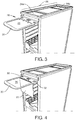
- the top flap 24 generally provides an upper enclosure for maintaining the dry ice compartment 20 in a closed configuration. When closed, the top flap 24 may also help define an upper working surface 26 of the trolley 10, as illustrated by FIG. 3 . When opened, the top flap 24 allows removal and replacement of a dry ice block (not shown).
- a single top flap 24 may be provided. This embodiment is illustrated by FIG. 2 .
- a double top flap (24a, 24b) may be provided as described further below, and as shown by FIGS. 3-8 .
- the trolley 10 When the trolley is in this configuration, it is useful for meal and beverage service.
- the trolley 10 maintains items contained within the trolley interior 12 in a chilled condition due to the dry ice compartment 20.
- the upper working surface 26 When the top flap 24 is closed, the upper working surface 26 may be used to hold drink bottles, cups, coffee carafes, stirrers, napkins, silverware, and any other beverage or meal service items.
- the trolley interior 12 may house or otherwise support food trays for meal service or bins 16 configured to hold soda cans, juice cans, water bottles, or any other appropriate service items.
- the trolley 10 may be converted to a waste trolley.
- a waste trolley it is desirable for the trolley interior 12 to be able to contain a trash bag or other waste receptacle. It is also desirable for trash to be inserted into the top of the trolley, rather than requiring the airline attendant to bend down in order to insert trash into the trolley interior.
- a sliding waste ring 28 is enabled.
- the sliding waste ring 28 is defined by an outer rim 30 and the dry ice compartment base 22.
- the rim 30 and base 22 are hingedly connected. Other connection options are possible, but it has been found that a hinged connection allows ease of use. However, it should be understood that a removable base or other moveable base is possible.
- the base 22 is hinged down and away from the outer rim 30.
- the outer rim 30 defines side notches 32 that may be used to secure and support a plastic waste bag 34.
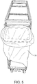
- an attendant may insert the waste bag 34 into the opening 36 defined by the outer rim 30. Edges of the waste bag may be secured against side notches 32. It should be understood that optional clips or additional securement features may be provided in order to maintain the waste bag in the desired position.
- FIG. 18 illustrates a waste ring 28 prior to being positioned with respect to a trolley. Rearward of the outer rim 30 is a securement portion 60.
- FIG. 19 for a full-size trolley, it is possible to use two adjacent waste rings 28 in order to use the trolley for waste collection on both sides. (It should be understood that a half-size trolley may use only a single waste ring 28.)
- the waste rings 28 may be positioned in slidable engagement with respect to the trolley 10 via side grooves 62 on the trolley. In use, a side edge 64 of the waste ring 28 may be received by the trolley side grooves 62 for slidable movement as shown by FIG. 19 .
- FIG. 20 illustrates the trolley of FIG. 19 with top flaps positioned over the waste rings.
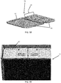
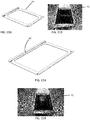
- FIG. 21A shows a perspective view of an alternate waste ring 80.
- Waste ring may be a separate waste ring that can be positioned within the opening of the trolley.
- FIG. 21B shows two separate waste rings 80 of FIG. 21A positioned in a trolley opening 82.
- FIG. 22A shows a perspective view of an alternate waste ring 80' that is larger than the waste ring of FIG. 21A .
- Waste ring 80' may be a separate waste ring that can be positioned within the opening of the trolley.
- FIG. 22B shows the waste ring 80' of FIG. 22A positioned in trolley opening 82.
- FIG. 7 illustrates a trolley version that has a double top flap 24a, 24b.
- the trolley door 40 is shown as closed, and a user is opening the double top flaps 24a, 24b in order to reveal access to the trolley interior which houses the waste bag 34. Opening of the top flaps 24a, 24b defines upper trash openings 42a, 42b. These upper trash openings 42a, 42b allow the user to insert trash directly into the top of the trolley, rather than into the side. Upper trash openings 42a, 42b also allow access to the interior of the trolley while the trolley door 40 is closed, providing an overall cleaner and more polished appearance to the trolley and trash collection process.
- FIGS. 8 and 20 both top flaps 24a, 24b have been opened and are resting along the trolley upper surface.
- FIG. 20 shows how the flaps may be positioned with respect to the slidable waste ring(s) 28 (without a waste bag in position).
- FIG. 8 shows the openable flaps in an open configuration (with a waste bag in place) so that a user may place trash within the trolley top portion.
- a central portion 44 between the flaps defines a surface onto which the top flaps 24a, 24b may be folded back onto. Once folded back, the surface 46 that was originally the lower surface of flaps now defines an upper working surface 48. Upper working surface 48 may be used to collect or store various other items.
- FIG. 9 shows a trolley embodiment that does not have a central portion 44, but instead, has double top flaps 24a, 24b that abut one another directly.
- each top flap defines an upper portion of a dry ice compartment 20.
- Each dry ice compartment 20 has a top flap 24 that may be independently opened, as illustrated by the right side of FIG. 10 .
- each dry ice compartment 20 may be hinged open as a whole compartment, as shown by the hinged compartment 20 on the left side of FIG. 10 .
- FIG. 23 illustrates a side cut away view of the trolley of FIG. 9 . Both dry ice compartments 20a, 20b are shown as closed.
- a central hinge 50 allows one of the dry ice compartments 20a to be rotated up and placed over a second dry ice compartment 20b, as illustrated by FIGS. 11 and 24 .
- This provides a single trash opening 42 in the upper portion of the trolley 10.
- Any of the sliding waste ring as described above may be used in this embodiment in order to support a waste bag positioned in the trolley interior. Alternatively, a separate waste ring may be used.
- the stacked dry ice compartments 20a, 20b may define a working surface 48 as shown in FIG. 24 .
- FIG. 11 illustrates the working surface 48 being used to support meal trays.
- FIG. 12 shows that even with a waste bag 34 positioned within the trolley interior 12, it is possible to stack trays 52 or bins below the trash bag 34.
- FIG. 13 illustrates that both dry ice compartments 20a, 20b may be completely removed if it is desirable to provide a trolley with a completely open top.
- This open top version is also applicable to a deep top trolley configuration.
- FIG. 14 illustrates a trolley embodiment that has a deep top with a dry ice compartment 20.
- the open top portion 56 may be used for other applications, as shown by FIGS. 15 and 16 .
- a single rear dry ice compartment 20 (or a second dry ice compartment 20b rotated back and over a first dry ice compartment 20a) is provided, and a deep drawer or bin 54 is positioned in the available open space 56 (shown by FIG. 14 ).
- FIG. 16 illustrates an alternate embodiment in which appliances such as a coffee machine or a beer tap or a meal dispenser may be positioned.
- FIG. 17 illustrates various options of space usages for the convertible trolleys 10 described herein.
- FIG. 17A two upper trolleys halves are used for waste collection and the two lower trolley halves are used for tray storage.
- FIG. 17B one trolley half is used for waste storage and a second trolley half is used for tray storage.
- FIG. 17C two complete trolley halves are both used for waste storage.
- FIGS. 25 and 26 various types of dividers may be used in order to help convert the trolley for various uses.
- a X-shaped divider 70 may be used when the upper trolley is to be used differently than the lower half of the trolley.
Landscapes
- Engineering & Computer Science (AREA)
- Mechanical Engineering (AREA)
- Chemical & Material Sciences (AREA)
- Aviation & Aerospace Engineering (AREA)
- Combustion & Propulsion (AREA)
- Transportation (AREA)
- Physics & Mathematics (AREA)
- Thermal Sciences (AREA)
- Chemical Kinetics & Catalysis (AREA)
- General Engineering & Computer Science (AREA)
- Refuse Collection And Transfer (AREA)
- Handcart (AREA)
Description
- The present invention relates generally to trolleys designed for use onboard passenger transportation vehicles. Trolleys of this type find particular, but not exclusive, use onboard aircraft.
- Passenger transportation vehicles such as aircraft often provide beverage and meal service to passengers. Airline attendants often wheel trolleys through aircraft aisles in order to offer various selections. These trolleys are often referred to as meal/drink or meal/beverage trolleys. These types of trolleys are generally provided with an interior compartment designed to support and receive one or more trays or slidable bins. Trolleys may be provided as full size trolleys or half size trolleys. The trolleys may be cooled via dry ice contained within the trolley (see for example
US2014/0021690 andUS2011/0278879 ). For example, an upper compartment may provide a storage place for dry ice in the top of the trolley. The dry ice compartment has a stationary base that supports the dry ice block. The dry ice may be accessible via a flap or a pull out tray (see for exampleUS2011/0278879 ). In other examples, an envelope or hollow cubby area is provided in the upper portion of the trolley and a dry ice block is slid therein. - Other types of trolleys are cooled in the galley using an air chiller system, such as an air over system (which function similar to a refrigerator) or an air through system (which blows cold air into the trolley). Such air over and air through systems do not have dry-ice drawers, but a deep top area. Once beverage and meal service is concluded, the meal/drink trolleys are stowed in the galley, and waste service begins.
- For waste collection, attendants may simply carry a plastic bag for collection of waste and other waste items. However, if meals were served on trays, then trays need to be collected as well. In order to facilitate waste collection as well as tray collection, a supported trash bag or trash bin may be positioned within the interior compartment. One example of such a bag is illustrated by
FIG. 27 , and is referred to as a flex-e-bag. In other examples, a foldable cardboard waste bin may be positioned within the interior compartment. An example of this embodiment is illustrated byFIG. 28 . In both instances, the top of the trolley provides a closed worktop that is used to collect trays. Trash is collected into the interior bin. However, the passengers have full view of the waste bin. This can be undesirable from a sanitary standpoint. The interior of these trolleys may not always be aesthetically pleasing. This design also requires that the attendants continually bend to insert trash into the lower part of the interior compartment. This is not ergonomically desirable and can lead to musculoskeletal strain injuries due to repetitive bending and kneeling. Further, the cardboard waste bins can be expensive, leading to higher recurring costs for the airline operator. Another challenge with using these types of trolleys for waste collection is that trays stacked too high on the top of the trolley can pose a safety hazard. However, if trays are stacked in the top of the interior compartment (above the waste bin), they may interfere with the waste collection process.US2014/0021690 discloses a cart having a pair of lids that open to allow access to the cart interior such that one side could contain hot food and the other side cold beverages or alternatively can be used as a waste collection unit after food and beverage service. When used for collecting and storing trash and recyclable materials the compartments may mount plastic bags. - In other examples, a specifically designed waste trolley may be used. Normally, a waste trolley has trash flaps in its top and may also have a trash flap in the door. These flaps can be opened in order to receive waste into the interior of the trolley compartment. A heavy waste bin or waste bag may be used inside the trolley. In this instance, two types of trolleys must be stored in the aircraft galley. The meal/drink trolley is used to serve food and drinks while the waste trolley sits empty and unused in the galley during beverage and meal service. It is only used during the second half of the process, for waste collection. This is undesirable from a logistical standpoint, as well as the time and cost that it is required to organize two different trolleys. The system also requires more room in the galley. This is space that could be used for other goals such as sales trolleys or more passenger seats. The additional trolleys also add to the weight of the aircraft. Accordingly, improvements are desirable. The improvements described herein are useable with any of the above-described types of trolleys (such as trolleys using a dry ice compartment, trolleys using an air over/air through system and having a deep top, full or half size trolleys) as well as with any other types of trolleys that would benefit from being convertible between service and waste collection trolleys.
- The present invention is as set out in the appended claims.
- Embodiments of the invention described herein thus provide systems and methods for providing trolleys that can be converted between a meal/beverage trolley and a waste collection trolley.
- The trolley interior may have internal ledges for supporting meal trays or bins or both. The trolley may have first and second dry ice compartments in hinged cooperation with one another. The first dry ice compartment may be hinged open and rest along a top portion of the second dry ice compartment. In an alternate example, if first and second dry ice compartments are provided, they may have a with a central portion therebetween, such that a first top flap of the first dry ice compartment and a second top flap of the second dry ice compartment are independently openable, and when in an open configuration, the top flaps lie against the central portion. It is possible for at least one dry ice compartment to be removable from the trolley. It is also possible to provide one or more bins that may be positioned within an open space defined by a removed or hinged dry ice compartment.
- In another example, there is provided a method, according to claim 11, for converting a meal/beverage trolley to a waste collection trolley.
-
-
FIG. 1 shows a front perspective view of a trolley in the meal/beverage service configuration -
FIG. 2 shows a top perspective view of an alternate trolley, having a single top flap. -
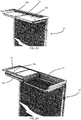
FIG. 3 a side perspective view of the trolley ofFIG. 1 with the sliding waste ring in its extended position. -
FIG. 4 is a side perspective view ofFIG. 3 , with the base hinged away from the outer rim of the sliding waste ring. -
FIG. 5 shows a front perspective view of a plastic waste bag positioned within an opening of the sliding waste ring. -
FIG. 6 shows a front perspective view ofFIG. 5 with the sliding waste ring positioned back within the trolley interior, with double top flaps in an open configuration. -
FIG. 7 shows a side perspective view of a trolley with the door closed and double top flaps in the process of being opened. -
FIG. 8 shows a side perspective view ofFIG. 7 , with the top flaps fully opened to define a work surface and to reveal trash openings. -
FIG. 9 shows a side perspective view of a trolley having top flaps separated via a hinge. -
FIG. 10 shows a side perspective view ofFIG. 9 , illustrating independent movement of a top flap or a complete dry ice compartment. -
FIG. 11 shows a perspective view of a trolley in a waste collection configuration, with stacked trays on an upper surface. -
FIG. 12 shows a front perspective view of a trolley and a waste collection configuration, with trays stacked in a lower portion of the trolley interior. -
FIG. 13 shows a side perspective view of a trolley with dry ice compartment completely removed. -
FIG. 14 shows a side perspective view of a trolley with a single dry ice compartment or with stacked/folded dry ice compartments, revealing an open space. -
FIG. 15 shows a side perspective view of a trolley having a bin or drawer positioned within the open space. In this image, the trolley door is open. -
FIG. 16 shows a side perspective view of a bin stacked above one or more dry ice compartments, and use of the open space for beverage machines. In this image, the trolley door is closed. -
FIG. 17A shows a side schematic view of a trolley and a waste collection configuration housing an upper waste bag and a lower tray storage portion in each half of the trolley.FIG. 17B shows a side schematic view of a trolley and a waste collection configuration housing a waste bag and one half of the trolley and tray storage in the other half trolley.FIG. 17C shows a side schematic view of a trolley and a waste collection configuration housing waste bags in both halves of the trolley. -
FIG. 18 shows a side perspective view of one example of a sliding waste ring, prior to being assembled with the trolley. -
FIG. 19 shows a side perspective view of a trolley having two sliding waste rings assembled with respect thereto. -
FIG. 20 shows a side perspective view of the trolley ofFIG. 19 having waste flaps in position and the base of the slidable waste ring in an open configuration. -
FIG. 21A shows a top plan view of an alternate embodiment of a waste ring.FIG. 21B shows two of the rings ofFIG. 21A positioned in a trolley. -
FIG. 22A shows a top plan view of an alternate embodiment of a waste ring.FIG. 22B shows the waste ring ofFIG. 22B positioned in a trolley. -
FIG. 23 shows a side perspective cut away view of the trolley ofFIG. 9 . -
FIG. 24 shows a side perspective cut away view of the trolley ofFIG. 11 . -
FIG. 25 shows a front perspective view of a trolley having an X-shaped divider. -
FIG. 26 shows a front perspective view of a trolley having an H-shaped bar divider. -
FIG. 27 shows a prior art meal trolley into which a Flex-e-bag is positioned. -
FIG. 28 shows a prior art meal trolley into which a cardboard waste collection bin is positioned. - Embodiments of the present invention provide a
combination trolley 10 with features that allow the trolley to be converted between a meal/drink trolley and a waste trolley. In a particular example, the upper portion of a meal/drink trolley has features that can be changed from a dry ice compartment to a waste ring. More particularly,FIG. 1 illustrates thetrolley 10 in its meal/drink configuration. In this figure, thetrolley door 40 is shown as being swung open in order to reveal thetrolley interior 12. In order to ease use as a meal or beverage trolley, there may be provided a series ofinternal ledges 14 that are configured to support one or more meal trays orbins 16.FIG. 1 illustrates abin 16 positioned within thetrolley interior 12, with bin edges resting on correspondingledges 14. Theupper portion 18 of this trolley version is provided with adry ice compartment 20. - Referring to
FIG. 2 , thedry ice compartment 20 is defined at least in part by abase 22 and a top flap 24 (which is shown as opened inFIG. 2 ). The base 22 generally provides a lower support for a dry ice block that may be positioned within thedry ice compartment 20. Thetop flap 24 generally provides an upper enclosure for maintaining thedry ice compartment 20 in a closed configuration. When closed, thetop flap 24 may also help define an upper workingsurface 26 of thetrolley 10, as illustrated byFIG. 3 . When opened, thetop flap 24 allows removal and replacement of a dry ice block (not shown). In some embodiments, a singletop flap 24 may be provided. This embodiment is illustrated byFIG. 2 . In other embodiments, a double top flap (24a, 24b) may be provided as described further below, and as shown byFIGS. 3-8 . - When the trolley is in this configuration, it is useful for meal and beverage service. For example, the
trolley 10 maintains items contained within thetrolley interior 12 in a chilled condition due to thedry ice compartment 20. When thetop flap 24 is closed, the upper workingsurface 26 may be used to hold drink bottles, cups, coffee carafes, stirrers, napkins, silverware, and any other beverage or meal service items. Thetrolley interior 12 may house or otherwise support food trays for meal service orbins 16 configured to hold soda cans, juice cans, water bottles, or any other appropriate service items. - Once the meal/beverage service has been completed, the
trolley 10 may be converted to a waste trolley. For use as a waste trolley, it is desirable for thetrolley interior 12 to be able to contain a trash bag or other waste receptacle. It is also desirable for trash to be inserted into the top of the trolley, rather than requiring the airline attendant to bend down in order to insert trash into the trolley interior. - In order to complete this conversion, a sliding
waste ring 28 is enabled. The slidingwaste ring 28 is defined by anouter rim 30 and the dryice compartment base 22. Therim 30 andbase 22 are hingedly connected. Other connection options are possible, but it has been found that a hinged connection allows ease of use. However, it should be understood that a removable base or other moveable base is possible. As illustrated byFIG. 4 , thebase 22 is hinged down and away from theouter rim 30. Theouter rim 30 definesside notches 32 that may be used to secure and support aplastic waste bag 34. As illustrated byFIG. 5 , an attendant may insert thewaste bag 34 into theopening 36 defined by theouter rim 30. Edges of the waste bag may be secured againstside notches 32. It should be understood that optional clips or additional securement features may be provided in order to maintain the waste bag in the desired position. - The sliding
waste ring 28 may cooperate within internal grooves of thetrolley interior 12.FIG. 18 illustrates awaste ring 28 prior to being positioned with respect to a trolley. Rearward of theouter rim 30 is asecurement portion 60. As illustrated byFIG. 19 , for a full-size trolley, it is possible to use two adjacent waste rings 28 in order to use the trolley for waste collection on both sides. (It should be understood that a half-size trolley may use only asingle waste ring 28.) The waste rings 28 may be positioned in slidable engagement with respect to thetrolley 10 viaside grooves 62 on the trolley. In use, aside edge 64 of thewaste ring 28 may be received by thetrolley side grooves 62 for slidable movement as shown byFIG. 19 .FIG. 20 illustrates the trolley ofFIG. 19 with top flaps positioned over the waste rings. -
FIG. 21A shows a perspective view of analternate waste ring 80. Waste ring may be a separate waste ring that can be positioned within the opening of the trolley.FIG. 21B shows two separate waste rings 80 ofFIG. 21A positioned in atrolley opening 82.FIG. 22A shows a perspective view of an alternate waste ring 80' that is larger than the waste ring ofFIG. 21A . Waste ring 80' may be a separate waste ring that can be positioned within the opening of the trolley.FIG. 22B shows the waste ring 80' ofFIG. 22A positioned introlley opening 82. - Once the
waste bag 34 has been positioned within theopening 36 of the slidingwaste ring 28, the slidingwaste ring 28 is pushed back into the trolley body, as illustrated byFIG. 6 .FIG. 7 illustrates a trolley version that has a doubletop flap trolley door 40 is shown as closed, and a user is opening the doubletop flaps waste bag 34. Opening of thetop flaps upper trash openings 42a, 42b. Theseupper trash openings 42a, 42b allow the user to insert trash directly into the top of the trolley, rather than into the side.Upper trash openings 42a, 42b also allow access to the interior of the trolley while thetrolley door 40 is closed, providing an overall cleaner and more polished appearance to the trolley and trash collection process. - In
FIGS. 8 and20 , bothtop flaps FIG. 20 shows how the flaps may be positioned with respect to the slidable waste ring(s) 28 (without a waste bag in position).FIG. 8 shows the openable flaps in an open configuration (with a waste bag in place) so that a user may place trash within the trolley top portion. - A
central portion 44 between the flaps defines a surface onto which thetop flaps surface 46 that was originally the lower surface of flaps now defines an upper workingsurface 48. Upper workingsurface 48 may be used to collect or store various other items. -
FIG. 9 shows a trolley embodiment that does not have acentral portion 44, but instead, has doubletop flaps FIG. 10 , each top flap defines an upper portion of adry ice compartment 20. Eachdry ice compartment 20 has atop flap 24 that may be independently opened, as illustrated by the right side ofFIG. 10 . Additionally, eachdry ice compartment 20 may be hinged open as a whole compartment, as shown by the hingedcompartment 20 on the left side ofFIG. 10 .FIG. 23 illustrates a side cut away view of the trolley ofFIG. 9 . Bothdry ice compartments central hinge 50 allows one of thedry ice compartments 20a to be rotated up and placed over a seconddry ice compartment 20b, as illustrated byFIGS. 11 and24 . This provides asingle trash opening 42 in the upper portion of thetrolley 10. Any of the sliding waste ring as described above may be used in this embodiment in order to support a waste bag positioned in the trolley interior. Alternatively, a separate waste ring may be used. The stackeddry ice compartments surface 48 as shown inFIG. 24 .FIG. 11 illustrates the workingsurface 48 being used to support meal trays. -
FIG. 12 shows that even with awaste bag 34 positioned within thetrolley interior 12, it is possible to stacktrays 52 or bins below thetrash bag 34. -
FIG. 13 illustrates that bothdry ice compartments -
FIG. 14 illustrates a trolley embodiment that has a deep top with adry ice compartment 20. In this example, the opentop portion 56 may be used for other applications, as shown byFIGS. 15 and 16 . For example, inFIG. 15 , a single rear dry ice compartment 20 (or a seconddry ice compartment 20b rotated back and over a firstdry ice compartment 20a) is provided, and a deep drawer orbin 54 is positioned in the available open space 56 (shown byFIG. 14 ). This creates a deep top panel that can allow an ergonomic workspace for flight attendants, defining a space for larger bottles or packages to be positioned.FIG. 16 illustrates an alternate embodiment in which appliances such as a coffee machine or a beer tap or a meal dispenser may be positioned. -
FIG. 17 illustrates various options of space usages for theconvertible trolleys 10 described herein. InFIG. 17A , two upper trolleys halves are used for waste collection and the two lower trolley halves are used for tray storage. InFIG. 17B , one trolley half is used for waste storage and a second trolley half is used for tray storage. InFIG. 17C , two complete trolley halves are both used for waste storage. It should be understood that these examples are shown for illustration only and other options are possible and considered within the scope of this disclosure. As shown byFIGS. 25 and 26 , various types of dividers may be used in order to help convert the trolley for various uses. For example, aX-shaped divider 70 may be used when the upper trolley is to be used differently than the lower half of the trolley. Alternatively, it is possible to use an H-shapeddivider 72. - It is possible to provide various additional accessories that assist with the meal service/trash collection processes. For example, it is possible to provide a cup stacking/collecting tube associated with the trolley, a liquid collector or separator, a recycling system, a tilting waste bin, or any combination thereof.
Claims (11)
- A trolley (10) configured to be convertible between meal/beverage service and waste collection service, the trolley (10) comprising:at least one dry ice compartment (20) defined by a top flap (24) and a dry ice compartment base (22),and characterized in further comprisinga sliding waste ring (28) defined by an outer rim (30) and the dry ice compartment base (22), the outer rim (30) and the dry ice compartment base (22) being hingedly cooperable such that when the waste ring (28) is extended from the trolley (10) and the dry ice compartment base (22) is hinged away from the outer rim (30), an opening (36) is defined by the outer rim (30) configured to support a waste bag, wherein when the top flap (24) is opened, a trash opening (36) is defined in an upper portion of the trolley.
- A trolley (10) as claimed in Claim 1, wherein the sliding waste ring (28) is configured to maintain its securement within the trolley (10).
- A trolley (10) as claimed in Claim 1 or Claim 2, wherein the sliding waste ring (28) comprises side notches (32) for securement of a waste bag.
- A trolley (10) as claimed in any of Claims 1 to 3, wherein the trolley comprises a trolley interior (12) comprising internal ledges (14) for supporting meal trays or bins or both.
- A trolley (10) as claimed in any of Claims 1 to 4, wherein the trolley (10) comprises first and second dry ice compartments (20a,20b) in hinged cooperation with one another.
- A trolley (10) as claimed in Claim 5, wherein the first dry ice compartment (20a) may be hinged open and rest along a top portion of the second dry ice compartment (20b).
- A trolley (10) as claimed in any of Claims 1 to 6, wherein the trolley (10) comprises first and second top flaps (24a, 24b) with a central portion (44) therebetween, such that the first top flap (24a) and second top flap (24b) are independently openable, and when in an open configuration, the top flaps (24a,24b) lie against the central portion (44).
- A trolley (10) as claimed in Claim 7, wherein the first top flap is a top flap for a first dry ice compartment and the second top flap is a top flap for a second dry ice compartment.
- A trolley (10) as claimed in any of Claims 1 to 8, wherein the at least one dry ice compartment (20) is removable from the trolley.
- A trolley (10) as claimed in any of Claims 1 to 9, further comprising one or more bins (54) that may be positioned within an open space (56) defined by a removed or hinged dry ice compartment (20; 20b,20a).
- A method for converting a meal/beverage trolley (10) to a waste collection trolley, comprising:providing a trolley (10) as claimed in any preceding claim,sliding the sliding waste ring (28) out from the trolley,hinging the dry ice compartment base (22) away from the outer rim (30) of the sliding waste ring (28),positioning a waste bag (34) within the opening (36) of the sliding waste ring (28),sliding the sliding waste ring (28) back into the trolley (10),opening the top flap (24) to define a trash opening (36) at an upper portion of the trolley (10).
Applications Claiming Priority (1)
| Application Number | Priority Date | Filing Date | Title |
|---|---|---|---|
| US201762485424P | 2017-04-14 | 2017-04-14 |
Publications (2)
| Publication Number | Publication Date |
|---|---|
| EP3388340A1 EP3388340A1 (en) | 2018-10-17 |
| EP3388340B1 true EP3388340B1 (en) | 2020-08-26 |
Family
ID=61972436
Family Applications (1)
| Application Number | Title | Priority Date | Filing Date |
|---|---|---|---|
| EP18167199.1A Not-in-force EP3388340B1 (en) | 2017-04-14 | 2018-04-13 | Meal/beverage trolley convertible to waste trolley |
Country Status (4)
| Country | Link |
|---|---|
| US (1) | US10427791B2 (en) |
| EP (1) | EP3388340B1 (en) |
| CN (1) | CN108720292B (en) |
| SG (1) | SG10201803132SA (en) |
Families Citing this family (11)
| Publication number | Priority date | Publication date | Assignee | Title |
|---|---|---|---|---|
| US10005482B2 (en) * | 2015-11-18 | 2018-06-26 | The Boeing Company | Cart apparatus and methods for use |
| CN110248846B (en) * | 2017-01-04 | 2020-10-30 | 上海延锋金桥汽车饰件系统有限公司 | Vehicle interior component |
| AU201716528S (en) * | 2017-10-27 | 2017-11-15 | Comfortel Furniture Pty Ltd | Trolley |
| USD929066S1 (en) * | 2019-10-16 | 2021-08-24 | Cambro Manufacturing Company | Narrow food service container |
| USD927816S1 (en) * | 2019-10-28 | 2021-08-10 | Cambro Manufacturing Company | Insulated food service container |
| CN111602965A (en) * | 2020-05-27 | 2020-09-01 | 上海明略人工智能(集团)有限公司 | Tableware recycling cart and control method thereof |
| CN113264190B (en) * | 2021-06-24 | 2024-11-26 | 苏州鹭翔航空设备有限公司 | A universal aviation trolley |
| WO2024104578A1 (en) * | 2022-11-17 | 2024-05-23 | Safran Cabin Catering B.V. | Trolley |
| EP4484864A1 (en) * | 2023-06-30 | 2025-01-01 | Airbus Operations GmbH | Passive cooling unit for cooling food, food storage container comprising the passive cooling unit, and aircraft comprising a galley and at least one such food storage container |
| EP4559812A1 (en) * | 2023-11-21 | 2025-05-28 | B/E Aerospace (UK) Limited | Retainer |
| US12365378B2 (en) * | 2024-11-08 | 2025-07-22 | Xiaojun LIANG | Foldable cart |
Family Cites Families (7)
| Publication number | Priority date | Publication date | Assignee | Title |
|---|---|---|---|---|
| AU3756295A (en) | 1995-10-19 | 1997-05-07 | Klm Catering Services Schiphol B.V. | A device and a method for treating catering containers to be used in aircraft |
| FR2877551B1 (en) * | 2004-11-05 | 2009-04-17 | Bernard Balkou | TROLLEY-TYPE ROLLING DEVICE FOR TRANSPORTING, DISPENSING AND RECOVERING WASTE |
| GB2480370B (en) * | 2010-05-14 | 2017-03-29 | Norduyn Inc | Body reinforcement and method of manufacturing thereof |
| FI20106098A0 (en) * | 2010-10-25 | 2010-10-25 | Jarmo Aurekoski | Aircraft serving trolley cooling solution |
| GB201206108D0 (en) * | 2012-04-05 | 2012-05-16 | Galimberti Massimo | Max recycle |
| EP2676880B1 (en) * | 2012-06-18 | 2018-05-02 | Airbus Operations GmbH | On-board passive protection device |
| US8936260B2 (en) * | 2012-07-20 | 2015-01-20 | B/E Aerospace, Inc. | Meal cart for an aircraft galley |
-
2018
- 2018-04-13 EP EP18167199.1A patent/EP3388340B1/en not_active Not-in-force
- 2018-04-13 CN CN201810332579.XA patent/CN108720292B/en active Active
- 2018-04-13 US US15/952,291 patent/US10427791B2/en active Active
- 2018-04-13 SG SG10201803132SA patent/SG10201803132SA/en unknown
Non-Patent Citations (1)
| Title |
|---|
| None * |
Also Published As
| Publication number | Publication date |
|---|---|
| CN108720292B (en) | 2022-07-12 |
| US10427791B2 (en) | 2019-10-01 |
| US20180297706A1 (en) | 2018-10-18 |
| SG10201803132SA (en) | 2018-11-29 |
| CN108720292A (en) | 2018-11-02 |
| EP3388340A1 (en) | 2018-10-17 |
Similar Documents
| Publication | Publication Date | Title |
|---|---|---|
| US10427791B2 (en) | Meal/beverage trolley convertible to waste trolley | |
| US8936260B2 (en) | Meal cart for an aircraft galley | |
| US11505224B2 (en) | Stackable rolling coolers with affixed main bin | |
| US5244220A (en) | Portable recycling and work center | |
| US9877577B2 (en) | Storage and serving cart | |
| CN104185594B (en) | The board galley improved | |
| CN108883869B (en) | Soft Sided Insulated Containers with Lid Fittings | |
| US9302440B2 (en) | Trash compactor trolleys and systems for use on commercial aircraft having mobile and stationary usage | |
| JP6001579B2 (en) | Vehicle console box | |
| US11273915B2 (en) | Modular refreshment center | |
| US9872808B2 (en) | Medications dispensing cart | |
| US20090242717A1 (en) | Cup Holder | |
| WO2023084420A1 (en) | Food and beverage carrier | |
| US12304634B2 (en) | Modular refreshment center | |
| US20060076744A1 (en) | Versatile sorting cart | |
| US20190071240A1 (en) | Food wrap organizer and storage bag dispenser | |
| US20250381917A1 (en) | Storage system for a motor vehicle with a plurality of system inserts with the same external geometry and motor vehicle with such a storage system | |
| US20210284340A1 (en) | Aircraft galley unit | |
| US8713953B1 (en) | Salad carrier | |
| KR200473765Y1 (en) | Multi cup holder | |
| US20250197007A1 (en) | Portable insert | |
| WO1992013471A1 (en) | Food carrying case and removable tub insert therefor | |
| KR20100006177U (en) | Console-accepting place for bus | |
| CN120303185A (en) | Top assembly for aircraft cabin waste collection and sorting trolleys | |
| CN113264190B (en) | A universal aviation trolley |
Legal Events
| Date | Code | Title | Description |
|---|---|---|---|
| PUAI | Public reference made under article 153(3) epc to a published international application that has entered the european phase |
Free format text: ORIGINAL CODE: 0009012 |
|
| STAA | Information on the status of an ep patent application or granted ep patent |
Free format text: STATUS: THE APPLICATION HAS BEEN PUBLISHED |
|
| AK | Designated contracting states |
Kind code of ref document: A1 Designated state(s): AL AT BE BG CH CY CZ DE DK EE ES FI FR GB GR HR HU IE IS IT LI LT LU LV MC MK MT NL NO PL PT RO RS SE SI SK SM TR |
|
| AX | Request for extension of the european patent |
Extension state: BA ME |
|
| STAA | Information on the status of an ep patent application or granted ep patent |
Free format text: STATUS: REQUEST FOR EXAMINATION WAS MADE |
|
| 17P | Request for examination filed |
Effective date: 20190409 |
|
| RBV | Designated contracting states (corrected) |
Designated state(s): AL AT BE BG CH CY CZ DE DK EE ES FI FR GB GR HR HU IE IS IT LI LT LU LV MC MK MT NL NO PL PT RO RS SE SI SK SM TR |
|
| STAA | Information on the status of an ep patent application or granted ep patent |
Free format text: STATUS: EXAMINATION IS IN PROGRESS |
|
| 17Q | First examination report despatched |
Effective date: 20190903 |
|
| GRAP | Despatch of communication of intention to grant a patent |
Free format text: ORIGINAL CODE: EPIDOSNIGR1 |
|
| STAA | Information on the status of an ep patent application or granted ep patent |
Free format text: STATUS: GRANT OF PATENT IS INTENDED |
|
| INTG | Intention to grant announced |
Effective date: 20200323 |
|
| GRAS | Grant fee paid |
Free format text: ORIGINAL CODE: EPIDOSNIGR3 |
|
| GRAA | (expected) grant |
Free format text: ORIGINAL CODE: 0009210 |
|
| STAA | Information on the status of an ep patent application or granted ep patent |
Free format text: STATUS: THE PATENT HAS BEEN GRANTED |
|
| AK | Designated contracting states |
Kind code of ref document: B1 Designated state(s): AL AT BE BG CH CY CZ DE DK EE ES FI FR GB GR HR HU IE IS IT LI LT LU LV MC MK MT NL NO PL PT RO RS SE SI SK SM TR |
|
| REG | Reference to a national code |
Ref country code: GB Ref legal event code: FG4D |
|
| REG | Reference to a national code |
Ref country code: CH Ref legal event code: EP |
|
| REG | Reference to a national code |
Ref country code: AT Ref legal event code: REF Ref document number: 1306135 Country of ref document: AT Kind code of ref document: T Effective date: 20200915 |
|
| REG | Reference to a national code |
Ref country code: IE Ref legal event code: FG4D |
|
| REG | Reference to a national code |
Ref country code: DE Ref legal event code: R096 Ref document number: 602018007184 Country of ref document: DE |
|
| REG | Reference to a national code |
Ref country code: LT Ref legal event code: MG4D |
|
| PG25 | Lapsed in a contracting state [announced via postgrant information from national office to epo] |
Ref country code: NO Free format text: LAPSE BECAUSE OF FAILURE TO SUBMIT A TRANSLATION OF THE DESCRIPTION OR TO PAY THE FEE WITHIN THE PRESCRIBED TIME-LIMIT Effective date: 20201126 Ref country code: GR Free format text: LAPSE BECAUSE OF FAILURE TO SUBMIT A TRANSLATION OF THE DESCRIPTION OR TO PAY THE FEE WITHIN THE PRESCRIBED TIME-LIMIT Effective date: 20201127 Ref country code: SE Free format text: LAPSE BECAUSE OF FAILURE TO SUBMIT A TRANSLATION OF THE DESCRIPTION OR TO PAY THE FEE WITHIN THE PRESCRIBED TIME-LIMIT Effective date: 20200826 Ref country code: BG Free format text: LAPSE BECAUSE OF FAILURE TO SUBMIT A TRANSLATION OF THE DESCRIPTION OR TO PAY THE FEE WITHIN THE PRESCRIBED TIME-LIMIT Effective date: 20201126 Ref country code: LT Free format text: LAPSE BECAUSE OF FAILURE TO SUBMIT A TRANSLATION OF THE DESCRIPTION OR TO PAY THE FEE WITHIN THE PRESCRIBED TIME-LIMIT Effective date: 20200826 Ref country code: PT Free format text: LAPSE BECAUSE OF FAILURE TO SUBMIT A TRANSLATION OF THE DESCRIPTION OR TO PAY THE FEE WITHIN THE PRESCRIBED TIME-LIMIT Effective date: 20201228 Ref country code: HR Free format text: LAPSE BECAUSE OF FAILURE TO SUBMIT A TRANSLATION OF THE DESCRIPTION OR TO PAY THE FEE WITHIN THE PRESCRIBED TIME-LIMIT Effective date: 20200826 Ref country code: FI Free format text: LAPSE BECAUSE OF FAILURE TO SUBMIT A TRANSLATION OF THE DESCRIPTION OR TO PAY THE FEE WITHIN THE PRESCRIBED TIME-LIMIT Effective date: 20200826 |
|
| REG | Reference to a national code |
Ref country code: NL Ref legal event code: MP Effective date: 20200826 |
|
| REG | Reference to a national code |
Ref country code: AT Ref legal event code: MK05 Ref document number: 1306135 Country of ref document: AT Kind code of ref document: T Effective date: 20200826 |
|
| PG25 | Lapsed in a contracting state [announced via postgrant information from national office to epo] |
Ref country code: NL Free format text: LAPSE BECAUSE OF FAILURE TO SUBMIT A TRANSLATION OF THE DESCRIPTION OR TO PAY THE FEE WITHIN THE PRESCRIBED TIME-LIMIT Effective date: 20200826 Ref country code: PL Free format text: LAPSE BECAUSE OF FAILURE TO SUBMIT A TRANSLATION OF THE DESCRIPTION OR TO PAY THE FEE WITHIN THE PRESCRIBED TIME-LIMIT Effective date: 20200826 Ref country code: RS Free format text: LAPSE BECAUSE OF FAILURE TO SUBMIT A TRANSLATION OF THE DESCRIPTION OR TO PAY THE FEE WITHIN THE PRESCRIBED TIME-LIMIT Effective date: 20200826 Ref country code: LV Free format text: LAPSE BECAUSE OF FAILURE TO SUBMIT A TRANSLATION OF THE DESCRIPTION OR TO PAY THE FEE WITHIN THE PRESCRIBED TIME-LIMIT Effective date: 20200826 Ref country code: IS Free format text: LAPSE BECAUSE OF FAILURE TO SUBMIT A TRANSLATION OF THE DESCRIPTION OR TO PAY THE FEE WITHIN THE PRESCRIBED TIME-LIMIT Effective date: 20201226 |
|
| PG25 | Lapsed in a contracting state [announced via postgrant information from national office to epo] |
Ref country code: SM Free format text: LAPSE BECAUSE OF FAILURE TO SUBMIT A TRANSLATION OF THE DESCRIPTION OR TO PAY THE FEE WITHIN THE PRESCRIBED TIME-LIMIT Effective date: 20200826 Ref country code: RO Free format text: LAPSE BECAUSE OF FAILURE TO SUBMIT A TRANSLATION OF THE DESCRIPTION OR TO PAY THE FEE WITHIN THE PRESCRIBED TIME-LIMIT Effective date: 20200826 Ref country code: CZ Free format text: LAPSE BECAUSE OF FAILURE TO SUBMIT A TRANSLATION OF THE DESCRIPTION OR TO PAY THE FEE WITHIN THE PRESCRIBED TIME-LIMIT Effective date: 20200826 Ref country code: DK Free format text: LAPSE BECAUSE OF FAILURE TO SUBMIT A TRANSLATION OF THE DESCRIPTION OR TO PAY THE FEE WITHIN THE PRESCRIBED TIME-LIMIT Effective date: 20200826 Ref country code: EE Free format text: LAPSE BECAUSE OF FAILURE TO SUBMIT A TRANSLATION OF THE DESCRIPTION OR TO PAY THE FEE WITHIN THE PRESCRIBED TIME-LIMIT Effective date: 20200826 |
|
| REG | Reference to a national code |
Ref country code: DE Ref legal event code: R097 Ref document number: 602018007184 Country of ref document: DE |
|
| PG25 | Lapsed in a contracting state [announced via postgrant information from national office to epo] |
Ref country code: ES Free format text: LAPSE BECAUSE OF FAILURE TO SUBMIT A TRANSLATION OF THE DESCRIPTION OR TO PAY THE FEE WITHIN THE PRESCRIBED TIME-LIMIT Effective date: 20200826 Ref country code: AL Free format text: LAPSE BECAUSE OF FAILURE TO SUBMIT A TRANSLATION OF THE DESCRIPTION OR TO PAY THE FEE WITHIN THE PRESCRIBED TIME-LIMIT Effective date: 20200826 Ref country code: AT Free format text: LAPSE BECAUSE OF FAILURE TO SUBMIT A TRANSLATION OF THE DESCRIPTION OR TO PAY THE FEE WITHIN THE PRESCRIBED TIME-LIMIT Effective date: 20200826 |
|
| PG25 | Lapsed in a contracting state [announced via postgrant information from national office to epo] |
Ref country code: SK Free format text: LAPSE BECAUSE OF FAILURE TO SUBMIT A TRANSLATION OF THE DESCRIPTION OR TO PAY THE FEE WITHIN THE PRESCRIBED TIME-LIMIT Effective date: 20200826 |
|
| PLBE | No opposition filed within time limit |
Free format text: ORIGINAL CODE: 0009261 |
|
| STAA | Information on the status of an ep patent application or granted ep patent |
Free format text: STATUS: NO OPPOSITION FILED WITHIN TIME LIMIT |
|
| 26N | No opposition filed |
Effective date: 20210527 |
|
| PG25 | Lapsed in a contracting state [announced via postgrant information from national office to epo] |
Ref country code: SI Free format text: LAPSE BECAUSE OF FAILURE TO SUBMIT A TRANSLATION OF THE DESCRIPTION OR TO PAY THE FEE WITHIN THE PRESCRIBED TIME-LIMIT Effective date: 20200826 |
|
| PG25 | Lapsed in a contracting state [announced via postgrant information from national office to epo] |
Ref country code: MC Free format text: LAPSE BECAUSE OF FAILURE TO SUBMIT A TRANSLATION OF THE DESCRIPTION OR TO PAY THE FEE WITHIN THE PRESCRIBED TIME-LIMIT Effective date: 20200826 |
|
| PG25 | Lapsed in a contracting state [announced via postgrant information from national office to epo] |
Ref country code: LU Free format text: LAPSE BECAUSE OF NON-PAYMENT OF DUE FEES Effective date: 20210413 |
|
| REG | Reference to a national code |
Ref country code: BE Ref legal event code: MM Effective date: 20210430 |
|
| PG25 | Lapsed in a contracting state [announced via postgrant information from national office to epo] |
Ref country code: CH Free format text: LAPSE BECAUSE OF NON-PAYMENT OF DUE FEES Effective date: 20210430 Ref country code: LI Free format text: LAPSE BECAUSE OF NON-PAYMENT OF DUE FEES Effective date: 20210430 |
|
| PG25 | Lapsed in a contracting state [announced via postgrant information from national office to epo] |
Ref country code: IE Free format text: LAPSE BECAUSE OF NON-PAYMENT OF DUE FEES Effective date: 20210413 |
|
| PG25 | Lapsed in a contracting state [announced via postgrant information from national office to epo] |
Ref country code: IS Free format text: LAPSE BECAUSE OF FAILURE TO SUBMIT A TRANSLATION OF THE DESCRIPTION OR TO PAY THE FEE WITHIN THE PRESCRIBED TIME-LIMIT Effective date: 20201226 |
|
| PG25 | Lapsed in a contracting state [announced via postgrant information from national office to epo] |
Ref country code: BE Free format text: LAPSE BECAUSE OF NON-PAYMENT OF DUE FEES Effective date: 20210430 |
|
| PGFP | Annual fee paid to national office [announced via postgrant information from national office to epo] |
Ref country code: FR Payment date: 20230321 Year of fee payment: 6 |
|
| PGFP | Annual fee paid to national office [announced via postgrant information from national office to epo] |
Ref country code: IT Payment date: 20230322 Year of fee payment: 6 |
|
| REG | Reference to a national code |
Ref country code: DE Ref legal event code: R081 Ref document number: 602018007184 Country of ref document: DE Owner name: SAFRAN CABIN CATERING B.V., NL Free format text: FORMER OWNER: DRIESSEN AEROSPACE GROUP N.V., ALKMAAR, NL |
|
| PG25 | Lapsed in a contracting state [announced via postgrant information from national office to epo] |
Ref country code: CY Free format text: LAPSE BECAUSE OF FAILURE TO SUBMIT A TRANSLATION OF THE DESCRIPTION OR TO PAY THE FEE WITHIN THE PRESCRIBED TIME-LIMIT Effective date: 20200826 |
|
| PG25 | Lapsed in a contracting state [announced via postgrant information from national office to epo] |
Ref country code: HU Free format text: LAPSE BECAUSE OF FAILURE TO SUBMIT A TRANSLATION OF THE DESCRIPTION OR TO PAY THE FEE WITHIN THE PRESCRIBED TIME-LIMIT; INVALID AB INITIO Effective date: 20180413 |
|
| REG | Reference to a national code |
Ref country code: GB Ref legal event code: 732E Free format text: REGISTERED BETWEEN 20240321 AND 20240327 |
|
| PG25 | Lapsed in a contracting state [announced via postgrant information from national office to epo] |
Ref country code: MK Free format text: LAPSE BECAUSE OF FAILURE TO SUBMIT A TRANSLATION OF THE DESCRIPTION OR TO PAY THE FEE WITHIN THE PRESCRIBED TIME-LIMIT Effective date: 20200826 |
|
| PGFP | Annual fee paid to national office [announced via postgrant information from national office to epo] |
Ref country code: GB Payment date: 20240423 Year of fee payment: 7 |
|
| PGFP | Annual fee paid to national office [announced via postgrant information from national office to epo] |
Ref country code: DE Payment date: 20240429 Year of fee payment: 7 |
|
| PG25 | Lapsed in a contracting state [announced via postgrant information from national office to epo] |
Ref country code: MT Free format text: LAPSE BECAUSE OF FAILURE TO SUBMIT A TRANSLATION OF THE DESCRIPTION OR TO PAY THE FEE WITHIN THE PRESCRIBED TIME-LIMIT Effective date: 20200826 |
|
| PG25 | Lapsed in a contracting state [announced via postgrant information from national office to epo] |
Ref country code: FR Free format text: LAPSE BECAUSE OF NON-PAYMENT OF DUE FEES Effective date: 20240430 |
|
| PG25 | Lapsed in a contracting state [announced via postgrant information from national office to epo] |
Ref country code: FR Free format text: LAPSE BECAUSE OF NON-PAYMENT OF DUE FEES Effective date: 20240430 |
|
| PG25 | Lapsed in a contracting state [announced via postgrant information from national office to epo] |
Ref country code: IT Free format text: LAPSE BECAUSE OF NON-PAYMENT OF DUE FEES Effective date: 20240413 |
|
| REG | Reference to a national code |
Ref country code: DE Ref legal event code: R119 Ref document number: 602018007184 Country of ref document: DE |
|
| PG25 | Lapsed in a contracting state [announced via postgrant information from national office to epo] |
Ref country code: TR Free format text: LAPSE BECAUSE OF FAILURE TO SUBMIT A TRANSLATION OF THE DESCRIPTION OR TO PAY THE FEE WITHIN THE PRESCRIBED TIME-LIMIT Effective date: 20200826 |
|
| GBPC | Gb: european patent ceased through non-payment of renewal fee |
Effective date: 20250413 |
|
| PG25 | Lapsed in a contracting state [announced via postgrant information from national office to epo] |
Ref country code: DE Free format text: LAPSE BECAUSE OF NON-PAYMENT OF DUE FEES Effective date: 20251104 |
|
| PG25 | Lapsed in a contracting state [announced via postgrant information from national office to epo] |
Ref country code: GB Free format text: LAPSE BECAUSE OF NON-PAYMENT OF DUE FEES Effective date: 20250413 |