EP3388298A1 - Automated vehicle open-loop brake control system - Google Patents
Automated vehicle open-loop brake control system Download PDFInfo
- Publication number
- EP3388298A1 EP3388298A1 EP18165663.8A EP18165663A EP3388298A1 EP 3388298 A1 EP3388298 A1 EP 3388298A1 EP 18165663 A EP18165663 A EP 18165663A EP 3388298 A1 EP3388298 A1 EP 3388298A1
- Authority
- EP
- European Patent Office
- Prior art keywords
- brake
- vehicle
- brakes
- pressure
- host
- Prior art date
- Legal status (The legal status is an assumption and is not a legal conclusion. Google has not performed a legal analysis and makes no representation as to the accuracy of the status listed.)
- Withdrawn
Links
Images

Classifications
-
- B—PERFORMING OPERATIONS; TRANSPORTING
- B60—VEHICLES IN GENERAL
- B60T—VEHICLE BRAKE CONTROL SYSTEMS OR PARTS THEREOF; BRAKE CONTROL SYSTEMS OR PARTS THEREOF, IN GENERAL; ARRANGEMENT OF BRAKING ELEMENTS ON VEHICLES IN GENERAL; PORTABLE DEVICES FOR PREVENTING UNWANTED MOVEMENT OF VEHICLES; VEHICLE MODIFICATIONS TO FACILITATE COOLING OF BRAKES
- B60T8/00—Arrangements for adjusting wheel-braking force to meet varying vehicular or ground-surface conditions, e.g. limiting or varying distribution of braking force
- B60T8/32—Arrangements for adjusting wheel-braking force to meet varying vehicular or ground-surface conditions, e.g. limiting or varying distribution of braking force responsive to a speed condition, e.g. acceleration or deceleration
- B60T8/58—Arrangements for adjusting wheel-braking force to meet varying vehicular or ground-surface conditions, e.g. limiting or varying distribution of braking force responsive to a speed condition, e.g. acceleration or deceleration responsive to speed and another condition or to plural speed conditions
-
- B—PERFORMING OPERATIONS; TRANSPORTING
- B60—VEHICLES IN GENERAL
- B60T—VEHICLE BRAKE CONTROL SYSTEMS OR PARTS THEREOF; BRAKE CONTROL SYSTEMS OR PARTS THEREOF, IN GENERAL; ARRANGEMENT OF BRAKING ELEMENTS ON VEHICLES IN GENERAL; PORTABLE DEVICES FOR PREVENTING UNWANTED MOVEMENT OF VEHICLES; VEHICLE MODIFICATIONS TO FACILITATE COOLING OF BRAKES
- B60T7/00—Brake-action initiating means
- B60T7/12—Brake-action initiating means for automatic initiation; for initiation not subject to will of driver or passenger
-
- B—PERFORMING OPERATIONS; TRANSPORTING
- B60—VEHICLES IN GENERAL
- B60T—VEHICLE BRAKE CONTROL SYSTEMS OR PARTS THEREOF; BRAKE CONTROL SYSTEMS OR PARTS THEREOF, IN GENERAL; ARRANGEMENT OF BRAKING ELEMENTS ON VEHICLES IN GENERAL; PORTABLE DEVICES FOR PREVENTING UNWANTED MOVEMENT OF VEHICLES; VEHICLE MODIFICATIONS TO FACILITATE COOLING OF BRAKES
- B60T8/00—Arrangements for adjusting wheel-braking force to meet varying vehicular or ground-surface conditions, e.g. limiting or varying distribution of braking force
- B60T8/17—Using electrical or electronic regulation means to control braking
-
- B—PERFORMING OPERATIONS; TRANSPORTING
- B60—VEHICLES IN GENERAL
- B60T—VEHICLE BRAKE CONTROL SYSTEMS OR PARTS THEREOF; BRAKE CONTROL SYSTEMS OR PARTS THEREOF, IN GENERAL; ARRANGEMENT OF BRAKING ELEMENTS ON VEHICLES IN GENERAL; PORTABLE DEVICES FOR PREVENTING UNWANTED MOVEMENT OF VEHICLES; VEHICLE MODIFICATIONS TO FACILITATE COOLING OF BRAKES
- B60T8/00—Arrangements for adjusting wheel-braking force to meet varying vehicular or ground-surface conditions, e.g. limiting or varying distribution of braking force
- B60T8/17—Using electrical or electronic regulation means to control braking
- B60T8/172—Determining control parameters used in the regulation, e.g. by calculations involving measured or detected parameters
-
- B—PERFORMING OPERATIONS; TRANSPORTING
- B60—VEHICLES IN GENERAL
- B60T—VEHICLE BRAKE CONTROL SYSTEMS OR PARTS THEREOF; BRAKE CONTROL SYSTEMS OR PARTS THEREOF, IN GENERAL; ARRANGEMENT OF BRAKING ELEMENTS ON VEHICLES IN GENERAL; PORTABLE DEVICES FOR PREVENTING UNWANTED MOVEMENT OF VEHICLES; VEHICLE MODIFICATIONS TO FACILITATE COOLING OF BRAKES
- B60T8/00—Arrangements for adjusting wheel-braking force to meet varying vehicular or ground-surface conditions, e.g. limiting or varying distribution of braking force
- B60T8/32—Arrangements for adjusting wheel-braking force to meet varying vehicular or ground-surface conditions, e.g. limiting or varying distribution of braking force responsive to a speed condition, e.g. acceleration or deceleration
- B60T8/321—Arrangements for adjusting wheel-braking force to meet varying vehicular or ground-surface conditions, e.g. limiting or varying distribution of braking force responsive to a speed condition, e.g. acceleration or deceleration deceleration
-
- B—PERFORMING OPERATIONS; TRANSPORTING
- B60—VEHICLES IN GENERAL
- B60T—VEHICLE BRAKE CONTROL SYSTEMS OR PARTS THEREOF; BRAKE CONTROL SYSTEMS OR PARTS THEREOF, IN GENERAL; ARRANGEMENT OF BRAKING ELEMENTS ON VEHICLES IN GENERAL; PORTABLE DEVICES FOR PREVENTING UNWANTED MOVEMENT OF VEHICLES; VEHICLE MODIFICATIONS TO FACILITATE COOLING OF BRAKES
- B60T2250/00—Monitoring, detecting, estimating vehicle conditions
Definitions
- This disclosure generally relates to a brake control system, and more particularly relates to a system that operates a brake-unit to an initial-pressure to initiate braking of a host-vehicle in accordance with a brake-model that characterizes vehicle-deceleration versus the initial-pressure based on a time-of-operation of the brakes.
- the braking-force or vehicle-deceleration response of a vehicle brake system varies for a particular value of brake-pressure, i.e. the hydraulic fluid pressure in the brake system. That is, for a given brake-pressure, the degree to which the vehicle decelerates varies. For example, it has been observed that in some instances warmed-up brakes stop faster than cold brakes, and over-heated brakes stop slower than warmed-up brakes. For automated-vehicles, this inconsistency may cause an undesirable fluctuation in deceleration that occupants of the automated-vehicle may find annoying.
- Described herein is a brake system that compensates or adjusts the initial open-loop brake pressure control based time-of-operation of the brakes. That is, the recommended initial-pressure is characterized for temperature effects on brake pressure vs. brake-temperature.
- the time-of-operation of the brakes may be used to estimate a brake-temperature.
- the brake-model may be used to estimate a braking-distance of the host-vehicle.
- an open-loop brake control system for an automated vehicle includes a brake-unit and a controller.
- the brake-unit varies brake-pressure to operate brakes of a host-vehicle.
- the controller is in communication with the brake-unit.
- the controller operates the brake-unit to an initial-pressure to initiate braking of the host-vehicle in accordance with a brake-model that characterizes vehicle-deceleration versus the initial-pressure based on a time-of-operation of the brakes.
- Fig. 1 illustrates a non-limiting example of an open-loop brake control system 10, hereafter referred to as the system 10.
- the system 10 is suitable for use by an automated vehicle, a host-vehicle 12 for example.
- the term automated vehicle may apply to instances when the host-vehicle 12 is being operated in an automated-mode 14, i.e. a fully autonomous mode, where a human-operator (not shown) of the host-vehicle 12 may do little more than designate a destination in order to operate the host-vehicle 12.
- full automation is not a requirement.
- the teachings presented herein are useful when the host-vehicle 12 is operated in a manual-mode 16 where the degree or level of automation may be to automatically operate the brakes to avoid a collision and/or control forward motion of the host-vehicle 12 during a traffic-jam where bumper-to-bumper traffic is present.
- the system 10 may include a global-positioning-system receiver (GPS receiver 18) that receives signals from satellites to determine a location of the host-vehicle 12 on a digital-map 20.
- GPS receiver 18 global-positioning-system receiver
- the system 10 may also include an object-detector 22 that may include, but is not limited to, one or any combination of a camera, radar, and/or lidar used to detect an object 24 such as another-vehicle or a stop-sign 52 ( Fig. 2 ) proximate to the host-vehicle 12.
- the system 10 includes a brake-unit 26 that varies brake-pressure 28, e.g. varies the hydraulic fluid-pressure applied to the brakes 30 if the brakes 30 are the hydraulic type, to operate the brakes 30 of a host-vehicle 12.
- the brake-unit 26 may include an electric-motor (not shown) that is used to generate the brake-pressure 28, as will be recognized by those in the art familiar with automatic braking.
- the brake-unit 26 may also include an anti-lock-braking feature that modulates the brake-pressure 28 when skidding or lock-up of one or more wheels of the host-vehicle 12 is detected.
- the system 10 includes a controller 32 in communication with the brake-unit 26.
- the communication may be by way of wires, optical-fiber, or wireless communications as will be recognized by those in the art.
- the controller 32 may include a processor (not specifically shown) such as a microprocessor or other control circuitry such as analog and/or digital control circuitry including an application specific integrated circuit (ASIC) for processing data as should be evident to those in the art.
- the controller 32 may include memory (not specifically shown), including non-volatile memory, such as electrically erasable programmable read-only memory (EEPROM) for storing one or more routines, thresholds, and captured data.
- the one or more routines may be executed by the processor to perform steps for operating the brake-unit 26 based on signals received by the controller 32 from the GPS receiver 18 and/or the object-detector 22 as described herein.
- the controller 32 is generally configured or programmed to operate the brake-unit 26 to an initial-pressure 34 to initiate braking of the host-vehicle 12.
- the initial-pressure 34 is selected or determined in accordance with a brake-model 36. It is noted that what value is selected as the initial-pressure 34 is commonly considered to be an open-loop selection because the selection is made without the benefit of a feed-back signal such as the vehicle-deceleration 38. Soon after the braking of the host-vehicle 12 begins, then the vehicle-deceleration 38 can be used to adjust the brake-pressure 28.
- the brake-model 36 includes a characterization or mathematical model of the vehicle-deceleration 38 versus the initial-pressure 34.
- the characterization may initially be a predetermined or preset characterization based on observation of multiple vehicles during development testing. That initial characterization may be updated as the host-vehicle 12 is operated so that the characterization is custom-tuned specifically for the host-vehicle 12. This self-calibration or self-tuning helps to minimize the need for occupant detectable changes (increases or decreases) in the brake-pressure 28 soon after braking begins.
- the characterization of the vehicle-deceleration 38 versus the initial-pressure 34 includes compensation based on a time-of-operation 40 of the brakes 30.
- the time-of-operation 40 measure of how much or often the brakes 30 have been used since the host-vehicle 12 was started or use of the host-vehicle 12 was initiated. For example, if the host-vehicle 12 is parked over-night, it has been observed that the vehicle-deceleration 38 is decreased for a given value of the initial-pressure 34 when the brakes 30 are first used in the morning.
- the brakes 30 warm-up and the vehicle-deceleration 38 is increased for a given value of the initial-pressure 34 when compared to when first time that day the brakes 30 were used.
- Fig. 2 illustrates a non-limiting example of the host-vehicle 12 traveling down-hill section of a roadway 50 and approaching a stop-sign 52.
- the down-hill section of the roadway 50 was relatively long, more than five kilometers (5km) for example, and the road-grade is relatively steep, more than eight percent (8%) for example, frequent use of the brakes 30 to maintain a safe and/or legal value of the vehicle-speed 54 may increase the brake-temperature 42 excessively and lead to brake-fade.
- the time-of-operation 40 optionally in combination with a profile of the brake-pressure 28 during the time-of-operation 40, may be used to estimate the brake-temperature 42 of the brakes 30. Knowledge of the brake-temperature 42 may be useful to make appropriate adjustments to the vehicle-deceleration 38 vs. initial-pressure 34 characteristic or profile.
- the system 10 may include the means to determine or receive an indication of the vehicle-speed 54, the road-grade 56, a vehicle-load 58, and other information useful to determine or estimate a braking-distance 60 of the host-vehicle 12.
- the road-grade 56 may be indicated by an inclinometer installed on the host-vehicle 12, or be indicated by the digital-map 20.
- the vehicle-load 58 may be indicated by height-sensors (not shown) coupled to suspension components of the host-vehicle 12.
- the determination or estimation of the braking-distance 60 may also consider historical use information from the brake-model 36 that measured the response of the brakes 30 in previous uses.
- the brakes 30 may be very sensitive, i.e. grabby, when first used. Accordingly, the system 10 may be configured or programmed to determine a parked-duration 62 so that the initial-pressure 34 can be adjusted to prevent excessive amounts of vehicle-deceleration 38 when the brakes 30 are first used when the parked-duration 62 is relatively long.
- the system 10 may be configured to momentarily operate the brakes 30 with a very low value of the brake-pressure 28 when use of the host-vehicle 12 is initiated for several reasons such as, but not limited to, check the function of the brakes, polish the friction-surfaces of the brakes 30 to prevent the aforementioned high sensitivity when the value of the parked-duration 62 is large, or just warm-up the brakes 30 to avoid an unexpectedly low value of the vehicle-deceleration 38 in response to some selected value of the initial-pressure 34. That is, the system may lightly 'ride' the brakes for a short distance, e.g. 0.1 km, to prepare the brakes for regular use to stop the host-vehicle 12.
- the system 10 may also be programmed or configured to determine when the brakes 30 need to be serviced, e.g. when the brake-pads need to be replaced.
- One indication of the need to service the brakes 30 is when brake-model 36 indicates that the initial-pressure 34 for a common situation (e.g. level roadway, the vehicle-speed between 35kph and 40kph) is greater than an initial-threshold (not shown). That is, if the initial-pressure 34 output by the brake-model 36 is excessive, and other factors of the system 10 such as the brake-temperature 42 are nominal, that may be an indication that the brakes 30 need to be serviced.
- the time-of-operation 40 in combination with a profile of the brake-pressure 28 during the time-of-operation 40 may be used to estimate brake-pad wear.
- an open-loop brake control system (the system 10), a controller 32 for the system 10, and a method of operating the system 10 is provided.
- the system 10 described herein is an improvement over prior automated braking systems because the system 10 includes the brake-model 36 that determines or maintains a history of the vehicle-deceleration 38 vs. the initial-pressure 34 of the brakes 30 so that unexpected adjustments to the brake-pressure 28 immediately or shortly after braking is initiated can be avoided. That is, because the vehicle-deceleration 38 vs. the initial-pressure 34 characteristic is tracked, the response of the brakes 30 can be confidently predicted, so the deceleration of the host-vehicle 12 experienced by an occupant or passenger of the host-vehicle 12 is smooth and not annoying to the passenger.
Landscapes
- Engineering & Computer Science (AREA)
- Transportation (AREA)
- Mechanical Engineering (AREA)
- Regulating Braking Force (AREA)
Abstract
An open-loop brake control system (10) for an automated vehicle includes a brake-unit (26) and a controller (32). The brake-unit (26) varies brake-pressure (28) to operate brakes (30) of a host-vehicle (12). The controller (32) is in communication with the brake-unit (26). The controller (32) operates the brake-unit (26) to an initial-pressure (34) to initiate braking of the host-vehicle (12) in accordance with a brake-model (36) that characterizes vehicle-deceleration (38) versus the initial-pressure (34) based on a time-of-operation (40) of the brakes (30).
Description
- This disclosure generally relates to a brake control system, and more particularly relates to a system that operates a brake-unit to an initial-pressure to initiate braking of a host-vehicle in accordance with a brake-model that characterizes vehicle-deceleration versus the initial-pressure based on a time-of-operation of the brakes.
- It has been observed that the braking-force or vehicle-deceleration response of a vehicle brake system varies for a particular value of brake-pressure, i.e. the hydraulic fluid pressure in the brake system. That is, for a given brake-pressure, the degree to which the vehicle decelerates varies. For example, it has been observed that in some instances warmed-up brakes stop faster than cold brakes, and over-heated brakes stop slower than warmed-up brakes. For automated-vehicles, this inconsistency may cause an undesirable fluctuation in deceleration that occupants of the automated-vehicle may find annoying.
- Described herein is a brake system that compensates or adjusts the initial open-loop brake pressure control based time-of-operation of the brakes. That is, the recommended initial-pressure is characterized for temperature effects on brake pressure vs. brake-temperature.
- The time-of-operation of the brakes may be used to estimate a brake-temperature. The brake-model may be used to estimate a braking-distance of the host-vehicle.
- In accordance with one embodiment, an open-loop brake control system for an automated vehicle is provided. The system includes a brake-unit and a controller. The brake-unit varies brake-pressure to operate brakes of a host-vehicle. The controller is in communication with the brake-unit. The controller operates the brake-unit to an initial-pressure to initiate braking of the host-vehicle in accordance with a brake-model that characterizes vehicle-deceleration versus the initial-pressure based on a time-of-operation of the brakes.
- Further features and advantages will appear more clearly on a reading of the following detailed description of the preferred embodiment, which is given by way of non-limiting example only and with reference to the accompanying drawings.
- The present invention will now be described, by way of example with reference to the accompanying drawings, in which:
-
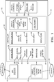
Fig. 1 is diagram of a brake control system in accordance with one embodiment; and -
Fig. 2 is an illustration of a host-vehicle equipped with the system ofFig. 1 traveling on a roadway in accordance with one embodiment. -
Fig. 1 illustrates a non-limiting example of an open-loopbrake control system 10, hereafter referred to as thesystem 10. In general, thesystem 10 is suitable for use by an automated vehicle, a host-vehicle 12 for example. As used herein, the term automated vehicle may apply to instances when the host-vehicle 12 is being operated in an automated-mode 14, i.e. a fully autonomous mode, where a human-operator (not shown) of the host-vehicle 12 may do little more than designate a destination in order to operate the host-vehicle 12. However, full automation is not a requirement. It is contemplated that the teachings presented herein are useful when the host-vehicle 12 is operated in a manual-mode 16 where the degree or level of automation may be to automatically operate the brakes to avoid a collision and/or control forward motion of the host-vehicle 12 during a traffic-jam where bumper-to-bumper traffic is present. - As will be recognized by those in the art, the
system 10 may include a global-positioning-system receiver (GPS receiver 18) that receives signals from satellites to determine a location of the host-vehicle 12 on a digital-map 20. Thesystem 10 may also include an object-detector 22 that may include, but is not limited to, one or any combination of a camera, radar, and/or lidar used to detect anobject 24 such as another-vehicle or a stop-sign 52 (Fig. 2 ) proximate to the host-vehicle 12. - The
system 10 includes a brake-unit 26 that varies brake-pressure 28, e.g. varies the hydraulic fluid-pressure applied to thebrakes 30 if thebrakes 30 are the hydraulic type, to operate thebrakes 30 of a host-vehicle 12. Alternatively, or in addition to the hydraulics, the brake-unit 26 may include an electric-motor (not shown) that is used to generate the brake-pressure 28, as will be recognized by those in the art familiar with automatic braking. The brake-unit 26 may also include an anti-lock-braking feature that modulates the brake-pressure 28 when skidding or lock-up of one or more wheels of the host-vehicle 12 is detected. - The
system 10 includes acontroller 32 in communication with the brake-unit 26. The communication may be by way of wires, optical-fiber, or wireless communications as will be recognized by those in the art. Thecontroller 32 may include a processor (not specifically shown) such as a microprocessor or other control circuitry such as analog and/or digital control circuitry including an application specific integrated circuit (ASIC) for processing data as should be evident to those in the art. Thecontroller 32 may include memory (not specifically shown), including non-volatile memory, such as electrically erasable programmable read-only memory (EEPROM) for storing one or more routines, thresholds, and captured data. The one or more routines may be executed by the processor to perform steps for operating the brake-unit 26 based on signals received by thecontroller 32 from theGPS receiver 18 and/or the object-detector 22 as described herein. - The
controller 32 is generally configured or programmed to operate the brake-unit 26 to an initial-pressure 34 to initiate braking of the host-vehicle 12. The initial-pressure 34 is selected or determined in accordance with a brake-model 36. It is noted that what value is selected as the initial-pressure 34 is commonly considered to be an open-loop selection because the selection is made without the benefit of a feed-back signal such as the vehicle-deceleration 38. Soon after the braking of the host-vehicle 12 begins, then the vehicle-deceleration 38 can be used to adjust the brake-pressure 28. However, it is preferable to avoid substantial changes (increases or decreases) in the brake-pressure 28 soon after braking begins as a substantial change in the brake-pressure 28 will likely be perceived by an occupant of the host-vehicle 12 and be an annoyance or cause discomfort to the occupant. - The brake-
model 36 includes a characterization or mathematical model of the vehicle-deceleration 38 versus the initial-pressure 34. The characterization may initially be a predetermined or preset characterization based on observation of multiple vehicles during development testing. That initial characterization may be updated as the host-vehicle 12 is operated so that the characterization is custom-tuned specifically for the host-vehicle 12. This self-calibration or self-tuning helps to minimize the need for occupant detectable changes (increases or decreases) in the brake-pressure 28 soon after braking begins. - As noted above, it has been observed that in some instances warmed-up brakes stop faster than cold brakes, and over-heated brakes stop slower than warmed-up brakes. Advantageously, the characterization of the vehicle-
deceleration 38 versus the initial-pressure 34 includes compensation based on a time-of-operation 40 of thebrakes 30. As used herein, the time-of-operation 40 measure of how much or often thebrakes 30 have been used since the host-vehicle 12 was started or use of the host-vehicle 12 was initiated. For example, if the host-vehicle 12 is parked over-night, it has been observed that the vehicle-deceleration 38 is decreased for a given value of the initial-pressure 34 when thebrakes 30 are first used in the morning. However, after a short distance (e.g. 5km) and a few operations of the brakes to slow the host-vehicle 12, thebrakes 30 warm-up and the vehicle-deceleration 38 is increased for a given value of the initial-pressure 34 when compared to when first time that day thebrakes 30 were used. -
Fig. 2 illustrates a non-limiting example of the host-vehicle 12 traveling down-hill section of aroadway 50 and approaching a stop-sign 52. As will be recognized by most, if the down-hill section of theroadway 50 was relatively long, more than five kilometers (5km) for example, and the road-grade is relatively steep, more than eight percent (8%) for example, frequent use of thebrakes 30 to maintain a safe and/or legal value of the vehicle-speed 54 may increase the brake-temperature 42 excessively and lead to brake-fade. It is contemplated that the time-of-operation 40, optionally in combination with a profile of the brake-pressure 28 during the time-of-operation 40, may be used to estimate the brake-temperature 42 of thebrakes 30. Knowledge of the brake-temperature 42 may be useful to make appropriate adjustments to the vehicle-deceleration 38 vs. initial-pressure 34 characteristic or profile. - Returning now to
Fig. 1 , It is contemplated that thesystem 10 may include the means to determine or receive an indication of the vehicle-speed 54, the road-grade 56, a vehicle-load 58, and other information useful to determine or estimate a braking-distance 60 of the host-vehicle 12. The road-grade 56 may be indicated by an inclinometer installed on the host-vehicle 12, or be indicated by the digital-map 20. The vehicle-load 58 may be indicated by height-sensors (not shown) coupled to suspension components of the host-vehicle 12. The determination or estimation of the braking-distance 60 may also consider historical use information from the brake-model 36 that measured the response of thebrakes 30 in previous uses. - It has been observed that after the host-
vehicle 12 has been parked for a long period of time, a week for example, thebrakes 30 may be very sensitive, i.e. grabby, when first used. Accordingly, thesystem 10 may be configured or programmed to determine a parked-duration 62 so that the initial-pressure 34 can be adjusted to prevent excessive amounts of vehicle-deceleration 38 when thebrakes 30 are first used when the parked-duration 62 is relatively long. It is also contemplated that thesystem 10 may be configured to momentarily operate thebrakes 30 with a very low value of the brake-pressure 28 when use of the host-vehicle 12 is initiated for several reasons such as, but not limited to, check the function of the brakes, polish the friction-surfaces of thebrakes 30 to prevent the aforementioned high sensitivity when the value of the parked-duration 62 is large, or just warm-up thebrakes 30 to avoid an unexpectedly low value of the vehicle-deceleration 38 in response to some selected value of the initial-pressure 34. That is, the system may lightly 'ride' the brakes for a short distance, e.g. 0.1 km, to prepare the brakes for regular use to stop the host-vehicle 12. - The
system 10 may also be programmed or configured to determine when thebrakes 30 need to be serviced, e.g. when the brake-pads need to be replaced. One indication of the need to service thebrakes 30 is when brake-model 36 indicates that the initial-pressure 34 for a common situation (e.g. level roadway, the vehicle-speed between 35kph and 40kph) is greater than an initial-threshold (not shown). That is, if the initial-pressure 34 output by the brake-model 36 is excessive, and other factors of thesystem 10 such as the brake-temperature 42 are nominal, that may be an indication that thebrakes 30 need to be serviced. Alternatively or additionally, the time-of-operation 40 in combination with a profile of the brake-pressure 28 during the time-of-operation 40 may be used to estimate brake-pad wear. - Accordingly, an open-loop brake control system (the system 10), a
controller 32 for thesystem 10, and a method of operating thesystem 10 is provided. Thesystem 10 described herein is an improvement over prior automated braking systems because thesystem 10 includes the brake-model 36 that determines or maintains a history of the vehicle-deceleration 38 vs. the initial-pressure 34 of thebrakes 30 so that unexpected adjustments to the brake-pressure 28 immediately or shortly after braking is initiated can be avoided. That is, because the vehicle-deceleration 38 vs. the initial-pressure 34 characteristic is tracked, the response of thebrakes 30 can be confidently predicted, so the deceleration of the host-vehicle 12 experienced by an occupant or passenger of the host-vehicle 12 is smooth and not annoying to the passenger. - While this invention has been described in terms of the preferred embodiments thereof, it is not intended to be so limited, but rather only to the extent set forth in the claims that follow.
Claims (3)
- An open-loop brake control system (10) for an automated vehicle, said system (10) comprising:a brake-unit (26) that varies brake-pressure (28) to operate brakes (30) of a host-vehicle (12);a controller (32) in communication with the brake-unit (26), wherein the controller (32) operates the brake-unit (26) to an initial-pressure (34) to initiate braking of the host-vehicle (12) in accordance with a brake-model (36) that characterizes vehicle-deceleration (38) versus the initial-pressure (34) based on a time-of-operation (40) of the brakes (30).
- The system (10) in accordance with claim 1, wherein the time-of-operation (40) of the brakes (30) is used to estimate a brake-temperature (42).
- The system (10) according to any one of the preceding claims, wherein the brake-model (36) is used to estimate a braking-distance (60) of the host-vehicle (12).
Applications Claiming Priority (1)
| Application Number | Priority Date | Filing Date | Title |
|---|---|---|---|
| US15/484,699 US20180290638A1 (en) | 2017-04-11 | 2017-04-11 | Automated vehicle open-loop brake control system |
Publications (1)
| Publication Number | Publication Date |
|---|---|
| EP3388298A1 true EP3388298A1 (en) | 2018-10-17 |
Family
ID=61911399
Family Applications (1)
| Application Number | Title | Priority Date | Filing Date |
|---|---|---|---|
| EP18165663.8A Withdrawn EP3388298A1 (en) | 2017-04-11 | 2018-04-04 | Automated vehicle open-loop brake control system |
Country Status (3)
| Country | Link |
|---|---|
| US (1) | US20180290638A1 (en) |
| EP (1) | EP3388298A1 (en) |
| CN (1) | CN108688629B (en) |
Families Citing this family (1)
| Publication number | Priority date | Publication date | Assignee | Title |
|---|---|---|---|---|
| US12227157B2 (en) * | 2021-10-01 | 2025-02-18 | Ford Global Technologies, Llc | Methods and apparatus to extend brake life cycle |
Citations (5)
| Publication number | Priority date | Publication date | Assignee | Title |
|---|---|---|---|---|
| WO1998039184A1 (en) * | 1997-03-06 | 1998-09-11 | Kelsey-Hayes Co. | Brake control system with brake pedal indicator |
| US20020193931A1 (en) * | 2001-06-18 | 2002-12-19 | General Motors Corporation | Anti-lock brake control method having adaptive initial brake pressure reduction |
| US6739676B1 (en) * | 1998-01-20 | 2004-05-25 | Toyota Jidosha Kabushiki Kaisha | Braking system having vacuum booster whose boosting ratio is lowered at fixed transition point at which wheel cylinder pressure increase is initiated |
| WO2013004315A1 (en) * | 2011-07-04 | 2013-01-10 | Cnh Italia S.P.A. | Method of and apparatus for braking a tractor-trailer combination |
| US20130297168A1 (en) * | 2012-05-02 | 2013-11-07 | Ford Global Technologies, Llc | Method for operating a brake assistance system in a vehicle |
Family Cites Families (13)
| Publication number | Priority date | Publication date | Assignee | Title |
|---|---|---|---|---|
| US5683149A (en) * | 1995-04-05 | 1997-11-04 | Toyota Jidosha Kabushiki Kaisha | Hydraulic pressure control apparatus having device for estimating amount of fluid in reservoir to which the fluid is discharged to reduce cylinder pressure |
| GB2342968B (en) * | 1998-10-24 | 2003-02-26 | Lucas Ind Plc | Electro-hydraulic braking systems |
| DE10261513B4 (en) * | 2002-12-23 | 2013-02-07 | Wabco Gmbh | Method for Zuspannenergieregelung a vehicle combination |
| JP4457762B2 (en) * | 2004-06-09 | 2010-04-28 | 日産自動車株式会社 | Vehicle braking force control device |
| US8260514B2 (en) * | 2004-09-24 | 2012-09-04 | Continental Teves Ag & Co. Ohg | Method for supporting a brake system in case of reduced effectiveness |
| US8762020B2 (en) * | 2004-09-24 | 2014-06-24 | Continental Teves Ag & Co. Ohg | Method for supporting a brake system in case of reduced effectiveness of the vehicle brake system |
| DE112009002381T5 (en) * | 2008-09-26 | 2012-01-19 | Toyota Jidosha Kabushiki Kaisha | Automatic vehicle braking system and method |
| DE102009008944B4 (en) * | 2009-02-13 | 2024-03-14 | Ipgate Ag | Brake system with simultaneous or partially simultaneous pressure build-up and pressure reduction in the wheel brakes from different wheel cylinder pressure levels and method for setting a brake pressure |
| DE102010008033A1 (en) * | 2010-02-13 | 2011-08-18 | Ipgate Ag | Brake system with pressure model and prioritization device |
| DE102011084069A1 (en) * | 2011-10-06 | 2013-04-11 | Continental Teves Ag & Co. Ohg | Method for determining a model form by means of a mathematical model in an electronically controlled motor vehicle brake system |
| JP5870660B2 (en) * | 2011-12-06 | 2016-03-01 | 日産自動車株式会社 | Vehicle engine automatic control device |
| CN104143011B (en) * | 2013-05-09 | 2016-04-20 | 广州汽车集团股份有限公司 | Brake system Match Analysis and system |
| DE102014200435A1 (en) * | 2014-01-13 | 2015-07-16 | Ford Global Technologies, Llc | Method for operating a brake system of a motor vehicle and brake system for a motor vehicle |
-
2017
- 2017-04-11 US US15/484,699 patent/US20180290638A1/en not_active Abandoned
-
2018
- 2018-04-04 EP EP18165663.8A patent/EP3388298A1/en not_active Withdrawn
- 2018-04-08 CN CN201810306202.7A patent/CN108688629B/en active Active
Patent Citations (5)
| Publication number | Priority date | Publication date | Assignee | Title |
|---|---|---|---|---|
| WO1998039184A1 (en) * | 1997-03-06 | 1998-09-11 | Kelsey-Hayes Co. | Brake control system with brake pedal indicator |
| US6739676B1 (en) * | 1998-01-20 | 2004-05-25 | Toyota Jidosha Kabushiki Kaisha | Braking system having vacuum booster whose boosting ratio is lowered at fixed transition point at which wheel cylinder pressure increase is initiated |
| US20020193931A1 (en) * | 2001-06-18 | 2002-12-19 | General Motors Corporation | Anti-lock brake control method having adaptive initial brake pressure reduction |
| WO2013004315A1 (en) * | 2011-07-04 | 2013-01-10 | Cnh Italia S.P.A. | Method of and apparatus for braking a tractor-trailer combination |
| US20130297168A1 (en) * | 2012-05-02 | 2013-11-07 | Ford Global Technologies, Llc | Method for operating a brake assistance system in a vehicle |
Also Published As
| Publication number | Publication date |
|---|---|
| US20180290638A1 (en) | 2018-10-11 |
| CN108688629B (en) | 2021-05-14 |
| CN108688629A (en) | 2018-10-23 |
Similar Documents
| Publication | Publication Date | Title |
|---|---|---|
| US11400929B2 (en) | Method and apparatus for vision based lateral acceleration prediction | |
| EP3707045B1 (en) | Warning and adjusting the longitudinal speed of a motor vehicle based on the recognized road traffic lights | |
| EP3707046B1 (en) | Adjusting the longitudinal motion control of a host motor vehicle based on the estimation of the travel trajectory of a leading motor vehicle | |
| CN107257757B (en) | Method for controlling inter-vehicle distance | |
| US9969393B2 (en) | Intelligent gap setting for adaptive cruise control | |
| US8600609B2 (en) | Method for operating a longitudinal driver assist system of an automobile, and an automobile | |
| EP3156298B1 (en) | Driving aid arrangement, a vehicle and a method of controlling a longitudinal velocity of a vehicle | |
| US10576985B2 (en) | Method and device for operating a driver assistance system, and driver assistance system | |
| EP3098130A2 (en) | Vehicle speed control apparatus and vehicle speed limiting apparatus | |
| US20140114548A1 (en) | Method of Controlling the Speed and/or the Distance for Motor Vehicles | |
| US11328608B2 (en) | Method for controlling the braking of a following vehicle of a string comprising a plurality of platooning vehicles | |
| US6591180B1 (en) | Method and control system for distance and speed control of a vehicle | |
| EP3336645A1 (en) | Automated vehicle control with payload compensation | |
| US10377358B2 (en) | Methods of learning long term brake corner specific torque variation | |
| EP3538915B1 (en) | A method for controlling a vehicle | |
| US20190283772A1 (en) | Driving support system and vehicle control method | |
| US20180290638A1 (en) | Automated vehicle open-loop brake control system | |
| US20240227791A9 (en) | Method and system for a longitudinal control of a motor vehicle | |
| US20180208164A1 (en) | Apparatus and method for responding to a target vehicle in a lateral position | |
| US11097704B2 (en) | Braking system for estimating vehicle reference speed in a vehicle during a wheel slip event | |
| EP3324381A1 (en) | In-vehicle system and operation method thereof | |
| CN121358643A (en) | Friction-based adaptive cruise control | |
| KR20070023392A (en) | Driving environment adaptive inter-vehicle distance control system and method |
Legal Events
| Date | Code | Title | Description |
|---|---|---|---|
| PUAI | Public reference made under article 153(3) epc to a published international application that has entered the european phase |
Free format text: ORIGINAL CODE: 0009012 |
|
| AK | Designated contracting states |
Kind code of ref document: A1 Designated state(s): AL AT BE BG CH CY CZ DE DK EE ES FI FR GB GR HR HU IE IS IT LI LT LU LV MC MK MT NL NO PL PT RO RS SE SI SK SM TR |
|
| AX | Request for extension of the european patent |
Extension state: BA ME |
|
| RAP1 | Party data changed (applicant data changed or rights of an application transferred) |
Owner name: APTIV TECHNOLOGIES LIMITED |
|
| STAA | Information on the status of an ep patent application or granted ep patent |
Free format text: STATUS: THE APPLICATION IS DEEMED TO BE WITHDRAWN |
|
| 18D | Application deemed to be withdrawn |
Effective date: 20190418 |