EP3388272A2 - Dual nozzle-receiving assembly - Google Patents
Dual nozzle-receiving assembly Download PDFInfo
- Publication number
- EP3388272A2 EP3388272A2 EP18164220.8A EP18164220A EP3388272A2 EP 3388272 A2 EP3388272 A2 EP 3388272A2 EP 18164220 A EP18164220 A EP 18164220A EP 3388272 A2 EP3388272 A2 EP 3388272A2
- Authority
- EP
- European Patent Office
- Prior art keywords
- additive
- door
- nozzle
- inlet
- fuel
- Prior art date
- Legal status (The legal status is an assumption and is not a legal conclusion. Google has not performed a legal analysis and makes no representation as to the accuracy of the status listed.)
- Granted
Links
- 230000009977 dual effect Effects 0.000 title description 2
- 239000000654 additive Substances 0.000 claims abstract description 181
- 230000000996 additive effect Effects 0.000 claims abstract description 181
- 239000000446 fuel Substances 0.000 claims abstract description 89
- 239000012530 fluid Substances 0.000 claims description 25
- 239000002283 diesel fuel Substances 0.000 claims description 17
- 239000003502 gasoline Substances 0.000 description 9
- 230000002829 reductive effect Effects 0.000 description 5
- 238000004891 communication Methods 0.000 description 4
- 239000002828 fuel tank Substances 0.000 description 4
- 230000008901 benefit Effects 0.000 description 3
- 230000000712 assembly Effects 0.000 description 2
- 238000000429 assembly Methods 0.000 description 2
- 238000012864 cross contamination Methods 0.000 description 2
- 238000010586 diagram Methods 0.000 description 2
- 239000003112 inhibitor Substances 0.000 description 2
- 230000000717 retained effect Effects 0.000 description 2
- XSQUKJJJFZCRTK-UHFFFAOYSA-N Urea Chemical compound NC(N)=O XSQUKJJJFZCRTK-UHFFFAOYSA-N 0.000 description 1
- 239000004202 carbamide Substances 0.000 description 1
- 230000008859 change Effects 0.000 description 1
- 230000006835 compression Effects 0.000 description 1
- 238000007906 compression Methods 0.000 description 1
- 238000010276 construction Methods 0.000 description 1
- 230000008878 coupling Effects 0.000 description 1
- 238000010168 coupling process Methods 0.000 description 1
- 238000005859 coupling reaction Methods 0.000 description 1
- 239000000428 dust Substances 0.000 description 1
- 230000002401 inhibitory effect Effects 0.000 description 1
- 238000003780 insertion Methods 0.000 description 1
- 230000037431 insertion Effects 0.000 description 1
- 230000000670 limiting effect Effects 0.000 description 1
- 239000007788 liquid Substances 0.000 description 1
- 238000012986 modification Methods 0.000 description 1
- 230000004048 modification Effects 0.000 description 1
- 238000004806 packaging method and process Methods 0.000 description 1
- 230000004044 response Effects 0.000 description 1
- 239000011800 void material Substances 0.000 description 1
- XLYOFNOQVPJJNP-UHFFFAOYSA-N water Substances O XLYOFNOQVPJJNP-UHFFFAOYSA-N 0.000 description 1
Images


Classifications
-
- B—PERFORMING OPERATIONS; TRANSPORTING
- B60—VEHICLES IN GENERAL
- B60K—ARRANGEMENT OR MOUNTING OF PROPULSION UNITS OR OF TRANSMISSIONS IN VEHICLES; ARRANGEMENT OR MOUNTING OF PLURAL DIVERSE PRIME-MOVERS IN VEHICLES; AUXILIARY DRIVES FOR VEHICLES; INSTRUMENTATION OR DASHBOARDS FOR VEHICLES; ARRANGEMENTS IN CONNECTION WITH COOLING, AIR INTAKE, GAS EXHAUST OR FUEL SUPPLY OF PROPULSION UNITS IN VEHICLES
- B60K15/00—Arrangement in connection with fuel supply of combustion engines or other fuel consuming energy converters, e.g. fuel cells; Mounting or construction of fuel tanks
- B60K15/03—Fuel tanks
- B60K15/04—Tank inlets
- B60K15/05—Inlet covers
-
- B—PERFORMING OPERATIONS; TRANSPORTING
- B60—VEHICLES IN GENERAL
- B60K—ARRANGEMENT OR MOUNTING OF PROPULSION UNITS OR OF TRANSMISSIONS IN VEHICLES; ARRANGEMENT OR MOUNTING OF PLURAL DIVERSE PRIME-MOVERS IN VEHICLES; AUXILIARY DRIVES FOR VEHICLES; INSTRUMENTATION OR DASHBOARDS FOR VEHICLES; ARRANGEMENTS IN CONNECTION WITH COOLING, AIR INTAKE, GAS EXHAUST OR FUEL SUPPLY OF PROPULSION UNITS IN VEHICLES
- B60K15/00—Arrangement in connection with fuel supply of combustion engines or other fuel consuming energy converters, e.g. fuel cells; Mounting or construction of fuel tanks
- B60K15/03—Fuel tanks
- B60K15/04—Tank inlets
-
- B—PERFORMING OPERATIONS; TRANSPORTING
- B60—VEHICLES IN GENERAL
- B60K—ARRANGEMENT OR MOUNTING OF PROPULSION UNITS OR OF TRANSMISSIONS IN VEHICLES; ARRANGEMENT OR MOUNTING OF PLURAL DIVERSE PRIME-MOVERS IN VEHICLES; AUXILIARY DRIVES FOR VEHICLES; INSTRUMENTATION OR DASHBOARDS FOR VEHICLES; ARRANGEMENTS IN CONNECTION WITH COOLING, AIR INTAKE, GAS EXHAUST OR FUEL SUPPLY OF PROPULSION UNITS IN VEHICLES
- B60K15/00—Arrangement in connection with fuel supply of combustion engines or other fuel consuming energy converters, e.g. fuel cells; Mounting or construction of fuel tanks
- B60K15/03—Fuel tanks
- B60K2015/03328—Arrangements or special measures related to fuel tanks or fuel handling
- B60K2015/03348—Arrangements or special measures related to fuel tanks or fuel handling for supplying additives to fuel
-
- B—PERFORMING OPERATIONS; TRANSPORTING
- B60—VEHICLES IN GENERAL
- B60K—ARRANGEMENT OR MOUNTING OF PROPULSION UNITS OR OF TRANSMISSIONS IN VEHICLES; ARRANGEMENT OR MOUNTING OF PLURAL DIVERSE PRIME-MOVERS IN VEHICLES; AUXILIARY DRIVES FOR VEHICLES; INSTRUMENTATION OR DASHBOARDS FOR VEHICLES; ARRANGEMENTS IN CONNECTION WITH COOLING, AIR INTAKE, GAS EXHAUST OR FUEL SUPPLY OF PROPULSION UNITS IN VEHICLES
- B60K15/00—Arrangement in connection with fuel supply of combustion engines or other fuel consuming energy converters, e.g. fuel cells; Mounting or construction of fuel tanks
- B60K15/03—Fuel tanks
- B60K15/04—Tank inlets
- B60K2015/0458—Details of the tank inlet
- B60K2015/0467—Fuel tanks with more than one filler pipe
-
- B—PERFORMING OPERATIONS; TRANSPORTING
- B60—VEHICLES IN GENERAL
- B60K—ARRANGEMENT OR MOUNTING OF PROPULSION UNITS OR OF TRANSMISSIONS IN VEHICLES; ARRANGEMENT OR MOUNTING OF PLURAL DIVERSE PRIME-MOVERS IN VEHICLES; AUXILIARY DRIVES FOR VEHICLES; INSTRUMENTATION OR DASHBOARDS FOR VEHICLES; ARRANGEMENTS IN CONNECTION WITH COOLING, AIR INTAKE, GAS EXHAUST OR FUEL SUPPLY OF PROPULSION UNITS IN VEHICLES
- B60K15/00—Arrangement in connection with fuel supply of combustion engines or other fuel consuming energy converters, e.g. fuel cells; Mounting or construction of fuel tanks
- B60K15/03—Fuel tanks
- B60K15/04—Tank inlets
- B60K15/05—Inlet covers
- B60K2015/0515—Arrangements for closing or opening of inlet cover
- B60K2015/053—Arrangements for closing or opening of inlet cover with hinged connection to the vehicle body
-
- B—PERFORMING OPERATIONS; TRANSPORTING
- B60—VEHICLES IN GENERAL
- B60K—ARRANGEMENT OR MOUNTING OF PROPULSION UNITS OR OF TRANSMISSIONS IN VEHICLES; ARRANGEMENT OR MOUNTING OF PLURAL DIVERSE PRIME-MOVERS IN VEHICLES; AUXILIARY DRIVES FOR VEHICLES; INSTRUMENTATION OR DASHBOARDS FOR VEHICLES; ARRANGEMENTS IN CONNECTION WITH COOLING, AIR INTAKE, GAS EXHAUST OR FUEL SUPPLY OF PROPULSION UNITS IN VEHICLES
- B60K15/00—Arrangement in connection with fuel supply of combustion engines or other fuel consuming energy converters, e.g. fuel cells; Mounting or construction of fuel tanks
- B60K15/03—Fuel tanks
- B60K15/04—Tank inlets
- B60K15/05—Inlet covers
- B60K2015/0553—Details concerning the inlet box or bowl in the vehicle car body panel
Definitions
- Embodiments of the present disclosure generally relate to a fuel nozzle-receiving assembly that is configured to receive two different fluid-dispensing nozzles, such as a fuel nozzle (for example, a diesel fuel nozzle), and an additive nozzle (such as diesel emission fluid nozzle).
- a fuel nozzle for example, a diesel fuel nozzle
- an additive nozzle such as diesel emission fluid nozzle
- the vehicles typically include fuel systems having a tank configured to retain fuel, such as gasoline or diesel fuel, and a fuel fill pipe that serves as an inlet for supplying fuel to the tank from a fuel nozzle of a refueling station.
- a fuel fill pipe includes an opening that may be exposed during refueling to receive the nozzle.
- An exposed end portion of the fuel pipe is of sufficient size to receive a discharge tube of a refueling nozzle.
- the nozzle typically fits relatively loosely in the fuel fill pipe so that the nozzle may be quickly and easily inserted and removed from the fuel fill pipe.
- MFI mis-fuel inhibitor
- An MFI is a device configured to prevent, for example, a gasoline nozzle from being inserted into a diesel fuel tank, or vice versa.
- one type of MFI includes an inlet having an opening that prevents mis-fueling by nozzles having a diameter that exceeds that of the opening.
- the MFI may include top and bottom doors. While an improper nozzle may be inserted past the top door, the nozzle generally is unable to engage the bottom door as the diameter of the nozzle is too large to pass through a passage proximate to the bottom door.
- Another type of MFI includes a locking bottom door that only allows a complimentary nozzle to fit therethrough.
- MFI systems are disclosed in WO 2005/077698 , WO 2010/021829 , WO 2011/053563 , US 7,950,425 , U.S. 7,549,443 , and FR 2 753 138 , for example.
- US 8910678 , US 8,714,214 , US 8,100,155 , and US 7,950,425 also disclose MFI systems.
- the fluid additive may be diesel emission fluid (DEF).
- DEF diesel emission fluid
- two separate fill points are installed within a fuel fill housing. However, this creates an undesirable increase in size of the housing, for all versions of the vehicle, including those with gasoline engines, which do not need the additional fluid fill point.
- fuel such as diesel fuel
- DEF dispenses additive
- a nozzle-receiving assembly that includes a housing including a fuel inlet that is configured to receive a first nozzle of a fuel dispenser in order to dispense fuel into a fuel fill pipe coupled to the fuel inlet.
- a door is moveably secured to the housing. The door is configured to be moved between an open position and a closed position.
- An additive inlet extends from the door. The additive inlet is configured to receive a second nozzle of an additive dispenser to dispense additive into an additive conduit coupled to the additive inlet.
- the fuel may be diesel fuel and the additive may be diesel emission fluid (DEF).
- a hinge arm moveably couples the door to the housing. At least a portion of the additive conduit may be secured to the hinge arm.
- the additive conduit may include at least one curved segment secured to the hinge arm.
- the fuel inlet and the additive inlet may be covered by the door in the closed position, and exposed when the door is in the open position.
- the fuel inlet may be spaced apart from the additive inlet a first distance when the door is in the closed position.
- the fuel inlet may be spaced apart from the additive inlet a second distance when the door is in the open position. The second distance exceeds the first distance.
- the additive inlet extends from an interior surface of the door.
- a trough may extend from the door.
- the trough defines a fluid retention chamber that connects to the additive inlet.
- the additive inlet may include a moveable flap that is configured to open and close to selectively open and close the additive inlet.
- the additive inlet may be outwardly disposed and spaced apart from the fuel inlet when the door is in the closed position.
- a magnetic interlock ring may be connected to one or both of the additive inlet or the additive conduit.
- a flexible tube may extend through a portion of the housing, and connect to the additive conduit.
- the additive conduit connects to an additive fill line when the door is in the open position.
- the additive conduit is disconnected from the additive fill line when the door is in the closed position.
- the door moveably connects to the housing through a pivot axle. At least a portion of an additive fill port extends through the pivot axle.
- the additive conduit connects to the portion of the additive fill port.
- a valve member may be disposed within the additive fill port. The valve member closes the additive fill port when the door is in the closed position, and provides at least one outlet in the additive fill port when the door is in the open position.
- Embodiments of the present disclosure provide a nozzle-receiving assembly that provides a single fill point on a vehicle for diesel fuel and diesel emission/exhaust fluid (DEF), also known as AdBlue or urea.
- the nozzle-receiving assembly accommodates a diesel inlet (such as a capless or capped inlet) as well as a DEF accepting fill point or inlet.
- the DEF fill point can be a capped or capless inlet, and/or a trough (such as configured to receive DEF from a bottle).
- the nozzle-receiving assembly includes a DEF inlet inside a door with an integrated hinge arm.
- the DEF fill point may be disposed outboard from a diesel fill position while the door of the nozzle-receiving assembly is in a closed position, thereby reducing the overall door and assembly size.
- the fill point for the DEF inlet may be in the hinge arm and/or the door.
- the nozzle-receiving assembly provides a greater distance between the DEF fill point and the diesel fuel fill point (in comparison to conventional fill housings), thereby segregating the two fluid systems to avoid cross-contamination.
- Embodiments of the present disclosure provide a common-sized housing that may be used with gasoline and diesel vehicles.
- the housing may include a single fill pipe opening for gasoline.
- the housing When used with diesel vehicles, the housing includes a fill pipe opening for diesel and a DEF fill point integrated into the housing closure door.
- Embodiments of the present disclosure provide the following advantages: reduced tooling cost and complexity for fuel fill housings and doors; reduced fill door size for styling preferences; reduced housing and hinge length and height for vehicle packaging purposes; and reduced potential for cross contamination between diesel fuel and DEF systems.
- the nozzle-receiving assembly is configured to allow for fluid flow from the pivoting door location to a fixed DEF fill pipe.
- Embodiments of the present disclosure a housing including a fuel inlet that is configured to receive a first nozzle of a fuel dispenser in order to dispense fuel into a fuel fill pipe coupled to the fuel inlet.
- a door is moveably secured to the housing. The door is configured to be moved between an open position and a closed position.
- An additive inlet is secured to the door. The additive inlet is configured to receive a second nozzle of an additive dispenser to dispense additive into an additive conduit coupled to the additive inlet.
- FIG. 1 illustrates a schematic block diagram of a nozzle-receiving assembly 100, according to an embodiment of the present disclosure.
- the nozzle-receiving assembly 100 includes a housing 102 having a fuel inlet 104, which includes an opening that is configured to receive a first nozzle 106 of a fuel dispenser 108, such as a diesel fuel dispenser.
- the fuel inlet 104 is in fluid communication with a fuel tank 110 through a fuel fill pipe 112.
- a door 114 is moveably coupled to the housing 102.
- the door 114 is configured to move between a closed position, in which the fuel inlet 104 is covered, and an open position, in which the fuel inlet 104 is exposed.
- the door 114 may be pivotally coupled to the housing 102, such as through a hinge, a pivot axle, or the like.
- the door 114 includes an additive inlet 116, which includes an opening that is configured to receive a second nozzle 118 of an additive dispenser 120.
- the additive inlet 116 may extend from on an interior surface 122 of the door 114. As such, when the door 114 is in the closed position, the additive inlet 116 is covered by the door 114 and not exposed to an exterior environment.
- the additive inlet 116 may be mounted on the interior surface 122. In at least one other embodiment, the additive inlet 116 may be integrally molded and formed with the door 114.
- the additive inlet 116 is in fluid communication with an additive tank 124 through an additive conduit 126. At least a portion of the additive conduit 126 extends through a hinge arm 128 that couples the door 114 to the housing 102. For example, the hinge arm 128 may extend from the interior surface 122 of the door 114 to a portion of the housing 102. Alternatively, the additive inlet 116 may be in fluid communication with the fuel tank 110 through the additive conduit 126, instead of a separate and distinct additive tank 124.
- the additive conduit 126 may include or otherwise connect to an additive fill port and/or line that connects to the additive tank 124. That is, the additive fill port and/or line may be considered part of the additive conduit 126.
- the fuel dispenser 108 is a diesel fuel dispenser that is configured to dispense diesel fuel.
- the additive dispenser 120 is a DEF dispenser that is configured to dispense DEF.
- the additive may be other than DEF.
- the additive may be a liquid other than fuel, such as water.
- the housing 102 may be secured to a frame of a vehicle, for example.
- the housing 102 may directly or indirectly connect to an improper fuel nozzle insertion-inhibiting assembly, such as a mis-fuel inhibitor (MFI) assembly.
- MFI mis-fuel inhibitor
- the MFI assembly is configured to prevent improper fuel-dispensing devices from dispensing fuel into the fuel fill pipe 112 connected to the MFI assembly.
- the MFI assembly prevents a gasoline dispensing device from being inserted into a diesel fuel intake system, or vice versa.
- a gasoline fuel-dispensing device is an improper or incompatible fuel-dispensing device in relation to a diesel fuel intake system
- a diesel fuel-dispensing device is an improper or incompatible fuel-dispensing device in relation to a gasoline fuel intake system.
- the fuel dispenser 108 may include a handle operatively connected to a trigger.
- the handle is configured to be grasped by an operator and connects to the nozzle 106.
- the additive dispenser 120 may include a handle operatively connected to a trigger.
- the handle is configured to be grasped by an operator and connects to the nozzle 118.
- the additive dispenser 120 may be a bottle having a nozzle 118, such as a dispensing neck.
- the door 114 In order to dispense fuel into the fuel tank 110 and additive into the additive tank 124, the door 114 is moved into the open position with respect to the housing, thereby exposing the fuel inlet 104 and the additive inlet 116 on the interior surface 122 of the door 114.
- the first nozzle 106 of the fuel dispenser 108 may then be inserted into the fuel inlet 104 to dispense fuel from the fuel dispenser 108 into the fuel tank 110 via the fuel fill pipe 112.
- the second nozzle 118 of the additive dispenser 120 may be inserted into the exposed additive inlet 116 to dispense additive from the additive dispenser 120 into the additive tank 124 via the additive conduit 126.
- Figure 2 illustrates a perspective top view of the nozzle-receiving assembly 100 having the door 114 in an open position, according to an embodiment of the present disclosure.
- the fuel inlet 104 and the additive inlet 116 on the interior surface 122 of the door are exposed.
- the nozzle 108 of the fuel dispenser 108 may be inserted into the fuel inlet 104, while the nozzle 118 of the additive dispenser 120 may be inserted into or proximate to the additive inlet 116.
- the additive conduit 126 extends through the hinge arm 128, which pivotally couples the door 114 to the housing 102.
- the door 114 may be pivoted closed in the direction of arc A.
- the fuel inlet 104 and the additive inlet 116 are covered by the door 116.
- the additive inlet 116 is outwardly disposed and spaced apart from the fuel inlet 104.
- the additive inlet 116 may be differently oriented than the fuel inlet 104 when the door 114 is in the closed position, whether or not the distances between the fuel inlet 104 and the door 114 change when the door 114 is in the closed and open positions.
- the additive inlet 116 When the door 114 is in the open position, the additive inlet 116 is distally located from the fuel inlet 104, thereby ensuring that the fuel dispenser 108 and the additive dispenser 120 are separated.
- the additive inlet 116 is configured to receive only the nozzle 118 of the additive dispenser 120, while the fuel inlet 104 is configured to receive only the nozzle 106 of the fuel dispenser 108.
- the inlets 104 and 116 may be sized and shaped to receive only specific sized and shaped nozzles.
- Figure 3 illustrates a perspective front view of the nozzle-receiving assembly 100 having the door 114 in the open position and receiving the nozzle 118 of the additive dispenser 120.
- Figure 4 illustrates a perspective front view of the nozzle-receiving assembly 100 having the door 114 in the open position and receiving the nozzle 106 of the fuel dispenser 108.
- the nozzle-receiving assembly 100 may be secured to a frame 130 of a vehicle 132, such as an automobile, truck, or the like.
- an outer panel 134 may be secured to an exterior surface of the door 114 opposite from the interior surface 122.
- the additive inlet 116 is distally located from the fuel inlet 104. As such, any chance of the fuel and the additive inadvertently mixing is greatly reduced.
- Figure 5 illustrates a perspective front view of the nozzle-receiving assembly 100 having the door 114 in the open position, according to an embodiment of the present disclosure.
- a trough 140 may extend inwardly from the interior surface 122 of the door 114.
- the trough 140 includes a base 142 and upstanding wall 144 connected to the base 142.
- a fluid retention chamber 146 is defined between the base 142, the wall 144, and the interior surface 122 of the door 114.
- the fluid retention chamber 146 fluidly connects to the additive inlet 116.
- additive within the fluid retention chamber 146 flows into the additive inlet 116, thereby reducing the likelihood of spillage.
- additive may be poured into the fluid retention chamber 146, such as through a bottle, and flow into the additive inlet 116.
- the additive conduit 126 extends through the hinge arm 128.
- the additive conduit 126 includes a curved segment 150 extending through or within the hinge arm 128.
- the curved segment 150 connects at one end to the additive inlet 116.
- An opposite end of the curved segment 150 connects to a downward segment 152 within the housing 102 that connects to the additive tank 124 (shown in Figure 1 ) and/or an additive fill line that connects to the additive tank 124.
- Figure 6 illustrates a perspective front view of the additive inlet 116 connected or otherwise secured to the interior surface 122 of the door 114 of the nozzle-receiving assembly 100, according to an embodiment of the present disclosure.
- a moveable flap 160 may selectively close and open the additive inlet 116.
- the flap 160 may be pivotally coupled to a wall 162 extending inwardly from the interior surface 122 of the door 114. As the nozzle 118 is inserted into the flap 160, the flap 160 pivots open.
- Figure 7 illustrates a perspective front view of the additive inlet 116 connected or otherwise secured to the interior surface 122 of the door 114 of the nozzle-receiving assembly 100, according to an embodiment of the present disclosure.
- the trough 140 inwardly extends from the interior surface 122 of the door 114.
- the additive inlet 116 may or may not include a flap, such as the flap 160.
- Figure 8 illustrates a perspective front view of the nozzle-receiving assembly 100 having the door 114 in a closed position, according to an embodiment of the present disclosure.
- Figure 9 illustrates a lateral view of the nozzle-receiving assembly 100 having the door 114 in the closed position.
- portions of the nozzle-receiving assembly 100 are shown transparent so that internal components are shown.
- the additive inlet 116 is outwardly disposed (that is, outboard) from and spaced apart from the fuel inlet 104.
- FIG 10 illustrates a perspective front view of the additive inlet 116 inwardly extending from the interior surface 122 of the door 114, according to an embodiment of the present disclosure.
- the additive inlet 116 may include a tube 164 defining a central passage.
- the tube 164 inwardly extends from the interior surface 122 of the door 114.
- the tube 164 connects to the additive conduit 126.
- a magnetic interlock ring 166 may be secured within the tube 164 around the central passage and/or a portion of the additive conduit 126.
- the magnetic interlock ring 166 may magnetically couple the additive inlet 116 to the additive conduit 126 and/or the nozzle 106 (shown in Figures 1 and 2 , for example) when the nozzle 106 is inserted into the additive inlet 116.
- the additive conduit 126 may not include the magnetic interlock ring 166.
- FIG 11 illustrates a perspective front view of the additive conduit 126 extending through the hinge arm 128 of the door 114, according to an embodiment of the present disclosure.
- the hinge arm 128 may be an integral part of the door 114.
- the hinge arm 128 may be a separate piece that is secured to the door 114.
- portions of the door 114 are shown transparent in order to show the additive conduit 126.
- the additive inlet 116 connects to an inlet end 170 of the additive conduit 126.
- the inlet end 170 includes a downwardly sloped segment 172 that may abut against the interior surface 122 of the door 114.
- the downwardly sloped segment 172 connects to a curved segment 174 that conforms to the shape of the hinge arm 128, and may extend through the hinge arm 128.
- the curved segment 174 connects to a downwardly directed segment 176 having an outlet end 178.
- Figure 12 illustrates a perspective front view of the additive conduit 126 extending through the hinge arm 128 of the door 114, according to an embodiment of the present disclosure.
- the additive conduit 126 may be a curved tube 180 having an inlet end 182 and an outlet end 184 at substantially the same orientation and residing in substantially the same plane.
- Figure 13 illustrates a top view of the nozzle-receiving assembly 100 having the door 114 in an open position, according to an embodiment of the present disclosure.
- Figure 14 illustrates a bottom view of the nozzle-receiving assembly 100 having the door 114 in a closed position.
- a flexible tube 190 extends through a portion of the housing 102.
- the tube 190 includes an inlet 192 and an outlet 194.
- the inlet 192 may be secured to the inlet conduit 126 when the door 114 is in the open position and the closed position. In at least one other embodiment, when the door 114 is open, the inlet 192 connects to an outlet end of a segment of the additive conduit 126.
- the inlet 192 is separated from the outlet end of the segment of the additive conduit 126.
- the tube 190 may form a part of the additive conduit 126.
- the additive conduit 126 may be contiguous when the door 114 is open, and disconnected when the door 114 is closed. That is, the additive conduit 126 may include separable portions.
- Figure 15 illustrates a perspective front view of the nozzle-receiving assembly 100 having the door 114 in an open position, according to an embodiment of the present disclosure.
- Figure 16 illustrates a bottom view of the nozzle-receiving assembly 100 having the door 114 in a closed position.
- an outlet end 200 of the additive conduit 126 connects to an inlet end 202 of an additive fill line, which may or may not be part of the additive conduit 126.
- a spouted routing connection may couple the additive to an additive fill port and/or line.
- Figure 17 illustrates a perspective top view of the nozzle-receiving assembly 100 having the door 114 in an open position, according to an embodiment of the present disclosure.
- Figure 18 illustrates an additive fill port 212 formed through a pivot axle 210, according to an embodiment of the present disclosure.
- the pivot axle 210 may be secured to the housing 102.
- the hinge arm 128 pivotally secures to the pivot axle 210. That is, the hinge arm 128 pivots about the pivot axle 210 between the open and closed positions.
- the additive fill port 212 may be formed through a central portion of the pivot axle 210.
- the additive conduit 126 is in fluid communication with the additive fill port 212 when the door 114 is opened and closed.
- Figure 19 illustrates a perspective front exploded view of the nozzle-receiving assembly 100, according to an embodiment of the present disclosure.
- Figure 20 illustrates a perspective front view of the nozzle-receiving assembly 100.
- a distal end 220 of the hinge arm 128 may include a pivot tube 222 that pivotally couples (such as is retained or retains) a reciprocal pivot tube 224 of the housing 102.
- An additive fill port 228 extends downwardly from housing 102 below the pivotal coupling of the pivot tube 222 and the pivot tube 224.
- a valve insert 230 may be retained within the additive fill port 228.
- FIG 21 illustrates a perspective front exploded view of a securing pin member 260, according to an embodiment of the present disclosure.
- the securing pin member 260 includes an axle tube 262, a rotatable half valve 264, and a cap 266.
- the valve 264 is secured into a hollow keyed portion of the axle tube 262.
- the cap 266 is then secured over the axle tube 262, which is sealingly secured within a central passage of the pivot tube 222 and/or the pivot tube 224.
- the valve 264 rotates in response to the pivotal motion of the hinge arm 128.
- the valve 264 closes a fluid passage.
- the valve 264 provides an opening through the fluid passage.
- Figure 22 illustrates a top view of a valve member 275 in a closed position, according to an embodiment of the present disclosure.
- Figure 23 illustrates a top view of the valve member 275 in an open position.
- the valve member 275 includes the valve insert 230 and the valve 264.
- the valve insert 230 is fixed in position within the fluid passage 280, which extends through the pivot axle of the hinge arm 128 and the housing 102.
- the valve 264 rotates within the fluid passage 280 as the hinge arm 128 rotates relative to the housing 102.
- the valve 264 and the valve insert 230 cooperate to close the outlet of the fluid passage 280, as shown in Figure 22 .
- valve 264 and the valve insert 230 cooperate to open the outlet of the fluid passage 280 to form fluid outlets 281, which allow additive to flow therethrough, as shown in Figure 23 .
- the valve member 275 which may include the valve insert 230 and the valve 264, operates to selectively close and open the outlet of the fluid passage.
- the closed position of the valve member 275 (as shown in Figure 22 ) is associated with the closed position of the door 114.
- the open position of the valve member 275 is associated with the open position of the door 114.
- the valve member 275 is disposed within the fluid passage 280, such as a portion of the additive fill port.
- the valve member closes 275 the fluid passage 280 when the door 114 is in the closed position.
- the valve member 275 provides at least one outlet 281 in the fluid passage 280 when the door 114 is in the open position.
- valves may include a flap or other such structure within the fill passage 280 that moves between open and closed positions based on the position of the door 114.
- the nozzle-receiving assembly 100 may not include a valve member.
- Embodiments of the present disclosure may be used with capped or capless inlets. Dust flaps may be used with various embodiments.
- certain embodiments of the present disclosure provide nozzle-receiving assemblies that are configured to receive a fuel-dispensing nozzle (such as a diesel fuel-dispensing nozzle) and a DEF-dispensing nozzle.
- the nozzle-receiving assemblies include a main housing and a door moveably secured to the main housing.
- a fuel inlet is disposed within the main housing.
- a DEF inlet is secured to an interior surface of the door. When the door is opened, the DEF inlet is distally located from the fuel inlet, thereby reducing a potential of DEF mixing with fuel.
Landscapes
- Engineering & Computer Science (AREA)
- Life Sciences & Earth Sciences (AREA)
- Sustainable Development (AREA)
- Sustainable Energy (AREA)
- Chemical & Material Sciences (AREA)
- Combustion & Propulsion (AREA)
- Transportation (AREA)
- Mechanical Engineering (AREA)
- Cooling, Air Intake And Gas Exhaust, And Fuel Tank Arrangements In Propulsion Units (AREA)
- Nozzles (AREA)
Abstract
Description
- This application relates to and claims priority benefits from
U.S. Patent Application No. 15/913,984 U.S. Provisional Patent Application No. 62/481,379 - Embodiments of the present disclosure generally relate to a fuel nozzle-receiving assembly that is configured to receive two different fluid-dispensing nozzles, such as a fuel nozzle (for example, a diesel fuel nozzle), and an additive nozzle (such as diesel emission fluid nozzle).
- Various vehicles, such as automobiles, are powered by gasoline, diesel fuel, or the like. As such, the vehicles typically include fuel systems having a tank configured to retain fuel, such as gasoline or diesel fuel, and a fuel fill pipe that serves as an inlet for supplying fuel to the tank from a fuel nozzle of a refueling station. In general, a fuel fill pipe includes an opening that may be exposed during refueling to receive the nozzle. An exposed end portion of the fuel pipe is of sufficient size to receive a discharge tube of a refueling nozzle. The nozzle typically fits relatively loosely in the fuel fill pipe so that the nozzle may be quickly and easily inserted and removed from the fuel fill pipe.
- Many passenger and commercial vehicles are powered through diesel fuel. The automotive industry continues to produce diesel powered vehicles at an increasing rate. Re-fueling stations provide diesel fuel for customers.
- Various fuel systems include a mis-fuel inhibitor (MFI). An MFI is a device configured to prevent, for example, a gasoline nozzle from being inserted into a diesel fuel tank, or vice versa. As an example, one type of MFI includes an inlet having an opening that prevents mis-fueling by nozzles having a diameter that exceeds that of the opening. The MFI may include top and bottom doors. While an improper nozzle may be inserted past the top door, the nozzle generally is unable to engage the bottom door as the diameter of the nozzle is too large to pass through a passage proximate to the bottom door. Another type of MFI includes a locking bottom door that only allows a complimentary nozzle to fit therethrough. Additional MFI systems are disclosed in
WO 2005/077698 ,WO 2010/021829 ,WO 2011/053563 ,US 7,950,425 ,U.S. 7,549,443 , andFR 2 753 138 US 8910678 ,US 8,714,214 ,US 8,100,155 , andUS 7,950,425 also disclose MFI systems. - Manufacturers of compression ignition engines generally need to account for a fluid additive that is required to achieve particular vehicle emissions performance standards. In particular, the fluid additive may be diesel emission fluid (DEF). Typically, two separate fill points are installed within a fuel fill housing. However, this creates an undesirable increase in size of the housing, for all versions of the vehicle, including those with gasoline engines, which do not need the additional fluid fill point.
- A need exists for a nozzle-receiving assembly that is configured to receive a first nozzle that dispenses fuel (such as diesel fuel) and a second nozzle that dispenses additive (such as DEF). Further, a need exists for a compact and lightweight nozzle-receiving assembly that accepts the first nozzle and the second nozzle.
- With those needs in mind, certain embodiments of the present disclosure provide a nozzle-receiving assembly that includes a housing including a fuel inlet that is configured to receive a first nozzle of a fuel dispenser in order to dispense fuel into a fuel fill pipe coupled to the fuel inlet. A door is moveably secured to the housing. The door is configured to be moved between an open position and a closed position. An additive inlet extends from the door. The additive inlet is configured to receive a second nozzle of an additive dispenser to dispense additive into an additive conduit coupled to the additive inlet. The fuel may be diesel fuel and the additive may be diesel emission fluid (DEF).
- In at least one embodiment, a hinge arm moveably couples the door to the housing. At least a portion of the additive conduit may be secured to the hinge arm. The additive conduit may include at least one curved segment secured to the hinge arm.
- The fuel inlet and the additive inlet may be covered by the door in the closed position, and exposed when the door is in the open position. The fuel inlet may be spaced apart from the additive inlet a first distance when the door is in the closed position. The fuel inlet may be spaced apart from the additive inlet a second distance when the door is in the open position. The second distance exceeds the first distance.
- In at least one embodiment, the additive inlet extends from an interior surface of the door. A trough may extend from the door. The trough defines a fluid retention chamber that connects to the additive inlet. The additive inlet may include a moveable flap that is configured to open and close to selectively open and close the additive inlet. The additive inlet may be outwardly disposed and spaced apart from the fuel inlet when the door is in the closed position.
- A magnetic interlock ring may be connected to one or both of the additive inlet or the additive conduit. A flexible tube may extend through a portion of the housing, and connect to the additive conduit.
- In at least one embodiment, the additive conduit connects to an additive fill line when the door is in the open position. The additive conduit is disconnected from the additive fill line when the door is in the closed position.
- In at least one embodiment, the door moveably connects to the housing through a pivot axle. At least a portion of an additive fill port extends through the pivot axle. The additive conduit connects to the portion of the additive fill port.
- A valve member may be disposed within the additive fill port. The valve member closes the additive fill port when the door is in the closed position, and provides at least one outlet in the additive fill port when the door is in the open position.
-
-
Figure 1 illustrates a schematic block diagram of a nozzle-receiving assembly, according to an embodiment of the present disclosure. -
Figure 2 illustrates a perspective top view of a nozzle-receiving assembly having a door in an open position, according to an embodiment of the present disclosure. -
Figure 3 illustrates a perspective front view of a nozzle-receiving assembly having a door in an open position and receiving a nozzle of an additive dispenser, according to an embodiment of the present disclosure. -
Figure 4 illustrates a perspective front view of a nozzle-receiving assembly having a door in an open position and receiving a nozzle of a fuel dispenser, according to an embodiment of the present disclosure. -
Figure 5 illustrates a perspective front view of a nozzle-receiving assembly having a door in an open position, according to an embodiment of the present disclosure. -
Figure 6 illustrates a perspective front view of an additive inlet connected to an interior surface of a door of a nozzle-receiving assembly, according to an embodiment of the present disclosure. -
Figure 7 illustrates a perspective front view of an additive inlet connected to an interior surface of a door of a nozzle-receiving assembly, according to an embodiment of the present disclosure. -
Figure 8 illustrates a perspective front view of a nozzle-receiving assembly having a door in a closed position, according to an embodiment of the present disclosure. -
Figure 9 illustrates a lateral view of a nozzle-receiving assembly having a door in a closed position, according to an embodiment of the present disclosure. -
Figure 10 illustrates a perspective front view of an additive inlet inwardly extending from an interior surface of a door, according to an embodiment of the present disclosure. -
Figure 11 illustrates a perspective front view of an additive conduit extending through a hinge arm of a door, according to an embodiment of the present disclosure. -
Figure 12 illustrates a perspective front view of an additive conduit extending through a hinge arm of a door, according to an embodiment of the present disclosure. -
Figure 13 illustrates a top view of a nozzle-receiving assembly having a door in an open position, according to an embodiment of the present disclosure. -
Figure 14 illustrates a bottom view of a nozzle-receiving assembly having a door in a closed position, according to an embodiment of the present disclosure. -
Figure 15 illustrates a perspective front view of a nozzle-receiving assembly having a door in an open position, according to an embodiment of the present disclosure. -
Figure 16 illustrates a bottom view of a nozzle-receiving assembly having a door in a closed position, according to an embodiment of the present disclosure. -
Figure 17 illustrates a perspective top view of a nozzle-receiving assembly having a door in an open position, according to an embodiment of the present disclosure. -
Figure 18 illustrates an additive fill inlet formed through a pivot axle, according to an embodiment of the present disclosure. -
Figure 19 illustrates a perspective front exploded view of a nozzle-receiving assembly, according to an embodiment of the present disclosure. -
Figure 20 illustrates a perspective front view of a nozzle-receiving assembly, according to an embodiment of the present disclosure. -
Figure 21 illustrates a perspective front exploded view of a securing pin member, according to an embodiment of the present disclosure. -
Figure 22 illustrates a top view of a valve member in a closed position, according to an embodiment of the present disclosure. -
Figure 23 illustrates a top view of a valve member in an open position, according to an embodiment of the present disclosure. - Before the embodiments of the disclosure are explained in detail, it is to be understood that the disclosure is not limited in its application to the details of construction and the arrangement of the components set forth in the following description or illustrated in the drawings. The disclosure is capable of other embodiments and of being practiced or being carried out in various ways. Also, it is to be understood that the phraseology and terminology used herein are for the purpose of description and should not be regarded as limiting. The use of "including" and "comprising" and variations thereof is meant to encompass the items listed thereafter and equivalents thereof as well as additional items and equivalents thereof.
- Embodiments of the present disclosure provide a nozzle-receiving assembly that provides a single fill point on a vehicle for diesel fuel and diesel emission/exhaust fluid (DEF), also known as AdBlue or urea. The nozzle-receiving assembly accommodates a diesel inlet (such as a capless or capped inlet) as well as a DEF accepting fill point or inlet. The DEF fill point can be a capped or capless inlet, and/or a trough (such as configured to receive DEF from a bottle).
- In at least one embodiment, the nozzle-receiving assembly includes a DEF inlet inside a door with an integrated hinge arm. By locating the DEF fill inlet interface and routing inside the door, the DEF fill point may be disposed outboard from a diesel fill position while the door of the nozzle-receiving assembly is in a closed position, thereby reducing the overall door and assembly size. The fill point for the DEF inlet may be in the hinge arm and/or the door.
- Further, the nozzle-receiving assembly provides a greater distance between the DEF fill point and the diesel fuel fill point (in comparison to conventional fill housings), thereby segregating the two fluid systems to avoid cross-contamination.
- Embodiments of the present disclosure provide a common-sized housing that may be used with gasoline and diesel vehicles. The housing may include a single fill pipe opening for gasoline. When used with diesel vehicles, the housing includes a fill pipe opening for diesel and a DEF fill point integrated into the housing closure door.
- Embodiments of the present disclosure provide the following advantages: reduced tooling cost and complexity for fuel fill housings and doors; reduced fill door size for styling preferences; reduced housing and hinge length and height for vehicle packaging purposes; and reduced potential for cross contamination between diesel fuel and DEF systems. The nozzle-receiving assembly is configured to allow for fluid flow from the pivoting door location to a fixed DEF fill pipe.
- Embodiments of the present disclosure a housing including a fuel inlet that is configured to receive a first nozzle of a fuel dispenser in order to dispense fuel into a fuel fill pipe coupled to the fuel inlet. A door is moveably secured to the housing. The door is configured to be moved between an open position and a closed position. An additive inlet is secured to the door. The additive inlet is configured to receive a second nozzle of an additive dispenser to dispense additive into an additive conduit coupled to the additive inlet.
-
Figure 1 illustrates a schematic block diagram of a nozzle-receivingassembly 100, according to an embodiment of the present disclosure. The nozzle-receivingassembly 100 includes ahousing 102 having afuel inlet 104, which includes an opening that is configured to receive afirst nozzle 106 of afuel dispenser 108, such as a diesel fuel dispenser. Thefuel inlet 104 is in fluid communication with afuel tank 110 through afuel fill pipe 112. - A
door 114 is moveably coupled to thehousing 102. Thedoor 114 is configured to move between a closed position, in which thefuel inlet 104 is covered, and an open position, in which thefuel inlet 104 is exposed. Thedoor 114 may be pivotally coupled to thehousing 102, such as through a hinge, a pivot axle, or the like. - The
door 114 includes anadditive inlet 116, which includes an opening that is configured to receive asecond nozzle 118 of anadditive dispenser 120. Theadditive inlet 116 may extend from on aninterior surface 122 of thedoor 114. As such, when thedoor 114 is in the closed position, theadditive inlet 116 is covered by thedoor 114 and not exposed to an exterior environment. - The
additive inlet 116 may be mounted on theinterior surface 122. In at least one other embodiment, theadditive inlet 116 may be integrally molded and formed with thedoor 114. - The
additive inlet 116 is in fluid communication with anadditive tank 124 through anadditive conduit 126. At least a portion of theadditive conduit 126 extends through ahinge arm 128 that couples thedoor 114 to thehousing 102. For example, thehinge arm 128 may extend from theinterior surface 122 of thedoor 114 to a portion of thehousing 102. Alternatively, theadditive inlet 116 may be in fluid communication with thefuel tank 110 through theadditive conduit 126, instead of a separate anddistinct additive tank 124. Theadditive conduit 126 may include or otherwise connect to an additive fill port and/or line that connects to theadditive tank 124. That is, the additive fill port and/or line may be considered part of theadditive conduit 126. - In at least one embodiment, the
fuel dispenser 108 is a diesel fuel dispenser that is configured to dispense diesel fuel. Theadditive dispenser 120 is a DEF dispenser that is configured to dispense DEF. Optionally, the additive may be other than DEF. For example, in at least one embodiment, the additive may be a liquid other than fuel, such as water. - The
housing 102 may be secured to a frame of a vehicle, for example. Thehousing 102 may directly or indirectly connect to an improper fuel nozzle insertion-inhibiting assembly, such as a mis-fuel inhibitor (MFI) assembly. The MFI assembly is configured to prevent improper fuel-dispensing devices from dispensing fuel into thefuel fill pipe 112 connected to the MFI assembly. For example, the MFI assembly prevents a gasoline dispensing device from being inserted into a diesel fuel intake system, or vice versa. That is, a gasoline fuel-dispensing device is an improper or incompatible fuel-dispensing device in relation to a diesel fuel intake system, while a diesel fuel-dispensing device is an improper or incompatible fuel-dispensing device in relation to a gasoline fuel intake system. - The
fuel dispenser 108 may include a handle operatively connected to a trigger. The handle is configured to be grasped by an operator and connects to thenozzle 106. Similarly, theadditive dispenser 120 may include a handle operatively connected to a trigger. The handle is configured to be grasped by an operator and connects to thenozzle 118. Optionally, theadditive dispenser 120 may be a bottle having anozzle 118, such as a dispensing neck. - In operation, in order to dispense fuel into the
fuel tank 110 and additive into theadditive tank 124, thedoor 114 is moved into the open position with respect to the housing, thereby exposing thefuel inlet 104 and theadditive inlet 116 on theinterior surface 122 of thedoor 114. Thefirst nozzle 106 of thefuel dispenser 108 may then be inserted into thefuel inlet 104 to dispense fuel from thefuel dispenser 108 into thefuel tank 110 via thefuel fill pipe 112. Similarly, thesecond nozzle 118 of theadditive dispenser 120 may be inserted into the exposedadditive inlet 116 to dispense additive from theadditive dispenser 120 into theadditive tank 124 via theadditive conduit 126. -
Figure 2 illustrates a perspective top view of the nozzle-receivingassembly 100 having thedoor 114 in an open position, according to an embodiment of the present disclosure. When thedoor 114 is in the open position, thefuel inlet 104 and theadditive inlet 116 on theinterior surface 122 of the door are exposed. As such, thenozzle 108 of thefuel dispenser 108 may be inserted into thefuel inlet 104, while thenozzle 118 of theadditive dispenser 120 may be inserted into or proximate to theadditive inlet 116. Theadditive conduit 126 extends through thehinge arm 128, which pivotally couples thedoor 114 to thehousing 102. - After the
fuel dispenser 108 and theadditive dispenser 120 are removed from the nozzle-receivingassembly 100, thedoor 114 may be pivoted closed in the direction of arc A. When thedoor 114 is in the closed position, thefuel inlet 104 and theadditive inlet 116 are covered by thedoor 116. Further, when thedoor 114 is in the closed position, theadditive inlet 116 is outwardly disposed and spaced apart from thefuel inlet 104. In at least one embodiment, theadditive inlet 116 may be differently oriented than thefuel inlet 104 when thedoor 114 is in the closed position, whether or not the distances between thefuel inlet 104 and thedoor 114 change when thedoor 114 is in the closed and open positions. - When the
door 114 is in the open position, theadditive inlet 116 is distally located from thefuel inlet 104, thereby ensuring that thefuel dispenser 108 and theadditive dispenser 120 are separated. In at least one embodiment, theadditive inlet 116 is configured to receive only thenozzle 118 of theadditive dispenser 120, while thefuel inlet 104 is configured to receive only thenozzle 106 of thefuel dispenser 108. Theinlets -
Figure 3 illustrates a perspective front view of the nozzle-receivingassembly 100 having thedoor 114 in the open position and receiving thenozzle 118 of theadditive dispenser 120.Figure 4 illustrates a perspective front view of the nozzle-receivingassembly 100 having thedoor 114 in the open position and receiving thenozzle 106 of thefuel dispenser 108. Referring toFigures 3 and 4 , the nozzle-receivingassembly 100 may be secured to aframe 130 of avehicle 132, such as an automobile, truck, or the like. Further, anouter panel 134 may be secured to an exterior surface of thedoor 114 opposite from theinterior surface 122. - Referring to
Figures 1-4 , by locating theadditive inlet 116 on thedoor 114, as opposed to thehousing 102, theadditive inlet 116 is distally located from thefuel inlet 104. As such, any chance of the fuel and the additive inadvertently mixing is greatly reduced. -
Figure 5 illustrates a perspective front view of the nozzle-receivingassembly 100 having thedoor 114 in the open position, according to an embodiment of the present disclosure. As shown, atrough 140 may extend inwardly from theinterior surface 122 of thedoor 114. Thetrough 140 includes abase 142 and upstanding wall 144 connected to thebase 142. Afluid retention chamber 146 is defined between the base 142, the wall 144, and theinterior surface 122 of thedoor 114. Thefluid retention chamber 146 fluidly connects to theadditive inlet 116. As such, additive within thefluid retention chamber 146 flows into theadditive inlet 116, thereby reducing the likelihood of spillage. Further, additive may be poured into thefluid retention chamber 146, such as through a bottle, and flow into theadditive inlet 116. - The
additive conduit 126 extends through thehinge arm 128. For example, theadditive conduit 126 includes acurved segment 150 extending through or within thehinge arm 128. Thecurved segment 150 connects at one end to theadditive inlet 116. An opposite end of thecurved segment 150 connects to adownward segment 152 within thehousing 102 that connects to the additive tank 124 (shown inFigure 1 ) and/or an additive fill line that connects to theadditive tank 124. -
Figure 6 illustrates a perspective front view of theadditive inlet 116 connected or otherwise secured to theinterior surface 122 of thedoor 114 of the nozzle-receivingassembly 100, according to an embodiment of the present disclosure. Amoveable flap 160 may selectively close and open theadditive inlet 116. Theflap 160 may be pivotally coupled to awall 162 extending inwardly from theinterior surface 122 of thedoor 114. As thenozzle 118 is inserted into theflap 160, theflap 160 pivots open. -
Figure 7 illustrates a perspective front view of theadditive inlet 116 connected or otherwise secured to theinterior surface 122 of thedoor 114 of the nozzle-receivingassembly 100, according to an embodiment of the present disclosure. In this embodiment, thetrough 140 inwardly extends from theinterior surface 122 of thedoor 114. Theadditive inlet 116 may or may not include a flap, such as theflap 160. -
Figure 8 illustrates a perspective front view of the nozzle-receivingassembly 100 having thedoor 114 in a closed position, according to an embodiment of the present disclosure.Figure 9 illustrates a lateral view of the nozzle-receivingassembly 100 having thedoor 114 in the closed position. Referring toFigures 8 and 9 , portions of the nozzle-receiving assembly 100 (such as thedoor 114 and lateral wall portions of the housing 102) are shown transparent so that internal components are shown. When thedoor 114 is closed, theadditive inlet 116 is outwardly disposed (that is, outboard) from and spaced apart from thefuel inlet 104. -
Figure 10 illustrates a perspective front view of theadditive inlet 116 inwardly extending from theinterior surface 122 of thedoor 114, according to an embodiment of the present disclosure. Theadditive inlet 116 may include atube 164 defining a central passage. Thetube 164 inwardly extends from theinterior surface 122 of thedoor 114. Thetube 164 connects to theadditive conduit 126. Amagnetic interlock ring 166 may be secured within thetube 164 around the central passage and/or a portion of theadditive conduit 126. Themagnetic interlock ring 166 may magnetically couple theadditive inlet 116 to theadditive conduit 126 and/or the nozzle 106 (shown inFigures 1 and 2 , for example) when thenozzle 106 is inserted into theadditive inlet 116. Optionally, theadditive conduit 126 may not include themagnetic interlock ring 166. -
Figure 11 illustrates a perspective front view of theadditive conduit 126 extending through thehinge arm 128 of thedoor 114, according to an embodiment of the present disclosure. Thehinge arm 128 may be an integral part of thedoor 114. Optionally, thehinge arm 128 may be a separate piece that is secured to thedoor 114. For the sake of clarity, portions of thedoor 114 are shown transparent in order to show theadditive conduit 126. - The
additive inlet 116 connects to aninlet end 170 of theadditive conduit 126. Theinlet end 170 includes a downwardly slopedsegment 172 that may abut against theinterior surface 122 of thedoor 114. The downwardly slopedsegment 172 connects to acurved segment 174 that conforms to the shape of thehinge arm 128, and may extend through thehinge arm 128. Thecurved segment 174 connects to a downwardly directedsegment 176 having anoutlet end 178. -
Figure 12 illustrates a perspective front view of theadditive conduit 126 extending through thehinge arm 128 of thedoor 114, according to an embodiment of the present disclosure. For the sake of clarity, portions of thedoor 114 are shown transparent in order to show theadditive conduit 126. In this embodiment, theadditive conduit 126 may be acurved tube 180 having aninlet end 182 and anoutlet end 184 at substantially the same orientation and residing in substantially the same plane. -
Figure 13 illustrates a top view of the nozzle-receivingassembly 100 having thedoor 114 in an open position, according to an embodiment of the present disclosure.Figure 14 illustrates a bottom view of the nozzle-receivingassembly 100 having thedoor 114 in a closed position. Referring toFigures 13 and 14 , aflexible tube 190 extends through a portion of thehousing 102. Thetube 190 includes aninlet 192 and anoutlet 194. Theinlet 192 may be secured to theinlet conduit 126 when thedoor 114 is in the open position and the closed position. In at least one other embodiment, when thedoor 114 is open, theinlet 192 connects to an outlet end of a segment of theadditive conduit 126. When thedoor 114 is closed, theinlet 192 is separated from the outlet end of the segment of theadditive conduit 126. Thetube 190 may form a part of theadditive conduit 126. In at least one embodiment, theadditive conduit 126 may be contiguous when thedoor 114 is open, and disconnected when thedoor 114 is closed. That is, theadditive conduit 126 may include separable portions. -
Figure 15 illustrates a perspective front view of the nozzle-receivingassembly 100 having thedoor 114 in an open position, according to an embodiment of the present disclosure.Figure 16 illustrates a bottom view of the nozzle-receivingassembly 100 having thedoor 114 in a closed position. Referring toFigures 15 and 16 , when thedoor 114 is opened, anoutlet end 200 of theadditive conduit 126 connects to aninlet end 202 of an additive fill line, which may or may not be part of theadditive conduit 126. As shown inFigures 15 and 16 , a spouted routing connection may couple the additive to an additive fill port and/or line. -
Figure 17 illustrates a perspective top view of the nozzle-receivingassembly 100 having thedoor 114 in an open position, according to an embodiment of the present disclosure.Figure 18 illustrates anadditive fill port 212 formed through apivot axle 210, according to an embodiment of the present disclosure. Referring toFigures 17 and 18 , thepivot axle 210 may be secured to thehousing 102. Thehinge arm 128 pivotally secures to thepivot axle 210. That is, thehinge arm 128 pivots about thepivot axle 210 between the open and closed positions. Theadditive fill port 212 may be formed through a central portion of thepivot axle 210. Theadditive conduit 126 is in fluid communication with theadditive fill port 212 when thedoor 114 is opened and closed. -
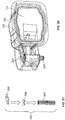
Figure 19 illustrates a perspective front exploded view of the nozzle-receivingassembly 100, according to an embodiment of the present disclosure.Figure 20 illustrates a perspective front view of the nozzle-receivingassembly 100. Referring toFigures 19 and20 , adistal end 220 of thehinge arm 128 may include apivot tube 222 that pivotally couples (such as is retained or retains) areciprocal pivot tube 224 of thehousing 102. Anadditive fill port 228 extends downwardly fromhousing 102 below the pivotal coupling of thepivot tube 222 and thepivot tube 224. Avalve insert 230 may be retained within theadditive fill port 228. -
Figure 21 illustrates a perspective front exploded view of a securingpin member 260, according to an embodiment of the present disclosure. The securingpin member 260 includes anaxle tube 262, arotatable half valve 264, and acap 266. In at least one embodiment, referring toFigures 19-21 , thevalve 264 is secured into a hollow keyed portion of theaxle tube 262. Thecap 266 is then secured over theaxle tube 262, which is sealingly secured within a central passage of thepivot tube 222 and/or thepivot tube 224. Thevalve 264 rotates in response to the pivotal motion of thehinge arm 128. When thedoor 114 is in the closed position, thevalve 264 closes a fluid passage. When thedoor 114 is in the open position, thevalve 264 provides an opening through the fluid passage. -
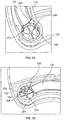
Figure 22 illustrates a top view of avalve member 275 in a closed position, according to an embodiment of the present disclosure.Figure 23 illustrates a top view of thevalve member 275 in an open position. Thevalve member 275 includes thevalve insert 230 and thevalve 264. Thevalve insert 230 is fixed in position within thefluid passage 280, which extends through the pivot axle of thehinge arm 128 and thehousing 102. Thevalve 264 rotates within thefluid passage 280 as thehinge arm 128 rotates relative to thehousing 102. Referring toFigures 19-23 , when thedoor 114 is closed, thevalve 264 and thevalve insert 230 cooperate to close the outlet of thefluid passage 280, as shown inFigure 22 . When thedoor 114 is opened, thevalve 264 and thevalve insert 230 cooperate to open the outlet of thefluid passage 280 to formfluid outlets 281, which allow additive to flow therethrough, as shown inFigure 23 . As such, thevalve member 275, which may include thevalve insert 230 and thevalve 264, operates to selectively close and open the outlet of the fluid passage. The closed position of the valve member 275 (as shown inFigure 22 ) is associated with the closed position of thedoor 114. The open position of thevalve member 275 is associated with the open position of thedoor 114. - The
valve member 275 is disposed within thefluid passage 280, such as a portion of the additive fill port. The valve member closes 275 thefluid passage 280 when thedoor 114 is in the closed position. Thevalve member 275 provides at least oneoutlet 281 in thefluid passage 280 when thedoor 114 is in the open position. - Various other valve members may be used other than shown. For example, a valve may include a flap or other such structure within the
fill passage 280 that moves between open and closed positions based on the position of thedoor 114. Optionally, the nozzle-receivingassembly 100 may not include a valve member. - Embodiments of the present disclosure may be used with capped or capless inlets. Dust flaps may be used with various embodiments.
- As described herein, certain embodiments of the present disclosure provide nozzle-receiving assemblies that are configured to receive a fuel-dispensing nozzle (such as a diesel fuel-dispensing nozzle) and a DEF-dispensing nozzle. The nozzle-receiving assemblies include a main housing and a door moveably secured to the main housing. A fuel inlet is disposed within the main housing. A DEF inlet is secured to an interior surface of the door. When the door is opened, the DEF inlet is distally located from the fuel inlet, thereby reducing a potential of DEF mixing with fuel.
- While various spatial and directional terms, such as top, bottom, lower, mid, lateral, horizontal, vertical, front and the like may be used to describe embodiments of the present disclosure, it is understood that such terms are merely used with respect to the orientations shown in the drawings. The orientations may be inverted, rotated, or otherwise changed, such that an upper portion is a lower portion, and vice versa, horizontal becomes vertical, and the like.
- Variations and modifications of the foregoing are within the scope of the present disclosure. It is understood that the embodiments disclosed and defined herein extend to all alternative combinations of two or more of the individual features mentioned or evident from the text and/or drawings. All of these different combinations constitute various alternative aspects of the present disclosure. The embodiments described herein explain the best modes known for practicing the disclosure and will enable others skilled in the art to utilize the disclosure. The claims are to be construed to include alternative embodiments to the extent permitted by the prior art.
- To the extent used in the appended claims, the terms "including" and "in which" are used as the plain-English equivalents of the respective terms "comprising" and "wherein." Moreover, to the extent used in the following claims, the terms "first," "second," and "third," etc. are used merely as labels, and are not intended to impose numerical requirements on their objects. Further, the limitations of the following claims are not written in means-plus-function format and are not intended to be interpreted based on 35 U.S.C. § 112(f), unless and until such claim limitations expressly use the phrase "means for" followed by a statement of function void of further structure.
- Various features of the disclosure are set forth in the following claims.
Claims (15)
- A nozzle-receiving assembly comprising:- a housing including a fuel inlet that is configured to receive a first nozzle of a fuel dispenser in order to dispense fuel into a fuel fill pipe coupled to the fuel inlet;- a door moveably secured to the housing, wherein the door is configured to be moved between an open position and a closed position; and- an additive inlet extending from the door, wherein the additive inlet is configured to receive a second nozzle of an additive dispenser to dispense additive into an additive conduit coupled to the additive inlet.
- The nozzle-receiving assembly of claim 1,
wherein the fuel is diesel fuel and the additive is diesel emission fluid (DEF). - The nozzle-receiving assembly of claims 1 or 2,
further comprising a hinge arm that moveably couples the door to the housing, wherein at least a portion of the additive conduit is secured to the hinge arm. - The nozzle-receiving assembly of claim 3,
wherein the additive conduit comprises at least one curved segment secured to the hinge arm. - The nozzle-receiving assembly of any of claims 1 to 4,
wherein the additive inlet extends from an interior surface of the door. - The nozzle-receiving assembly of any of claims 1 to 5,
wherein the fuel inlet and the additive inlet are covered by the door in the closed position, and wherein the fuel inlet and the additive inlet are exposed when the door is in the open position. - The nozzle-receiving assembly of any of claims 1 to 6,
wherein the fuel inlet is spaced apart from the additive inlet a first distance when the door is in the closed position, wherein the fuel inlet is spaced apart from the additive inlet a second distance when the door is in the open position, and wherein the second distance exceeds the first distance. - The nozzle-receiving assembly of any of claims 1 to 7,
further comprising a trough extending from the door, wherein the trough defines a fluid retention chamber that connects to the additive inlet. - The nozzle-receiving assembly of any of claims 1 to 8,
wherein the additive inlet comprises a moveable flap that is configured to open and close to selectively open and close the additive inlet. - The nozzle-receiving assembly of any of claims 1 to 9,
wherein the additive inlet is outwardly disposed and spaced apart from the fuel inlet when the door is in the closed position. - The nozzle-receiving assembly of any of claims 1 to 10,
further comprising a magnetic interlock ring connected to one or both of the additive inlet or the additive conduit. - The nozzle-receiving assembly of any of claims 1 to 11,
further comprising a flexible tube that extends through a portion of the housing, wherein the flexible tube connects to the additive conduit. - The nozzle-receiving assembly of any of claims 1 to 12,
wherein the additive conduit connects to an additive fill line when the door is in the open position, and wherein the additive conduit is disconnected from the additive fill line when the door is in the closed position. - The nozzle-receiving assembly of any of claims 1 to 13,
wherein the door moveably connects to the housing through a pivot axle, wherein at least a portion of an additive fill port extends through the pivot axle, and wherein the additive conduit connects to the at least a portion of the additive fill port. - The nozzle-receiving assembly of claim 14,
wherein a valve member is disposed within the additive fill port, wherein the valve member closes the additive fill port when the door is in the closed position, and wherein the valve member provides at least one outlet in the additive fill port when the door is in the open position.
Applications Claiming Priority (2)
| Application Number | Priority Date | Filing Date | Title |
|---|---|---|---|
| US201762481379P | 2017-04-04 | 2017-04-04 | |
| US15/913,984 US10543746B2 (en) | 2017-04-04 | 2018-03-07 | Dual nozzle-receiving assembly |
Publications (3)
| Publication Number | Publication Date |
|---|---|
| EP3388272A2 true EP3388272A2 (en) | 2018-10-17 |
| EP3388272A3 EP3388272A3 (en) | 2018-12-26 |
| EP3388272B1 EP3388272B1 (en) | 2020-01-29 |
Family
ID=61827590
Family Applications (1)
| Application Number | Title | Priority Date | Filing Date |
|---|---|---|---|
| EP18164220.8A Active EP3388272B1 (en) | 2017-04-04 | 2018-03-27 | Dual nozzle-receiving assembly |
Country Status (2)
| Country | Link |
|---|---|
| US (1) | US10543746B2 (en) |
| EP (1) | EP3388272B1 (en) |
Families Citing this family (1)
| Publication number | Priority date | Publication date | Assignee | Title |
|---|---|---|---|---|
| FR3146099A1 (en) * | 2023-02-27 | 2024-08-30 | Psa Automobiles Sa | MOTOR VEHICLE WITH ENERGY RECHARGING HATCH AND MECHANISM FOR OPERATING A RECHARGING END |
Citations (8)
| Publication number | Priority date | Publication date | Assignee | Title |
|---|---|---|---|---|
| FR2753138A1 (en) | 1996-09-12 | 1998-03-13 | Journee Paul Sa | Filler for motor vehicle fuel tank |
| WO2005077698A1 (en) | 2004-01-19 | 2005-08-25 | Itw Automotive Products Gmbh & Co.Kg | Filler neck to fill fuel into a vehicle tank |
| US7549443B2 (en) | 2003-12-09 | 2009-06-23 | Illinois Tool Works Inc. | Fuel shut-off valve assembly with associated components and methods of making and assembling the same |
| WO2010021829A1 (en) | 2008-08-20 | 2010-02-25 | Illinois Tool Works Inc. | Mis-fuel inhibitor |
| WO2011053563A1 (en) | 2009-10-30 | 2011-05-05 | Illinois Tool Works Inc. | Capless refueling system |
| US8100155B2 (en) | 2006-09-13 | 2012-01-24 | I.T.W. De France | End piece for the filling of a tank |
| US8714214B2 (en) | 2009-03-12 | 2014-05-06 | Illinois Tool Works | Mis-fuel inhibitor |
| US8910678B2 (en) | 2007-04-16 | 2014-12-16 | Illinois Tool Works Inc. | Selective fuel nozzle inhibiting system |
Family Cites Families (6)
| Publication number | Priority date | Publication date | Assignee | Title |
|---|---|---|---|---|
| US5431199A (en) * | 1993-11-30 | 1995-07-11 | Benjey, Robert P | Redundant seal for vehicle filler neck |
| FR2875748B1 (en) * | 2004-09-27 | 2006-12-08 | Inergy Automotive Systems Res | METHOD FOR FILLING A RESERVOIR USING AN ASSOCIATED CARTRIDGE-RESERVOIR AND CARTRIDGE |
| JP2007153049A (en) * | 2005-12-02 | 2007-06-21 | Toyoda Gosei Co Ltd | Opening and closing device for tank |
| JP5666330B2 (en) * | 2011-02-07 | 2015-02-12 | 株式会社ニフコ | Oil filler opening and closing device |
| FR3012773B1 (en) | 2013-11-07 | 2016-02-05 | Renault Sas | FUEL FILLING DEVICE OF A FUEL TANK FOR A MOTOR VEHICLE AND SYSTEM THEREOF |
| DE202014005799U1 (en) * | 2014-07-16 | 2015-10-20 | GM Global Technology Operations, LLC (n.d. Ges. d. Staates Delaware) | Motor vehicle tank flap arrangement |
-
2018
- 2018-03-07 US US15/913,984 patent/US10543746B2/en not_active Expired - Fee Related
- 2018-03-27 EP EP18164220.8A patent/EP3388272B1/en active Active
Patent Citations (9)
| Publication number | Priority date | Publication date | Assignee | Title |
|---|---|---|---|---|
| FR2753138A1 (en) | 1996-09-12 | 1998-03-13 | Journee Paul Sa | Filler for motor vehicle fuel tank |
| US7549443B2 (en) | 2003-12-09 | 2009-06-23 | Illinois Tool Works Inc. | Fuel shut-off valve assembly with associated components and methods of making and assembling the same |
| WO2005077698A1 (en) | 2004-01-19 | 2005-08-25 | Itw Automotive Products Gmbh & Co.Kg | Filler neck to fill fuel into a vehicle tank |
| US7950425B2 (en) | 2004-01-19 | 2011-05-31 | Itw Automotive Products Gmbh & Co Kg | Filler neck to fill fuel into a vehicle tank |
| US8100155B2 (en) | 2006-09-13 | 2012-01-24 | I.T.W. De France | End piece for the filling of a tank |
| US8910678B2 (en) | 2007-04-16 | 2014-12-16 | Illinois Tool Works Inc. | Selective fuel nozzle inhibiting system |
| WO2010021829A1 (en) | 2008-08-20 | 2010-02-25 | Illinois Tool Works Inc. | Mis-fuel inhibitor |
| US8714214B2 (en) | 2009-03-12 | 2014-05-06 | Illinois Tool Works | Mis-fuel inhibitor |
| WO2011053563A1 (en) | 2009-10-30 | 2011-05-05 | Illinois Tool Works Inc. | Capless refueling system |
Also Published As
| Publication number | Publication date |
|---|---|
| EP3388272B1 (en) | 2020-01-29 |
| US10543746B2 (en) | 2020-01-28 |
| US20180281588A1 (en) | 2018-10-04 |
| EP3388272A3 (en) | 2018-12-26 |
Similar Documents
| Publication | Publication Date | Title |
|---|---|---|
| US6390147B1 (en) | Fuel and reductant delivery system | |
| US9957152B2 (en) | Dual-fluid dispensing system and apparatus for diesel vehicle | |
| JP2626729B2 (en) | Connection tubing for fuel tank filling | |
| US9272618B2 (en) | Misfuelling prevention device for a filler neck of a fuel tank | |
| US10926997B2 (en) | Co-fueling nozzle with dual spouts | |
| US9744849B2 (en) | Fuel nozzle receiving assembly | |
| US10640358B2 (en) | Capless refill adapter for a fluid refilling system | |
| WO2014133813A1 (en) | Improper fuel nozzle insertion-inhibiting assembly | |
| EP3081801B1 (en) | Flap valve device and gas-liquid separating device comprising flap valve device | |
| US10207579B2 (en) | Fuel-mixing prevention filler neck device | |
| US20180038320A1 (en) | Multi-stage check valve for vapor recirculation line of liquid containment system | |
| EP3388272B1 (en) | Dual nozzle-receiving assembly | |
| US10059198B2 (en) | Improper fuel nozzle insertion-inhibiting assembly | |
| US9499046B2 (en) | Spill-preventing fuel intake assembly | |
| US6938612B2 (en) | Auxiliary fuel dispensing system | |
| US9522594B2 (en) | Improper fuel nozzle insertion-inhibiting system | |
| US11325462B2 (en) | Capless closure assembly for fuel-tank filler pipe | |
| US20210031619A1 (en) | Filler neck for filling an operating substance or additive into a vehicle tank by means of a fuel pump nozzle | |
| EP1660342A1 (en) | Replacement vehicle fuel intake device | |
| EP1581405A2 (en) | Vehicle fuel intake device |
Legal Events
| Date | Code | Title | Description |
|---|---|---|---|
| PUAI | Public reference made under article 153(3) epc to a published international application that has entered the european phase |
Free format text: ORIGINAL CODE: 0009012 |
|
| STAA | Information on the status of an ep patent application or granted ep patent |
Free format text: STATUS: REQUEST FOR EXAMINATION WAS MADE |
|
| 17P | Request for examination filed |
Effective date: 20180327 |
|
| AK | Designated contracting states |
Kind code of ref document: A2 Designated state(s): AL AT BE BG CH CY CZ DE DK EE ES FI FR GB GR HR HU IE IS IT LI LT LU LV MC MK MT NL NO PL PT RO RS SE SI SK SM TR |
|
| AX | Request for extension of the european patent |
Extension state: BA ME |
|
| PUAL | Search report despatched |
Free format text: ORIGINAL CODE: 0009013 |
|
| AK | Designated contracting states |
Kind code of ref document: A3 Designated state(s): AL AT BE BG CH CY CZ DE DK EE ES FI FR GB GR HR HU IE IS IT LI LT LU LV MC MK MT NL NO PL PT RO RS SE SI SK SM TR |
|
| AX | Request for extension of the european patent |
Extension state: BA ME |
|
| RIC1 | Information provided on ipc code assigned before grant |
Ipc: B60K 15/04 20060101AFI20181116BHEP Ipc: B60K 15/05 20060101ALI20181116BHEP |
|
| GRAP | Despatch of communication of intention to grant a patent |
Free format text: ORIGINAL CODE: EPIDOSNIGR1 |
|
| STAA | Information on the status of an ep patent application or granted ep patent |
Free format text: STATUS: GRANT OF PATENT IS INTENDED |
|
| INTG | Intention to grant announced |
Effective date: 20190828 |
|
| GRAS | Grant fee paid |
Free format text: ORIGINAL CODE: EPIDOSNIGR3 |
|
| GRAA | (expected) grant |
Free format text: ORIGINAL CODE: 0009210 |
|
| STAA | Information on the status of an ep patent application or granted ep patent |
Free format text: STATUS: THE PATENT HAS BEEN GRANTED |
|
| AK | Designated contracting states |
Kind code of ref document: B1 Designated state(s): AL AT BE BG CH CY CZ DE DK EE ES FI FR GB GR HR HU IE IS IT LI LT LU LV MC MK MT NL NO PL PT RO RS SE SI SK SM TR |
|
| REG | Reference to a national code |
Ref country code: GB Ref legal event code: FG4D |
|
| REG | Reference to a national code |
Ref country code: CH Ref legal event code: EP |
|
| REG | Reference to a national code |
Ref country code: AT Ref legal event code: REF Ref document number: 1228261 Country of ref document: AT Kind code of ref document: T Effective date: 20200215 |
|
| REG | Reference to a national code |
Ref country code: IE Ref legal event code: FG4D |
|
| REG | Reference to a national code |
Ref country code: DE Ref legal event code: R096 Ref document number: 602018002175 Country of ref document: DE |
|
| REG | Reference to a national code |
Ref country code: NL Ref legal event code: MP Effective date: 20200129 |
|
| PG25 | Lapsed in a contracting state [announced via postgrant information from national office to epo] |
Ref country code: RS Free format text: LAPSE BECAUSE OF FAILURE TO SUBMIT A TRANSLATION OF THE DESCRIPTION OR TO PAY THE FEE WITHIN THE PRESCRIBED TIME-LIMIT Effective date: 20200129 Ref country code: FI Free format text: LAPSE BECAUSE OF FAILURE TO SUBMIT A TRANSLATION OF THE DESCRIPTION OR TO PAY THE FEE WITHIN THE PRESCRIBED TIME-LIMIT Effective date: 20200129 Ref country code: PT Free format text: LAPSE BECAUSE OF FAILURE TO SUBMIT A TRANSLATION OF THE DESCRIPTION OR TO PAY THE FEE WITHIN THE PRESCRIBED TIME-LIMIT Effective date: 20200621 Ref country code: NO Free format text: LAPSE BECAUSE OF FAILURE TO SUBMIT A TRANSLATION OF THE DESCRIPTION OR TO PAY THE FEE WITHIN THE PRESCRIBED TIME-LIMIT Effective date: 20200429 |
|
| REG | Reference to a national code |
Ref country code: LT Ref legal event code: MG4D |
|
| PG25 | Lapsed in a contracting state [announced via postgrant information from national office to epo] |
Ref country code: GR Free format text: LAPSE BECAUSE OF FAILURE TO SUBMIT A TRANSLATION OF THE DESCRIPTION OR TO PAY THE FEE WITHIN THE PRESCRIBED TIME-LIMIT Effective date: 20200430 Ref country code: BG Free format text: LAPSE BECAUSE OF FAILURE TO SUBMIT A TRANSLATION OF THE DESCRIPTION OR TO PAY THE FEE WITHIN THE PRESCRIBED TIME-LIMIT Effective date: 20200429 Ref country code: HR Free format text: LAPSE BECAUSE OF FAILURE TO SUBMIT A TRANSLATION OF THE DESCRIPTION OR TO PAY THE FEE WITHIN THE PRESCRIBED TIME-LIMIT Effective date: 20200129 Ref country code: IS Free format text: LAPSE BECAUSE OF FAILURE TO SUBMIT A TRANSLATION OF THE DESCRIPTION OR TO PAY THE FEE WITHIN THE PRESCRIBED TIME-LIMIT Effective date: 20200529 Ref country code: SE Free format text: LAPSE BECAUSE OF FAILURE TO SUBMIT A TRANSLATION OF THE DESCRIPTION OR TO PAY THE FEE WITHIN THE PRESCRIBED TIME-LIMIT Effective date: 20200129 Ref country code: LV Free format text: LAPSE BECAUSE OF FAILURE TO SUBMIT A TRANSLATION OF THE DESCRIPTION OR TO PAY THE FEE WITHIN THE PRESCRIBED TIME-LIMIT Effective date: 20200129 |
|
| PG25 | Lapsed in a contracting state [announced via postgrant information from national office to epo] |
Ref country code: NL Free format text: LAPSE BECAUSE OF FAILURE TO SUBMIT A TRANSLATION OF THE DESCRIPTION OR TO PAY THE FEE WITHIN THE PRESCRIBED TIME-LIMIT Effective date: 20200129 |
|
| PG25 | Lapsed in a contracting state [announced via postgrant information from national office to epo] |
Ref country code: SM Free format text: LAPSE BECAUSE OF FAILURE TO SUBMIT A TRANSLATION OF THE DESCRIPTION OR TO PAY THE FEE WITHIN THE PRESCRIBED TIME-LIMIT Effective date: 20200129 Ref country code: LT Free format text: LAPSE BECAUSE OF FAILURE TO SUBMIT A TRANSLATION OF THE DESCRIPTION OR TO PAY THE FEE WITHIN THE PRESCRIBED TIME-LIMIT Effective date: 20200129 Ref country code: SK Free format text: LAPSE BECAUSE OF FAILURE TO SUBMIT A TRANSLATION OF THE DESCRIPTION OR TO PAY THE FEE WITHIN THE PRESCRIBED TIME-LIMIT Effective date: 20200129 Ref country code: RO Free format text: LAPSE BECAUSE OF FAILURE TO SUBMIT A TRANSLATION OF THE DESCRIPTION OR TO PAY THE FEE WITHIN THE PRESCRIBED TIME-LIMIT Effective date: 20200129 Ref country code: DK Free format text: LAPSE BECAUSE OF FAILURE TO SUBMIT A TRANSLATION OF THE DESCRIPTION OR TO PAY THE FEE WITHIN THE PRESCRIBED TIME-LIMIT Effective date: 20200129 Ref country code: EE Free format text: LAPSE BECAUSE OF FAILURE TO SUBMIT A TRANSLATION OF THE DESCRIPTION OR TO PAY THE FEE WITHIN THE PRESCRIBED TIME-LIMIT Effective date: 20200129 Ref country code: MC Free format text: LAPSE BECAUSE OF FAILURE TO SUBMIT A TRANSLATION OF THE DESCRIPTION OR TO PAY THE FEE WITHIN THE PRESCRIBED TIME-LIMIT Effective date: 20200129 Ref country code: ES Free format text: LAPSE BECAUSE OF FAILURE TO SUBMIT A TRANSLATION OF THE DESCRIPTION OR TO PAY THE FEE WITHIN THE PRESCRIBED TIME-LIMIT Effective date: 20200129 Ref country code: CZ Free format text: LAPSE BECAUSE OF FAILURE TO SUBMIT A TRANSLATION OF THE DESCRIPTION OR TO PAY THE FEE WITHIN THE PRESCRIBED TIME-LIMIT Effective date: 20200129 |
|
| REG | Reference to a national code |
Ref country code: DE Ref legal event code: R097 Ref document number: 602018002175 Country of ref document: DE |
|
| REG | Reference to a national code |
Ref country code: AT Ref legal event code: MK05 Ref document number: 1228261 Country of ref document: AT Kind code of ref document: T Effective date: 20200129 |
|
| PLBE | No opposition filed within time limit |
Free format text: ORIGINAL CODE: 0009261 |
|
| STAA | Information on the status of an ep patent application or granted ep patent |
Free format text: STATUS: NO OPPOSITION FILED WITHIN TIME LIMIT |
|
| REG | Reference to a national code |
Ref country code: BE Ref legal event code: MM Effective date: 20200331 |
|
| PG25 | Lapsed in a contracting state [announced via postgrant information from national office to epo] |
Ref country code: LU Free format text: LAPSE BECAUSE OF NON-PAYMENT OF DUE FEES Effective date: 20200327 |
|
| 26N | No opposition filed |
Effective date: 20201030 |
|
| PG25 | Lapsed in a contracting state [announced via postgrant information from national office to epo] |
Ref country code: IT Free format text: LAPSE BECAUSE OF FAILURE TO SUBMIT A TRANSLATION OF THE DESCRIPTION OR TO PAY THE FEE WITHIN THE PRESCRIBED TIME-LIMIT Effective date: 20200129 Ref country code: AT Free format text: LAPSE BECAUSE OF FAILURE TO SUBMIT A TRANSLATION OF THE DESCRIPTION OR TO PAY THE FEE WITHIN THE PRESCRIBED TIME-LIMIT Effective date: 20200129 Ref country code: FR Free format text: LAPSE BECAUSE OF NON-PAYMENT OF DUE FEES Effective date: 20200329 Ref country code: IE Free format text: LAPSE BECAUSE OF NON-PAYMENT OF DUE FEES Effective date: 20200327 |
|
| PG25 | Lapsed in a contracting state [announced via postgrant information from national office to epo] |
Ref country code: SI Free format text: LAPSE BECAUSE OF FAILURE TO SUBMIT A TRANSLATION OF THE DESCRIPTION OR TO PAY THE FEE WITHIN THE PRESCRIBED TIME-LIMIT Effective date: 20200129 Ref country code: PL Free format text: LAPSE BECAUSE OF FAILURE TO SUBMIT A TRANSLATION OF THE DESCRIPTION OR TO PAY THE FEE WITHIN THE PRESCRIBED TIME-LIMIT Effective date: 20200129 Ref country code: BE Free format text: LAPSE BECAUSE OF NON-PAYMENT OF DUE FEES Effective date: 20200331 |
|
| REG | Reference to a national code |
Ref country code: CH Ref legal event code: PL |
|
| PG25 | Lapsed in a contracting state [announced via postgrant information from national office to epo] |
Ref country code: LI Free format text: LAPSE BECAUSE OF NON-PAYMENT OF DUE FEES Effective date: 20210331 Ref country code: CH Free format text: LAPSE BECAUSE OF NON-PAYMENT OF DUE FEES Effective date: 20210331 |
|
| PGFP | Annual fee paid to national office [announced via postgrant information from national office to epo] |
Ref country code: DE Payment date: 20220329 Year of fee payment: 5 |
|
| PG25 | Lapsed in a contracting state [announced via postgrant information from national office to epo] |
Ref country code: TR Free format text: LAPSE BECAUSE OF FAILURE TO SUBMIT A TRANSLATION OF THE DESCRIPTION OR TO PAY THE FEE WITHIN THE PRESCRIBED TIME-LIMIT Effective date: 20200129 Ref country code: MT Free format text: LAPSE BECAUSE OF FAILURE TO SUBMIT A TRANSLATION OF THE DESCRIPTION OR TO PAY THE FEE WITHIN THE PRESCRIBED TIME-LIMIT Effective date: 20200129 Ref country code: CY Free format text: LAPSE BECAUSE OF FAILURE TO SUBMIT A TRANSLATION OF THE DESCRIPTION OR TO PAY THE FEE WITHIN THE PRESCRIBED TIME-LIMIT Effective date: 20200129 |
|
| PG25 | Lapsed in a contracting state [announced via postgrant information from national office to epo] |
Ref country code: MK Free format text: LAPSE BECAUSE OF FAILURE TO SUBMIT A TRANSLATION OF THE DESCRIPTION OR TO PAY THE FEE WITHIN THE PRESCRIBED TIME-LIMIT Effective date: 20200129 Ref country code: AL Free format text: LAPSE BECAUSE OF FAILURE TO SUBMIT A TRANSLATION OF THE DESCRIPTION OR TO PAY THE FEE WITHIN THE PRESCRIBED TIME-LIMIT Effective date: 20200129 |
|
| GBPC | Gb: european patent ceased through non-payment of renewal fee |
Effective date: 20220327 |
|
| PG25 | Lapsed in a contracting state [announced via postgrant information from national office to epo] |
Ref country code: GB Free format text: LAPSE BECAUSE OF NON-PAYMENT OF DUE FEES Effective date: 20220327 |
|
| REG | Reference to a national code |
Ref country code: DE Ref legal event code: R119 Ref document number: 602018002175 Country of ref document: DE |
|
| PG25 | Lapsed in a contracting state [announced via postgrant information from national office to epo] |
Ref country code: DE Free format text: LAPSE BECAUSE OF NON-PAYMENT OF DUE FEES Effective date: 20231003 |