EP3388270A1 - Connecting structure between a cowl louver and a windshield - Google Patents
Connecting structure between a cowl louver and a windshield Download PDFInfo
- Publication number
- EP3388270A1 EP3388270A1 EP18000302.2A EP18000302A EP3388270A1 EP 3388270 A1 EP3388270 A1 EP 3388270A1 EP 18000302 A EP18000302 A EP 18000302A EP 3388270 A1 EP3388270 A1 EP 3388270A1
- Authority
- EP
- European Patent Office
- Prior art keywords
- glass plate
- windshield
- spacer
- connecting structure
- disposed
- Prior art date
- Legal status (The legal status is an assumption and is not a legal conclusion. Google has not performed a legal analysis and makes no representation as to the accuracy of the status listed.)
- Granted
Links
Images


Classifications
-
- B—PERFORMING OPERATIONS; TRANSPORTING
- B60—VEHICLES IN GENERAL
- B60J—WINDOWS, WINDSCREENS, NON-FIXED ROOFS, DOORS, OR SIMILAR DEVICES FOR VEHICLES; REMOVABLE EXTERNAL PROTECTIVE COVERINGS SPECIALLY ADAPTED FOR VEHICLES
- B60J10/00—Sealing arrangements
- B60J10/70—Sealing arrangements specially adapted for windows or windscreens
-
- B—PERFORMING OPERATIONS; TRANSPORTING
- B60—VEHICLES IN GENERAL
- B60J—WINDOWS, WINDSCREENS, NON-FIXED ROOFS, DOORS, OR SIMILAR DEVICES FOR VEHICLES; REMOVABLE EXTERNAL PROTECTIVE COVERINGS SPECIALLY ADAPTED FOR VEHICLES
- B60J1/00—Windows; Windscreens; Accessories therefor
- B60J1/02—Windows; Windscreens; Accessories therefor arranged at the vehicle front, e.g. structure of the glazing, mounting of the glazing
-
- B—PERFORMING OPERATIONS; TRANSPORTING
- B60—VEHICLES IN GENERAL
- B60J—WINDOWS, WINDSCREENS, NON-FIXED ROOFS, DOORS, OR SIMILAR DEVICES FOR VEHICLES; REMOVABLE EXTERNAL PROTECTIVE COVERINGS SPECIALLY ADAPTED FOR VEHICLES
- B60J10/00—Sealing arrangements
- B60J10/30—Sealing arrangements characterised by the fastening means
- B60J10/32—Sealing arrangements characterised by the fastening means using integral U-shaped retainers
- B60J10/33—Sealing arrangements characterised by the fastening means using integral U-shaped retainers characterised by the configuration of the retaining lips
-
- B—PERFORMING OPERATIONS; TRANSPORTING
- B62—LAND VEHICLES FOR TRAVELLING OTHERWISE THAN ON RAILS
- B62D—MOTOR VEHICLES; TRAILERS
- B62D25/00—Superstructure or monocoque structure sub-units; Parts or details thereof not otherwise provided for
- B62D25/08—Front or rear portions
- B62D25/081—Cowls
-
- B—PERFORMING OPERATIONS; TRANSPORTING
- B62—LAND VEHICLES FOR TRAVELLING OTHERWISE THAN ON RAILS
- B62D—MOTOR VEHICLES; TRAILERS
- B62D25/00—Superstructure or monocoque structure sub-units; Parts or details thereof not otherwise provided for
- B62D25/08—Front or rear portions
- B62D25/10—Bonnets or lids, e.g. for trucks, tractors, busses, work vehicles
- B62D25/12—Parts or details thereof
-
- H—ELECTRICITY
- H05—ELECTRIC TECHNIQUES NOT OTHERWISE PROVIDED FOR
- H05B—ELECTRIC HEATING; ELECTRIC LIGHT SOURCES NOT OTHERWISE PROVIDED FOR; CIRCUIT ARRANGEMENTS FOR ELECTRIC LIGHT SOURCES, IN GENERAL
- H05B3/00—Ohmic-resistance heating
- H05B3/84—Heating arrangements specially adapted for transparent or reflecting areas, e.g. for demisting or de-icing windows, mirrors or vehicle windshields
- H05B3/86—Heating arrangements specially adapted for transparent or reflecting areas, e.g. for demisting or de-icing windows, mirrors or vehicle windshields the heating conductors being embedded in the transparent or reflecting material
-
- B—PERFORMING OPERATIONS; TRANSPORTING
- B60—VEHICLES IN GENERAL
- B60R—VEHICLES, VEHICLE FITTINGS, OR VEHICLE PARTS, NOT OTHERWISE PROVIDED FOR
- B60R16/00—Electric or fluid circuits specially adapted for vehicles and not otherwise provided for; Arrangement of elements of electric or fluid circuits specially adapted for vehicles and not otherwise provided for
- B60R16/02—Electric or fluid circuits specially adapted for vehicles and not otherwise provided for; Arrangement of elements of electric or fluid circuits specially adapted for vehicles and not otherwise provided for electric constitutive elements
- B60R16/03—Electric or fluid circuits specially adapted for vehicles and not otherwise provided for; Arrangement of elements of electric or fluid circuits specially adapted for vehicles and not otherwise provided for electric constitutive elements for supply of electrical power to vehicle subsystems or for
-
- H—ELECTRICITY
- H05—ELECTRIC TECHNIQUES NOT OTHERWISE PROVIDED FOR
- H05B—ELECTRIC HEATING; ELECTRIC LIGHT SOURCES NOT OTHERWISE PROVIDED FOR; CIRCUIT ARRANGEMENTS FOR ELECTRIC LIGHT SOURCES, IN GENERAL
- H05B2203/00—Aspects relating to Ohmic resistive heating covered by group H05B3/00
- H05B2203/013—Heaters using resistive films or coatings
-
- H—ELECTRICITY
- H05—ELECTRIC TECHNIQUES NOT OTHERWISE PROVIDED FOR
- H05B—ELECTRIC HEATING; ELECTRIC LIGHT SOURCES NOT OTHERWISE PROVIDED FOR; CIRCUIT ARRANGEMENTS FOR ELECTRIC LIGHT SOURCES, IN GENERAL
- H05B2203/00—Aspects relating to Ohmic resistive heating covered by group H05B3/00
- H05B2203/016—Heaters using particular connecting means
Definitions
- the present invention relates to a connecting structure between a cowl louver and a windshield.
- a cowl louver has a clamping portion disposed on the rear end portion, and that the clamping portion includes a clamping edge portion and a plurality of clamping members disposed at certain intervals to clamp the lower edge portion of the windshield.
- a windshield have a deicer or the like disposed therein to melt frost, snow, ice or the like adhering to the windshield.
- an interior side glass plate of two glass plates forming the windshield has a cutout portion partly formed therein, and the exterior side glass plate has a power feed portion disposed on an interior side surface.
- the power feed portion is electrically connected to a power source disposed outside of the windshield by conductors.
- the cutout portion has a sealant filled therein.
- the cowl louver When the sealant in the cutout portion has a greater thickness than the interior side glass plate, it is possible to more reliably protect a connection portion between the power feed portion and the conductors from entry of external moisture. In this case, the cowl louver could, however, fail to clamp the lower edge portion of a windshield by the clamping portion. In order to avoid this problem, the cowl louver needs to have the clamping portion disposed so as to avoid the cutout portion of the windshield. This leads to a decrease in the degree of freedom in design and a reduction in versatility with respect to cowl louvers.
- a connecting structure between a cowl louver and a windshield such that the cowl louver has a rear end portion connected to a lower edge portion of the windshield
- the connecting structure including a windshield including a laminated glass having a first glass plate disposed on an exterior side, a second glass plate disposed on an interior side and an interlayer bonding the first glass plate and the second glass plate; the laminated glass having a cutout portion formed by removing a part of the second glass plate and the interlayer at a certain area of a lower edge portion of the laminated glass; the first glass having a power feed portion disposed on an interior side surface thereof in the cutout portion;; and a spacer disposed in the cutout portion on a lower edge side of the windshield closer than the power feed portion; and the cowl louver including a clamping portion formed in a U-character shape in section at a rear end portion thereof, the clamping portion having an upper member disposed along the first glass plate and a lower member disposed so as to be
- the connecting structure between a cowl louver and a windshield according to the present invention is capable of improving the degree of freedom in design and the versatility with respect to cowl louvers because the clamping portion of the cowl louver clamps the first glass plate and the spacer disposed in the cutout portion.
- Fig. 1 is a view showing a windshield 10 and a cowl louver 60 which are seen from an interior side.
- the cowl louver 60 has a rear end portion connected to a lower edge portion of the windshield 10.
- the windshield 10 includes a laminated glass 12; a cutout portion 26; electrodes 28, terminals 32 and a spacer 40 which are disposed in the cutout portion 26; and heating wires 22 for heating a lateral side portion and a lower side portion of the laminated glass.
- heating wires 22 There is no particular limitation to the area where the heating wires 22 are disposed.
- the laminated glass 12 is a laminated glass which includes a first glass plate disposed on an exterior side, a second glass plate disposed on an interior side, both glass plates being bonded through an interlayer.
- the cowl louver 60 includes a clamping portion 62 at the rear end portion, which is defined by an upper member 64 disposed so as to extend along the first glass plate, and a plurality of lower members 66 disposed on a certain area of the cowl louver close to the second glass plate, and which is formed in a U-character shape in section.
- the clamping portion 62 clamps the windshield 10 by inserting the lower edge portion of the windshield 10 into openings defined by the upper member 64 and the lower members 66.
- the clamping portion 62 connects the windshield 10 and the cowl louver 60.
- the windshield 10 includes the laminated glass 14 which has the first glass plate 14 disposed on the exterior side, the second glass plate 16 disposed on the interior side, and the interlayer 18 bonding the first glass plate 14 and the second glass plate 16.
- the first glass plate 14 has an interior side surface 14A
- the second glass plate 16 has an exterior side surface 16A such that the interior and exterior side surfaces are bonded together by the interlayer 18.
- the interlayer 18 may be an interlayer made of PVB (Polyvinyl butyral) or an interlayer made of EVA (Ethylene-Vinyl Acetate).
- the heating wires 22 are disposed on the interior side surface 14A of the first glass plate 14.
- the heating wires 22 are made by a conductive material, such as metal.
- the metal may be, for example, gold, silver, nickel, copper, aluminum, tin, cobalt, or an allow containing at least one of these elements.
- the heating wires 22 may be formed by baking conductive paste, such as metal paste.
- the windshield 10 has the cutout portion 26 formed in a certain area of the lower edge portion.
- the cutout portion 26 is an area where a portion of the interior side surface 14A of the first glass plate 14 is exposed by removing a portion of the second glass plate 16 and a portion of the interlayer 18.
- the electrodes 28 may be formed by a similar process to the heating wires 22.
- the cutout portion 26 is formed in a substantially semi-circular shape such that the cutout portion has a length gradually increasing to a front end portion of the windshield. There is no particular limitation to the size or shape of the cutout portion 26 as long as the cutout portion is large enough to dispose the electrodes 28 in a required number.
- the cutout portion 26 has the spacer 40 disposed therein on a position closer to the lower edge portion of the windshield than the electrodes 28. As shown in Fig. 2 , the spacer is formed in a substantially cubic shape.
- the spacer 40 When the spacer 40 is disposed in the cutout portion 26, the spacer 40 functions as if the removed portion of the second glass plate 16 and the removed portion of the interlayer 18 are present. As described later, the lower edge portion of the windshield 10 can be clamped by the clamping portion 62 of the cowl louver 60 as in a certain area where the second glass plate 16 and the interlayer 18 are present.
- the spacer 40 has a width W in a direction orthogonal to a front and rear direction of the windshield, which is preferably determined to be a length such that the spacer 40 has both end portions brought into contact with the second glass plate 16 and the interlayer 18.
- the clamping portion 62 clamps the lower edge portion of the windshield 10 at the rear end portion of the cowl louver 60.
- the upper member 64 is brought into contact with an exterior side surface 14B of the first glass plate 14 while the lower members 66 are brought into contact with an interior side surface 16B of the second glass plate 16.
- the clamping portion 62 which includes the upper member 64 and the lower members 66, pinches the lower edge portion of the windshield 10.
- first glass plate 14 and the second glass plate 16 have a front end portion 14C and a front end portion 16C formed in a curved shape (chamfered), respectively.
- the electrodes 28 are disposed on the interior side surface 14A of the first glass plate 14 in the cutout portion 26.
- the electrodes 28 are electrically connected to the heating wires 22.
- the conductors 30 are connected to the electrodes 28 through the terminals 32.
- the terminals 32 are connected to the electrodes 28 by soldering.
- the upper member 64 is brought into contact with the exterior side surface 14B of the first glass plate 14 while the lower members 66 are brought into contact with the spacer 40 at its top surface portion 40A. Since the spacer functions as if the removed portion of the second glass plate 16 and the removed portion of the interlayer 18 are present, the clamping portion 62 can clamp, at the lower edge portion of the cowl louver 60, a certain area of the windshield 10 where the cutout portion 26 is formed in the lower edge portion.
- the spacer 40 has a height H reaching the top surface portion 40A, which is equal to a height H1 of the second glass plate 16 reaching the interior side surface 16B on the basis of the interior side surface 14A of the first glass plate. From this point of view, the top surface portion 40A of the spacer and the interior side surface 16B of the second glass plate 16 at the lower edge portion of the windshield 10 are preferred to be substantially flush with each other (form a substantially common plane).
- the spacer 40 and the first glass plate 14 may be bonded together by e.g. a double-sided adhesive tape 42.
- a double-sided adhesive tape 42 There is no particular limitation to the bonding method as long as the spacer 40 and the first glass plate 14 can be bonded together with the top surface portion 40A of the spacer 40 and the interior side surface 16B of the second glass plate 16 having a substantially common plane each other.
- a front end portion 40B of the spacer 40 and a front end portion 14C of the first glass plate 14 are flush with each other.
- the word “flush with” means “apparently flush with”, “completely flush with” or “substantially flush with”.
- the spacer 40 can protect the front end portion 14C of the first glass plate 14 to prevent the first glass plate 14 from being cracked or chipped. Further, it is easy to insert the lower edge portion of the windshield 10 into the clamping portion 62.
- the shape on the interior side of the front end portion 40B of the spacer 40 is the same shape as the shape on the interior side of the front end portion 16C of the second glass plate 16 (see Fig. 3 ).
- the interior side surfaces of both front end portions are formed in the same shape, it is possible to reliably insert the windshield 10 into the clamping portion 62 at any position of the lower edge portion of the windshield 10.
- the wording "the same shape” means “exactly the same shape” or “substantially the same shape”.
- the front end portion 40B of the spacer 40 is preferably formed in a curved shape as in the front end portion 16C of the second glass plate 16. Thus, it is easy to insert the windshield 10 into the clamping portion 62.
- the spacer 40 has a depth D in the front and rear direction such that the spacer is clamped by tip portions of the lower members 66 of the clamping portion 62.
- the front end portion 14C of the first glass plate 14 is preferably flush with the front end portion 40B of the space 40, the former may fail to be flush with the latter.
- the spacer 40 is preferably made of a material selected from a group comprising of a synthetic resin, metal, glass and rubber.
- the synthetic resin is preferred to be a TPE (thermoplastic elastomer) resin.
- TPE thermoplastic elastomer
- the TPE resin has a shore hardness of preferably at least Hs70.
- the spacer 40 may, however, be made of a different material or have a different shore hardness.
- a sealant 34 is filled between the spacer 40 and a combination of the second glass plate 16 and the interlayer 18 in the cutout portion 26.
- the sealant 34 may be, for example, a silicone resin.
- the sealant 34 seals and protects a portion of each conductor 30, the electrodes 28 and the terminals 32.
- the cutout portion 26 of the windshield 10 is inserted into the openings defined by the upper member 64 and the lower members 66, the upper member 64 is brought into contact with the exterior side surface 14B of the first glass plate 14 while the lower members 66 are brought into contact with the top surface portion 40A flush with the interior side surface 16B of the second glass plate.
- the clamping portion 62 clamps the first glass plate 14 and the spacer 40.
- the second glass plate 16 has a dam 50 disposed on the interior side surface 16B around the cutout portion 26.
- the spacer 40 is formed in an L-character shape as seen in section such that the spacer has a protruding portion 40C protruding toward the interior side in comparison with the top surface portion 40A at a portion that is not clamped by the lower members 66.
- the modification of the first embodiment allows the sealant 34 to be filled in a greater amount in comparison with the first embodiment.
- the sealant 34 is filled in a greater amount, it is possible to more reliably protect the relevant portion of each conductor 30, the electrodes 28 and the terminals 32. Further, it is possible to lead out the conductors 30 beyond the protruding portion 40C because of the presence of the L-character shape of spacer 40.
- the spacer 40 prevents the clamping portion 62 from nipping a conductors 30.
- the spacer 40 may be, for example, formed in a T-character shape.
- a cowl louver 60 has a rear end portion connected to a lower edge portion of a windshield 10.
- the windshield 10 includes a laminated glass 12; a cutout portion 26; electrodes 28, terminals 32 and a spacer 40 which are disposed in the cutout portion 26; and heating wires 22 for heating a lateral side portion and a lower side portion of the laminated glass.
- the windshield 10 with the cowl louver according to the second embodiment is different from the connecting structure between the cowl louver 60 and the windshield 10 according to the first embodiment in that the cowl louver 60 of the former has a clamping portion formed with a lower member 66 formed in a different shape from that of the first embodiment.
- the cowl louver 60 includes the clamping portion 62 formed in a U-character shape in section at the rear end portion, which is defined by an upper member 64 disposed so as to extend along a first glass plate 14, and the lower member 66 disposed so as to extend along a second glass plate 16.
- the lower member 66 is formed so as to continuously extend in the width direction of the cowl louver 60.
- the entire clamping portion 62 clamps the lower edge portion of the windshield 10 (a certain area of the lower edge portion where the cutout portion 26 is formed, and a certain area of the lower edge portion where the cutout portion 26 is not formed). Since the lower member 66 is formed so as to have a continuous length, it is possible to more effectively prevent moisture from entering the interior side.
Landscapes
- Engineering & Computer Science (AREA)
- Mechanical Engineering (AREA)
- Chemical & Material Sciences (AREA)
- Combustion & Propulsion (AREA)
- Transportation (AREA)
- Body Structure For Vehicles (AREA)
- Joining Of Glass To Other Materials (AREA)
Abstract
Description
- The present invention relates to a connecting structure between a cowl louver and a windshield.
- With respect to a vehicle, there has been known a structure for connecting a rear end portion of a cowl louver and a lower edge portion of a windshield (see JP-A-H5-097061).
- This Japanese publication discloses that a cowl louver has a clamping portion disposed on the rear end portion, and that the clamping portion includes a clamping edge portion and a plurality of clamping members disposed at certain intervals to clamp the lower edge portion of the windshield.
- In some cases, a windshield have a deicer or the like disposed therein to melt frost, snow, ice or the like adhering to the windshield. In such a windshield, an interior side glass plate of two glass plates forming the windshield has a cutout portion partly formed therein, and the exterior side glass plate has a power feed portion disposed on an interior side surface. The power feed portion is electrically connected to a power source disposed outside of the windshield by conductors. In order to seal the power feed portion and portions of the conductors, the cutout portion has a sealant filled therein.
- When the sealant in the cutout portion has a greater thickness than the interior side glass plate, it is possible to more reliably protect a connection portion between the power feed portion and the conductors from entry of external moisture. In this case, the cowl louver could, however, fail to clamp the lower edge portion of a windshield by the clamping portion. In order to avoid this problem, the cowl louver needs to have the clamping portion disposed so as to avoid the cutout portion of the windshield. This leads to a decrease in the degree of freedom in design and a reduction in versatility with respect to cowl louvers.
- In order to solve the above-mentioned problem, it is an object of the present invention to provide a connecting structure between a cowl louver and a windshield, which has a high degree of freedom in design and a high versatility with respect to cowl louvers.
- According to one mode of the present invention, there is provided a connecting structure between a cowl louver and a windshield such that the cowl louver has a rear end portion connected to a lower edge portion of the windshield, the connecting structure including a windshield including a laminated glass having a first glass plate disposed on an exterior side, a second glass plate disposed on an interior side and an interlayer bonding the first glass plate and the second glass plate; the laminated glass having a cutout portion formed by removing a part of the second glass plate and the interlayer at a certain area of a lower edge portion of the laminated glass; the first glass having a power feed portion disposed on an interior side surface thereof in the cutout portion;; and a spacer disposed in the cutout portion on a lower edge side of the windshield closer than the power feed portion; and the cowl louver including a clamping portion formed in a U-character shape in section at a rear end portion thereof, the clamping portion having an upper member disposed along the first glass plate and a lower member disposed so as to be close to the second glass plate; and the clamping portion clamps the first glass plate and the spacer.
- The connecting structure between a cowl louver and a windshield according to the present invention is capable of improving the degree of freedom in design and the versatility with respect to cowl louvers because the clamping portion of the cowl louver clamps the first glass plate and the spacer disposed in the cutout portion.
-
-
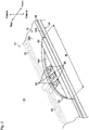
Fig. 1 is a perspective view showing how to assemble the connecting structure between a cowl louver and a windshield according to a first embodiment of the present invention. -
Fig. 2 is a perspective view showing, as an enlarged view, a cutout portion formed in the windshield, and surroundings of the cutout portion. -
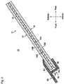
Fig. 3 is an enlarged sectional view showing the connecting structure except for the area where the cutout portion is formed. -
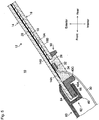
Fig. 4 is an enlarged sectional view showing the connecting structure at the area where the cutout portion is formed. -
Fig. 5 is an enlarged sectional view showing the connecting structure at the area where the cutout portion is formed, according to a modification of the first embodiment. -
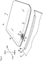
Fig. 6 is a perspective view showing how to assemble the connecting structure between a cowl louver and a windshield according to a second embodiment of the present invention. - Now, the present invention will be described based on embodiments of the present invention in reference to the accompanying drawings. It should be noted that numerous modifications and variations of the present invention are possible in light of the disclosure without departing from the scope of the present invention, and that the present invention may be practiced by other embodiments than the embodiments described below. From this point of view, any modifications within the scope of the present invention are included in the scope of the appended claims. In the drawings, portions or elements denoted by like references are basically similar portions or elements having similar functions.
- The connecting structure between a cowl louver and a windshield according to a first embodiment of the present invention will be described in reference to the accompanying drawings.
Fig. 1 is a view showing awindshield 10 and acowl louver 60 which are seen from an interior side. - In Description, the wordings "front", "rear", "upper", "lower", "interior" and "exterior" which indicate directions or positions mean positional relationships when the connecting structure between a cowl louver and a windshield is mounted to a vehicle.
- As shown in
Fig. 1 , thecowl louver 60 has a rear end portion connected to a lower edge portion of thewindshield 10. Thewindshield 10 includes a laminatedglass 12; acutout portion 26;electrodes 28,terminals 32 and aspacer 40 which are disposed in thecutout portion 26; andheating wires 22 for heating a lateral side portion and a lower side portion of the laminated glass. There is no particular limitation to the area where theheating wires 22 are disposed. - The laminated
glass 12 is a laminated glass which includes a first glass plate disposed on an exterior side, a second glass plate disposed on an interior side, both glass plates being bonded through an interlayer. - The
cowl louver 60 includes aclamping portion 62 at the rear end portion, which is defined by anupper member 64 disposed so as to extend along the first glass plate, and a plurality oflower members 66 disposed on a certain area of the cowl louver close to the second glass plate, and which is formed in a U-character shape in section. Theclamping portion 62 clamps thewindshield 10 by inserting the lower edge portion of thewindshield 10 into openings defined by theupper member 64 and thelower members 66. Theclamping portion 62 connects thewindshield 10 and thecowl louver 60. - As shown in
Fig. 2 , thewindshield 10 includes the laminatedglass 14 which has thefirst glass plate 14 disposed on the exterior side, thesecond glass plate 16 disposed on the interior side, and theinterlayer 18 bonding thefirst glass plate 14 and thesecond glass plate 16. As shown inFig. 2 , thefirst glass plate 14 has aninterior side surface 14A, and thesecond glass plate 16 has anexterior side surface 16A such that the interior and exterior side surfaces are bonded together by theinterlayer 18. - The
interlayer 18 may be an interlayer made of PVB (Polyvinyl butyral) or an interlayer made of EVA (Ethylene-Vinyl Acetate). - As shown in
Fig. 2 , theheating wires 22 are disposed on theinterior side surface 14A of thefirst glass plate 14. Theheating wires 22 are made by a conductive material, such as metal. There is no particular limitation to the metal. The metal may be, for example, gold, silver, nickel, copper, aluminum, tin, cobalt, or an allow containing at least one of these elements. Theheating wires 22 may be formed by baking conductive paste, such as metal paste. - As shown in
Fig. 2 , thewindshield 10 has thecutout portion 26 formed in a certain area of the lower edge portion. Thecutout portion 26 is an area where a portion of theinterior side surface 14A of thefirst glass plate 14 is exposed by removing a portion of thesecond glass plate 16 and a portion of theinterlayer 18. - The
plural electrodes 28, which are electrically connected to theheating wires 22 to provide a power feed portion, are disposed on theinterior side surface 14A in thecutout portion 26. Theelectrodes 28 may be formed by a similar process to theheating wires 22. In the first embodiment, thecutout portion 26 is formed in a substantially semi-circular shape such that the cutout portion has a length gradually increasing to a front end portion of the windshield. There is no particular limitation to the size or shape of thecutout portion 26 as long as the cutout portion is large enough to dispose theelectrodes 28 in a required number. - The
cutout portion 26 has thespacer 40 disposed therein on a position closer to the lower edge portion of the windshield than theelectrodes 28. As shown inFig. 2 , the spacer is formed in a substantially cubic shape. - When the
spacer 40 is disposed in thecutout portion 26, thespacer 40 functions as if the removed portion of thesecond glass plate 16 and the removed portion of theinterlayer 18 are present. As described later, the lower edge portion of thewindshield 10 can be clamped by theclamping portion 62 of thecowl louver 60 as in a certain area where thesecond glass plate 16 and theinterlayer 18 are present. - The
spacer 40 has a width W in a direction orthogonal to a front and rear direction of the windshield, which is preferably determined to be a length such that thespacer 40 has both end portions brought into contact with thesecond glass plate 16 and theinterlayer 18. - Now, explanation will be made about the connecting structure between the
cowl louver 60 and thewindshield 10. - As shown in
Fig. 3 , theclamping portion 62 clamps the lower edge portion of thewindshield 10 at the rear end portion of thecowl louver 60. When a portion of thewindshield 10 except for thecutout portion 26 is inserted into the openings defined by theupper member 64 and thelower members 66, theupper member 64 is brought into contact with anexterior side surface 14B of thefirst glass plate 14 while thelower members 66 are brought into contact with aninterior side surface 16B of thesecond glass plate 16. Thus, theclamping portion 62, which includes theupper member 64 and thelower members 66, pinches the lower edge portion of thewindshield 10. When each of the openings of the clampingportion 62 has a width set to be smaller than the thickness of thelaminated glass 12, it is possible to increase the clamping force of the clampingportion 62 applied to thewindshield 10. - It is preferred from the viewpoint of avoiding the formation of e.g. a conchoidal chip on a cut surface of a glass plate and of securing the safety in handling a
windshield 10 by a worker that thefirst glass plate 14 and thesecond glass plate 16 have afront end portion 14C and a front end portion 16C formed in a curved shape (chamfered), respectively. - As shown in
Fig. 4 , theelectrodes 28 are disposed on theinterior side surface 14A of thefirst glass plate 14 in thecutout portion 26. Theelectrodes 28 are electrically connected to theheating wires 22. Theconductors 30 are connected to theelectrodes 28 through theterminals 32. Theterminals 32 are connected to theelectrodes 28 by soldering. - As shown in
Fig. 4 , when thecutout portion 26 of thewindshield 10 is inserted into the openings defined by theupper member 64 and thelower members 66, theupper member 64 is brought into contact with theexterior side surface 14B of thefirst glass plate 14 while thelower members 66 are brought into contact with thespacer 40 at itstop surface portion 40A. Since the spacer functions as if the removed portion of thesecond glass plate 16 and the removed portion of theinterlayer 18 are present, the clampingportion 62 can clamp, at the lower edge portion of thecowl louver 60, a certain area of thewindshield 10 where thecutout portion 26 is formed in the lower edge portion. - The
spacer 40 has a height H reaching thetop surface portion 40A, which is equal to a height H1 of thesecond glass plate 16 reaching theinterior side surface 16B on the basis of theinterior side surface 14A of the first glass plate. From this point of view, thetop surface portion 40A of the spacer and theinterior side surface 16B of thesecond glass plate 16 at the lower edge portion of thewindshield 10 are preferred to be substantially flush with each other (form a substantially common plane). - In the first embodiment, the
spacer 40 and thefirst glass plate 14 may be bonded together by e.g. a double-sidedadhesive tape 42. There is no particular limitation to the bonding method as long as thespacer 40 and thefirst glass plate 14 can be bonded together with thetop surface portion 40A of thespacer 40 and theinterior side surface 16B of thesecond glass plate 16 having a substantially common plane each other. - Preferably, a
front end portion 40B of thespacer 40 and afront end portion 14C of thefirst glass plate 14 are flush with each other. The word "flush with" means "apparently flush with", "completely flush with" or "substantially flush with". Thespacer 40 can protect thefront end portion 14C of thefirst glass plate 14 to prevent thefirst glass plate 14 from being cracked or chipped. Further, it is easy to insert the lower edge portion of thewindshield 10 into the clampingportion 62. - Preferably, the shape on the interior side of the
front end portion 40B of thespacer 40 is the same shape as the shape on the interior side of the front end portion 16C of the second glass plate 16 (seeFig. 3 ). When the interior side surfaces of both front end portions are formed in the same shape, it is possible to reliably insert thewindshield 10 into the clampingportion 62 at any position of the lower edge portion of thewindshield 10. The wording "the same shape" means "exactly the same shape" or "substantially the same shape". Thefront end portion 40B of thespacer 40 is preferably formed in a curved shape as in the front end portion 16C of thesecond glass plate 16. Thus, it is easy to insert thewindshield 10 into the clampingportion 62. - It is sufficient that the
spacer 40 has a depth D in the front and rear direction such that the spacer is clamped by tip portions of thelower members 66 of the clampingportion 62. Although thefront end portion 14C of thefirst glass plate 14 is preferably flush with thefront end portion 40B of thespace 40, the former may fail to be flush with the latter. - The
spacer 40 is preferably made of a material selected from a group comprising of a synthetic resin, metal, glass and rubber. The synthetic resin is preferred to be a TPE (thermoplastic elastomer) resin. When a TPE resin is used, the TPE resin has a shore hardness of preferably at least Hs70. Thus, thespacer 40 is prevented from being deformed by alower member 66 when thewindshield 10 is inserted into the clampingportion 62. Thespacer 40 may, however, be made of a different material or have a different shore hardness. - In the first embodiment, a
sealant 34 is filled between thespacer 40 and a combination of thesecond glass plate 16 and theinterlayer 18 in thecutout portion 26. Thesealant 34 may be, for example, a silicone resin. Thesealant 34 seals and protects a portion of eachconductor 30, theelectrodes 28 and theterminals 32. - Next, explanation will be made about a modification of the first embodiment in reference to
Fig. 5 . Portions or elements similar to those of the first embodiment are denoted by like references, and explanation about these portions or elements will be omitted. - As shown in
Fig. 5 , thecutout portion 26 of thewindshield 10 is inserted into the openings defined by theupper member 64 and thelower members 66, theupper member 64 is brought into contact with theexterior side surface 14B of thefirst glass plate 14 while thelower members 66 are brought into contact with thetop surface portion 40A flush with theinterior side surface 16B of the second glass plate. Thus, the clampingportion 62 clamps thefirst glass plate 14 and thespacer 40. - In the modification of the first embodiment, the
second glass plate 16 has adam 50 disposed on theinterior side surface 16B around thecutout portion 26. Further, thespacer 40 is formed in an L-character shape as seen in section such that the spacer has a protrudingportion 40C protruding toward the interior side in comparison with thetop surface portion 40A at a portion that is not clamped by thelower members 66. - Since the
dam 50 and the L-character shape ofspacer 40 prevent thesealant 34 from flowing out, the modification of the first embodiment allows thesealant 34 to be filled in a greater amount in comparison with the first embodiment. When thesealant 34 is filled in a greater amount, it is possible to more reliably protect the relevant portion of eachconductor 30, theelectrodes 28 and theterminals 32. Further, it is possible to lead out theconductors 30 beyond the protrudingportion 40C because of the presence of the L-character shape ofspacer 40. Thus, thespacer 40 prevents the clampingportion 62 from nipping aconductors 30. - There is no limitation to the shape of the spacer as long as the
spacer 40 has the protrudingportion 40C protruding toward the interior side in comparison with thetop surface portion 40A at such a portion that is not clamped by thelower members 66. Thespacer 40 may be, for example, formed in a T-character shape. - The connecting structure between a cowl louver and a windshield according to a second embodiment will be described in reference to
Fig. 6 . Portions or elements similar to those of the connecting structure between a cowl louver and a windshield according to the first embodiment are denoted by like references, and explanation of these portions or elements may be omitted. - As shown in
Fig. 6 , acowl louver 60 has a rear end portion connected to a lower edge portion of awindshield 10. Thewindshield 10 includes alaminated glass 12; acutout portion 26;electrodes 28,terminals 32 and aspacer 40 which are disposed in thecutout portion 26; andheating wires 22 for heating a lateral side portion and a lower side portion of the laminated glass. - The
windshield 10 with the cowl louver according to the second embodiment is different from the connecting structure between thecowl louver 60 and thewindshield 10 according to the first embodiment in that thecowl louver 60 of the former has a clamping portion formed with alower member 66 formed in a different shape from that of the first embodiment. - The
cowl louver 60 includes the clampingportion 62 formed in a U-character shape in section at the rear end portion, which is defined by anupper member 64 disposed so as to extend along afirst glass plate 14, and thelower member 66 disposed so as to extend along asecond glass plate 16. Thelower member 66 is formed so as to continuously extend in the width direction of thecowl louver 60. - In the second embodiment, the
entire clamping portion 62 clamps the lower edge portion of the windshield 10 (a certain area of the lower edge portion where thecutout portion 26 is formed, and a certain area of the lower edge portion where thecutout portion 26 is not formed). Since thelower member 66 is formed so as to have a continuous length, it is possible to more effectively prevent moisture from entering the interior side. - The entire disclosure of Japanese Patent Application No.
2017-078962 filed on April 12, 2017
Claims (9)
- A connecting structure between a cowl louver and a windshield such that the cowl louver has a rear end portion connected to a lower edge portion of the windshield, comprising:
a windshield including:a laminated glass having a first glass plate disposed on an exterior side, a second glass plate disposed on an interior side and an interlayer bonding the first glass plate and the second glass plate;the laminated glass having a cutout portion formed by removing a part of the second glass plate and the interlayer at a certain area of a lower edge portion of the laminated glass;the first glass having a power feed portion disposed on an interior side surface thereof in the cutout portion;a spacer disposed in the cutout portion on a lower edge side of the windshield closer than the power feed portion; andthe cowl louver including a clamping portion formed in a U-character shape in section at a rear end portion thereof, the clamping portion having an upper member disposed along the first glass plate and a lower member disposed so as to be close to the second glass plate; andthe clamping portion clamps the first glass plate and the spacer. - The connecting structure according to Claim 1, wherein the spacer is clamped by a tip portion of the lower member of the claiming portion.
- The connecting structure according to Claim 1 or 2, wherein a front end portion of the spacer and a front end portion of the first glass plate are flush with each other.
- The connecting structure according to any one of Claims 1 to 3, wherein the spacer is made of a material selected from a group comprising a synthetic resin, metal, glass and rubber.
- The connecting structure according to any one of Claims 1 to 4, wherein the cutout portion has a sealant therein to seal the power feed portion.
- The connecting structure according to any one of Claims 1 to 5, wherein the spacer has a protruding portion protruding toward the interior side in comparison with the top surface portion at a portion that is not clamped by the lower member.
- The connecting structure according to any one of Claims 1 to 6, wherein the lower member is disposed along the second glass plate.
- The connecting structure according to any one of Claims 1 to 7, wherein the shape on the interior side of the front end portion of the spacer is the same shape as the shape on the interior side of the front end portion of the second glass plate except for the cutout portion.
- The connecting structure according to Claim 8, wherein the front end portion of the spacer has the interior side surface formed in a curved shape.
Applications Claiming Priority (1)
| Application Number | Priority Date | Filing Date | Title |
|---|---|---|---|
| JP2017078962A JP6880957B2 (en) | 2017-04-12 | 2017-04-12 | Articulation structure of cowl louver and windshield |
Publications (2)
| Publication Number | Publication Date |
|---|---|
| EP3388270A1 true EP3388270A1 (en) | 2018-10-17 |
| EP3388270B1 EP3388270B1 (en) | 2021-08-11 |
Family
ID=61873253
Family Applications (1)
| Application Number | Title | Priority Date | Filing Date |
|---|---|---|---|
| EP18000302.2A Active EP3388270B1 (en) | 2017-04-12 | 2018-03-28 | Connecting structure between a cowl louver and a windshield |
Country Status (4)
| Country | Link |
|---|---|
| US (1) | US10569628B2 (en) |
| EP (1) | EP3388270B1 (en) |
| JP (1) | JP6880957B2 (en) |
| CN (1) | CN108688447B (en) |
Cited By (1)
| Publication number | Priority date | Publication date | Assignee | Title |
|---|---|---|---|---|
| CN116057026A (en) * | 2020-08-19 | 2023-05-02 | Agc株式会社 | window glass for vehicles |
Families Citing this family (3)
| Publication number | Priority date | Publication date | Assignee | Title |
|---|---|---|---|---|
| DE112018002207T5 (en) * | 2017-04-28 | 2020-02-20 | AGC Inc. | Windshield with a molded part and connection structure for a cowl element and a windshield with a molded part |
| DE112021001969B4 (en) * | 2020-06-02 | 2024-11-14 | AGC Inc. | CONNECTING STRUCTURE FOR A COWL COVER AND A WINDSHIELD WITH A MOLDED PART |
| JP7486050B2 (en) * | 2020-07-01 | 2024-05-17 | Agc株式会社 | Vehicle window glass and method for manufacturing vehicle window glass |
Citations (3)
| Publication number | Priority date | Publication date | Assignee | Title |
|---|---|---|---|---|
| JPH0597061A (en) | 1991-05-14 | 1993-04-20 | Toyoda Gosei Co Ltd | Cowl louver |
| WO2013114855A1 (en) * | 2012-01-31 | 2013-08-08 | 日本板硝子株式会社 | Seal member-equipped window glass |
| US20140374401A1 (en) * | 2013-06-20 | 2014-12-25 | Nippon Sheet Glass Co., Ltd. | Automotive glazing and method of manufacturing same |
Family Cites Families (14)
| Publication number | Priority date | Publication date | Assignee | Title |
|---|---|---|---|---|
| JPS5859340A (en) | 1981-10-02 | 1983-04-08 | Nissan Motor Co Ltd | Piston for automobile engine |
| JPS5917928A (en) | 1982-06-30 | 1984-01-30 | 「はま」本 春見 | Breeding of oyster |
| JPS6211823A (en) | 1985-07-10 | 1987-01-20 | Mitsubishi Electric Corp | Polarized light converter |
| JPS6325618A (en) | 1986-07-18 | 1988-02-03 | Mitsubishi Electric Corp | Beam splitter device |
| JP2005001505A (en) * | 2003-06-11 | 2005-01-06 | Asmo Co Ltd | Vehicle front structure |
| JP4433993B2 (en) * | 2004-11-24 | 2010-03-17 | トヨタ自動車株式会社 | Windshield glass mounting structure to cowl louver |
| JP2010064518A (en) * | 2008-09-08 | 2010-03-25 | Nippon Plast Co Ltd | Mounting structure of cowl top cover |
| JP2010264868A (en) * | 2009-05-14 | 2010-11-25 | Toyota Motor Corp | Cowl louver structure for vehicles |
| JP5621546B2 (en) | 2010-11-25 | 2014-11-12 | トヨタ自動車株式会社 | Cowl louver fixing structure for vehicles |
| JP2012240454A (en) * | 2011-05-16 | 2012-12-10 | Toyota Motor Corp | Fixing molding and fixing structure for vehicle cowl louver |
| JP5859340B2 (en) | 2012-02-27 | 2016-02-10 | 日本板硝子株式会社 | Window glass with seal member |
| US10414378B2 (en) * | 2013-07-02 | 2019-09-17 | Pilkington Group Limited | Window assembly |
| JP6314440B2 (en) | 2013-11-19 | 2018-04-25 | スズキ株式会社 | Mall mounting structure |
| JP6252562B2 (en) * | 2015-07-31 | 2017-12-27 | トヨタ自動車株式会社 | Windshield glass peripheral structure |
-
2017
- 2017-04-12 JP JP2017078962A patent/JP6880957B2/en active Active
-
2018
- 2018-03-28 EP EP18000302.2A patent/EP3388270B1/en active Active
- 2018-04-04 US US15/944,884 patent/US10569628B2/en active Active
- 2018-04-11 CN CN201810319722.1A patent/CN108688447B/en active Active
Patent Citations (3)
| Publication number | Priority date | Publication date | Assignee | Title |
|---|---|---|---|---|
| JPH0597061A (en) | 1991-05-14 | 1993-04-20 | Toyoda Gosei Co Ltd | Cowl louver |
| WO2013114855A1 (en) * | 2012-01-31 | 2013-08-08 | 日本板硝子株式会社 | Seal member-equipped window glass |
| US20140374401A1 (en) * | 2013-06-20 | 2014-12-25 | Nippon Sheet Glass Co., Ltd. | Automotive glazing and method of manufacturing same |
Cited By (1)
| Publication number | Priority date | Publication date | Assignee | Title |
|---|---|---|---|---|
| CN116057026A (en) * | 2020-08-19 | 2023-05-02 | Agc株式会社 | window glass for vehicles |
Also Published As
| Publication number | Publication date |
|---|---|
| CN108688447A (en) | 2018-10-23 |
| US20180297459A1 (en) | 2018-10-18 |
| JP6880957B2 (en) | 2021-06-02 |
| JP2018176978A (en) | 2018-11-15 |
| CN108688447B (en) | 2023-08-04 |
| EP3388270B1 (en) | 2021-08-11 |
| US10569628B2 (en) | 2020-02-25 |
Similar Documents
| Publication | Publication Date | Title |
|---|---|---|
| US10569628B2 (en) | Connecting structure between a cowl louver and a windshield | |
| DK2585291T3 (en) | Laminated glass with electrical function and connection element | |
| JP7023768B2 (en) | A fluid-sealed enclosure for electrical connections in windows | |
| US9172191B2 (en) | Housing for electrical connection between a foil conductor and a conductor | |
| KR20150068385A (en) | Laminated glazing | |
| KR102728036B1 (en) | Connection device using flexible flat cable | |
| US20200001829A1 (en) | Window Assembly | |
| US10858875B2 (en) | Assembly having a window support for a vehicle window | |
| JP6914809B2 (en) | Windshield for vehicles | |
| KR102742921B1 (en) | Flat conductor connecting element | |
| EP2982507B1 (en) | An electrically heated laminated window | |
| US11490465B2 (en) | Window assembly having a terminal connector | |
| CN112334427B (en) | Sandwich glass for automobile | |
| US20250350048A1 (en) | Electrical line connection for electrical contacting | |
| CN117693867A (en) | Wire connections for electrical contact | |
| CN119422291A (en) | Connecting device and electrical line connection with flat conductor connecting element |
Legal Events
| Date | Code | Title | Description |
|---|---|---|---|
| PUAI | Public reference made under article 153(3) epc to a published international application that has entered the european phase |
Free format text: ORIGINAL CODE: 0009012 |
|
| STAA | Information on the status of an ep patent application or granted ep patent |
Free format text: STATUS: THE APPLICATION HAS BEEN PUBLISHED |
|
| AK | Designated contracting states |
Kind code of ref document: A1 Designated state(s): AL AT BE BG CH CY CZ DE DK EE ES FI FR GB GR HR HU IE IS IT LI LT LU LV MC MK MT NL NO PL PT RO RS SE SI SK SM TR |
|
| AX | Request for extension of the european patent |
Extension state: BA ME |
|
| STAA | Information on the status of an ep patent application or granted ep patent |
Free format text: STATUS: REQUEST FOR EXAMINATION WAS MADE |
|
| 17P | Request for examination filed |
Effective date: 20190411 |
|
| RBV | Designated contracting states (corrected) |
Designated state(s): AL AT BE BG CH CY CZ DE DK EE ES FI FR GB GR HR HU IE IS IT LI LT LU LV MC MK MT NL NO PL PT RO RS SE SI SK SM TR |
|
| STAA | Information on the status of an ep patent application or granted ep patent |
Free format text: STATUS: EXAMINATION IS IN PROGRESS |
|
| 17Q | First examination report despatched |
Effective date: 20191220 |
|
| GRAP | Despatch of communication of intention to grant a patent |
Free format text: ORIGINAL CODE: EPIDOSNIGR1 |
|
| STAA | Information on the status of an ep patent application or granted ep patent |
Free format text: STATUS: GRANT OF PATENT IS INTENDED |
|
| INTG | Intention to grant announced |
Effective date: 20210305 |
|
| GRAS | Grant fee paid |
Free format text: ORIGINAL CODE: EPIDOSNIGR3 |
|
| GRAA | (expected) grant |
Free format text: ORIGINAL CODE: 0009210 |
|
| STAA | Information on the status of an ep patent application or granted ep patent |
Free format text: STATUS: THE PATENT HAS BEEN GRANTED |
|
| AK | Designated contracting states |
Kind code of ref document: B1 Designated state(s): AL AT BE BG CH CY CZ DE DK EE ES FI FR GB GR HR HU IE IS IT LI LT LU LV MC MK MT NL NO PL PT RO RS SE SI SK SM TR |
|
| REG | Reference to a national code |
Ref country code: CH Ref legal event code: EP |
|
| REG | Reference to a national code |
Ref country code: DE Ref legal event code: R096 Ref document number: 602018021444 Country of ref document: DE |
|
| REG | Reference to a national code |
Ref country code: IE Ref legal event code: FG4D Ref country code: AT Ref legal event code: REF Ref document number: 1419035 Country of ref document: AT Kind code of ref document: T Effective date: 20210915 |
|
| REG | Reference to a national code |
Ref country code: LT Ref legal event code: MG9D |
|
| REG | Reference to a national code |
Ref country code: NL Ref legal event code: MP Effective date: 20210811 |
|
| REG | Reference to a national code |
Ref country code: AT Ref legal event code: MK05 Ref document number: 1419035 Country of ref document: AT Kind code of ref document: T Effective date: 20210811 |
|
| PG25 | Lapsed in a contracting state [announced via postgrant information from national office to epo] |
Ref country code: SE Free format text: LAPSE BECAUSE OF FAILURE TO SUBMIT A TRANSLATION OF THE DESCRIPTION OR TO PAY THE FEE WITHIN THE PRESCRIBED TIME-LIMIT Effective date: 20210811 Ref country code: LT Free format text: LAPSE BECAUSE OF FAILURE TO SUBMIT A TRANSLATION OF THE DESCRIPTION OR TO PAY THE FEE WITHIN THE PRESCRIBED TIME-LIMIT Effective date: 20210811 Ref country code: BG Free format text: LAPSE BECAUSE OF FAILURE TO SUBMIT A TRANSLATION OF THE DESCRIPTION OR TO PAY THE FEE WITHIN THE PRESCRIBED TIME-LIMIT Effective date: 20211111 Ref country code: AT Free format text: LAPSE BECAUSE OF FAILURE TO SUBMIT A TRANSLATION OF THE DESCRIPTION OR TO PAY THE FEE WITHIN THE PRESCRIBED TIME-LIMIT Effective date: 20210811 Ref country code: NO Free format text: LAPSE BECAUSE OF FAILURE TO SUBMIT A TRANSLATION OF THE DESCRIPTION OR TO PAY THE FEE WITHIN THE PRESCRIBED TIME-LIMIT Effective date: 20211111 Ref country code: PT Free format text: LAPSE BECAUSE OF FAILURE TO SUBMIT A TRANSLATION OF THE DESCRIPTION OR TO PAY THE FEE WITHIN THE PRESCRIBED TIME-LIMIT Effective date: 20211213 Ref country code: HR Free format text: LAPSE BECAUSE OF FAILURE TO SUBMIT A TRANSLATION OF THE DESCRIPTION OR TO PAY THE FEE WITHIN THE PRESCRIBED TIME-LIMIT Effective date: 20210811 Ref country code: FI Free format text: LAPSE BECAUSE OF FAILURE TO SUBMIT A TRANSLATION OF THE DESCRIPTION OR TO PAY THE FEE WITHIN THE PRESCRIBED TIME-LIMIT Effective date: 20210811 Ref country code: ES Free format text: LAPSE BECAUSE OF FAILURE TO SUBMIT A TRANSLATION OF THE DESCRIPTION OR TO PAY THE FEE WITHIN THE PRESCRIBED TIME-LIMIT Effective date: 20210811 Ref country code: RS Free format text: LAPSE BECAUSE OF FAILURE TO SUBMIT A TRANSLATION OF THE DESCRIPTION OR TO PAY THE FEE WITHIN THE PRESCRIBED TIME-LIMIT Effective date: 20210811 |
|
| PG25 | Lapsed in a contracting state [announced via postgrant information from national office to epo] |
Ref country code: PL Free format text: LAPSE BECAUSE OF FAILURE TO SUBMIT A TRANSLATION OF THE DESCRIPTION OR TO PAY THE FEE WITHIN THE PRESCRIBED TIME-LIMIT Effective date: 20210811 Ref country code: LV Free format text: LAPSE BECAUSE OF FAILURE TO SUBMIT A TRANSLATION OF THE DESCRIPTION OR TO PAY THE FEE WITHIN THE PRESCRIBED TIME-LIMIT Effective date: 20210811 Ref country code: GR Free format text: LAPSE BECAUSE OF FAILURE TO SUBMIT A TRANSLATION OF THE DESCRIPTION OR TO PAY THE FEE WITHIN THE PRESCRIBED TIME-LIMIT Effective date: 20211112 |
|
| PG25 | Lapsed in a contracting state [announced via postgrant information from national office to epo] |
Ref country code: NL Free format text: LAPSE BECAUSE OF FAILURE TO SUBMIT A TRANSLATION OF THE DESCRIPTION OR TO PAY THE FEE WITHIN THE PRESCRIBED TIME-LIMIT Effective date: 20210811 |
|
| PG25 | Lapsed in a contracting state [announced via postgrant information from national office to epo] |
Ref country code: DK Free format text: LAPSE BECAUSE OF FAILURE TO SUBMIT A TRANSLATION OF THE DESCRIPTION OR TO PAY THE FEE WITHIN THE PRESCRIBED TIME-LIMIT Effective date: 20210811 |
|
| REG | Reference to a national code |
Ref country code: DE Ref legal event code: R097 Ref document number: 602018021444 Country of ref document: DE |
|
| PG25 | Lapsed in a contracting state [announced via postgrant information from national office to epo] |
Ref country code: SM Free format text: LAPSE BECAUSE OF FAILURE TO SUBMIT A TRANSLATION OF THE DESCRIPTION OR TO PAY THE FEE WITHIN THE PRESCRIBED TIME-LIMIT Effective date: 20210811 Ref country code: SK Free format text: LAPSE BECAUSE OF FAILURE TO SUBMIT A TRANSLATION OF THE DESCRIPTION OR TO PAY THE FEE WITHIN THE PRESCRIBED TIME-LIMIT Effective date: 20210811 Ref country code: RO Free format text: LAPSE BECAUSE OF FAILURE TO SUBMIT A TRANSLATION OF THE DESCRIPTION OR TO PAY THE FEE WITHIN THE PRESCRIBED TIME-LIMIT Effective date: 20210811 Ref country code: EE Free format text: LAPSE BECAUSE OF FAILURE TO SUBMIT A TRANSLATION OF THE DESCRIPTION OR TO PAY THE FEE WITHIN THE PRESCRIBED TIME-LIMIT Effective date: 20210811 Ref country code: CZ Free format text: LAPSE BECAUSE OF FAILURE TO SUBMIT A TRANSLATION OF THE DESCRIPTION OR TO PAY THE FEE WITHIN THE PRESCRIBED TIME-LIMIT Effective date: 20210811 Ref country code: AL Free format text: LAPSE BECAUSE OF FAILURE TO SUBMIT A TRANSLATION OF THE DESCRIPTION OR TO PAY THE FEE WITHIN THE PRESCRIBED TIME-LIMIT Effective date: 20210811 |
|
| PLBE | No opposition filed within time limit |
Free format text: ORIGINAL CODE: 0009261 |
|
| STAA | Information on the status of an ep patent application or granted ep patent |
Free format text: STATUS: NO OPPOSITION FILED WITHIN TIME LIMIT |
|
| 26N | No opposition filed |
Effective date: 20220512 |
|
| PG25 | Lapsed in a contracting state [announced via postgrant information from national office to epo] |
Ref country code: IT Free format text: LAPSE BECAUSE OF FAILURE TO SUBMIT A TRANSLATION OF THE DESCRIPTION OR TO PAY THE FEE WITHIN THE PRESCRIBED TIME-LIMIT Effective date: 20210811 |
|
| PG25 | Lapsed in a contracting state [announced via postgrant information from national office to epo] |
Ref country code: SI Free format text: LAPSE BECAUSE OF FAILURE TO SUBMIT A TRANSLATION OF THE DESCRIPTION OR TO PAY THE FEE WITHIN THE PRESCRIBED TIME-LIMIT Effective date: 20210811 |
|
| PG25 | Lapsed in a contracting state [announced via postgrant information from national office to epo] |
Ref country code: MC Free format text: LAPSE BECAUSE OF FAILURE TO SUBMIT A TRANSLATION OF THE DESCRIPTION OR TO PAY THE FEE WITHIN THE PRESCRIBED TIME-LIMIT Effective date: 20210811 |
|
| REG | Reference to a national code |
Ref country code: CH Ref legal event code: PL |
|
| GBPC | Gb: european patent ceased through non-payment of renewal fee |
Effective date: 20220328 |
|
| REG | Reference to a national code |
Ref country code: BE Ref legal event code: MM Effective date: 20220331 |
|
| PG25 | Lapsed in a contracting state [announced via postgrant information from national office to epo] |
Ref country code: LU Free format text: LAPSE BECAUSE OF NON-PAYMENT OF DUE FEES Effective date: 20220328 Ref country code: LI Free format text: LAPSE BECAUSE OF NON-PAYMENT OF DUE FEES Effective date: 20220331 Ref country code: IE Free format text: LAPSE BECAUSE OF NON-PAYMENT OF DUE FEES Effective date: 20220328 Ref country code: GB Free format text: LAPSE BECAUSE OF NON-PAYMENT OF DUE FEES Effective date: 20220328 Ref country code: FR Free format text: LAPSE BECAUSE OF NON-PAYMENT OF DUE FEES Effective date: 20220331 Ref country code: CH Free format text: LAPSE BECAUSE OF NON-PAYMENT OF DUE FEES Effective date: 20220331 |
|
| PG25 | Lapsed in a contracting state [announced via postgrant information from national office to epo] |
Ref country code: BE Free format text: LAPSE BECAUSE OF NON-PAYMENT OF DUE FEES Effective date: 20220331 |
|
| PG25 | Lapsed in a contracting state [announced via postgrant information from national office to epo] |
Ref country code: HU Free format text: LAPSE BECAUSE OF FAILURE TO SUBMIT A TRANSLATION OF THE DESCRIPTION OR TO PAY THE FEE WITHIN THE PRESCRIBED TIME-LIMIT; INVALID AB INITIO Effective date: 20180328 |
|
| PG25 | Lapsed in a contracting state [announced via postgrant information from national office to epo] |
Ref country code: MK Free format text: LAPSE BECAUSE OF FAILURE TO SUBMIT A TRANSLATION OF THE DESCRIPTION OR TO PAY THE FEE WITHIN THE PRESCRIBED TIME-LIMIT Effective date: 20210811 Ref country code: CY Free format text: LAPSE BECAUSE OF FAILURE TO SUBMIT A TRANSLATION OF THE DESCRIPTION OR TO PAY THE FEE WITHIN THE PRESCRIBED TIME-LIMIT Effective date: 20210811 |
|
| PG25 | Lapsed in a contracting state [announced via postgrant information from national office to epo] |
Ref country code: MT Free format text: LAPSE BECAUSE OF FAILURE TO SUBMIT A TRANSLATION OF THE DESCRIPTION OR TO PAY THE FEE WITHIN THE PRESCRIBED TIME-LIMIT Effective date: 20210811 |
|
| PG25 | Lapsed in a contracting state [announced via postgrant information from national office to epo] |
Ref country code: TR Free format text: LAPSE BECAUSE OF FAILURE TO SUBMIT A TRANSLATION OF THE DESCRIPTION OR TO PAY THE FEE WITHIN THE PRESCRIBED TIME-LIMIT Effective date: 20210811 |
|
| PGFP | Annual fee paid to national office [announced via postgrant information from national office to epo] |
Ref country code: DE Payment date: 20260319 Year of fee payment: 9 |