EP3388193A1 - Cryogenic machining process using nanofluid - Google Patents
Cryogenic machining process using nanofluid Download PDFInfo
- Publication number
- EP3388193A1 EP3388193A1 EP18166410.3A EP18166410A EP3388193A1 EP 3388193 A1 EP3388193 A1 EP 3388193A1 EP 18166410 A EP18166410 A EP 18166410A EP 3388193 A1 EP3388193 A1 EP 3388193A1
- Authority
- EP
- European Patent Office
- Prior art keywords
- nanofluid
- nanoparticles
- machining process
- fluid
- metal
- Prior art date
- Legal status (The legal status is an assumption and is not a legal conclusion. Google has not performed a legal analysis and makes no representation as to the accuracy of the status listed.)
- Granted
Links
Images

Classifications
-
- B—PERFORMING OPERATIONS; TRANSPORTING
- B23—MACHINE TOOLS; METAL-WORKING NOT OTHERWISE PROVIDED FOR
- B23Q—DETAILS, COMPONENTS, OR ACCESSORIES FOR MACHINE TOOLS, e.g. ARRANGEMENTS FOR COPYING OR CONTROLLING; MACHINE TOOLS IN GENERAL CHARACTERISED BY THE CONSTRUCTION OF PARTICULAR DETAILS OR COMPONENTS; COMBINATIONS OR ASSOCIATIONS OF METAL-WORKING MACHINES, NOT DIRECTED TO A PARTICULAR RESULT
- B23Q11/00—Accessories fitted to machine tools for keeping tools or parts of the machine in good working condition or for cooling work; Safety devices specially combined with or arranged in, or specially adapted for use in connection with, machine tools
- B23Q11/10—Arrangements for cooling or lubricating tools or work
- B23Q11/1038—Arrangements for cooling or lubricating tools or work using cutting liquids with special characteristics, e.g. flow rate, quality
- B23Q11/1061—Arrangements for cooling or lubricating tools or work using cutting liquids with special characteristics, e.g. flow rate, quality using cutting liquids with specially selected composition or state of aggregation
-
- B—PERFORMING OPERATIONS; TRANSPORTING
- B23—MACHINE TOOLS; METAL-WORKING NOT OTHERWISE PROVIDED FOR
- B23Q—DETAILS, COMPONENTS, OR ACCESSORIES FOR MACHINE TOOLS, e.g. ARRANGEMENTS FOR COPYING OR CONTROLLING; MACHINE TOOLS IN GENERAL CHARACTERISED BY THE CONSTRUCTION OF PARTICULAR DETAILS OR COMPONENTS; COMBINATIONS OR ASSOCIATIONS OF METAL-WORKING MACHINES, NOT DIRECTED TO A PARTICULAR RESULT
- B23Q11/00—Accessories fitted to machine tools for keeping tools or parts of the machine in good working condition or for cooling work; Safety devices specially combined with or arranged in, or specially adapted for use in connection with, machine tools
- B23Q11/10—Arrangements for cooling or lubricating tools or work
- B23Q11/1038—Arrangements for cooling or lubricating tools or work using cutting liquids with special characteristics, e.g. flow rate, quality
- B23Q11/1053—Arrangements for cooling or lubricating tools or work using cutting liquids with special characteristics, e.g. flow rate, quality using the cutting liquid at specially selected temperatures
-
- C—CHEMISTRY; METALLURGY
- C10—PETROLEUM, GAS OR COKE INDUSTRIES; TECHNICAL GASES CONTAINING CARBON MONOXIDE; FUELS; LUBRICANTS; PEAT
- C10M—LUBRICATING COMPOSITIONS; USE OF CHEMICAL SUBSTANCES EITHER ALONE OR AS LUBRICATING INGREDIENTS IN A LUBRICATING COMPOSITION
- C10M125/00—Lubricating compositions characterised by the additive being an inorganic material
-
- C—CHEMISTRY; METALLURGY
- C10—PETROLEUM, GAS OR COKE INDUSTRIES; TECHNICAL GASES CONTAINING CARBON MONOXIDE; FUELS; LUBRICANTS; PEAT
- C10M—LUBRICATING COMPOSITIONS; USE OF CHEMICAL SUBSTANCES EITHER ALONE OR AS LUBRICATING INGREDIENTS IN A LUBRICATING COMPOSITION
- C10M125/00—Lubricating compositions characterised by the additive being an inorganic material
- C10M125/02—Carbon; Graphite
-
- C—CHEMISTRY; METALLURGY
- C10—PETROLEUM, GAS OR COKE INDUSTRIES; TECHNICAL GASES CONTAINING CARBON MONOXIDE; FUELS; LUBRICANTS; PEAT
- C10M—LUBRICATING COMPOSITIONS; USE OF CHEMICAL SUBSTANCES EITHER ALONE OR AS LUBRICATING INGREDIENTS IN A LUBRICATING COMPOSITION
- C10M125/00—Lubricating compositions characterised by the additive being an inorganic material
- C10M125/04—Metals; Alloys
-
- C—CHEMISTRY; METALLURGY
- C10—PETROLEUM, GAS OR COKE INDUSTRIES; TECHNICAL GASES CONTAINING CARBON MONOXIDE; FUELS; LUBRICANTS; PEAT
- C10M—LUBRICATING COMPOSITIONS; USE OF CHEMICAL SUBSTANCES EITHER ALONE OR AS LUBRICATING INGREDIENTS IN A LUBRICATING COMPOSITION
- C10M125/00—Lubricating compositions characterised by the additive being an inorganic material
- C10M125/08—Metal carbides or hydrides
-
- C—CHEMISTRY; METALLURGY
- C10—PETROLEUM, GAS OR COKE INDUSTRIES; TECHNICAL GASES CONTAINING CARBON MONOXIDE; FUELS; LUBRICANTS; PEAT
- C10M—LUBRICATING COMPOSITIONS; USE OF CHEMICAL SUBSTANCES EITHER ALONE OR AS LUBRICATING INGREDIENTS IN A LUBRICATING COMPOSITION
- C10M125/00—Lubricating compositions characterised by the additive being an inorganic material
- C10M125/18—Compounds containing halogen
-
- C—CHEMISTRY; METALLURGY
- C10—PETROLEUM, GAS OR COKE INDUSTRIES; TECHNICAL GASES CONTAINING CARBON MONOXIDE; FUELS; LUBRICANTS; PEAT
- C10M—LUBRICATING COMPOSITIONS; USE OF CHEMICAL SUBSTANCES EITHER ALONE OR AS LUBRICATING INGREDIENTS IN A LUBRICATING COMPOSITION
- C10M125/00—Lubricating compositions characterised by the additive being an inorganic material
- C10M125/20—Compounds containing nitrogen
-
- C—CHEMISTRY; METALLURGY
- C10—PETROLEUM, GAS OR COKE INDUSTRIES; TECHNICAL GASES CONTAINING CARBON MONOXIDE; FUELS; LUBRICANTS; PEAT
- C10M—LUBRICATING COMPOSITIONS; USE OF CHEMICAL SUBSTANCES EITHER ALONE OR AS LUBRICATING INGREDIENTS IN A LUBRICATING COMPOSITION
- C10M125/00—Lubricating compositions characterised by the additive being an inorganic material
- C10M125/22—Compounds containing sulfur, selenium or tellurium
-
- C—CHEMISTRY; METALLURGY
- C10—PETROLEUM, GAS OR COKE INDUSTRIES; TECHNICAL GASES CONTAINING CARBON MONOXIDE; FUELS; LUBRICANTS; PEAT
- C10M—LUBRICATING COMPOSITIONS; USE OF CHEMICAL SUBSTANCES EITHER ALONE OR AS LUBRICATING INGREDIENTS IN A LUBRICATING COMPOSITION
- C10M125/00—Lubricating compositions characterised by the additive being an inorganic material
- C10M125/26—Compounds containing silicon or boron, e.g. silica, sand
-
- C—CHEMISTRY; METALLURGY
- C10—PETROLEUM, GAS OR COKE INDUSTRIES; TECHNICAL GASES CONTAINING CARBON MONOXIDE; FUELS; LUBRICANTS; PEAT
- C10M—LUBRICATING COMPOSITIONS; USE OF CHEMICAL SUBSTANCES EITHER ALONE OR AS LUBRICATING INGREDIENTS IN A LUBRICATING COMPOSITION
- C10M171/00—Lubricating compositions characterised by purely physical criteria, e.g. containing as base-material, thickener or additive, ingredients which are characterised exclusively by their numerically specified physical properties, i.e. containing ingredients which are physically well-defined but for which the chemical nature is either unspecified or only very vaguely indicated
- C10M171/06—Particles of special shape or size
-
- B—PERFORMING OPERATIONS; TRANSPORTING
- B23—MACHINE TOOLS; METAL-WORKING NOT OTHERWISE PROVIDED FOR
- B23C—MILLING
- B23C2250/00—Compensating adverse effects during milling
- B23C2250/12—Cooling and lubrication
-
- B—PERFORMING OPERATIONS; TRANSPORTING
- B23—MACHINE TOOLS; METAL-WORKING NOT OTHERWISE PROVIDED FOR
- B23Q—DETAILS, COMPONENTS, OR ACCESSORIES FOR MACHINE TOOLS, e.g. ARRANGEMENTS FOR COPYING OR CONTROLLING; MACHINE TOOLS IN GENERAL CHARACTERISED BY THE CONSTRUCTION OF PARTICULAR DETAILS OR COMPONENTS; COMBINATIONS OR ASSOCIATIONS OF METAL-WORKING MACHINES, NOT DIRECTED TO A PARTICULAR RESULT
- B23Q11/00—Accessories fitted to machine tools for keeping tools or parts of the machine in good working condition or for cooling work; Safety devices specially combined with or arranged in, or specially adapted for use in connection with, machine tools
- B23Q11/12—Arrangements for cooling or lubricating parts of the machine
- B23Q11/126—Arrangements for cooling or lubricating parts of the machine for cooling only
-
- C—CHEMISTRY; METALLURGY
- C10—PETROLEUM, GAS OR COKE INDUSTRIES; TECHNICAL GASES CONTAINING CARBON MONOXIDE; FUELS; LUBRICANTS; PEAT
- C10M—LUBRICATING COMPOSITIONS; USE OF CHEMICAL SUBSTANCES EITHER ALONE OR AS LUBRICATING INGREDIENTS IN A LUBRICATING COMPOSITION
- C10M2201/00—Inorganic compounds or elements as ingredients in lubricant compositions
- C10M2201/04—Elements
- C10M2201/041—Carbon; Graphite; Carbon black
-
- C—CHEMISTRY; METALLURGY
- C10—PETROLEUM, GAS OR COKE INDUSTRIES; TECHNICAL GASES CONTAINING CARBON MONOXIDE; FUELS; LUBRICANTS; PEAT
- C10M—LUBRICATING COMPOSITIONS; USE OF CHEMICAL SUBSTANCES EITHER ALONE OR AS LUBRICATING INGREDIENTS IN A LUBRICATING COMPOSITION
- C10M2201/00—Inorganic compounds or elements as ingredients in lubricant compositions
- C10M2201/06—Metal compounds
-
- C—CHEMISTRY; METALLURGY
- C10—PETROLEUM, GAS OR COKE INDUSTRIES; TECHNICAL GASES CONTAINING CARBON MONOXIDE; FUELS; LUBRICANTS; PEAT
- C10M—LUBRICATING COMPOSITIONS; USE OF CHEMICAL SUBSTANCES EITHER ALONE OR AS LUBRICATING INGREDIENTS IN A LUBRICATING COMPOSITION
- C10M2201/00—Inorganic compounds or elements as ingredients in lubricant compositions
- C10M2201/06—Metal compounds
- C10M2201/061—Carbides; Hydrides; Nitrides
-
- C—CHEMISTRY; METALLURGY
- C10—PETROLEUM, GAS OR COKE INDUSTRIES; TECHNICAL GASES CONTAINING CARBON MONOXIDE; FUELS; LUBRICANTS; PEAT
- C10M—LUBRICATING COMPOSITIONS; USE OF CHEMICAL SUBSTANCES EITHER ALONE OR AS LUBRICATING INGREDIENTS IN A LUBRICATING COMPOSITION
- C10M2201/00—Inorganic compounds or elements as ingredients in lubricant compositions
- C10M2201/06—Metal compounds
- C10M2201/065—Sulfides; Selenides; Tellurides
-
- C—CHEMISTRY; METALLURGY
- C10—PETROLEUM, GAS OR COKE INDUSTRIES; TECHNICAL GASES CONTAINING CARBON MONOXIDE; FUELS; LUBRICANTS; PEAT
- C10M—LUBRICATING COMPOSITIONS; USE OF CHEMICAL SUBSTANCES EITHER ALONE OR AS LUBRICATING INGREDIENTS IN A LUBRICATING COMPOSITION
- C10M2201/00—Inorganic compounds or elements as ingredients in lubricant compositions
- C10M2201/08—Inorganic acids or salts thereof
- C10M2201/081—Inorganic acids or salts thereof containing halogen
-
- C—CHEMISTRY; METALLURGY
- C10—PETROLEUM, GAS OR COKE INDUSTRIES; TECHNICAL GASES CONTAINING CARBON MONOXIDE; FUELS; LUBRICANTS; PEAT
- C10M—LUBRICATING COMPOSITIONS; USE OF CHEMICAL SUBSTANCES EITHER ALONE OR AS LUBRICATING INGREDIENTS IN A LUBRICATING COMPOSITION
- C10M2201/00—Inorganic compounds or elements as ingredients in lubricant compositions
- C10M2201/087—Boron oxides, acids or salts
-
- C—CHEMISTRY; METALLURGY
- C10—PETROLEUM, GAS OR COKE INDUSTRIES; TECHNICAL GASES CONTAINING CARBON MONOXIDE; FUELS; LUBRICANTS; PEAT
- C10M—LUBRICATING COMPOSITIONS; USE OF CHEMICAL SUBSTANCES EITHER ALONE OR AS LUBRICATING INGREDIENTS IN A LUBRICATING COMPOSITION
- C10M2201/00—Inorganic compounds or elements as ingredients in lubricant compositions
- C10M2201/10—Compounds containing silicon
- C10M2201/102—Silicates
-
- C—CHEMISTRY; METALLURGY
- C10—PETROLEUM, GAS OR COKE INDUSTRIES; TECHNICAL GASES CONTAINING CARBON MONOXIDE; FUELS; LUBRICANTS; PEAT
- C10M—LUBRICATING COMPOSITIONS; USE OF CHEMICAL SUBSTANCES EITHER ALONE OR AS LUBRICATING INGREDIENTS IN A LUBRICATING COMPOSITION
- C10M2201/00—Inorganic compounds or elements as ingredients in lubricant compositions
- C10M2201/10—Compounds containing silicon
- C10M2201/105—Silica
-
- C—CHEMISTRY; METALLURGY
- C10—PETROLEUM, GAS OR COKE INDUSTRIES; TECHNICAL GASES CONTAINING CARBON MONOXIDE; FUELS; LUBRICANTS; PEAT
- C10N—INDEXING SCHEME ASSOCIATED WITH SUBCLASS C10M RELATING TO LUBRICATING COMPOSITIONS
- C10N2020/00—Specified physical or chemical properties or characteristics, i.e. function, of component of lubricating compositions
- C10N2020/01—Physico-chemical properties
- C10N2020/055—Particles related characteristics
- C10N2020/06—Particles of special shape or size
-
- C—CHEMISTRY; METALLURGY
- C10—PETROLEUM, GAS OR COKE INDUSTRIES; TECHNICAL GASES CONTAINING CARBON MONOXIDE; FUELS; LUBRICANTS; PEAT
- C10N—INDEXING SCHEME ASSOCIATED WITH SUBCLASS C10M RELATING TO LUBRICATING COMPOSITIONS
- C10N2040/00—Specified use or application for which the lubricating composition is intended
- C10N2040/20—Metal working
-
- C—CHEMISTRY; METALLURGY
- C10—PETROLEUM, GAS OR COKE INDUSTRIES; TECHNICAL GASES CONTAINING CARBON MONOXIDE; FUELS; LUBRICANTS; PEAT
- C10N—INDEXING SCHEME ASSOCIATED WITH SUBCLASS C10M RELATING TO LUBRICATING COMPOSITIONS
- C10N2040/00—Specified use or application for which the lubricating composition is intended
- C10N2040/20—Metal working
- C10N2040/22—Metal working with essential removal of material, e.g. cutting, grinding or drilling
Definitions
- Oil-based or oil emulsion cutting fluids have been used for machining and deformation processing of metals and other materials. These fluids serve to reduce friction and wear, to remove heat, and to flush out generated debris.
- the removal of heat from the cutting tool prevents ductile deformation from thermal softening and fatigue failure from repeated thermal stresses.
- the removal of heat from the workpiece surface enhances the surface integrity by eliminating/reducing the occurrence of microstructure bends, white etch layers, phase transformations, changes in composition, or work hardening from excessive plastic deformation. Controlling the heat generated during machining will also prevent surface cracks and will increase the probability of inducing preferred compressive residual stresses at the surface.
- cryogenic machining using liquid nitrogen or carbon dioxide as the cutting fluid has been used to improve heat removal (i.e., cooling via a large temperature differential).
- Cryogenic machining dramatically increases carbide tool life and enables higher cutting speeds.
- Cryogenic liquids do not appear to provide significant lubricity.
- a graphite or MoS 2 dry lubricant aerosol can also be co-fed to prevent tool attritious wear, but can lead to the possible generation of micro-level defects due to welding of small particulates on the finished surface.
- certain tool-workpiece material couples do not machine well under the "dry" cryogenic conditions. For example, the benefits for using cryogenic coolants have not been found to be significant for machining nickel-based materials.
- a machining process includes providing a cutting tool that has a rake face and a flank face, bringing the cutting tool into contact with a metal alloy work piece to form a chip by penetrating the cutting tool into the workpiece, and introducing a nanofluid into a vicinity of the penetration to remove heat.
- the nanofluid includes a mixture of a cryo-liquid and nanoparticles that have a maximum size of approximately 0.1 nanometers to approximately 100 nanometers, or 0.1 nanometers to 100 nanometers.
- the nanofluid contains, by weight, up to 10% of the nanoparticles.
- the nanofluid contains, by weight, from approximately 0.1% to approximately 2% of the nanoparticles, or from 0.1% to 2% nanoparticles.
- the nanoparticles are selected from the group consisting of metal carbides, metal nitrides, hexagonal form of boron nitride, metal borides, and combinations thereof.
- the nanoparticles are selected from the group consisting of carbon allotropes.
- the nanoparticles are metals selected from the group consisting of silver, indium, copper, tin, and combinations thereof.
- the nanoparticles are selected from the group consisting of metal sulfides, metal borates, and combinations thereof.
- the nanoparticles are selected from the group consisting of metal silicates, metal fluorides, and combinations thereof.
- the nanofluid includes a surfactant agent coupled to surfaces of the nanoparticles.
- the surfactant agent is selected from the group consisting of amphiphilic compounds that contain a polar functional group and a heteroatom, and the surfactant agent has an atomic backbone that is from 15 to 30 atoms in length.
- the nanoparticles are solid in the cryo-liquid and are non-solid at 20 °C and an absolute pressure of 1 atm.
- a further embodiment of any of the foregoing embodiments include using the nanoparticles of the nanofluid that reacts to form a functional protective coating on at least one of cutting tool or the workpiece.
- the nanofluid is introduced into the vicinity of the penetration externally of the cutting by directing the nanofluid toward the rake face, the flank face, or both the rake face and the flank face.
- the nanofluid is introduced into the vicinity of the penetration internally to the cutting by circulating the nanofluid within the cutting tool.
- a fluid for aiding in a machining process includes nanofluid that has a mixture of a cryo-liquid and nanoparticles that have a maximum size of approximately 0.1 nanometers to approximately 100 nanometers.
- the nanofluid contains, by weight, up to 10% of the nanoparticles.
- the nanofluid contains, by weight, from approximately 0.1% to approximately 2% of the nanoparticles.
- the nanoparticles are selected from the group consisting of metal carbides, metal nitrides, metal borides, carbon allotropes, metal sulfides, metal borates, metal fluorides, and combinations thereof.
- the nanoparticles are metals selected from the group consisting of silver, indium, copper, tin, and combinations thereof.
- the nanofluid includes a surfactant agent coupled to surfaces of the nanoparticles.
- the surfactant agent is selected from the group consisting of amphiphilic compounds that contain a polar functional group and a heteroatom, and the surfactant agent has an atomic backbone that is from 15 to 30 atoms in length.
- the nanoparticles are solid in the cryo-liquid and are non-solid at 20 °C and an absolute pressure of 1 atm.
- Figure 1 illustrates a machining process flow diagram 20
- Figures 2A and 2B illustrate a tool-metal alloy workpiece cross-section 50 during the process 20.
- the process 20 utilizes a nanofluid 40 to, among other purposes, remove heat from the vicinity of cut.
- the process 20 includes the provision of a cutting tool 52 at step 22, bringing the cutting tool 52 into contact with the workpiece 50 at step 24, and introducing the nanofluid 40 into the vicinity of the cutting to remove heat and to customize surface finish at step 26.
- the cutting tool 52 includes a rake face 52a and a flank face 52b that meet at a cutting tip 52c.
- the rake face 52a is the leading edge surface of the tool 52 that initially contacts the chips 54.
- the flank face 52b is the adjacent trailing edge surface.
- the cutting tip 52c penetrates into the workpiece 50 to form a chip 54.
- either the workpiece 50, the cutting tool 52, or both may be moving or rotating (relative to each other) to produce the penetration.
- the relative movement of the cutting tool 52 is represented at arrow R.
- this type of cutting produces a primary deformation (shear) zone ahead of the chip 54, a secondary deformation (shear) zone at the rake face of the tool and the back surface of the chip 54, and a tertiary deformation zone in a new surface 50a behind the tool clearance flank face 52b.
- the primary deformation zone is in elasto-plastic deformation
- the secondary deformation zone is in plastic deformation
- the tertiary deformation zone is in elastic deformation.
- Each deformation produces heat which, if not adequately removed, may result in undesired phase transformations, work hardening, and surface roughening of the workpiece 50 and ductile deformation and thermal fatigue of the cutting tool leading to tool wear 52, all due to large uneven temperature distributions.
- the heat generation and removal can be controlled to some extent by limiting cutting speed; however, the use of the nanofluid 40 removes heat and may facilitate enhancement for a wider range of tool or workpiece materials and/or a wider range of machining conditions, such as more aggressive cutting parameters or higher cutting rates, as well as enabling longer tool life.
- the nanofluid 40 includes a base carrier fluid.
- the base carrier fluid is a cryo-liquid (represented at 40a), such as liquid nitrogen, liquid carbon dioxide, liquid argon, liquid helium, or mixtures thereof.
- the cryo-liquid 40a is mixed with nanoparticles (represented at 40b) that have a maximum size of approximately 0.1 nanometers to approximately 100 nanometers. Most typically, the nanoparticles 40b will be less than or equal to 20 nanometers in size, to enhance dispersion by Brownian motion.
- the mixture (dispersion) can be prepared by physical mixing, for example by using an ultrasonic transducer.
- the nanoparticle 40b composition and size can be selected to minimize the dispersion Péclet number and settling according to Stoke's Law, in order to optimize cryogenic dispersion stability via Brownian motion.
- the nanoparticles 40b may be selected from metal carbides, metal nitrides including the hexagonal form of boron nitride, metal borides, and their mixed phases; lamellar compounds, such as but not limited to metal (e.g., Zn, W, Mo) sulfides and borates; alkali (e.g., Na, K) or alkaline earth (e.g., Mg) silicates and their hydroxides (e.g., talc); carbon allotropes, such as but not limited to graphene (oxide), ultradispersed nano-crystalline diamond, DLC, graphite, spheroidal carbons, including fullerenes and carbon nanorods; silver or other soft metals with low vapor pressures (e.g., indium, copper, tin); and fluorides such as but not limited to calcium fluoride and rare earth fluorides (e.g., CeF 3 ). Most typically, the nanoparticles 40b will be s
- the composition of the nanoparticles 40b can be selected in cooperation with the type of metal alloy of the workpiece 50 and/or the composition of the cutting tool 52.
- the metal alloy of the workpiece 50 is iron, steel, hardened steel, nickel alloy, or titanium alloy.
- the cutting tool 52 may be formed of a carbide tool, tool steel, tungsten carbides, nitrides, borides, or their mixed phases (e.g., cubic boron nitride, cermets, such as ceramic/metal composites, or polycrystalline diamond).
- the tool can be uncoated, or coated with TiN, TiCN, TiAlN, AlTiN, AlCrN, diamond-like carbon (DLC), or molybdenum disulphide (MoS 2 ), for example.
- the surfaces of the workpiece 50 and the cutting tool 52 may also be passivated with native oxides that are polar or hydrophilic in character.
- metal carbide nanoparticles may be used in the nanofluid to chemically interact with the freshly generated surface on the workpiece, in order to supplant detrimental workpiece reactions with the carbide tool surface.
- ceramic based and CBN tools are more recommended.
- Nanofluids with metal boride or metal carbide nanoparticles are compatible with these couples, and may interact to provide further strengthening of the steel surface and prevent tool wear.
- using nanofluid for cooling the vicinity of cutting can improve the performance of specific tool-workpiece configurations and further provide enhancement of surface properties.
- the nanofluid may be introduced into the vicinity of the penetration of the cutting tool 52 into the workpiece 50 by external introduction, internal introduction, or both.
- the terms “external” and “internal” refer to the nanofluid 40 being introduced, respectively, external to or internal to the cutting tool 52.
- the nanofluid 40 is introduced by, for example, using a specially designed nozzle for spraying the nanofluid 40 toward the cutting tip 52c.
- the nanofluid 40 can be sprayed ahead of the cutting tool 52 adjacent to the rake face 52a, sprayed along the flank face 52b, or both.
- the nanofluid 40 will be sprayed using one or more nozzles, similar to nozzles that are already known for spraying pure cryogenic or non-cryogenic fluids.
- the nanofluid 40 is circulated through a passage (represented at 60) in the cutting tool 52.
- the nanofluid 40 may not contact the actual cutting interface with the workpiece 50.
- the nanofluid 40 could additionally be externally introduced or be discharged from the passage 60 external to the cutting tool 52 directly into the cutting interface.
- the nanofluid 40 includes, by weight, up to 10% of the nanoparticles 40b. Most typically, the nanofluid 40 will include, by weight, from approximately 0.1% to approximately 2% of the nanoparticles 40b. In further examples, the nanofluid 40 may include only the cryo-liquid 40a and the nanoparticles 40b. As used herein, the term "approximately” refers measuring error in the next significant digit (e.g., for 0.1, error in the hundredths decimal).
- the nanofluid 40 may further include a surfactant agent (coupling agent) to facilitate dispersion in the cryo-liquid 40a.
- a surfactant agent coupled agent
- the nanoparticle 40b concentration in the nanofluid 40, morphology, aspect ratio, and surface functionality are optimized to prevent their aggregation, and also to tailor nanofluid-surface interactions for the workpiece contact topology.
- the surfactant agent is an amphiphilic compound that contains a polar functional group with one or more heteroatoms (besides carbon or hydrogen) at the end of long molecular tails (often called boundary additives in lubricant formulations).
- the endgroups can either physisorb (weak, associative bonding) or chemisorb (strong, covalent or ionic bonding) on the surfaces of the nanoparticles 40b.
- the strength of the bonding interaction depends on the endgroup, and the difference in the acid-base character of the endgroup and the nanoparticle surface.
- the surfactant is selected in accordance with the chemistry of the nanoparticles 40b such that the bonding interactions are reversible, to enable their desorption and readsorption on mechanical contact surfaces at higher temperatures.
- Example endgroups may include, but are not limited to, anionic groups (polar functional groups, negatively charged), such as carboxylates (e.g., including fatty acids), sulfates, sulphonates, phosphates, phosphonates, and phosphites; nonionic groups (polar functional groups that have non-bonding electron pairs), such as alcohols, alcohol ethers, ethers, and esters; and cationic groups (polar functional group positively charged), such as amines.
- anionic groups polar functional groups, negatively charged
- carboxylates e.g., including fatty acids
- sulfates, sulphonates phosphates, phosphonates, and phosphites
- nonionic groups polar functional groups that have non-bonding electron pairs
- alcohols alcohol ethers, ethers, and esters
- cationic groups polar functional group positively charged
- the endgroups have molecular tails to enhance nanoparticle dispersion by steric stabilization.
- the molecular tails have atomic backbones that are 15-30 atoms in length, to enable their extension and flexibility in solution with minimum entanglement.
- the backbones can be formed from, for example, hydrocarbons (including alkyl, straight, or branched saturated; olefinic or unsaturated; or aromatic), fluorocarbons, or siloxanes.
- the nanoparticles 40b are frozen in the cryo-liquid 40a but are non-solid at 20 °C and an absolute pressure of 1 atm.
- the nanoparticles 40b are frozen particles formed by freezing droplets of ambient temperature liquids (e.g., low molecular weight, alcohols, glycols, fatty acids, hydrocarbons).
- ambient temperature liquids e.g., low molecular weight, alcohols, glycols, fatty acids, hydrocarbons.
- the frozen nanoparticles 40b may serve to polish the surface of the workpiece 50 upon melting.
- trapped gas bubbles e.g., air, helium, argon
- the nanoparticles 40b serve to enhance the performance of the nanofluid 40 in the process 20.
- the nanoparticles 40b further enhance heat removal by i) enabling infiltration into the chip-tool interface where the highest temperatures are generated, ii) providing increased nanofluid thermal conductivity compared to the base cryo-liquid, iii) providing nanoconvection effects from the nanoparticles 40b, and iv) enhancing wetting of the nanoparticle-entrained cryo-liquid into the cutting region to locally reduce thermal gradients.
- the nanoparticles 40b also reduce friction in the cutting region. This is achieved by increasing the capacity for a hydrodynamic film of the nanofluid 40 to maintain a separation (designated at "S1") and bear loads without collapsing, thereby reducing the coefficient of friction, reducing heat generation, reducing grinding forces, reducing ratio of workpiece removal-tool wear, enhancing chip ejection, and improving surface finish.
- the nanofluid can maintain a separation S1 of less than approximately 0.1 micrometers at the cutting tip 52c.
- the nanofluid 40 can be used on selected surfaces of a component, such as a nickel component, to tailor the quality of the surface finish of those surfaces to make the surfaces smoother or rougher or harder or softer.
- nanofluid 40 may also increase productivity by at least a factor of two due to the increase in cutting speed (nanofluid reductions in the interfacial temperature allow for increasing the speed by a factor of two, in addition to increases in feed rate).
- nanoparticle materials By developing a specially designed nozzle, it is possible to utilize multiple types of nanoparticle materials, and vary their sizes and distributions. The correct material and size can be released during machining at different rates and configurations based on the design requirements for the functionally graded surface.
- the nanoparticles 40b can further be used to form a coating on the workpiece 50 and/or cutting tool 52.
- the nanoparticles 40b may be reactive under high loads due to their high surface per unit weight compared to larger macroparticles, which controls their stability and reactivity.
- the surfaces of the nanoparticles 40b particularly those containing sulfur or boron, may have unsaturated chemical valences, which may drive reactions under high loads.
- high loads can be deliberately created in the vicinity of the tertiary zone, where there may be a separation of less than approximately 0.05 micrometers (designated at "S2") between the cutting tool 52 and newly exposed surface of the workpiece 50 (designated at 56).
- nanoparticles 40b may deform and "stick” or adhere to the newly created surface 56 of the workpiece 50 and/or cutting tool 52, where they react with each other to form a localized and very thin coating layer that may serve to protect or heal surface defects in the underlying workpiece 50 or cutting tool 52.
- the nanofluid particles can be added deliberately efficiently and effectively generate functionally graded surface condition for certain design requirements.
Landscapes
- Chemical & Material Sciences (AREA)
- Organic Chemistry (AREA)
- Chemical Kinetics & Catalysis (AREA)
- General Chemical & Material Sciences (AREA)
- Oil, Petroleum & Natural Gas (AREA)
- Inorganic Chemistry (AREA)
- Engineering & Computer Science (AREA)
- Mechanical Engineering (AREA)
- Fluid Mechanics (AREA)
- Physics & Mathematics (AREA)
- Metallurgy (AREA)
- Lubricants (AREA)
- Powder Metallurgy (AREA)
- Auxiliary Devices For Machine Tools (AREA)
Abstract
Description
- Oil-based or oil emulsion cutting fluids have been used for machining and deformation processing of metals and other materials. These fluids serve to reduce friction and wear, to remove heat, and to flush out generated debris. The removal of heat from the cutting tool prevents ductile deformation from thermal softening and fatigue failure from repeated thermal stresses. The removal of heat from the workpiece surface enhances the surface integrity by eliminating/reducing the occurrence of microstructure bends, white etch layers, phase transformations, changes in composition, or work hardening from excessive plastic deformation. Controlling the heat generated during machining will also prevent surface cracks and will increase the probability of inducing preferred compressive residual stresses at the surface.
- The removal of heat is critical for metals with low thermal conductivity such as titanium, and also for metals that are difficult to machine, such as some stainless steels, nickel superalloys, and titanium. Usually different cooling methods are used to deliver the coolant in the vicinity of cutting where the chips, tool edge, and workpiece are in contact. Unfortunately, even with the use of high pressure coolant it is still a challenge to be able to reduce the heat generated during cutting, especially in the close vicinity of the cut. To increase the cutting speed and tool life (in order to increase productivity and reduce cost) it is recommended to apply more than just the flood coolant in the cutting zone.
- More recently, cryogenic machining using liquid nitrogen or carbon dioxide as the cutting fluid has been used to improve heat removal (i.e., cooling via a large temperature differential). Cryogenic machining dramatically increases carbide tool life and enables higher cutting speeds. Cryogenic liquids do not appear to provide significant lubricity. A graphite or MoS2 dry lubricant aerosol can also be co-fed to prevent tool attritious wear, but can lead to the possible generation of micro-level defects due to welding of small particulates on the finished surface. In addition, certain tool-workpiece material couples do not machine well under the "dry" cryogenic conditions. For example, the benefits for using cryogenic coolants have not been found to be significant for machining nickel-based materials.
- A machining process according to one disclosed non-limiting embodiment includes providing a cutting tool that has a rake face and a flank face, bringing the cutting tool into contact with a metal alloy work piece to form a chip by penetrating the cutting tool into the workpiece, and introducing a nanofluid into a vicinity of the penetration to remove heat. The nanofluid includes a mixture of a cryo-liquid and nanoparticles that have a maximum size of approximately 0.1 nanometers to approximately 100 nanometers, or 0.1 nanometers to 100 nanometers.
- In an embodiment according to the previous embodiment, the nanofluid contains, by weight, up to 10% of the nanoparticles.
- In a further embodiment of any of the foregoing embodiments, the nanofluid contains, by weight, from approximately 0.1% to approximately 2% of the nanoparticles, or from 0.1% to 2% nanoparticles.
- In a further embodiment of any of the foregoing embodiments, the nanoparticles are selected from the group consisting of metal carbides, metal nitrides, hexagonal form of boron nitride, metal borides, and combinations thereof.
- In a further embodiment of any of the foregoing embodiments, the nanoparticles are selected from the group consisting of carbon allotropes.
- In a further embodiment of any of the foregoing embodiments, the nanoparticles are metals selected from the group consisting of silver, indium, copper, tin, and combinations thereof.
- In a further embodiment of any of the foregoing embodiments, the nanoparticles are selected from the group consisting of metal sulfides, metal borates, and combinations thereof.
- In a further embodiment of any of the foregoing embodiments, the nanoparticles are selected from the group consisting of metal silicates, metal fluorides, and combinations thereof.
- In a further embodiment of any of the foregoing embodiments, the nanofluid includes a surfactant agent coupled to surfaces of the nanoparticles. The surfactant agent is selected from the group consisting of amphiphilic compounds that contain a polar functional group and a heteroatom, and the surfactant agent has an atomic backbone that is from 15 to 30 atoms in length.
- In a further embodiment of any of the foregoing embodiments, the nanoparticles are solid in the cryo-liquid and are non-solid at 20 °C and an absolute pressure of 1 atm.
- A further embodiment of any of the foregoing embodiments include using the nanoparticles of the nanofluid that reacts to form a functional protective coating on at least one of cutting tool or the workpiece.
- In a further embodiment of any of the foregoing embodiments, the nanofluid is introduced into the vicinity of the penetration externally of the cutting by directing the nanofluid toward the rake face, the flank face, or both the rake face and the flank face.
- In a further embodiment of any of the foregoing embodiments, the nanofluid is introduced into the vicinity of the penetration internally to the cutting by circulating the nanofluid within the cutting tool.
- A fluid for aiding in a machining process according to another disclosed non-limiting embodiment includes nanofluid that has a mixture of a cryo-liquid and nanoparticles that have a maximum size of approximately 0.1 nanometers to approximately 100 nanometers.
- In an embodiment according to the previous embodiment, the nanofluid contains, by weight, up to 10% of the nanoparticles.
- In a further embodiment of any of the foregoing embodiments, the nanofluid contains, by weight, from approximately 0.1% to approximately 2% of the nanoparticles.
- In a further embodiment of any of the foregoing embodiments, the nanoparticles are selected from the group consisting of metal carbides, metal nitrides, metal borides, carbon allotropes, metal sulfides, metal borates, metal fluorides, and combinations thereof.
- In a further embodiment of any of the foregoing embodiments, the nanoparticles are metals selected from the group consisting of silver, indium, copper, tin, and combinations thereof.
- In a further embodiment of any of the foregoing embodiments, the nanofluid includes a surfactant agent coupled to surfaces of the nanoparticles. The surfactant agent is selected from the group consisting of amphiphilic compounds that contain a polar functional group and a heteroatom, and the surfactant agent has an atomic backbone that is from 15 to 30 atoms in length.
- In a further embodiment of any of the foregoing embodiments, the nanoparticles are solid in the cryo-liquid and are non-solid at 20 °C and an absolute pressure of 1 atm.
- The various features and advantages of the present disclosure will become apparent to those skilled in the art from the following detailed description. The drawings that accompany the detailed description can be briefly described as follows.
-
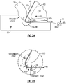
Figure 1 illustrates an example process for machining. -
Figure 2A illustrates an example tool-metal alloy workpiece cross-section during the process ofFigure 1 . -
Figure 2B illustrates a magnified view in the vicinity of a cutting tip of a tool inFigure 2A . -
Figure 1 illustrates a machining process flow diagram 20, andFigures 2A and 2B illustrate a tool-metalalloy workpiece cross-section 50 during theprocess 20. As will be described, theprocess 20 utilizes ananofluid 40 to, among other purposes, remove heat from the vicinity of cut. In general, referring to bothFigures 1 and2 , theprocess 20 includes the provision of a cutting tool 52 atstep 22, bringing the cutting tool 52 into contact with theworkpiece 50 atstep 24, and introducing thenanofluid 40 into the vicinity of the cutting to remove heat and to customize surface finish atstep 26. - As shown in
Figures 2A and 2B , the cutting tool 52 includes arake face 52a and aflank face 52b that meet at acutting tip 52c. Therake face 52a is the leading edge surface of the tool 52 that initially contacts thechips 54. Theflank face 52b is the adjacent trailing edge surface. During theprocess 20, thecutting tip 52c penetrates into theworkpiece 50 to form achip 54. In this regard, either theworkpiece 50, the cutting tool 52, or both may be moving or rotating (relative to each other) to produce the penetration. In the example shown, the relative movement of the cutting tool 52 is represented at arrow R. - As is generally known for cutting processes, this type of cutting produces a primary deformation (shear) zone ahead of the
chip 54, a secondary deformation (shear) zone at the rake face of the tool and the back surface of thechip 54, and a tertiary deformation zone in anew surface 50a behind the toolclearance flank face 52b. Most typically, the primary deformation zone is in elasto-plastic deformation, the secondary deformation zone is in plastic deformation, and the tertiary deformation zone is in elastic deformation. Each deformation produces heat which, if not adequately removed, may result in undesired phase transformations, work hardening, and surface roughening of theworkpiece 50 and ductile deformation and thermal fatigue of the cutting tool leading to tool wear 52, all due to large uneven temperature distributions. The heat generation and removal can be controlled to some extent by limiting cutting speed; however, the use of thenanofluid 40 removes heat and may facilitate enhancement for a wider range of tool or workpiece materials and/or a wider range of machining conditions, such as more aggressive cutting parameters or higher cutting rates, as well as enabling longer tool life. - The
nanofluid 40 includes a base carrier fluid. The base carrier fluid is a cryo-liquid (represented at 40a), such as liquid nitrogen, liquid carbon dioxide, liquid argon, liquid helium, or mixtures thereof. The cryo-liquid 40a is mixed with nanoparticles (represented at 40b) that have a maximum size of approximately 0.1 nanometers to approximately 100 nanometers. Most typically, thenanoparticles 40b will be less than or equal to 20 nanometers in size, to enhance dispersion by Brownian motion. The mixture (dispersion) can be prepared by physical mixing, for example by using an ultrasonic transducer. Thenanoparticle 40b composition and size can be selected to minimize the dispersion Péclet number and settling according to Stoke's Law, in order to optimize cryogenic dispersion stability via Brownian motion. - The
nanoparticles 40b may be selected from metal carbides, metal nitrides including the hexagonal form of boron nitride, metal borides, and their mixed phases; lamellar compounds, such as but not limited to metal (e.g., Zn, W, Mo) sulfides and borates; alkali (e.g., Na, K) or alkaline earth (e.g., Mg) silicates and their hydroxides (e.g., talc); carbon allotropes, such as but not limited to graphene (oxide), ultradispersed nano-crystalline diamond, DLC, graphite, spheroidal carbons, including fullerenes and carbon nanorods; silver or other soft metals with low vapor pressures (e.g., indium, copper, tin); and fluorides such as but not limited to calcium fluoride and rare earth fluorides (e.g., CeF3). Most typically, thenanoparticles 40b will be spherical, ellipsoidal, or tube/rod in shape. - The composition of the
nanoparticles 40b can be selected in cooperation with the type of metal alloy of theworkpiece 50 and/or the composition of the cutting tool 52. For example, the metal alloy of theworkpiece 50 is iron, steel, hardened steel, nickel alloy, or titanium alloy. The cutting tool 52 may be formed of a carbide tool, tool steel, tungsten carbides, nitrides, borides, or their mixed phases (e.g., cubic boron nitride, cermets, such as ceramic/metal composites, or polycrystalline diamond). The tool can be uncoated, or coated with TiN, TiCN, TiAlN, AlTiN, AlCrN, diamond-like carbon (DLC), or molybdenum disulphide (MoS2), for example. As will be appreciated, the surfaces of theworkpiece 50 and the cutting tool 52 may also be passivated with native oxides that are polar or hydrophilic in character. For titanium alloy it is always preferable to use uncoated carbide tools. Here, metal carbide nanoparticles may be used in the nanofluid to chemically interact with the freshly generated surface on the workpiece, in order to supplant detrimental workpiece reactions with the carbide tool surface. However, for hardened steel workpieces, ceramic based and CBN tools are more recommended. Nanofluids with metal boride or metal carbide nanoparticles are compatible with these couples, and may interact to provide further strengthening of the steel surface and prevent tool wear. Thus, using nanofluid for cooling the vicinity of cutting can improve the performance of specific tool-workpiece configurations and further provide enhancement of surface properties. - The nanofluid may be introduced into the vicinity of the penetration of the cutting tool 52 into the
workpiece 50 by external introduction, internal introduction, or both. The terms "external" and "internal" refer to the nanofluid 40 being introduced, respectively, external to or internal to the cutting tool 52. In external introduction, the nanofluid 40 is introduced by, for example, using a specially designed nozzle for spraying the nanofluid 40 toward the cuttingtip 52c. For instance, the nanofluid 40 can be sprayed ahead of the cutting tool 52 adjacent to therake face 52a, sprayed along theflank face 52b, or both. Most typically, the nanofluid 40 will be sprayed using one or more nozzles, similar to nozzles that are already known for spraying pure cryogenic or non-cryogenic fluids. In internal introduction, the nanofluid 40 is circulated through a passage (represented at 60) in the cutting tool 52. In this case, the nanofluid 40 may not contact the actual cutting interface with theworkpiece 50. However, the nanofluid 40 could additionally be externally introduced or be discharged from thepassage 60 external to the cutting tool 52 directly into the cutting interface. - The nanofluid 40 includes, by weight, up to 10% of the
nanoparticles 40b. Most typically, the nanofluid 40 will include, by weight, from approximately 0.1% to approximately 2% of thenanoparticles 40b. In further examples, the nanofluid 40 may include only the cryo-liquid 40a and thenanoparticles 40b. As used herein, the term "approximately" refers measuring error in the next significant digit (e.g., for 0.1, error in the hundredths decimal). - The nanofluid 40 may further include a surfactant agent (coupling agent) to facilitate dispersion in the cryo-liquid 40a. For instance, the
nanoparticle 40b concentration in the nanofluid 40, morphology, aspect ratio, and surface functionality (modified, if necessary, with surfactants or coupling agents) are optimized to prevent their aggregation, and also to tailor nanofluid-surface interactions for the workpiece contact topology. For example, the surfactant agent is an amphiphilic compound that contains a polar functional group with one or more heteroatoms (besides carbon or hydrogen) at the end of long molecular tails (often called boundary additives in lubricant formulations). The endgroups can either physisorb (weak, associative bonding) or chemisorb (strong, covalent or ionic bonding) on the surfaces of thenanoparticles 40b. The strength of the bonding interaction depends on the endgroup, and the difference in the acid-base character of the endgroup and the nanoparticle surface. Most typically, the surfactant is selected in accordance with the chemistry of thenanoparticles 40b such that the bonding interactions are reversible, to enable their desorption and readsorption on mechanical contact surfaces at higher temperatures. Example endgroups may include, but are not limited to, anionic groups (polar functional groups, negatively charged), such as carboxylates (e.g., including fatty acids), sulfates, sulphonates, phosphates, phosphonates, and phosphites; nonionic groups (polar functional groups that have non-bonding electron pairs), such as alcohols, alcohol ethers, ethers, and esters; and cationic groups (polar functional group positively charged), such as amines. - In further examples, the endgroups have molecular tails to enhance nanoparticle dispersion by steric stabilization. For example, the molecular tails have atomic backbones that are 15-30 atoms in length, to enable their extension and flexibility in solution with minimum entanglement. The backbones can be formed from, for example, hydrocarbons (including alkyl, straight, or branched saturated; olefinic or unsaturated; or aromatic), fluorocarbons, or siloxanes.
- In another example, the
nanoparticles 40b are frozen in the cryo-liquid 40a but are non-solid at 20 °C and an absolute pressure of 1 atm. For example, thenanoparticles 40b are frozen particles formed by freezing droplets of ambient temperature liquids (e.g., low molecular weight, alcohols, glycols, fatty acids, hydrocarbons). In addition to serving the functions described above, thefrozen nanoparticles 40b may serve to polish the surface of theworkpiece 50 upon melting. In addition, trapped gas bubbles (e.g., air, helium, argon) may be injected into the cryo-liquid 40a and used to tailor surface finish by cavitation effects. - The
nanoparticles 40b serve to enhance the performance of the nanofluid 40 in theprocess 20. For example, although the large temperature differential of the cryo-liquid 40a is effective for removing heat, thenanoparticles 40b further enhance heat removal by i) enabling infiltration into the chip-tool interface where the highest temperatures are generated, ii) providing increased nanofluid thermal conductivity compared to the base cryo-liquid, iii) providing nanoconvection effects from thenanoparticles 40b, and iv) enhancing wetting of the nanoparticle-entrained cryo-liquid into the cutting region to locally reduce thermal gradients. - The
nanoparticles 40b also reduce friction in the cutting region. This is achieved by increasing the capacity for a hydrodynamic film of the nanofluid 40 to maintain a separation (designated at "S1") and bear loads without collapsing, thereby reducing the coefficient of friction, reducing heat generation, reducing grinding forces, reducing ratio of workpiece removal-tool wear, enhancing chip ejection, and improving surface finish. As an example, the nanofluid can maintain a separation S1 of less than approximately 0.1 micrometers at thecutting tip 52c. In this regard, the nanofluid 40 can be used on selected surfaces of a component, such as a nickel component, to tailor the quality of the surface finish of those surfaces to make the surfaces smoother or rougher or harder or softer. Reductions in the coefficient of friction may lead to a reduction in the radial forces which will improve tool life, surface integrity and reduced workpiece deformation. The use of the nanofluid 40 may also increase productivity by at least a factor of two due to the increase in cutting speed (nanofluid reductions in the interfacial temperature allow for increasing the speed by a factor of two, in addition to increases in feed rate). By developing a specially designed nozzle, it is possible to utilize multiple types of nanoparticle materials, and vary their sizes and distributions. The correct material and size can be released during machining at different rates and configurations based on the design requirements for the functionally graded surface. - The
nanoparticles 40b can further be used to form a coating on theworkpiece 50 and/or cutting tool 52. For example, thenanoparticles 40b may be reactive under high loads due to their high surface per unit weight compared to larger macroparticles, which controls their stability and reactivity. The surfaces of thenanoparticles 40b, particularly those containing sulfur or boron, may have unsaturated chemical valences, which may drive reactions under high loads. In particular, such high loads can be deliberately created in the vicinity of the tertiary zone, where there may be a separation of less than approximately 0.05 micrometers (designated at "S2") between the cutting tool 52 and newly exposed surface of the workpiece 50 (designated at 56). In this way, they may function like lubricant extreme pressure/anti-wear additives, which typically contain sulfur, phosphorus, or chlorine, that react with the newly createdsurface 56 to form protective coatings to prevent tool-workpiece contact under high loads and/or high temperatures. Contact loads can increase up to the load equivalent of the workpiece hardness. Under such high contact loads, thenanoparticles 40b may deform and "stick" or adhere to the newly createdsurface 56 of theworkpiece 50 and/or cutting tool 52, where they react with each other to form a localized and very thin coating layer that may serve to protect or heal surface defects in theunderlying workpiece 50 or cutting tool 52. The nanofluid particles can be added deliberately efficiently and effectively generate functionally graded surface condition for certain design requirements. - Although a combination of features is shown in the illustrated examples, not all of them need to be combined to realize the benefits of various embodiments of this disclosure. In other words, a system designed according to an embodiment of this disclosure will not necessarily include all of the features shown in any one of the Figures or all of the portions schematically shown in the Figures. Moreover, selected features of one example embodiment may be combined with selected features of other example embodiments.
- The preceding description is exemplary rather than limiting in nature. Variations and modifications to the disclosed examples may become apparent to those skilled in the art that do not necessarily depart from this disclosure. The scope of legal protection given to this disclosure can only be determined by studying the following claims.
Claims (14)
- A machining process (20) comprising:providing a cutting tool (52) having a rake face (52a) and a flank face (52b);bringing the cutting tool (52) into contact with a metal alloy workpiece (50) to form a chip (54) by penetrating the cutting tool (52) into the workpiece (50); andintroducing a nanofluid (40) into a vicinity of the penetration to remove heat, the nanofluid including a mixture of:a cryo-liquid (40a), andnanoparticles (40b) having a maximum size of approximately 0.1 nanometers to approximately 100 nanometers.
- The machining process (20) as recited in claim 1, including using the nanoparticles (40b) of the nanofluid (40) that reacts to form a functional protective coating on at least one of cutting tool (52) or the workpiece (50).
- The machining process (24) as recited in claim 1 or 2, wherein the nanofluid (40) is introduced into the vicinity of the penetration externally of the cutting by directing the nanofluid (40) toward the rake face (52a), the flank face (52b), or both the rake face (52a) and the flank face (52b).
- The machining process (20) as recited in claim 1 or 2, wherein the nanofluid (40) is introduced into the vicinity of the penetration internally to the cutting by circulating the nanofluid (40) within the cutting tool (52).
- A fluid (40) for aiding in a machining process (20), comprising nanofluid (40) including a mixture of:a cryo-liquid (40a), andnanoparticles (40b) having a maximum size of approximately 0.1 nanometers to approximately 100 nanometers.
- The fluid (40) or machining process (20) of any preceding claim, wherein the nanofluid (40) contains, by weight, up to 10% nanoparticles (40b).
- The fluid (40) or machining process (20) of any preceding claim, wherein the nanofluid (40) contains, by weight, from approximately 0.1% to approximately 2% nanoparticles.
- The fluid (40) or machining process (20) as recited in any preceding claim, wherein the nanoparticles (40b) are selected from the group consisting of metal carbides, metal nitrides, hexagonal form of boron nitride, metal borides, and combinations thereof.
- The fluid (40) or machining process (20) as recited in any of claims 1 to 7, wherein the nanoparticles (40b) are selected from the group consisting of carbon allotropes.
- The fluid (40) or machining process (20) as recited in any of claims 1 to 7, wherein the nanoparticles (40b) are selected from the group consisting of metal sulfides, metal borates, and combinations thereof.
- The fluid (40) or machining process (20) as recited in any of claims 1 to 7, wherein the nanoparticles (40b) are selected from the group consisting of metal silicates, metal fluorides, and combinations thereof.
- The fluid (40) or machining process (20) of any of claims 1 to 7, wherein the nanoparticles (40b) are metals selected from the group consisting of silver, indium, copper, tin, and combinations thereof.
- The fluid (40) or machining process (20) of any preceding claim, wherein the nanofluid (40) includes a surfactant agent coupled to surfaces of the nanoparticles, the surfactant agent is selected from the group consisting of amphiphilic compounds that contain a polar functional group and a heteroatom, and the surfactant agent has an atomic backbone that is from 15 to 30 atoms in length.
- The fluid (40) or machining process (20) of any preceding claim, wherein the nanoparticles (40b) are solid in the cryo-liquid (40a) and are non-solid at 20 °C and an absolute pressure of 1 atm.
Applications Claiming Priority (1)
| Application Number | Priority Date | Filing Date | Title |
|---|---|---|---|
| US15/483,115 US10632584B2 (en) | 2017-04-10 | 2017-04-10 | Cryogenic machining process using nanofluid |
Publications (2)
| Publication Number | Publication Date |
|---|---|
| EP3388193A1 true EP3388193A1 (en) | 2018-10-17 |
| EP3388193B1 EP3388193B1 (en) | 2022-06-01 |
Family
ID=62046644
Family Applications (1)
| Application Number | Title | Priority Date | Filing Date |
|---|---|---|---|
| EP18166410.3A Active EP3388193B1 (en) | 2017-04-10 | 2018-04-09 | Cryogenic machining process using nanofluid |
Country Status (2)
| Country | Link |
|---|---|
| US (1) | US10632584B2 (en) |
| EP (1) | EP3388193B1 (en) |
Cited By (1)
| Publication number | Priority date | Publication date | Assignee | Title |
|---|---|---|---|---|
| TWI734001B (en) * | 2017-03-29 | 2021-07-21 | 印度商皮埃企業有限公司 | A process for preparing alkylene bis-dithiophosphates |
Families Citing this family (1)
| Publication number | Priority date | Publication date | Assignee | Title |
|---|---|---|---|---|
| EP3538305B1 (en) * | 2016-11-08 | 2024-07-03 | Sandvik Intellectual Property AB | Method of machining ti, ti-alloys and ni-based alloys |
Citations (2)
| Publication number | Priority date | Publication date | Assignee | Title |
|---|---|---|---|---|
| WO2006065869A2 (en) * | 2004-12-13 | 2006-06-22 | Cool Clean Technologies, Inc. | Cryogenic fluid composition |
| WO2007044923A2 (en) * | 2005-10-13 | 2007-04-19 | Cool Clean Technologies, Inc. | Nozzle device and method for forming cryogenic composite fluid spray |
Family Cites Families (5)
| Publication number | Priority date | Publication date | Assignee | Title |
|---|---|---|---|---|
| AU3323695A (en) * | 1994-08-09 | 1996-03-07 | Edison Materials Technology Center, The | Cryogenic machining |
| US7348298B2 (en) * | 2002-05-30 | 2008-03-25 | Ashland Licensing And Intellectual Property, Llc | Enhancing thermal conductivity of fluids with graphite nanoparticles and carbon nanotube |
| US7871533B1 (en) * | 2006-01-12 | 2011-01-18 | South Dakota School Of Mines And Technology | Carbon nanoparticle-containing nanofluid |
| US20070215253A1 (en) | 2006-03-17 | 2007-09-20 | Dasch Jean M | Dissipating friction and heat during machining |
| US8839497B2 (en) | 2009-02-19 | 2014-09-23 | Purdue Research Foundation | Machining apparatus and process |
-
2017
- 2017-04-10 US US15/483,115 patent/US10632584B2/en active Active
-
2018
- 2018-04-09 EP EP18166410.3A patent/EP3388193B1/en active Active
Patent Citations (2)
| Publication number | Priority date | Publication date | Assignee | Title |
|---|---|---|---|---|
| WO2006065869A2 (en) * | 2004-12-13 | 2006-06-22 | Cool Clean Technologies, Inc. | Cryogenic fluid composition |
| WO2007044923A2 (en) * | 2005-10-13 | 2007-04-19 | Cool Clean Technologies, Inc. | Nozzle device and method for forming cryogenic composite fluid spray |
Cited By (1)
| Publication number | Priority date | Publication date | Assignee | Title |
|---|---|---|---|---|
| TWI734001B (en) * | 2017-03-29 | 2021-07-21 | 印度商皮埃企業有限公司 | A process for preparing alkylene bis-dithiophosphates |
Also Published As
| Publication number | Publication date |
|---|---|
| US20180290254A1 (en) | 2018-10-11 |
| EP3388193B1 (en) | 2022-06-01 |
| US10632584B2 (en) | 2020-04-28 |
Similar Documents
| Publication | Publication Date | Title |
|---|---|---|
| Park et al. | Milling of titanium alloy with cryogenic cooling and minimum quantity lubrication (MQL) | |
| Ezugwu et al. | Machining of nickel-base, Inconel 718, alloy with ceramic tools under finishing conditions with various coolant supply pressures | |
| Diniz et al. | Tool wear mechanisms in the machining of steels and stainless steels | |
| Gupta et al. | Potential use of cryogenic cooling for improving the tribological and tool wear characteristics while machining aluminum alloys | |
| Sahoo et al. | Dry, MQL, and nanofluid MQL machining of Ti–6Al–4V using uncoated WC–Co insert: application of jatropha oil as base cutting fluid and graphene nanoplatelets as additives | |
| Bonfá et al. | Evaluation of tool life and workpiece surface roughness in turning of AISI D6 hardened steel using PCBN tools and minimum quantity of lubricant (MQL) applied at different directions | |
| Tiwari et al. | A review on minimum quantity lubrication in machining of different alloys and superalloys using nanofluids | |
| de Souza Ruzzi et al. | Study on grinding of inconel 625 and 718 alloys with cutting fluid enriched with multilayer graphene platelets | |
| Duan et al. | Effects of cooling and lubrication conditions on tool wear in turning of Al/SiCp composite | |
| EP3388193B1 (en) | Cryogenic machining process using nanofluid | |
| Mia et al. | Advanced cooling-lubrication technologies in metal machining | |
| Qin et al. | Feasibility study on the minimum quantity lubrication in high-speed helical milling of Ti-6Al-4V | |
| Bayraktar | Cryogenic cooling-based sustainable machining | |
| Maurya et al. | Ionic liquids as a potential sustainable green lubricant for machining in the era of industry 4.0 | |
| Liew et al. | Comparison between carbon nanofiber (CNF) nanofluid with deionized water on tool life and surface roughness in turning of D2 steel | |
| Zainol et al. | The effect of portable MQL applicator onto carbide insert during turning Inconel 718 | |
| Kinalkar et al. | A review on various cooling system employed in grinding | |
| CN108436607A (en) | A kind of processing method of bulk metal ceramics milling cutter | |
| Kumar et al. | Nanofluids Application for Cutting Fluids | |
| Eltaggaz et al. | The effect of nanoparticle concentration on Mql performance when machining Ti-6Al-4V titanium alloy | |
| Dhar et al. | Effects of minimum quantity lubrication (MQL) by vegetable oil-based cutting fluid on machinability of AISI 9310 steel | |
| Banerjee et al. | A review on localised and multi-point aerosol application in minimum quantity lubrication machining | |
| Singh et al. | An Improvised Method of Machinability Evaluation with Predictive Temperature Model for Inconel 625: A Holistic Machinist’s Perspective | |
| Sankar et al. | Machining of metal matrix composites with minimum quantity cutting fluid and flood cooling | |
| Chan et al. | Use of nano-droplet-enriched cutting fluid (NDCF) in ultra-precision machining |
Legal Events
| Date | Code | Title | Description |
|---|---|---|---|
| PUAI | Public reference made under article 153(3) epc to a published international application that has entered the european phase |
Free format text: ORIGINAL CODE: 0009012 |
|
| STAA | Information on the status of an ep patent application or granted ep patent |
Free format text: STATUS: THE APPLICATION HAS BEEN PUBLISHED |
|
| AK | Designated contracting states |
Kind code of ref document: A1 Designated state(s): AL AT BE BG CH CY CZ DE DK EE ES FI FR GB GR HR HU IE IS IT LI LT LU LV MC MK MT NL NO PL PT RO RS SE SI SK SM TR |
|
| AX | Request for extension of the european patent |
Extension state: BA ME |
|
| STAA | Information on the status of an ep patent application or granted ep patent |
Free format text: STATUS: REQUEST FOR EXAMINATION WAS MADE |
|
| 17P | Request for examination filed |
Effective date: 20190417 |
|
| RBV | Designated contracting states (corrected) |
Designated state(s): AL AT BE BG CH CY CZ DE DK EE ES FI FR GB GR HR HU IE IS IT LI LT LU LV MC MK MT NL NO PL PT RO RS SE SI SK SM TR |
|
| RAP1 | Party data changed (applicant data changed or rights of an application transferred) |
Owner name: RAYTHEON TECHNOLOGIES CORPORATION |
|
| GRAP | Despatch of communication of intention to grant a patent |
Free format text: ORIGINAL CODE: EPIDOSNIGR1 |
|
| STAA | Information on the status of an ep patent application or granted ep patent |
Free format text: STATUS: GRANT OF PATENT IS INTENDED |
|
| RIC1 | Information provided on ipc code assigned before grant |
Ipc: C10N 40/22 20060101ALI20210917BHEP Ipc: C10N 20/06 20060101ALI20210917BHEP Ipc: C10M 171/06 20060101ALI20210917BHEP Ipc: C10M 125/00 20060101ALI20210917BHEP Ipc: B23Q 11/10 20060101AFI20210917BHEP |
|
| INTG | Intention to grant announced |
Effective date: 20211019 |
|
| GRAS | Grant fee paid |
Free format text: ORIGINAL CODE: EPIDOSNIGR3 |
|
| GRAA | (expected) grant |
Free format text: ORIGINAL CODE: 0009210 |
|
| STAA | Information on the status of an ep patent application or granted ep patent |
Free format text: STATUS: THE PATENT HAS BEEN GRANTED |
|
| AK | Designated contracting states |
Kind code of ref document: B1 Designated state(s): AL AT BE BG CH CY CZ DE DK EE ES FI FR GB GR HR HU IE IS IT LI LT LU LV MC MK MT NL NO PL PT RO RS SE SI SK SM TR |
|
| REG | Reference to a national code |
Ref country code: GB Ref legal event code: FG4D |
|
| REG | Reference to a national code |
Ref country code: AT Ref legal event code: REF Ref document number: 1495042 Country of ref document: AT Kind code of ref document: T Effective date: 20220615 Ref country code: CH Ref legal event code: EP |
|
| REG | Reference to a national code |
Ref country code: IE Ref legal event code: FG4D |
|
| REG | Reference to a national code |
Ref country code: DE Ref legal event code: R096 Ref document number: 602018036096 Country of ref document: DE |
|
| REG | Reference to a national code |
Ref country code: LT Ref legal event code: MG9D |
|
| REG | Reference to a national code |
Ref country code: NL Ref legal event code: MP Effective date: 20220601 |
|
| PG25 | Lapsed in a contracting state [announced via postgrant information from national office to epo] |
Ref country code: SE Free format text: LAPSE BECAUSE OF FAILURE TO SUBMIT A TRANSLATION OF THE DESCRIPTION OR TO PAY THE FEE WITHIN THE PRESCRIBED TIME-LIMIT Effective date: 20220601 Ref country code: NO Free format text: LAPSE BECAUSE OF FAILURE TO SUBMIT A TRANSLATION OF THE DESCRIPTION OR TO PAY THE FEE WITHIN THE PRESCRIBED TIME-LIMIT Effective date: 20220901 Ref country code: LT Free format text: LAPSE BECAUSE OF FAILURE TO SUBMIT A TRANSLATION OF THE DESCRIPTION OR TO PAY THE FEE WITHIN THE PRESCRIBED TIME-LIMIT Effective date: 20220601 Ref country code: HR Free format text: LAPSE BECAUSE OF FAILURE TO SUBMIT A TRANSLATION OF THE DESCRIPTION OR TO PAY THE FEE WITHIN THE PRESCRIBED TIME-LIMIT Effective date: 20220601 Ref country code: GR Free format text: LAPSE BECAUSE OF FAILURE TO SUBMIT A TRANSLATION OF THE DESCRIPTION OR TO PAY THE FEE WITHIN THE PRESCRIBED TIME-LIMIT Effective date: 20220902 Ref country code: FI Free format text: LAPSE BECAUSE OF FAILURE TO SUBMIT A TRANSLATION OF THE DESCRIPTION OR TO PAY THE FEE WITHIN THE PRESCRIBED TIME-LIMIT Effective date: 20220601 Ref country code: ES Free format text: LAPSE BECAUSE OF FAILURE TO SUBMIT A TRANSLATION OF THE DESCRIPTION OR TO PAY THE FEE WITHIN THE PRESCRIBED TIME-LIMIT Effective date: 20220601 Ref country code: BG Free format text: LAPSE BECAUSE OF FAILURE TO SUBMIT A TRANSLATION OF THE DESCRIPTION OR TO PAY THE FEE WITHIN THE PRESCRIBED TIME-LIMIT Effective date: 20220901 |
|
| REG | Reference to a national code |
Ref country code: AT Ref legal event code: MK05 Ref document number: 1495042 Country of ref document: AT Kind code of ref document: T Effective date: 20220601 |
|
| PG25 | Lapsed in a contracting state [announced via postgrant information from national office to epo] |
Ref country code: RS Free format text: LAPSE BECAUSE OF FAILURE TO SUBMIT A TRANSLATION OF THE DESCRIPTION OR TO PAY THE FEE WITHIN THE PRESCRIBED TIME-LIMIT Effective date: 20220601 Ref country code: PL Free format text: LAPSE BECAUSE OF FAILURE TO SUBMIT A TRANSLATION OF THE DESCRIPTION OR TO PAY THE FEE WITHIN THE PRESCRIBED TIME-LIMIT Effective date: 20220601 Ref country code: LV Free format text: LAPSE BECAUSE OF FAILURE TO SUBMIT A TRANSLATION OF THE DESCRIPTION OR TO PAY THE FEE WITHIN THE PRESCRIBED TIME-LIMIT Effective date: 20220601 |
|
| PG25 | Lapsed in a contracting state [announced via postgrant information from national office to epo] |
Ref country code: NL Free format text: LAPSE BECAUSE OF FAILURE TO SUBMIT A TRANSLATION OF THE DESCRIPTION OR TO PAY THE FEE WITHIN THE PRESCRIBED TIME-LIMIT Effective date: 20220601 |
|
| PG25 | Lapsed in a contracting state [announced via postgrant information from national office to epo] |
Ref country code: SM Free format text: LAPSE BECAUSE OF FAILURE TO SUBMIT A TRANSLATION OF THE DESCRIPTION OR TO PAY THE FEE WITHIN THE PRESCRIBED TIME-LIMIT Effective date: 20220601 Ref country code: SK Free format text: LAPSE BECAUSE OF FAILURE TO SUBMIT A TRANSLATION OF THE DESCRIPTION OR TO PAY THE FEE WITHIN THE PRESCRIBED TIME-LIMIT Effective date: 20220601 Ref country code: RO Free format text: LAPSE BECAUSE OF FAILURE TO SUBMIT A TRANSLATION OF THE DESCRIPTION OR TO PAY THE FEE WITHIN THE PRESCRIBED TIME-LIMIT Effective date: 20220601 Ref country code: PT Free format text: LAPSE BECAUSE OF FAILURE TO SUBMIT A TRANSLATION OF THE DESCRIPTION OR TO PAY THE FEE WITHIN THE PRESCRIBED TIME-LIMIT Effective date: 20221003 Ref country code: EE Free format text: LAPSE BECAUSE OF FAILURE TO SUBMIT A TRANSLATION OF THE DESCRIPTION OR TO PAY THE FEE WITHIN THE PRESCRIBED TIME-LIMIT Effective date: 20220601 Ref country code: CZ Free format text: LAPSE BECAUSE OF FAILURE TO SUBMIT A TRANSLATION OF THE DESCRIPTION OR TO PAY THE FEE WITHIN THE PRESCRIBED TIME-LIMIT Effective date: 20220601 Ref country code: AT Free format text: LAPSE BECAUSE OF FAILURE TO SUBMIT A TRANSLATION OF THE DESCRIPTION OR TO PAY THE FEE WITHIN THE PRESCRIBED TIME-LIMIT Effective date: 20220601 |
|
| PG25 | Lapsed in a contracting state [announced via postgrant information from national office to epo] |
Ref country code: IS Free format text: LAPSE BECAUSE OF FAILURE TO SUBMIT A TRANSLATION OF THE DESCRIPTION OR TO PAY THE FEE WITHIN THE PRESCRIBED TIME-LIMIT Effective date: 20221001 |
|
| REG | Reference to a national code |
Ref country code: DE Ref legal event code: R097 Ref document number: 602018036096 Country of ref document: DE |
|
| PG25 | Lapsed in a contracting state [announced via postgrant information from national office to epo] |
Ref country code: AL Free format text: LAPSE BECAUSE OF FAILURE TO SUBMIT A TRANSLATION OF THE DESCRIPTION OR TO PAY THE FEE WITHIN THE PRESCRIBED TIME-LIMIT Effective date: 20220601 |
|
| PLBE | No opposition filed within time limit |
Free format text: ORIGINAL CODE: 0009261 |
|
| STAA | Information on the status of an ep patent application or granted ep patent |
Free format text: STATUS: NO OPPOSITION FILED WITHIN TIME LIMIT |
|
| PG25 | Lapsed in a contracting state [announced via postgrant information from national office to epo] |
Ref country code: DK Free format text: LAPSE BECAUSE OF FAILURE TO SUBMIT A TRANSLATION OF THE DESCRIPTION OR TO PAY THE FEE WITHIN THE PRESCRIBED TIME-LIMIT Effective date: 20220601 |
|
| 26N | No opposition filed |
Effective date: 20230302 |
|
| PG25 | Lapsed in a contracting state [announced via postgrant information from national office to epo] |
Ref country code: SI Free format text: LAPSE BECAUSE OF FAILURE TO SUBMIT A TRANSLATION OF THE DESCRIPTION OR TO PAY THE FEE WITHIN THE PRESCRIBED TIME-LIMIT Effective date: 20220601 |
|
| P01 | Opt-out of the competence of the unified patent court (upc) registered |
Effective date: 20230521 |
|
| REG | Reference to a national code |
Ref country code: CH Ref legal event code: PL |
|
| PG25 | Lapsed in a contracting state [announced via postgrant information from national office to epo] |
Ref country code: LU Free format text: LAPSE BECAUSE OF NON-PAYMENT OF DUE FEES Effective date: 20230409 |
|
| REG | Reference to a national code |
Ref country code: BE Ref legal event code: MM Effective date: 20230430 |
|
| PG25 | Lapsed in a contracting state [announced via postgrant information from national office to epo] |
Ref country code: MC Free format text: LAPSE BECAUSE OF FAILURE TO SUBMIT A TRANSLATION OF THE DESCRIPTION OR TO PAY THE FEE WITHIN THE PRESCRIBED TIME-LIMIT Effective date: 20220601 |
|
| PG25 | Lapsed in a contracting state [announced via postgrant information from national office to epo] |
Ref country code: MC Free format text: LAPSE BECAUSE OF FAILURE TO SUBMIT A TRANSLATION OF THE DESCRIPTION OR TO PAY THE FEE WITHIN THE PRESCRIBED TIME-LIMIT Effective date: 20220601 Ref country code: LI Free format text: LAPSE BECAUSE OF NON-PAYMENT OF DUE FEES Effective date: 20230430 Ref country code: IT Free format text: LAPSE BECAUSE OF FAILURE TO SUBMIT A TRANSLATION OF THE DESCRIPTION OR TO PAY THE FEE WITHIN THE PRESCRIBED TIME-LIMIT Effective date: 20220601 Ref country code: CH Free format text: LAPSE BECAUSE OF NON-PAYMENT OF DUE FEES Effective date: 20230430 |
|
| REG | Reference to a national code |
Ref country code: IE Ref legal event code: MM4A |
|
| PG25 | Lapsed in a contracting state [announced via postgrant information from national office to epo] |
Ref country code: BE Free format text: LAPSE BECAUSE OF NON-PAYMENT OF DUE FEES Effective date: 20230430 |
|
| PG25 | Lapsed in a contracting state [announced via postgrant information from national office to epo] |
Ref country code: IE Free format text: LAPSE BECAUSE OF NON-PAYMENT OF DUE FEES Effective date: 20230409 |
|
| PG25 | Lapsed in a contracting state [announced via postgrant information from national office to epo] |
Ref country code: IE Free format text: LAPSE BECAUSE OF NON-PAYMENT OF DUE FEES Effective date: 20230409 |
|
| PG25 | Lapsed in a contracting state [announced via postgrant information from national office to epo] |
Ref country code: BG Free format text: LAPSE BECAUSE OF FAILURE TO SUBMIT A TRANSLATION OF THE DESCRIPTION OR TO PAY THE FEE WITHIN THE PRESCRIBED TIME-LIMIT Effective date: 20220601 |
|
| PG25 | Lapsed in a contracting state [announced via postgrant information from national office to epo] |
Ref country code: BG Free format text: LAPSE BECAUSE OF FAILURE TO SUBMIT A TRANSLATION OF THE DESCRIPTION OR TO PAY THE FEE WITHIN THE PRESCRIBED TIME-LIMIT Effective date: 20220601 |
|
| PGFP | Annual fee paid to national office [announced via postgrant information from national office to epo] |
Ref country code: DE Payment date: 20250319 Year of fee payment: 8 |
|
| PG25 | Lapsed in a contracting state [announced via postgrant information from national office to epo] |
Ref country code: CY Free format text: LAPSE BECAUSE OF FAILURE TO SUBMIT A TRANSLATION OF THE DESCRIPTION OR TO PAY THE FEE WITHIN THE PRESCRIBED TIME-LIMIT; INVALID AB INITIO Effective date: 20180409 |
|
| PG25 | Lapsed in a contracting state [announced via postgrant information from national office to epo] |
Ref country code: HU Free format text: LAPSE BECAUSE OF FAILURE TO SUBMIT A TRANSLATION OF THE DESCRIPTION OR TO PAY THE FEE WITHIN THE PRESCRIBED TIME-LIMIT; INVALID AB INITIO Effective date: 20180409 |
|
| REG | Reference to a national code |
Ref country code: DE Ref legal event code: R081 Ref document number: 602018036096 Country of ref document: DE Owner name: RTX CORPORATION (N.D.GES.D. STAATES DELAWARE),, US Free format text: FORMER OWNER: RAYTHEON TECHNOLOGIES CORPORATION, FARMINGTON, CT, US |
|
| PG25 | Lapsed in a contracting state [announced via postgrant information from national office to epo] |
Ref country code: TR Free format text: LAPSE BECAUSE OF FAILURE TO SUBMIT A TRANSLATION OF THE DESCRIPTION OR TO PAY THE FEE WITHIN THE PRESCRIBED TIME-LIMIT Effective date: 20220601 |
|
| PGFP | Annual fee paid to national office [announced via postgrant information from national office to epo] |
Ref country code: GB Payment date: 20260319 Year of fee payment: 9 |
|
| PGFP | Annual fee paid to national office [announced via postgrant information from national office to epo] |
Ref country code: FR Payment date: 20260320 Year of fee payment: 9 |