EP3388110A1 - Coil arrangement - Google Patents
Coil arrangement Download PDFInfo
- Publication number
- EP3388110A1 EP3388110A1 EP18166728.8A EP18166728A EP3388110A1 EP 3388110 A1 EP3388110 A1 EP 3388110A1 EP 18166728 A EP18166728 A EP 18166728A EP 3388110 A1 EP3388110 A1 EP 3388110A1
- Authority
- EP
- European Patent Office
- Prior art keywords
- patient
- guide track
- support stand
- patient bed
- bed
- Prior art date
- Legal status (The legal status is an assumption and is not a legal conclusion. Google has not performed a legal analysis and makes no representation as to the accuracy of the status listed.)
- Granted
Links
Images



Classifications
-
- A—HUMAN NECESSITIES
- A61—MEDICAL OR VETERINARY SCIENCE; HYGIENE
- A61N—ELECTROTHERAPY; MAGNETOTHERAPY; RADIATION THERAPY; ULTRASOUND THERAPY
- A61N5/00—Radiation therapy
- A61N5/10—X-ray therapy; Gamma-ray therapy; Particle-irradiation therapy
- A61N5/103—Treatment planning systems
- A61N5/1039—Treatment planning systems using functional images, e.g. PET or MRI
-
- A—HUMAN NECESSITIES
- A61—MEDICAL OR VETERINARY SCIENCE; HYGIENE
- A61B—DIAGNOSIS; SURGERY; IDENTIFICATION
- A61B5/00—Measuring for diagnostic purposes; Identification of persons
- A61B5/70—Means for positioning the patient in relation to the detecting, measuring or recording means
- A61B5/704—Tables
-
- A—HUMAN NECESSITIES
- A61—MEDICAL OR VETERINARY SCIENCE; HYGIENE
- A61N—ELECTROTHERAPY; MAGNETOTHERAPY; RADIATION THERAPY; ULTRASOUND THERAPY
- A61N5/00—Radiation therapy
- A61N5/10—X-ray therapy; Gamma-ray therapy; Particle-irradiation therapy
- A61N5/1048—Monitoring, verifying, controlling systems and methods
- A61N5/1049—Monitoring, verifying, controlling systems and methods for verifying the position of the patient with respect to the radiation beam
-
- A—HUMAN NECESSITIES
- A61—MEDICAL OR VETERINARY SCIENCE; HYGIENE
- A61B—DIAGNOSIS; SURGERY; IDENTIFICATION
- A61B5/00—Measuring for diagnostic purposes; Identification of persons
- A61B5/0033—Features or image-related aspects of imaging apparatus, e.g. for MRI, optical tomography or impedance tomography apparatus; Arrangements of imaging apparatus in a room
- A61B5/0036—Features or image-related aspects of imaging apparatus, e.g. for MRI, optical tomography or impedance tomography apparatus; Arrangements of imaging apparatus in a room including treatment, e.g., using an implantable medical device, ablating, ventilating
-
- A—HUMAN NECESSITIES
- A61—MEDICAL OR VETERINARY SCIENCE; HYGIENE
- A61G—TRANSPORT, PERSONAL CONVEYANCES, OR ACCOMMODATION SPECIALLY ADAPTED FOR PATIENTS OR DISABLED PERSONS; OPERATING TABLES OR CHAIRS; CHAIRS FOR DENTISTRY; FUNERAL DEVICES
- A61G13/00—Operating tables; Auxiliary appliances therefor
- A61G13/0018—Physician's examining tables
-
- A—HUMAN NECESSITIES
- A61—MEDICAL OR VETERINARY SCIENCE; HYGIENE
- A61G—TRANSPORT, PERSONAL CONVEYANCES, OR ACCOMMODATION SPECIALLY ADAPTED FOR PATIENTS OR DISABLED PERSONS; OPERATING TABLES OR CHAIRS; CHAIRS FOR DENTISTRY; FUNERAL DEVICES
- A61G13/00—Operating tables; Auxiliary appliances therefor
- A61G13/02—Adjustable operating tables; Controls therefor
- A61G13/06—Adjustable operating tables; Controls therefor raising or lowering of the whole table surface
-
- A—HUMAN NECESSITIES
- A61—MEDICAL OR VETERINARY SCIENCE; HYGIENE
- A61G—TRANSPORT, PERSONAL CONVEYANCES, OR ACCOMMODATION SPECIALLY ADAPTED FOR PATIENTS OR DISABLED PERSONS; OPERATING TABLES OR CHAIRS; CHAIRS FOR DENTISTRY; FUNERAL DEVICES
- A61G7/00—Beds specially adapted for nursing; Devices for lifting patients or disabled persons
- A61G7/10—Devices for lifting patients or disabled persons, e.g. special adaptations of hoists thereto
- A61G7/1025—Lateral movement of patients, e.g. horizontal transfer
-
- A—HUMAN NECESSITIES
- A61—MEDICAL OR VETERINARY SCIENCE; HYGIENE
- A61G—TRANSPORT, PERSONAL CONVEYANCES, OR ACCOMMODATION SPECIALLY ADAPTED FOR PATIENTS OR DISABLED PERSONS; OPERATING TABLES OR CHAIRS; CHAIRS FOR DENTISTRY; FUNERAL DEVICES
- A61G7/00—Beds specially adapted for nursing; Devices for lifting patients or disabled persons
- A61G7/10—Devices for lifting patients or disabled persons, e.g. special adaptations of hoists thereto
- A61G7/104—Devices carried or supported by
- A61G7/1042—Rail systems
-
- A—HUMAN NECESSITIES
- A61—MEDICAL OR VETERINARY SCIENCE; HYGIENE
- A61B—DIAGNOSIS; SURGERY; IDENTIFICATION
- A61B6/00—Apparatus or devices for radiation diagnosis; Apparatus or devices for radiation diagnosis combined with radiation therapy equipment
- A61B6/04—Positioning of patients; Tiltable beds or the like
- A61B6/0407—Supports, e.g. tables or beds, for the body or parts of the body
- A61B6/0442—Supports, e.g. tables or beds, for the body or parts of the body made of non-metallic materials
-
- A—HUMAN NECESSITIES
- A61—MEDICAL OR VETERINARY SCIENCE; HYGIENE
- A61G—TRANSPORT, PERSONAL CONVEYANCES, OR ACCOMMODATION SPECIALLY ADAPTED FOR PATIENTS OR DISABLED PERSONS; OPERATING TABLES OR CHAIRS; CHAIRS FOR DENTISTRY; FUNERAL DEVICES
- A61G2210/00—Devices for specific treatment or diagnosis
- A61G2210/50—Devices for specific treatment or diagnosis for radiography
-
- A—HUMAN NECESSITIES
- A61—MEDICAL OR VETERINARY SCIENCE; HYGIENE
- A61N—ELECTROTHERAPY; MAGNETOTHERAPY; RADIATION THERAPY; ULTRASOUND THERAPY
- A61N5/00—Radiation therapy
- A61N5/10—X-ray therapy; Gamma-ray therapy; Particle-irradiation therapy
- A61N5/1048—Monitoring, verifying, controlling systems and methods
- A61N5/1049—Monitoring, verifying, controlling systems and methods for verifying the position of the patient with respect to the radiation beam
- A61N2005/1055—Monitoring, verifying, controlling systems and methods for verifying the position of the patient with respect to the radiation beam using magnetic resonance imaging [MRI]
-
- A—HUMAN NECESSITIES
- A61—MEDICAL OR VETERINARY SCIENCE; HYGIENE
- A61N—ELECTROTHERAPY; MAGNETOTHERAPY; RADIATION THERAPY; ULTRASOUND THERAPY
- A61N5/00—Radiation therapy
- A61N5/10—X-ray therapy; Gamma-ray therapy; Particle-irradiation therapy
- A61N5/1048—Monitoring, verifying, controlling systems and methods
- A61N5/1049—Monitoring, verifying, controlling systems and methods for verifying the position of the patient with respect to the radiation beam
- A61N2005/1063—Monitoring, verifying, controlling systems and methods for verifying the position of the patient with respect to the radiation beam maintaining the position when the patient is moved from an imaging to a therapy system
-
- A—HUMAN NECESSITIES
- A61—MEDICAL OR VETERINARY SCIENCE; HYGIENE
- A61N—ELECTROTHERAPY; MAGNETOTHERAPY; RADIATION THERAPY; ULTRASOUND THERAPY
- A61N5/00—Radiation therapy
- A61N5/10—X-ray therapy; Gamma-ray therapy; Particle-irradiation therapy
- A61N2005/1092—Details
Definitions
- the present invention relates to medical devices, and particularly to systems and devices for moving a patient to and from a magnetic resonance imaging system or a combined magnetic resonance imaging and radiotherapy system.
- the patient anatomy being treated or imaged should be aligned with the radiation isocentre as accurate as possible for each and every set up and each treatment fraction.
- One source of potential inaccuracy in the alignment is the repositioning of the bed on which the patient rests.
- treatment bore the patient must be set up for treatment outside the treatment bore and then transported into the treatment bore for the medical treatment to begin.
- the bed must be movable between these two locations and positionable to a high degree of accuracy as misalignment during set up may entail that the patient will need to be removed from the medical radiotherapy system and realigned before treatment can commence, and thus wasting time and resources.
- the position of the bed in treatment bore in the medical radiotherapy system must be very stable.
- the process of moving the bed from its support outside the medical radiotherapy system into the treatment bore inside the medical radiotherapy system itself requires careful alignment with the treatment table of the system as well as high degree of stability.
- An object of the present invention is to provide a user and patient friendly movable bed and treatment table for use in medical radiotherapy systems, such as MR Linac systems.
- Another object is to provide a more efficient method and dose planning module for planning the treatment and for optimizing the treatment planning.
- a system for moving a patient into and from a medical apparatus comprising a patient support arranged outside a treatment space of a medical apparatus, a treatment table arranged inside the treatment space in the medical apparatus, a patient bed movable in a longitudinal direction from the patient support to the treatment table and back by means of activation of a transferring mechanism, and a coil arrangement including an anterior coil and a support stand, the support stand resting on the patient bed adjacent to longitudinal edges of the patient bed and being slidable along the patient bed in a longitudinal direction.
- Non-invasive therapy system may refer to a medical apparatus and include at least a magnetic resonance imaging system or a radiotherapy system or any combination thereof.
- the support stand is slidable over and at least partially outward of the patient bed along guide tracks arranged adjacent to said longitudinal edges of said patient bed.
- the support stand may be advantageous to slide the support stand with or without the coil arrangement at least partially outward of the patient bed region. This may for example be helpful during positioning of the patient or for cleaning purposes.
- the support stand may extend outward of the patient bed region up to about 60% of its length as measured in the longitudinal direction. In other words, the support stand may be moved outwards of the patient bed so that a patient mattress is completely free of the support stand.
- the support stand comprises at least one arc-shaped part having a first end part and a second end part resting on the patient bed.
- each end part of said at least one arch-shaped part is slidable in a corresponding guide track of said patient bed.
- a first part of the support stand resting on the patient bed is arranged to be lifted from the patient bed.
- the first end part of the arch-shaped part is releasable arranged in the corresponding guide track so as to allow the first end part to be lifted from the patient bed.
- a stop device is arranged to prevent a sliding movement of the anterior coil when activated.
- the guide tracks comprises stop elements preventing the anterior coil from being slid over an edge of the patient bed.
- At least one arch-shaped part comprises at least one flexible rail element arranged to fit into said guide track and to be moved into and out of said guide track.
- the flexible rail element comprises at least one protrusion arranged to snap-lock the end part in said corresponding guide rail so as to allow the rail to slide in said guide track at the same time preventing said rail from being removed from said guide track.
- the system may comprise a stop device comprising a stop device with an adjustable spring element arranged to fit into said flexible rail element, wherein the adjustable spring element can be adjusted in its width via an adjustment element, for example by rotating the adjustable spring element, so that a friction between the spring element and flexible rail element, respectively, and the guide track can be adjusted when the support stand is positioned on or partially in the guide tracks .
- the adjustable spring element is s-shaped. This s-shaped adjustable spring element allows to ensure an acceptable friction for the temporary fixation of the coil arrangement and its support stand or frame, respectively, on the patient bed. The acceptable friction may result in a specific limit force needed to move the coil arrangement and support stand even though the adjustable spring element is in fixed position.
- This limit force is needed to ensure that that the system is still safe for the patient when the coil arrangement is fixed or locked in case the patient manages to stick a limb between the coil arrangement and surrounding structure forming the treatment core while the patient bed moves into the treatment core.
- the coil arrangement will move even though it is in a locked of fixed position when a limb or any other object is present in between the coil arrangement and the surrounding structure forming the treatment bore.
- the adjustable element may allow to provide a lower friction limit between the spring element and the flexible rail element, respectively, and the guide track that prevents the coil arrangement from moving when the patient accidentally bumps into it.
- the adjustable element may allow to provide an upper friction limit between the spring element and the flexible rail element, respectively, and the guide track that allows the coil arrangement to be moved in case the patient panics.
- Such lower and/or upper friction limits may be indicated as a scale on the adjustable element and the support stand or other part of the coil arrangement, for different patients and their physical properties.
- the support stand of the coil arrangement may be rigid enough to ensure that if the patient unintentionally bumps into the support frame it's still in the correct position on the patient bed.
- the at least one of the corresponding rails may be connected to the first end part and the second end part, respectively, in a flexible manner so that the support stand can be rotated about an axis, which is parallel with the longitudinal direction, while the other of the corresponding rails remains engaged in the corresponding guide track.
- the above described flexibility between the rails and the first and second end part, respectively, or between the flexible rail elements and the rails may be achieved by choosing a flexible material or by providing some sort of joint in between.
- the support stand may be rotated at least about an angle of 60° as measured from a plane defined by the patient bed and a plane defined by the rails of the support stand.
- the coil arrangement may comprise a height adjustment mechanism for adjusting the height of the anterior coil above the patient bed. This may further improve image quality.
- Figure 1 shows a plan view of a system 10 according to embodiments of the present invention
- Figure 2 shows a side view of the system of Figure 1 .
- the system 10 comprises a patient support 12, a treatment table 14, and a bed 16 which is movable between the patient support 12 and the treatment table 14.
- the treatment table 16 is schematically shown in Figures 1 and 2 and may form part of any medical treatment system but is particularly suitable for use in MR Linac radiotherapy systems.
- the system 10 is arranged at a MR Linac radiotherapy system having radiation heads and radiation sources for generating beams of therapeutic radiation emanating from the radiation heads.
- One or more collimating elements e.g.
- a Multi-leaf collimator in the Linac part are provided for shaping the beam to conform to a desired cross-section.
- the radiation heads may be mounted on a rotatable gantry, and controlled to rotate around the patient while directing the radiation towards the axis of rotation and the target within the patient.
- the target thus receives radiation from multiple angles and a higher dose than the surrounding healthy tissue.
- the extent of the treatment area 18, i.e. the volume in which the radiation beam operates, is illustrated schematically in Figures 1 and 2 .
- the patient support 12 may comprise a mechanism for altering the height of the support, for example, between a first height and second height.
- the first (lower) height may be at a level suitable to allow the patient to climb on to the bed 16, while the second (higher) height is a level equal to the height of the treatment table 14 and allows the bed 16 to move between the support 12 and the treatment table 14.
- the bed 12 may be moved in a direction along its longitudinal axis between the support 12 and the treatment table 14 in a manner to be described in more detail below.
- any suitable mechanism may be used for moving the bed 16.
- the bed 16 may be moved by a pulley/belt system, a rack and pinion system, a conveyor belt, etc.
- the system 10 may comprise guide elements 20a, 20b, 20c, 20d, arranged on an upper surface of the support 12.
- guide tracks may be arranged on an upper surface of the support 12 and treatment table 14 and corresponding guide rails may be arranged on the patient bed 16 such that the bed 16 can slide seamlessly between the support and the table.
- the patient support comprises four pairs of guide elements. However, fewer or more guide pairs may be provided without departing from the scope of the invention.
- the guide pairs may be uniformly spaced, along the edges of the support 12 so as to prevent the bed 16 from moving significantly in the lateral direction (i.e. up and down the page in Figure 1 , or into and out of the page in Figure 2 ).
- the guide elements are rollers which move over the edge of the bed 16 as the bed moved in the direction along its longitudinal axis.
- any suitable guiding element which provides a low friction surface along which the bed can travel without sticking may be provided as an alternative.
- guides needs not be identical, and a mix of different guides may be provided in the same system without departing from the scope of the invention.
- the treatment table 14 may comprise a plurality of guide elements 24a, 24b, 24c, 24d, on an upper surface of the table, similar to the guide elements on the support 12.
- a MR coil arrangement 28 including an anterior coil 30 and a support stand 32 is arranged to be slidable along the patient bed 16 in a longitudinal direction when a patient is placed on the bed 16.
- the support stand 32 rests on the patient bed 16 and is arranged adjacent to longitudinal edges 23 of the patient bed 16 and include rails 41 being arranged to be slidable in grooves or guide tracks 43 provided in the patient bed 16.
- the coil arrangement 28 may further comprise a height adjustment mechanism 60 for adjusting the height of the anterior coil 30 above the patient bed 16.
- the height adjustment mechanism 60 may enable an operator to adjust the height of the anterior coil 16 parallel to a plane defined by the patient bed 16 as indicated in figure 3 or it may enable an operator to adjust the anterior coil 16 in an oblique manner as seen in relation to the plane defined by the patient bed 16, as shown in figures 5 and 6 .
- Figure 4 further illustrates well how the support stand 32 is slid at least partially outward of the patient bed 16. In particular it is slid outwards and away from a patient mattress region so that the patient can easily positioned on the mattress and patient bed 16, respectively. While the support stand 32 is slid partially outwards of the patient bed 16 it may still be partially engaged in the guide tracks 43 and thus not fall of.
- the support stand 32 comprises at least one arc-shaped part 34 having a first end part 36 and a second end part 38 resting on the patient bed 16.
- Each end part 36, 38 of the at least one arch-shaped part 34 is slidable by means of the rails 41 in a corresponding guide track 43 of the patient bed 16. Further, the end parts 36, 38, both or only one of them, are arranged to be lifted from the patient bed 16, as shown in Fig. 5 and 6 .
- the first and/or second end part 36, 38 of the arch-shaped part 34 is thus releasable arranged in the corresponding guide track 43 so as to allow the first and/or second end part 36, 38 to be lifted from the patient bed 16, as shown in Fig. 5 and 6 .
- At least one arch-shaped part 34 or the rail 41 comprises at least one flexible rail element 50 arranged to fit into said guide track 43 and to be moved into and out of said guide track 43.
- each rail 41 or end part 36, 38 comprises two flexible rail elements 50.
- Each flexible rail element 50 comprises at least one protrusion 52 arranged to releasably snap-lock the end part 34, 36 in said corresponding guide rail 43 so as to allow the rail 41 to slide in the guide track 43 at the same time preventing the rail 41 from being removed from said guide track 43.
- each flexible rail element 50 comprises four protrusions 52, as shown in Fig. 7 .
- a stop device 54 comprising an adjustable spring element 56 is arranged to fit into the flexible rail element 50, wherein the adjustable spring element 56 can be adjusted to adjust a width of the flexible rail element 50 via an adjustment element 58.
- the adjustable spring element 56 is s-shaped.
- the spring element 56 will expand the width of the rail element 50 when turned and thereby make a sliding movement of the coil arrangement 28 slower, hence, it requires more power to slide the coil arrangement 28 along the patient bed 16. That setting is specifically useful when the coil arrangement 28 is in its right position and you don't want the patient to accidentally move the coil out of its position. An incident that could happen if the patient for example starts moving his arms.
- the spring element 56 or as in the illustrated embodiment the S-shaped element, acts as a spring that alters the spring constant of the flexible rail element 56 when adjusting the adjustment element 58.
Landscapes
- Health & Medical Sciences (AREA)
- Life Sciences & Earth Sciences (AREA)
- Engineering & Computer Science (AREA)
- Biomedical Technology (AREA)
- Animal Behavior & Ethology (AREA)
- General Health & Medical Sciences (AREA)
- Public Health (AREA)
- Veterinary Medicine (AREA)
- Pathology (AREA)
- Nuclear Medicine, Radiotherapy & Molecular Imaging (AREA)
- Radiology & Medical Imaging (AREA)
- Physics & Mathematics (AREA)
- Biophysics (AREA)
- Heart & Thoracic Surgery (AREA)
- Medical Informatics (AREA)
- Molecular Biology (AREA)
- Surgery (AREA)
- Nursing (AREA)
- Accommodation For Nursing Or Treatment Tables (AREA)
- Radiation-Therapy Devices (AREA)
- Magnetic Treatment Devices (AREA)
Abstract
Description
- The present invention relates to medical devices, and particularly to systems and devices for moving a patient to and from a magnetic resonance imaging system or a combined magnetic resonance imaging and radiotherapy system.
- In medical non-invasive therapy system in particular radiotherapy systems, such as conventional linear accelerators or MR Linac systems, the patient anatomy being treated or imaged should be aligned with the radiation isocentre as accurate as possible for each and every set up and each treatment fraction. One source of potential inaccuracy in the alignment is the repositioning of the bed on which the patient rests. As many medical systems require the patient to be placed into an enclosed and confined space, hereinafter called treatment bore, the patient must be set up for treatment outside the treatment bore and then transported into the treatment bore for the medical treatment to begin. Therefore, the bed must be movable between these two locations and positionable to a high degree of accuracy as misalignment during set up may entail that the patient will need to be removed from the medical radiotherapy system and realigned before treatment can commence, and thus wasting time and resources.
- It is also of very high importance that the patient positioning is as stable as possible during the movement as well during the treatment or imaging. Hence, the position of the bed in treatment bore in the medical radiotherapy system must be very stable. The process of moving the bed from its support outside the medical radiotherapy system into the treatment bore inside the medical radiotherapy system itself requires careful alignment with the treatment table of the system as well as high degree of stability.
- Furthermore, it is also important that the process patient set up and of moving the bed from its support outside the medical radiotherapy system into the treatment space inside the medical radiotherapy system is secure for the patient and easy to handle for the medical staff. The risk of patient injuries must be minimized during movement as well as during treatment in order to provide as high patient security as possible and minimize risk for patient movements during treatment.
- Moreover, in medical non-invasive therapy systems, in particular in MR Linac systems, it is of very high importance that all material in the treatment bore or treatment volume is known and taken into account in the planning system. As all material will absorb radiation dose, it is important to reduce the material present in the treatment bore as much as possible and it is also important that the positions of material structures are known.
- In summary, there is a number of important factors to take into account when designing a movable bed and treatment table for use in medical radiotherapy systems, such as MR Linac systems. It is of particular importance to make sure that the patient, the patient anatomy and the treatment volume is positioned as accurate and stable as possible. The accuracy and stability require a very reliable positioning of the patient on the patient bed and in some applications a very accurate tracking of the patient during treatment. In addition there is a need for providing good quality imaging when tracking the patient. When using magnetic resonance imaging systems for this it is thus important to position the coil in a stable and accurate position while at the same time ensuring a rather good handling of the system during set up and removal of the patient.
- An object of the present invention is to provide a user and patient friendly movable bed and treatment table for use in medical radiotherapy systems, such as MR Linac systems.
- Another object is to provide a more efficient method and dose planning module for planning the treatment and for optimizing the treatment planning.
- This and other objects are fulfilled by the present invention as defined by the independent claims. Preferred embodiments are defined by the dependent claims.
- According to an aspect of the present invention, there is provided a system for moving a patient into and from a medical apparatus, in particular a non-invasive therapy system, comprising a patient support arranged outside a treatment space of a medical apparatus, a treatment table arranged inside the treatment space in the medical apparatus, a patient bed movable in a longitudinal direction from the patient support to the treatment table and back by means of activation of a transferring mechanism, and a coil arrangement including an anterior coil and a support stand, the support stand resting on the patient bed adjacent to longitudinal edges of the patient bed and being slidable along the patient bed in a longitudinal direction.
- Non-invasive therapy system may refer to a medical apparatus and include at least a magnetic resonance imaging system or a radiotherapy system or any combination thereof.
- In embodiments of the present invention, the support stand is slidable over and at least partially outward of the patient bed along guide tracks arranged adjacent to said longitudinal edges of said patient bed.
- For some applications it may be advantageous to slide the support stand with or without the coil arrangement at least partially outward of the patient bed region. This may for example be helpful during positioning of the patient or for cleaning purposes. When the support stand is slid at least partially outward of the patient bed it may still be partially engaged in the guide tracks and thus not fall of. The support stand may extend outward of the patient bed region up to about 60% of its length as measured in the longitudinal direction. In other words, the support stand may be moved outwards of the patient bed so that a patient mattress is completely free of the support stand.
- In embodiments of the present invention, the support stand comprises at least one arc-shaped part having a first end part and a second end part resting on the patient bed.
- In embodiments of the present invention, each end part of said at least one arch-shaped part is slidable in a corresponding guide track of said patient bed.
- In embodiments of the present invention, a first part of the support stand resting on the patient bed is arranged to be lifted from the patient bed.
- In embodiments of the present invention, the first end part of the arch-shaped part is releasable arranged in the corresponding guide track so as to allow the first end part to be lifted from the patient bed.
- In embodiments of the present invention, a stop device is arranged to prevent a sliding movement of the anterior coil when activated.
- In embodiments of the present invention, the guide tracks comprises stop elements preventing the anterior coil from being slid over an edge of the patient bed.
- In embodiments of the present invention, at least one arch-shaped part comprises at least one flexible rail element arranged to fit into said guide track and to be moved into and out of said guide track.
- In embodiments of the present invention, the flexible rail element comprises at least one protrusion arranged to snap-lock the end part in said corresponding guide rail so as to allow the rail to slide in said guide track at the same time preventing said rail from being removed from said guide track.
- In embodiments of the present invention, the system may comprise a stop device comprising a stop device with an adjustable spring element arranged to fit into said flexible rail element, wherein the adjustable spring element can be adjusted in its width via an adjustment element, for example by rotating the adjustable spring element, so that a friction between the spring element and flexible rail element, respectively, and the guide track can be adjusted when the support stand is positioned on or partially in the guide tracks .. According to specific embodiments, the adjustable spring element is s-shaped. This s-shaped adjustable spring element allows to ensure an acceptable friction for the temporary fixation of the coil arrangement and its support stand or frame, respectively, on the patient bed. The acceptable friction may result in a specific limit force needed to move the coil arrangement and support stand even though the adjustable spring element is in fixed position. This limit force is needed to ensure that that the system is still safe for the patient when the coil arrangement is fixed or locked in case the patient manages to stick a limb between the coil arrangement and surrounding structure forming the treatment core while the patient bed moves into the treatment core. There is a hazard for jamming or pinching between coil arrangement and its support stand, respectively, and surrounding structures. By providing such a limit force the coil arrangement will move even though it is in a locked of fixed position when a limb or any other object is present in between the coil arrangement and the surrounding structure forming the treatment bore.
- In an embodiment the adjustable element may allow to provide a lower friction limit between the spring element and the flexible rail element, respectively, and the guide track that prevents the coil arrangement from moving when the patient accidentally bumps into it.
- In an embodiment the adjustable element may allow to provide an upper friction limit between the spring element and the flexible rail element, respectively, and the guide track that allows the coil arrangement to be moved in case the patient panics.
- Such lower and/or upper friction limits may be indicated as a scale on the adjustable element and the support stand or other part of the coil arrangement, for different patients and their physical properties.
- The support stand of the coil arrangement may be rigid enough to ensure that if the patient unintentionally bumps into the support frame it's still in the correct position on the patient bed.
- In another embodiment the at least one of the corresponding rails may be connected to the first end part and the second end part, respectively, in a flexible manner so that the support stand can be rotated about an axis, which is parallel with the longitudinal direction, while the other of the corresponding rails remains engaged in the corresponding guide track.
- The above described flexibility between the rails and the first and second end part, respectively, or between the flexible rail elements and the rails may be achieved by choosing a flexible material or by providing some sort of joint in between.
- In an embodiment the support stand may be rotated at least about an angle of 60° as measured from a plane defined by the patient bed and a plane defined by the rails of the support stand.
- This means that one of the end parts of the support stand can be lifted while the other remains engaged in or on the guide tracks. This may allow to position a rather big patient in a convenient manner.
- In an embodiment the coil arrangement may comprise a height adjustment mechanism for adjusting the height of the anterior coil above the patient bed. This may further improve image quality.
- For a better understanding of the present invention, and to show more clearly how it may be carried into effect, reference will now be made, by way of example, to the following drawings, in which:
-
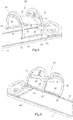
Fig. 1 shows a plan view of a system according to embodiments of the present invention; -
Fig. 2 shows a side view of the system according to embodiments of the present invention; -
Fig. 3 shows a perspective view of the system according to an embodiment of the present invention; -
Fig. 4 shows a perspective view of the system according to an embodiment of the present invention; -
Fig. 5 shows a side view of the system according to embodiments of the present invention; -
Fig. 6 shows a side view of the system according to embodiments of the present invention; -
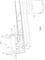
Fig. 7 shows a perspective view of a rail element according to an embodiment of the present invention; -
Fig. 8 shows a perspective view of the rail element and a spring element according to an embodiment of the present invention; -
Figure 1 shows a plan view of asystem 10 according to embodiments of the present invention andFigure 2 shows a side view of the system ofFigure 1 . Thesystem 10 comprises apatient support 12, a treatment table 14, and abed 16 which is movable between thepatient support 12 and the treatment table 14. The treatment table 16 is schematically shown inFigures 1 and 2 and may form part of any medical treatment system but is particularly suitable for use in MR Linac radiotherapy systems. Hence, in embodiments of the present invention, thesystem 10 is arranged at a MR Linac radiotherapy system having radiation heads and radiation sources for generating beams of therapeutic radiation emanating from the radiation heads. One or more collimating elements (e.g. a Multi-leaf collimator in the Linac part) are provided for shaping the beam to conform to a desired cross-section. The radiation heads may be mounted on a rotatable gantry, and controlled to rotate around the patient while directing the radiation towards the axis of rotation and the target within the patient. The target thus receives radiation from multiple angles and a higher dose than the surrounding healthy tissue. The extent of thetreatment area 18, i.e. the volume in which the radiation beam operates, is illustrated schematically inFigures 1 and 2 . - The
patient support 12 may comprise a mechanism for altering the height of the support, for example, between a first height and second height. For example, the first (lower) height may be at a level suitable to allow the patient to climb on to thebed 16, while the second (higher) height is a level equal to the height of the treatment table 14 and allows thebed 16 to move between thesupport 12 and the treatment table 14. - The
bed 12 may be moved in a direction along its longitudinal axis between thesupport 12 and the treatment table 14 in a manner to be described in more detail below. Those skilled in the art will appreciate that any suitable mechanism may be used for moving thebed 16. For example, thebed 16 may be moved by a pulley/belt system, a rack and pinion system, a conveyor belt, etc. - As described above, it is important that the bed can be smoothly transferred or moved between the
support 12 and the treatment table 14 so that once on the table 14 the bed is correctly aligned within the system, which in many radiotherapy systems is crucial. In order to ensure that thebed 16 is correctly aligned during initial set-up and treatment, thesystem 10 may compriseguide elements support 12. Alternatively, guide tracks may be arranged on an upper surface of thesupport 12 and treatment table 14 and corresponding guide rails may be arranged on thepatient bed 16 such that thebed 16 can slide seamlessly between the support and the table. - In the illustrated embodiment, the patient support comprises four pairs of guide elements. However, fewer or more guide pairs may be provided without departing from the scope of the invention. The guide pairs may be uniformly spaced, along the edges of the
support 12 so as to prevent thebed 16 from moving significantly in the lateral direction (i.e. up and down the page inFigure 1 , or into and out of the page inFigure 2 ). - In the embodiment illustrated in
Figure 1 and 2 , the guide elements are rollers which move over the edge of thebed 16 as the bed moved in the direction along its longitudinal axis. However, those skilled in the art will appreciate that any suitable guiding element which provides a low friction surface along which the bed can travel without sticking may be provided as an alternative. Further, guides needs not be identical, and a mix of different guides may be provided in the same system without departing from the scope of the invention. - The treatment table 14 may comprise a plurality of
guide elements support 12. - With reference now to
Fig. 3 ,4 ,5 and 6 , embodiment of the present invention will be described in more detail. AMR coil arrangement 28 including ananterior coil 30 and asupport stand 32 is arranged to be slidable along thepatient bed 16 in a longitudinal direction when a patient is placed on thebed 16. The support stand 32 rests on thepatient bed 16 and is arranged adjacent tolongitudinal edges 23 of thepatient bed 16 and includerails 41 being arranged to be slidable in grooves or guidetracks 43 provided in thepatient bed 16. Thecoil arrangement 28 may further comprise aheight adjustment mechanism 60 for adjusting the height of theanterior coil 30 above thepatient bed 16. Theheight adjustment mechanism 60 may enable an operator to adjust the height of theanterior coil 16 parallel to a plane defined by thepatient bed 16 as indicated infigure 3 or it may enable an operator to adjust theanterior coil 16 in an oblique manner as seen in relation to the plane defined by thepatient bed 16, as shown infigures 5 and 6 . -
Figure 4 further illustrates well how thesupport stand 32 is slid at least partially outward of thepatient bed 16. In particular it is slid outwards and away from a patient mattress region so that the patient can easily positioned on the mattress andpatient bed 16, respectively. While thesupport stand 32 is slid partially outwards of thepatient bed 16 it may still be partially engaged in the guide tracks 43 and thus not fall of. - The support stand 32 comprises at least one arc-shaped
part 34 having afirst end part 36 and asecond end part 38 resting on thepatient bed 16. Eachend part part 34 is slidable by means of therails 41 in acorresponding guide track 43 of thepatient bed 16. Further, theend parts patient bed 16, as shown inFig. 5 and 6 . The first and/orsecond end part part 34 is thus releasable arranged in thecorresponding guide track 43 so as to allow the first and/orsecond end part patient bed 16, as shown inFig. 5 and 6 . According to embodiments of the present invention, at least one arch-shapedpart 34 or therail 41 comprises at least oneflexible rail element 50 arranged to fit into saidguide track 43 and to be moved into and out of saidguide track 43. In the shown embodiment, eachrail 41 or endpart flexible rail elements 50. Eachflexible rail element 50 comprises at least oneprotrusion 52 arranged to releasably snap-lock theend part corresponding guide rail 43 so as to allow therail 41 to slide in theguide track 43 at the same time preventing therail 41 from being removed from saidguide track 43. In embodiments of the present invention, eachflexible rail element 50 comprises fourprotrusions 52, as shown inFig. 7 . - Further, with reference to
Fig. 8 , in embodiments of the present invention, astop device 54 comprising anadjustable spring element 56 is arranged to fit into theflexible rail element 50, wherein theadjustable spring element 56 can be adjusted to adjust a width of theflexible rail element 50 via anadjustment element 58. In the illustrated embodiment, theadjustable spring element 56 is s-shaped. Thus, thespring element 56 will expand the width of therail element 50 when turned and thereby make a sliding movement of thecoil arrangement 28 slower, hence, it requires more power to slide thecoil arrangement 28 along thepatient bed 16. That setting is specifically useful when thecoil arrangement 28 is in its right position and you don't want the patient to accidentally move the coil out of its position. An incident that could happen if the patient for example starts moving his arms. Thespring element 56, or as in the illustrated embodiment the S-shaped element, acts as a spring that alters the spring constant of theflexible rail element 56 when adjusting theadjustment element 58.
Claims (13)
- A system for moving a patient into and from a medical apparatus, comprising:a patient support (12) arranged outside a treatment space of a medical apparatus; a treatment table (14) arranged inside the treatment space in the medical apparatus;a patient bed (16) movable in a longitudinal direction from the patient support to the treatment table and back by means of activation of a transferring mechanism; anda coil arrangement (28) including an anterior coil (30) and a support stand (32), the support stand (32) resting on the patient bed (16) adjacent to longitudinal edges (23) of said patient bed (16) and being slidable along the patient bed (16) in a longitudinal direction.
- The system according to claim 1, wherein the support stand is slidable over and at least partially outward of the patient bed (16) along guide tracks (43) arranged adjacent to said longitudinal edges of said patient bed (16).
- The system according to claim 1 or 2, wherein the support stand comprises at least one arc-shaped part (34) having a first end part (36) and a second end part (38) resting on the patient bed (16), wherein said end parts (36, 38) comprises a rail (41) being slidable in a corresponding guide track (43) of said patient bed (16).
- The system according to claim 3, wherein an end part (34, 36) of said at least one arch-shaped part comprises at least one flexible rail element (50) arranged to fit into said guide track (43) and to be moved into and out of said guide track (43).
- The system according to claim 4, wherein said flexible rail element (50) comprises at least one protrusion (52) arranged to releasably snap-lock said end part (36, 38) in said corresponding guide rail (43) so as to allow the rail (41) to slide in said guide track (43) at the same time preventing said rail (41) from being removed from said guide track (43).
- The system according to claim 1, comprising a stop device (54) with an adjustable spring element (56) arranged to fit into said flexible rail element (50), wherein the adjustable spring element (56) can be adjusted in its width via an adjustment element (58) so that a friction between the spring element (56) and flexible rail element (50), respectively, and the guide track (43) can be adjusted when the support stand (32) is positioned on the guide track (43).
- The system according to claim 6, wherein the adjustable element (56) allows to provide a lower friction limit between the spring element (56) and the flexible rail element (50), respectively, and the guide track (43) that prevents the coil arrangement (28) from moving when the patient accidentally bumps into it.
- The system according to claim 6 or 7, wherein the adjustable element (56) allows to provide an upper friction limit between the spring element (56) and the flexible rail element (50), respectively, and the guide track (43) that allows the coil arrangement (28) to be moved in case the patient panics.
- The system according to claim 6, wherein the adjustable spring element (56) is s-shaped.
- The system according to claim 3 or 4, wherein at least one of the corresponding rails (41) is connected to the first end part (36) and the second end part (38), respectively, in a flexible manner so that the support stand (32) can be rotated about an axis, which is parallel with the longitudinal direction, while the other of the corresponding rails (41) remains engaged in the corresponding guide track (43).
- The system according to claim 4, wherein the flexible rail element (50) allows to rotate the support stand (32) about an axis, which is parallel with the longitudinal direction, while the other of the corresponding rails (41) remains engaged in the corresponding guide track (43).
- The system according to claim 1, wherein the support stand (32) can be rotated at least about an angle of 60° as measured from a plane defined by the patient bed (16) and a plane defined by rails (41) of the support stand (32).
- The system according to claim 1, wherein the coil arrangement (28) comprises a height adjustment mechanism (60) for adjusting the height of the anterior coil (30) above the patient bed (16).
Applications Claiming Priority (1)
| Application Number | Priority Date | Filing Date | Title |
|---|---|---|---|
| US15/484,505 US10206606B2 (en) | 2017-04-11 | 2017-04-11 | Coil arrangement |
Publications (2)
| Publication Number | Publication Date |
|---|---|
| EP3388110A1 true EP3388110A1 (en) | 2018-10-17 |
| EP3388110B1 EP3388110B1 (en) | 2023-01-11 |
Family
ID=61965852
Family Applications (1)
| Application Number | Title | Priority Date | Filing Date |
|---|---|---|---|
| EP18166728.8A Active EP3388110B1 (en) | 2017-04-11 | 2018-04-11 | Coil arrangement |
Country Status (4)
| Country | Link |
|---|---|
| US (1) | US10206606B2 (en) |
| EP (1) | EP3388110B1 (en) |
| CN (1) | CN108686308B (en) |
| AU (1) | AU2018202505B2 (en) |
Cited By (1)
| Publication number | Priority date | Publication date | Assignee | Title |
|---|---|---|---|---|
| CN109481854A (en) * | 2018-12-25 | 2019-03-19 | 南阳市中心医院 | Tumour radiotherapy frame |
Families Citing this family (11)
| Publication number | Priority date | Publication date | Assignee | Title |
|---|---|---|---|---|
| DE102018207636A1 (en) * | 2018-05-16 | 2019-11-21 | Siemens Healthcare Gmbh | Patient table with device for reversible recording of a transfer plate |
| DE202018103733U1 (en) * | 2018-06-29 | 2018-09-27 | Medical Intelligence Medizintechnik Gmbh | Radiotherapy System |
| CN109499017A (en) * | 2019-01-08 | 2019-03-22 | 白雪琴 | A kind of radiotherapy unit of MRI guidance |
| USD956981S1 (en) * | 2019-04-25 | 2022-07-05 | Elekta Instrument Ab | Patient clearance tool |
| CN110200630B (en) * | 2019-05-24 | 2023-06-23 | 上海联影医疗科技股份有限公司 | Coil support for magnetic resonance imaging and magnetic resonance imaging device |
| CN110269770A (en) * | 2019-06-24 | 2019-09-24 | 邹丽丽 | A kind of Neurology inspection lifting apparatus |
| CN111297356A (en) * | 2020-02-17 | 2020-06-19 | 山东省肿瘤防治研究院(山东省肿瘤医院) | Nuclear magnetic accelerator coil measuring device |
| CN111569272A (en) * | 2020-05-27 | 2020-08-25 | 重庆医科大学附属永川医院 | Paediatrics clinician is with paediatrics jaundice treatment device |
| CN112957048B (en) * | 2021-03-23 | 2021-11-19 | 北京未磁科技有限公司 | Position adjusting device for adjusting position of detection equipment and magnetocardiogram instrument |
| CN113876431B (en) * | 2021-10-29 | 2022-09-09 | 中国人民解放军总医院第五医学中心 | Tracking and measuring mechanical arm device of operation sickbed |
| CN114711747A (en) * | 2022-05-18 | 2022-07-08 | 无锡锡州机械有限公司 | Medical nuclear magnetic resonance's coil support |
Citations (7)
| Publication number | Priority date | Publication date | Assignee | Title |
|---|---|---|---|---|
| US5066915A (en) * | 1989-06-28 | 1991-11-19 | Siemens-Asahi Medical System, Ltd. | RF coil positioning device for MRI |
| US5197474A (en) * | 1990-06-14 | 1993-03-30 | Instrumentarium Corp. | Patient bed in a magnetic resonance imaging apparatus |
| EP0857458A1 (en) * | 1996-12-13 | 1998-08-12 | Anil N. Shetty | Movable patient table for imaging device |
| US20070035301A1 (en) * | 2005-08-10 | 2007-02-15 | Kabushiki Kaisha Toshiba | Magnetic resonance imaging apparatus |
| US20090027053A1 (en) * | 2007-07-02 | 2009-01-29 | Guenther Decke | Magnetic resonance examination platform with independently moveable bed and antenna device |
| WO2012143825A1 (en) * | 2011-04-18 | 2012-10-26 | Koninklijke Philips Electronics N.V. | Mri involving a local rf coil being movable relative to a pediatric patient carrier |
| DE102012206920A1 (en) * | 2012-04-26 | 2013-10-31 | Siemens Aktiengesellschaft | Receiving coil system for magnetic resonance imaging scanner, has retention device that is used for positioning receiving coils and is positioned to patient desk at which receiving coils are swingably secured |
Family Cites Families (3)
| Publication number | Priority date | Publication date | Assignee | Title |
|---|---|---|---|---|
| DE19901482B4 (en) * | 1999-01-15 | 2004-01-15 | Siemens Ag | Angio-MR system |
| JP2008253410A (en) * | 2007-04-02 | 2008-10-23 | Toshiba Corp | MRI apparatus and MRI bed apparatus |
| IL226488A (en) * | 2013-05-21 | 2016-07-31 | Aspect Imaging Ltd | Cradle for neonates |
-
2017
- 2017-04-11 US US15/484,505 patent/US10206606B2/en active Active
-
2018
- 2018-04-10 AU AU2018202505A patent/AU2018202505B2/en active Active
- 2018-04-11 CN CN201810323352.9A patent/CN108686308B/en active Active
- 2018-04-11 EP EP18166728.8A patent/EP3388110B1/en active Active
Patent Citations (7)
| Publication number | Priority date | Publication date | Assignee | Title |
|---|---|---|---|---|
| US5066915A (en) * | 1989-06-28 | 1991-11-19 | Siemens-Asahi Medical System, Ltd. | RF coil positioning device for MRI |
| US5197474A (en) * | 1990-06-14 | 1993-03-30 | Instrumentarium Corp. | Patient bed in a magnetic resonance imaging apparatus |
| EP0857458A1 (en) * | 1996-12-13 | 1998-08-12 | Anil N. Shetty | Movable patient table for imaging device |
| US20070035301A1 (en) * | 2005-08-10 | 2007-02-15 | Kabushiki Kaisha Toshiba | Magnetic resonance imaging apparatus |
| US20090027053A1 (en) * | 2007-07-02 | 2009-01-29 | Guenther Decke | Magnetic resonance examination platform with independently moveable bed and antenna device |
| WO2012143825A1 (en) * | 2011-04-18 | 2012-10-26 | Koninklijke Philips Electronics N.V. | Mri involving a local rf coil being movable relative to a pediatric patient carrier |
| DE102012206920A1 (en) * | 2012-04-26 | 2013-10-31 | Siemens Aktiengesellschaft | Receiving coil system for magnetic resonance imaging scanner, has retention device that is used for positioning receiving coils and is positioned to patient desk at which receiving coils are swingably secured |
Cited By (2)
| Publication number | Priority date | Publication date | Assignee | Title |
|---|---|---|---|---|
| CN109481854A (en) * | 2018-12-25 | 2019-03-19 | 南阳市中心医院 | Tumour radiotherapy frame |
| CN109481854B (en) * | 2018-12-25 | 2020-11-03 | 南阳市中心医院 | Oncology radiotherapy stand |
Also Published As
| Publication number | Publication date |
|---|---|
| AU2018202505A1 (en) | 2018-10-25 |
| EP3388110B1 (en) | 2023-01-11 |
| AU2018202505B2 (en) | 2023-11-09 |
| CN108686308B (en) | 2020-11-17 |
| US20180289283A1 (en) | 2018-10-11 |
| CN108686308A (en) | 2018-10-23 |
| US10206606B2 (en) | 2019-02-19 |
Similar Documents
| Publication | Publication Date | Title |
|---|---|---|
| EP3388110B1 (en) | Coil arrangement | |
| KR100449974B1 (en) | Positioning device | |
| US7519149B2 (en) | Small field intensity modulated radiation therapy machine | |
| DE60219059T2 (en) | DEVICE FOR ORIENTING A PATIENT FOR RADIOTHERAPY | |
| DE69319354T2 (en) | FRAME FOR STEREOTACTIC RADIO SURGERY WITH ATTACHMENT TO THE BONE FRAME | |
| US9901501B2 (en) | Patient support system | |
| US6052436A (en) | Radiation therapy device employing cam pin and cam groove guiding system for controlling movement of linear multi-leaf collimator leaves | |
| WO2009129847A1 (en) | Fixation device | |
| CA2528800A1 (en) | Stereotactic upper body fixation and positioning device | |
| CN109481854A (en) | Tumour radiotherapy frame | |
| US11596809B2 (en) | Indicator arrangements and methods for such arrangements | |
| US20110191958A1 (en) | Lithotomy position afterloading carbon fiber treatment couch under image guidance | |
| CN108785876B (en) | Elastic structural element | |
| US20210178191A1 (en) | Radiotherapy system | |
| KR20140070749A (en) | Table for total body irradiation | |
| US8798233B2 (en) | Low dose-rate radiation for medical and veterinary therapies | |
| Theodorou et al. | A new non-invasive and relocatable immobilization frame for fractionated stereotactic radiotherapy | |
| CN110448391A (en) | Fixation device for experimental animal radiotherapy | |
| CN118593922A (en) | Tumor radiotherapy equipment | |
| KR101369983B1 (en) | Device for radiation therapy | |
| RU2732825C1 (en) | Method for pre-radial preparation and irradiation and device for its implementation | |
| US20230102841A1 (en) | Fixation support device for brachytherapy with or without image guidance | |
| RU2632763C1 (en) | Operating table for angiographic manipulations under x-ray control | |
| KR101652575B1 (en) | Dedicated 2D dose array Manipulator with linac-based radiosurgery system |
Legal Events
| Date | Code | Title | Description |
|---|---|---|---|
| PUAI | Public reference made under article 153(3) epc to a published international application that has entered the european phase |
Free format text: ORIGINAL CODE: 0009012 |
|
| STAA | Information on the status of an ep patent application or granted ep patent |
Free format text: STATUS: THE APPLICATION HAS BEEN PUBLISHED |
|
| AK | Designated contracting states |
Kind code of ref document: A1 Designated state(s): AL AT BE BG CH CY CZ DE DK EE ES FI FR GB GR HR HU IE IS IT LI LT LU LV MC MK MT NL NO PL PT RO RS SE SI SK SM TR |
|
| AX | Request for extension of the european patent |
Extension state: BA ME |
|
| STAA | Information on the status of an ep patent application or granted ep patent |
Free format text: STATUS: REQUEST FOR EXAMINATION WAS MADE |
|
| 17P | Request for examination filed |
Effective date: 20190321 |
|
| RBV | Designated contracting states (corrected) |
Designated state(s): AL AT BE BG CH CY CZ DE DK EE ES FI FR GB GR HR HU IE IS IT LI LT LU LV MC MK MT NL NO PL PT RO RS SE SI SK SM TR |
|
| STAA | Information on the status of an ep patent application or granted ep patent |
Free format text: STATUS: EXAMINATION IS IN PROGRESS |
|
| 17Q | First examination report despatched |
Effective date: 20200730 |
|
| INTG | Intention to grant announced |
Effective date: 20221004 |
|
| RIN1 | Information on inventor provided before grant (corrected) |
Inventor name: ALEXIS, HENRIK Inventor name: ELDERED, KJELL Inventor name: CARLSSON, PER |
|
| GRAS | Grant fee paid |
Free format text: ORIGINAL CODE: EPIDOSNIGR3 |
|
| STAA | Information on the status of an ep patent application or granted ep patent |
Free format text: STATUS: GRANT OF PATENT IS INTENDED |
|
| GRAA | (expected) grant |
Free format text: ORIGINAL CODE: 0009210 |
|
| STAA | Information on the status of an ep patent application or granted ep patent |
Free format text: STATUS: THE PATENT HAS BEEN GRANTED |
|
| AK | Designated contracting states |
Kind code of ref document: B1 Designated state(s): AL AT BE BG CH CY CZ DE DK EE ES FI FR GB GR HR HU IE IS IT LI LT LU LV MC MK MT NL NO PL PT RO RS SE SI SK SM TR |
|
| REG | Reference to a national code |
Ref country code: GB Ref legal event code: FG4D |
|
| REG | Reference to a national code |
Ref country code: CH Ref legal event code: EP |
|
| REG | Reference to a national code |
Ref country code: DE Ref legal event code: R096 Ref document number: 602018045228 Country of ref document: DE |
|
| REG | Reference to a national code |
Ref country code: IE Ref legal event code: FG4D |
|
| REG | Reference to a national code |
Ref country code: AT Ref legal event code: REF Ref document number: 1543039 Country of ref document: AT Kind code of ref document: T Effective date: 20230215 |
|
| REG | Reference to a national code |
Ref country code: LT Ref legal event code: MG9D |
|
| REG | Reference to a national code |
Ref country code: NL Ref legal event code: MP Effective date: 20230111 |
|
| REG | Reference to a national code |
Ref country code: AT Ref legal event code: MK05 Ref document number: 1543039 Country of ref document: AT Kind code of ref document: T Effective date: 20230111 |
|
| PG25 | Lapsed in a contracting state [announced via postgrant information from national office to epo] |
Ref country code: NL Free format text: LAPSE BECAUSE OF FAILURE TO SUBMIT A TRANSLATION OF THE DESCRIPTION OR TO PAY THE FEE WITHIN THE PRESCRIBED TIME-LIMIT Effective date: 20230111 |
|
| P01 | Opt-out of the competence of the unified patent court (upc) registered |
Effective date: 20230529 |
|
| PG25 | Lapsed in a contracting state [announced via postgrant information from national office to epo] |
Ref country code: RS Free format text: LAPSE BECAUSE OF FAILURE TO SUBMIT A TRANSLATION OF THE DESCRIPTION OR TO PAY THE FEE WITHIN THE PRESCRIBED TIME-LIMIT Effective date: 20230111 Ref country code: PT Free format text: LAPSE BECAUSE OF FAILURE TO SUBMIT A TRANSLATION OF THE DESCRIPTION OR TO PAY THE FEE WITHIN THE PRESCRIBED TIME-LIMIT Effective date: 20230511 Ref country code: NO Free format text: LAPSE BECAUSE OF FAILURE TO SUBMIT A TRANSLATION OF THE DESCRIPTION OR TO PAY THE FEE WITHIN THE PRESCRIBED TIME-LIMIT Effective date: 20230411 Ref country code: LV Free format text: LAPSE BECAUSE OF FAILURE TO SUBMIT A TRANSLATION OF THE DESCRIPTION OR TO PAY THE FEE WITHIN THE PRESCRIBED TIME-LIMIT Effective date: 20230111 Ref country code: LT Free format text: LAPSE BECAUSE OF FAILURE TO SUBMIT A TRANSLATION OF THE DESCRIPTION OR TO PAY THE FEE WITHIN THE PRESCRIBED TIME-LIMIT Effective date: 20230111 Ref country code: HR Free format text: LAPSE BECAUSE OF FAILURE TO SUBMIT A TRANSLATION OF THE DESCRIPTION OR TO PAY THE FEE WITHIN THE PRESCRIBED TIME-LIMIT Effective date: 20230111 Ref country code: ES Free format text: LAPSE BECAUSE OF FAILURE TO SUBMIT A TRANSLATION OF THE DESCRIPTION OR TO PAY THE FEE WITHIN THE PRESCRIBED TIME-LIMIT Effective date: 20230111 Ref country code: AT Free format text: LAPSE BECAUSE OF FAILURE TO SUBMIT A TRANSLATION OF THE DESCRIPTION OR TO PAY THE FEE WITHIN THE PRESCRIBED TIME-LIMIT Effective date: 20230111 |
|
| PG25 | Lapsed in a contracting state [announced via postgrant information from national office to epo] |
Ref country code: SE Free format text: LAPSE BECAUSE OF FAILURE TO SUBMIT A TRANSLATION OF THE DESCRIPTION OR TO PAY THE FEE WITHIN THE PRESCRIBED TIME-LIMIT Effective date: 20230111 Ref country code: PL Free format text: LAPSE BECAUSE OF FAILURE TO SUBMIT A TRANSLATION OF THE DESCRIPTION OR TO PAY THE FEE WITHIN THE PRESCRIBED TIME-LIMIT Effective date: 20230111 Ref country code: IS Free format text: LAPSE BECAUSE OF FAILURE TO SUBMIT A TRANSLATION OF THE DESCRIPTION OR TO PAY THE FEE WITHIN THE PRESCRIBED TIME-LIMIT Effective date: 20230511 Ref country code: GR Free format text: LAPSE BECAUSE OF FAILURE TO SUBMIT A TRANSLATION OF THE DESCRIPTION OR TO PAY THE FEE WITHIN THE PRESCRIBED TIME-LIMIT Effective date: 20230412 Ref country code: FI Free format text: LAPSE BECAUSE OF FAILURE TO SUBMIT A TRANSLATION OF THE DESCRIPTION OR TO PAY THE FEE WITHIN THE PRESCRIBED TIME-LIMIT Effective date: 20230111 |
|
| REG | Reference to a national code |
Ref country code: DE Ref legal event code: R097 Ref document number: 602018045228 Country of ref document: DE |
|
| PG25 | Lapsed in a contracting state [announced via postgrant information from national office to epo] |
Ref country code: SM Free format text: LAPSE BECAUSE OF FAILURE TO SUBMIT A TRANSLATION OF THE DESCRIPTION OR TO PAY THE FEE WITHIN THE PRESCRIBED TIME-LIMIT Effective date: 20230111 Ref country code: RO Free format text: LAPSE BECAUSE OF FAILURE TO SUBMIT A TRANSLATION OF THE DESCRIPTION OR TO PAY THE FEE WITHIN THE PRESCRIBED TIME-LIMIT Effective date: 20230111 Ref country code: EE Free format text: LAPSE BECAUSE OF FAILURE TO SUBMIT A TRANSLATION OF THE DESCRIPTION OR TO PAY THE FEE WITHIN THE PRESCRIBED TIME-LIMIT Effective date: 20230111 Ref country code: DK Free format text: LAPSE BECAUSE OF FAILURE TO SUBMIT A TRANSLATION OF THE DESCRIPTION OR TO PAY THE FEE WITHIN THE PRESCRIBED TIME-LIMIT Effective date: 20230111 Ref country code: CZ Free format text: LAPSE BECAUSE OF FAILURE TO SUBMIT A TRANSLATION OF THE DESCRIPTION OR TO PAY THE FEE WITHIN THE PRESCRIBED TIME-LIMIT Effective date: 20230111 |
|
| PLBE | No opposition filed within time limit |
Free format text: ORIGINAL CODE: 0009261 |
|
| STAA | Information on the status of an ep patent application or granted ep patent |
Free format text: STATUS: NO OPPOSITION FILED WITHIN TIME LIMIT |
|
| PG25 | Lapsed in a contracting state [announced via postgrant information from national office to epo] |
Ref country code: SK Free format text: LAPSE BECAUSE OF FAILURE TO SUBMIT A TRANSLATION OF THE DESCRIPTION OR TO PAY THE FEE WITHIN THE PRESCRIBED TIME-LIMIT Effective date: 20230111 |
|
| REG | Reference to a national code |
Ref country code: CH Ref legal event code: PL |
|
| 26N | No opposition filed |
Effective date: 20231012 |
|
| PG25 | Lapsed in a contracting state [announced via postgrant information from national office to epo] |
Ref country code: LU Free format text: LAPSE BECAUSE OF NON-PAYMENT OF DUE FEES Effective date: 20230411 |
|
| REG | Reference to a national code |
Ref country code: BE Ref legal event code: MM Effective date: 20230430 |
|
| PG25 | Lapsed in a contracting state [announced via postgrant information from national office to epo] |
Ref country code: MC Free format text: LAPSE BECAUSE OF FAILURE TO SUBMIT A TRANSLATION OF THE DESCRIPTION OR TO PAY THE FEE WITHIN THE PRESCRIBED TIME-LIMIT Effective date: 20230111 |
|
| PG25 | Lapsed in a contracting state [announced via postgrant information from national office to epo] |
Ref country code: SI Free format text: LAPSE BECAUSE OF FAILURE TO SUBMIT A TRANSLATION OF THE DESCRIPTION OR TO PAY THE FEE WITHIN THE PRESCRIBED TIME-LIMIT Effective date: 20230111 Ref country code: MC Free format text: LAPSE BECAUSE OF FAILURE TO SUBMIT A TRANSLATION OF THE DESCRIPTION OR TO PAY THE FEE WITHIN THE PRESCRIBED TIME-LIMIT Effective date: 20230111 Ref country code: LI Free format text: LAPSE BECAUSE OF NON-PAYMENT OF DUE FEES Effective date: 20230430 Ref country code: CH Free format text: LAPSE BECAUSE OF NON-PAYMENT OF DUE FEES Effective date: 20230430 |
|
| REG | Reference to a national code |
Ref country code: IE Ref legal event code: MM4A |
|
| PG25 | Lapsed in a contracting state [announced via postgrant information from national office to epo] |
Ref country code: BE Free format text: LAPSE BECAUSE OF NON-PAYMENT OF DUE FEES Effective date: 20230430 |
|
| PG25 | Lapsed in a contracting state [announced via postgrant information from national office to epo] |
Ref country code: IE Free format text: LAPSE BECAUSE OF NON-PAYMENT OF DUE FEES Effective date: 20230411 |
|
| PG25 | Lapsed in a contracting state [announced via postgrant information from national office to epo] |
Ref country code: IE Free format text: LAPSE BECAUSE OF NON-PAYMENT OF DUE FEES Effective date: 20230411 |
|
| PG25 | Lapsed in a contracting state [announced via postgrant information from national office to epo] |
Ref country code: IT Free format text: LAPSE BECAUSE OF FAILURE TO SUBMIT A TRANSLATION OF THE DESCRIPTION OR TO PAY THE FEE WITHIN THE PRESCRIBED TIME-LIMIT Effective date: 20230111 |
|
| PG25 | Lapsed in a contracting state [announced via postgrant information from national office to epo] |
Ref country code: BG Free format text: LAPSE BECAUSE OF FAILURE TO SUBMIT A TRANSLATION OF THE DESCRIPTION OR TO PAY THE FEE WITHIN THE PRESCRIBED TIME-LIMIT Effective date: 20230111 |
|
| PG25 | Lapsed in a contracting state [announced via postgrant information from national office to epo] |
Ref country code: BG Free format text: LAPSE BECAUSE OF FAILURE TO SUBMIT A TRANSLATION OF THE DESCRIPTION OR TO PAY THE FEE WITHIN THE PRESCRIBED TIME-LIMIT Effective date: 20230111 |
|
| PGFP | Annual fee paid to national office [announced via postgrant information from national office to epo] |
Ref country code: DE Payment date: 20250305 Year of fee payment: 8 |
|
| PG25 | Lapsed in a contracting state [announced via postgrant information from national office to epo] |
Ref country code: CY Free format text: LAPSE BECAUSE OF FAILURE TO SUBMIT A TRANSLATION OF THE DESCRIPTION OR TO PAY THE FEE WITHIN THE PRESCRIBED TIME-LIMIT; INVALID AB INITIO Effective date: 20180411 |
|
| PG25 | Lapsed in a contracting state [announced via postgrant information from national office to epo] |
Ref country code: HU Free format text: LAPSE BECAUSE OF FAILURE TO SUBMIT A TRANSLATION OF THE DESCRIPTION OR TO PAY THE FEE WITHIN THE PRESCRIBED TIME-LIMIT; INVALID AB INITIO Effective date: 20180411 |
|
| PG25 | Lapsed in a contracting state [announced via postgrant information from national office to epo] |
Ref country code: TR Free format text: LAPSE BECAUSE OF FAILURE TO SUBMIT A TRANSLATION OF THE DESCRIPTION OR TO PAY THE FEE WITHIN THE PRESCRIBED TIME-LIMIT Effective date: 20230111 |
|
| PGFP | Annual fee paid to national office [announced via postgrant information from national office to epo] |
Ref country code: GB Payment date: 20260223 Year of fee payment: 9 |
|
| PGFP | Annual fee paid to national office [announced via postgrant information from national office to epo] |
Ref country code: FR Payment date: 20260309 Year of fee payment: 9 |