EP3388009B1 - Electrosurgical device having easily adjustable length - Google Patents
Electrosurgical device having easily adjustable length Download PDFInfo
- Publication number
- EP3388009B1 EP3388009B1 EP16873157.8A EP16873157A EP3388009B1 EP 3388009 B1 EP3388009 B1 EP 3388009B1 EP 16873157 A EP16873157 A EP 16873157A EP 3388009 B1 EP3388009 B1 EP 3388009B1
- Authority
- EP
- European Patent Office
- Prior art keywords
- guide
- contact
- disposed
- electrosurgical device
- space
- Prior art date
- Legal status (The legal status is an assumption and is not a legal conclusion. Google has not performed a legal analysis and makes no representation as to the accuracy of the status listed.)
- Active
Links
Images





Classifications
-
- A—HUMAN NECESSITIES
- A61—MEDICAL OR VETERINARY SCIENCE; HYGIENE
- A61B—DIAGNOSIS; SURGERY; IDENTIFICATION
- A61B18/00—Surgical instruments, devices or methods for transferring non-mechanical forms of energy to or from the body
- A61B18/04—Surgical instruments, devices or methods for transferring non-mechanical forms of energy to or from the body by heating
- A61B18/12—Surgical instruments, devices or methods for transferring non-mechanical forms of energy to or from the body by heating by passing a current through the tissue to be heated, e.g. high-frequency current
- A61B18/14—Probes or electrodes therefor
- A61B18/148—Probes or electrodes therefor having a short, rigid shaft for accessing the inner body transcutaneously, e.g. for neurosurgery or arthroscopy
-
- A—HUMAN NECESSITIES
- A61—MEDICAL OR VETERINARY SCIENCE; HYGIENE
- A61B—DIAGNOSIS; SURGERY; IDENTIFICATION
- A61B18/00—Surgical instruments, devices or methods for transferring non-mechanical forms of energy to or from the body
- A61B18/04—Surgical instruments, devices or methods for transferring non-mechanical forms of energy to or from the body by heating
- A61B18/12—Surgical instruments, devices or methods for transferring non-mechanical forms of energy to or from the body by heating by passing a current through the tissue to be heated, e.g. high-frequency current
- A61B18/14—Probes or electrodes therefor
- A61B18/1402—Probes for open surgery
-
- A—HUMAN NECESSITIES
- A61—MEDICAL OR VETERINARY SCIENCE; HYGIENE
- A61B—DIAGNOSIS; SURGERY; IDENTIFICATION
- A61B17/00—Surgical instruments, devices or methods
- A61B2017/00831—Material properties
- A61B2017/00862—Material properties elastic or resilient
-
- A—HUMAN NECESSITIES
- A61—MEDICAL OR VETERINARY SCIENCE; HYGIENE
- A61B—DIAGNOSIS; SURGERY; IDENTIFICATION
- A61B17/00—Surgical instruments, devices or methods
- A61B2017/00982—General structural features
- A61B2017/00991—Telescopic means
-
- A—HUMAN NECESSITIES
- A61—MEDICAL OR VETERINARY SCIENCE; HYGIENE
- A61B—DIAGNOSIS; SURGERY; IDENTIFICATION
- A61B18/00—Surgical instruments, devices or methods for transferring non-mechanical forms of energy to or from the body
- A61B2018/00053—Mechanical features of the instrument of device
- A61B2018/00184—Moving parts
- A61B2018/00196—Moving parts reciprocating lengthwise
-
- A—HUMAN NECESSITIES
- A61—MEDICAL OR VETERINARY SCIENCE; HYGIENE
- A61B—DIAGNOSIS; SURGERY; IDENTIFICATION
- A61B18/00—Surgical instruments, devices or methods for transferring non-mechanical forms of energy to or from the body
- A61B2018/00571—Surgical instruments, devices or methods for transferring non-mechanical forms of energy to or from the body for achieving a particular surgical effect
- A61B2018/00601—Cutting
-
- A—HUMAN NECESSITIES
- A61—MEDICAL OR VETERINARY SCIENCE; HYGIENE
- A61B—DIAGNOSIS; SURGERY; IDENTIFICATION
- A61B18/00—Surgical instruments, devices or methods for transferring non-mechanical forms of energy to or from the body
- A61B2018/0091—Handpieces of the surgical instrument or device
-
- A—HUMAN NECESSITIES
- A61—MEDICAL OR VETERINARY SCIENCE; HYGIENE
- A61B—DIAGNOSIS; SURGERY; IDENTIFICATION
- A61B18/00—Surgical instruments, devices or methods for transferring non-mechanical forms of energy to or from the body
- A61B2018/0091—Handpieces of the surgical instrument or device
- A61B2018/00916—Handpieces of the surgical instrument or device with means for switching or controlling the main function of the instrument or device
- A61B2018/0094—Types of switches or controllers
-
- A—HUMAN NECESSITIES
- A61—MEDICAL OR VETERINARY SCIENCE; HYGIENE
- A61B—DIAGNOSIS; SURGERY; IDENTIFICATION
- A61B18/00—Surgical instruments, devices or methods for transferring non-mechanical forms of energy to or from the body
- A61B2018/0091—Handpieces of the surgical instrument or device
- A61B2018/00916—Handpieces of the surgical instrument or device with means for switching or controlling the main function of the instrument or device
- A61B2018/00958—Handpieces of the surgical instrument or device with means for switching or controlling the main function of the instrument or device for switching between different working modes of the main function
-
- A—HUMAN NECESSITIES
- A61—MEDICAL OR VETERINARY SCIENCE; HYGIENE
- A61B—DIAGNOSIS; SURGERY; IDENTIFICATION
- A61B18/00—Surgical instruments, devices or methods for transferring non-mechanical forms of energy to or from the body
- A61B18/04—Surgical instruments, devices or methods for transferring non-mechanical forms of energy to or from the body by heating
- A61B18/12—Surgical instruments, devices or methods for transferring non-mechanical forms of energy to or from the body by heating by passing a current through the tissue to be heated, e.g. high-frequency current
- A61B18/14—Probes or electrodes therefor
- A61B2018/1405—Electrodes having a specific shape
- A61B2018/1412—Blade
-
- A—HUMAN NECESSITIES
- A61—MEDICAL OR VETERINARY SCIENCE; HYGIENE
- A61B—DIAGNOSIS; SURGERY; IDENTIFICATION
- A61B18/00—Surgical instruments, devices or methods for transferring non-mechanical forms of energy to or from the body
- A61B18/04—Surgical instruments, devices or methods for transferring non-mechanical forms of energy to or from the body by heating
- A61B18/12—Surgical instruments, devices or methods for transferring non-mechanical forms of energy to or from the body by heating by passing a current through the tissue to be heated, e.g. high-frequency current
- A61B18/14—Probes or electrodes therefor
- A61B2018/1475—Electrodes retractable in or deployable from a housing
-
- A—HUMAN NECESSITIES
- A61—MEDICAL OR VETERINARY SCIENCE; HYGIENE
- A61B—DIAGNOSIS; SURGERY; IDENTIFICATION
- A61B2218/00—Details of surgical instruments, devices or methods for transferring non-mechanical forms of energy to or from the body
- A61B2218/001—Details of surgical instruments, devices or methods for transferring non-mechanical forms of energy to or from the body having means for irrigation and/or aspiration of substances to and/or from the surgical site
- A61B2218/007—Aspiration
Definitions
- the present invention relates to an electrosurgical device having an easily adjustable length and, more particularly to an electrosurgical device of which the entire length can be easily adjusted by allowing a stretching member having a blade to be easily moved in a body in a one-touch button type.
- an electrosurgical unit is a representative medial instrument that is used to incise a portion of tissues of a human body or coagulate tissues and blood in a surgical operation, using electricity, instead of surgical knives.
- the electrosurgical unit which uses a principle that generates a short spark or heat without applying electric shock or stimulation to a muscle when a high-frequency current flows through a human body, incises a desired tissue of a body, using high-frequency energy of about 100°C or coagulates a tissue, using high-frequency energy of about 60°C.
- electrosurgical units of the related art cannot be adjusted in the entire length, so it is required to prepare several electrosurgical units with blades having different lengths, for example, in order to insert a blade into deep into a human body, depending on the positions to be operated or to use a blade on the surface of a human body.
- an adjustable electrocautery surgical apparatus for selectively delivering electrosurgical coagulation and cut current from an electrosurgical generator to a surgical site
- a longitudinal channel passes through a sidewall of the elongated body member.
- a plurality of stops are positioned in the channel for providing a sequence of stop positions between maximally retracted and maximally extended positions of the apparatus.
- the adjustable lock is slidably positioned in the longitudinal channel of the elongated body member so as to selectively engage the stops and thereby lock the electrode blade in a selected stop position between the maximally retracted and the maximally extended positions.
- the apparatus is further provided with means for electrically coupling the electrode blade to the coagulation and cut currents of the electrosurgical generator, such that coagulation or cut current, or a combination thereof, can be selectively delivered to the electrode blade.
- surgical pencils which define a channel to enable suctioning of materials and methods of operating the surgical pencils.
- the surgical pencils perform cutting and coagulation.
- a multifunctional telescopic monopolar/bipolar electrosurgery pencil for use with an electrosurgery unit (ESU).
- the monopolar/bipolar electrosurgery pencil includes a bipolar electrode having an insulator sandwiched between an active electrode and a return electrode wherein the bipolar electrode is connected to a handpiece capable of alternately effectuating cutting and coagulation with the bipolar electrode.
- the monopolar /bipolar electrosurgery pencil is capable of functioning as both a monopolar and bipolar device and can be used for open and closed laparoscopic and endoscopic procedures.
- Telescopic means for adjusting the length of the bipolar electrode is also provided as are means for smoke evacuation and suction/irrigation.
- the multifunctional telescopic monopolar/bipolar device can also be adapted for use with an ESU argon beam coagulator.
- an object of the present invention is to provide an electrosurgical device of which the entire length can be easily adjusted by allowing a stretching member having a blade to be easily moved in a body in a one-touch button type.
- the button stopper may have a rotation guide rotatably disposed in the space of the body, a button portion extending upward to be exposed over the space at a first side of the rotation guide, and a locking portion extending at a second side of the rotation guide to be locked to the locking steps; and when the button portion is pressed down, the locking portion may be lifted not to be locked to the locking steps, and when the button portion is pressed up, the locking portion may be moved down to be locked to the locking steps.
- the electrosurgical device may further include an elastic member supported to face a bottom of the button portion in the space to press up the button portion.
- the electrosurgical device may further include an elastic member supported to face a top of the locking portion in the space to press down the locking portion such that the button portion is pressed up.
- the elastic member may include any one selected from a plate spring, a coil spring, and a rubber member.
- a first guide may protrude upward from the locking portion, a second guide may be formed on an inner side of the body at a position facing the first guide, and the elastic member may be disposed between the first guide and the second guide.
- the space may include a first receiving portion disposed over a top plate longitudinally elongated therein and a second receiving portion disposed under the top plate with longitudinal front and rear thereof open; the operation member of the operation unit and the substrate may be disposed in the first receiving portion; the contact member of the operation unit may be elongated in the second receiving portion and electrically connected with the substrate through the top plate; the stretching member may be disposed in the second receiving portion under the contact member to be movable forward out of the second receiving portion or into the second receiving portion, and may have a suction passage longitudinally formed therein; the contact guide may have a first end disposed in the suction passage and a second end extending toward the contact member through the suction passage; the button stopper may be rotatably supported on the top plate with a first side exposed out of the body and a second side disposed to or not to be locked to the locking steps through the top plate; and the blade may be coupled to the first end of the contact guide and may extend out of the suction passage.
- the contact guide may have a front end extending toward a front of the suction passage where the blade is disposed, a rear end extending to a rear of the suction passage, and a contact terminal bent toward the contact member at the rear; and the contact terminal may be configured to be in contact with the contact member, so power applied to the contact member may be transmitted to the blade connected with the contact guide.
- a cut guide may be formed by cutting forward a rear, where the contact terminal is disposed, of the stretching member, and the contact terminal may be guided in the cut guide.
- a coupling guide may be inserted in a front, which faces the blade, of the suction passage, and the blade may be fitted in a first end of the coupling guide, the contact guide may be fitted in a second end of the coupling guide, and the blade and the coupling guide may be electrically connected to each other.
- the stretching member combined with the blade can be easily moved in the body, and accordingly, the entire length can be easily adjusted. Accordingly, an operator can easily insert the blade through incised skin of a patient.
- the stretching member when the stretching member is unlocked and the entire length is adjusted, the elastic member presses up the button, so the stretching member is naturally locked. Accordingly, an operator does not need to specifically lock the stretching member 300 in complicated operation environments.
- Electrosurgical device 100 Body 110: Upper body 110a: First receiving portion 111: Operation hole 112: Button hole 114: Second guide 120: Lower body 120a: Second receiving portion 122: Top plate 122a: Projection hole 124: Button guide 124a: Coupling pivot 124b: Locking guide 124c: Downward guide 200: Operation unit 210: Operation member 220: Substrate 230: Contact member 232: Contact protrusion 300: Stretching member 300a: Suction passage 302: Locking step 304: Cut guide 310: Coupling guide 312: Coupling portion 400: Button stopper 402: Rotation guide 404: Locking portion 405: First guide 406: Button portion 450, 460: Elastic member 500: Contact guide 502: Blade coupling portion 504: Contact terminal 600: Blade
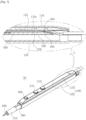
- FIG. 1 is a view schematically showing an electrosurgical device having an easily adjustable length according to an embodiment of the present invention.
- an electrosurgical device 50 having an easily adjustable length which is used for an operator such as a doctor to incise or coagulate a portion of a tissue of a human body, includes a body 100, an operation unit 200 (shown in FIG. 2 ), a stretching member 300, a button stopper 400, a contact guide 500 (shown in FIG. 2 ), and a blade 600.
- the direction close to a tissue of a human body is defined as a forward direction and the opposite direction is defined as a backward direction when a user incises or coagulates a tissue of a human body, using the blade 600 with the body 100 in his/her hand.
- FIGS. 2 and 3 Detailed configurations of the components are described hereafter with reference to FIGS. 2 and 3 .
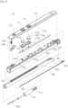
- FIG. 2 is an exploded view showing the electrosurgical device having an easily adjustable length according to an embodiment of the present invention.
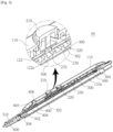
- FIG. 3 is a cross-sectional view schematically showing the electrosurgical device having an easily adjustable length according to an embodiment of the present invention.
- the body 100 which is a part that a user holds with his/her hand, is elongated in a longitudinal direction and has a space longitudinally defined therein.
- the body 100 may include a lower body 120 longitudinally elongated and an upper body 110 disposed over the lower body 120.
- the upper body 110 and the lower body 120 may be integrated in one unit.
- the space may have a first receiving portion 110a disposed between a top plate 122 disposed on the top of the lower body 120 and the upper body 110 and a second receiving portion 120a disposed under the top plate 122, that is, in the lower body 120.
- the second receiving portion 120a may be open at the front and rear longitudinal ends.
- the operation unit 200 includes operation members 210, a substrate 220, and a contact member 230.
- the operation member 210 for example, which may be one or more buttons or touch panels, are disposed at a predetermined distance backward from the front of the first receiving portion 110a, and have tops that are open through the top of the first receiving portion 110a.
- Operation holes 111 are formed through the upper body 110 at positions corresponding to the operation members 210 and the operation members 210 are exposed through the operation holes 111.
- the substrate 220 is, for example, a PCB (Printed Circuit Board), is disposed in the first receiving portion 110a to face the operation members 210, and is electrically connected with the operation members 210.
- PCB Print Circuit Board
- the substrate adjusts the amount of high-frequency energy applied from the outside when the operation members 210 are operated, and then transmits the high-frequency energy to the blade 600 to be described below.
- the contact member 230 is made of a conductive material, is elongated backward along the top of the second receiving portion 120a of the lower body 120, and has contact projections 232 to be electrically connected with the substrate 220 through the top plate 122 disposed on the second receiving portion 120a.
- Projection holes 122a are formed through the top plate 122 at positions corresponding to the contact projections 232, so the contact projections 232 are electrically connected with the substrate 220 through the projection holes 122a.
- the stretching member 300 is inserted in the second receiving portion 120a and positioned under the contact member 230 disposed on the second receiving portion 120a.
- the stretching member 300 is configured to be able to longitudinally move in the second receiving portion 120a, and has a suction passage 300a longitudinally formed therein and a plurality of locking steps 302 longitudinally formed from the front portion to the rear portion on the top facing the first receiving portion 110a.
- a coupling guide 310 may be coupled to the front of the suction passage 300a of the stretching member 300 and the rear of the suction passage 300a of the stretching member 300 may be positioned inward further than the rear of the second receiving portion 120a.
- the coupling guide 310 is formed in a cylindrical shape and has a coupling portion 312 of which both ends are open, at the rear thereof.
- a suction unit (not shown) having a smoke evacuator is connected to the rear of the second receiving portion 120a to suction air so that smoke that is dispersed around the blade 600 when a user incises or coagulates a portion of a tissue of the body of a patient, using the blade 600, is easily suctioned into the suction passage 300a and the second receiving portion 120a.
- the button stopper 400 and the elastic member 450 restrict movement of the stretching member 300 and are described with reference to FIG. 4 .
- the contact guide 500 is made of a conductive material, is elongated in the longitudinal direction of the suction passage 300a, and has a blade coupling portion 502 at the longitudinal front end and a contact terminal 504 bending toward the contact member through the suction passage 300a, at the longitudinal rear end thereof.
- the blade coupling portion 502 is inserted and fixed in the rear portion of the coupling portion 312 of the coupling guide 310.
- the blade 600 is longitudinally elongated with an end inserted in the front portion of the coupling portion 312 of the coupling guide 310 and electrically connected with the blade coupling portion 502 of the contact guide 500 and the other end extending into the front portion of the suction passage 300a.
- High-frequency energy applied to the substrate 200 from the outside is transmitted to the blade 600 through the contact member 230 and the contact guide 500, so a portion of the tissue of the patient's body is incised or coagulated by the high-frequency energy.
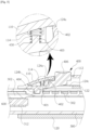
- FIG. 4 is view showing the button stopper and the elastic member combined with a body of the electrosurgical device having an easily adjustable length according to an embodiment of the present invention.
- FIG. 5 is a cross-sectional view showing the button stopper and the elastic member combined with the body of the electrosurgical device having an easily adjustable length according to an embodiment of the present invention.
- the button stopper 400 which is rotated on the body 100 to or not to be locked to the locking steps 302, has a rotation guide 402 rotatably disposed on the top plate 122 of the lower body 120, a locking portion 404 extending from the longitudinal front of the rotation guide 402 to be locked to the locking steps 302, and a button portion 406 extending upward to be exposed from the longitudinal rear of the rotation guide 402.
- a first guide 405 protrudes upward from the locking portion 404 and a second guide 114 protrudes from the inner side of the upper body 110 to face the first guide 405.
- the second guide 114 is formed in a ring shape.
- the elastic member 450 to be described below is fitted between the first guide 405 and the second guide 114.
- the elastic member 450 which presses upward the button portion 406 by applying downward to the locking portion 404 of the button stopper 400, may include a plate spring, a coil spring, and a rubber member.
- the elastic member 450 is fitted between the first guide 405 and the second guide 114, whereby it is supported by the first guide 405 and pressed downward the locking portion 404 connected with the second guide 114.
- a button hole 112 is formed at the position corresponding to the button portion 406 of the upper body 110, so the button portion 406 is exposed to the outside through the button hole 112.
- a button guide 124 is formed on the top plate 122 of the lower body 120 at a position corresponding to the button stopper 400.
- the button guide 124 has a coupling pivot 124a in which the rotation guide 402 is rotatably inserted, a locking guide 124b formed through the top plate at the front of the coupling pivot 124a such that the locking portion 404 is inserted in the second receiving portion 120a of the lower body 120, and a downward guide 124c formed through the top plate at the rear of the coupling pivot 124a such that the rear of the rotation guide 402 is inserted in the second receiving portion 120a.
- the locking portion 404 When the button 406 is pressed down, the locking portion 404 is lifted not to be locked to the locking steps 302. Further, when the button portion 406 is pressed up, the locking portion 404 is moved down and locked to the locking steps 302. When the locking portion 404 of the button stopper 400 is locked to the locking steps 302, the stretching member 300 is locked and restricted in movement.
- the stretching member 300 is unlocked. Further, as the stretching member 300 is unlocked, the stretching member 300 is moved in the lower body 120, so the entire length is adjusted. Further, when the entire length is adjusted, the elastic member 450 presses up the button portion 406 and the stretching member 300 is naturally locked. Accordingly, an operator does not need to specifically lock the stretching member 300 in complicated operation environments.
- FIG. 6 is a view showing another example of the button stopper and the elastic member combined with the body of the electrosurgical device having an easily adjustable length according to an embodiment of the present invention.
- FIG. 7 is a view showing the contact member and the contact guide that are in contact with each other in the electrosurgical device having an easily adjustable length according to an embodiment of the present invention.
- a cut guide 304 is elongated toward the front of the stretching member 300 at the rear portion of the stretching member 300.
- the contact member 230 is elongated to cover the cut guide 304.
- the contact terminal 504 of the contact guide 500 is bent toward the cut guide 304 to be in contact with the contact member 230 through the cut guide 304.
- the contact terminal 504 of the contact guide 500 connected with the stretching member 300 is also moved forward or backward, in which the contact terminal 504 is moved forward or backward in contact with the contact member 230 disposed on the stretching member 300.
- FIG. 8 is a view showing forward movement of the stretching member in the electrosurgical device having an easily adjustable length according to an embodiment of the present invention.
- the electrosurgical device 50 having an easily adjustable length
- the button portion 406 of the button stopper 400 is pressed down
- the locking portion 404 of the button stopper 400 is lifted and the stretching member 300 is unlocked.
- the stretching member 300 is moved forward or backward in the second receiving portion 120a, so the entire length is easily adjusted.
- FIGS. 9 and 10 are views schematically showing a difference in insertion depth in a skin tissue, depending on the position of the stretching unit in the electrosurgical device having an easily adjustable length according to an embodiment of the present invention.
- an operator holds the body 100 and inserts the blade 600 through incised skin S.
- the stretching member 300 since the stretching member 300 has been moved backward, the lengths of the body 100 and the blade 600 is too small, so the blade 600 cannot be pushed deep into the incised skin S.
- the operator holding the body 100 moves the stretching member 300 forward in the second receiving portion 120a by pressing down the button portion 406 of the button stopper 400.
- the operator holds with his/her hand and moves forward the stretching member 300.
- the blade 600 is moved forward together with the stretching member 300.
- the locking portion 404 of the button stopper 400 is locked to the locking steps 302 of the stretching member 300, whereby the stretching member 300 is naturally locked.
- the stretching member 300 in one-touch button type that pressing down the button portion 406 once, the stretching member 300 combined with the blade 600 can be easily moved in the body 100, and accordingly, the entire length can be easily adjusted. Accordingly, an operator can easily insert the blade 600 through incised skin of a patient.
Landscapes
- Health & Medical Sciences (AREA)
- Surgery (AREA)
- Engineering & Computer Science (AREA)
- Life Sciences & Earth Sciences (AREA)
- Heart & Thoracic Surgery (AREA)
- Animal Behavior & Ethology (AREA)
- Nuclear Medicine, Radiotherapy & Molecular Imaging (AREA)
- Otolaryngology (AREA)
- Veterinary Medicine (AREA)
- Public Health (AREA)
- Physics & Mathematics (AREA)
- Biomedical Technology (AREA)
- Medical Informatics (AREA)
- Molecular Biology (AREA)
- Plasma & Fusion (AREA)
- General Health & Medical Sciences (AREA)
- Neurosurgery (AREA)
- Neurology (AREA)
- Surgical Instruments (AREA)
Description
- The present invention relates to an electrosurgical device having an easily adjustable length and, more particularly to an electrosurgical device of which the entire length can be easily adjusted by allowing a stretching member having a blade to be easily moved in a body in a one-touch button type.
- In general, an electrosurgical unit (ESU) is a representative medial instrument that is used to incise a portion of tissues of a human body or coagulate tissues and blood in a surgical operation, using electricity, instead of surgical knives.
- The electrosurgical unit, which uses a principle that generates a short spark or heat without applying electric shock or stimulation to a muscle when a high-frequency current flows through a human body, incises a desired tissue of a body, using high-frequency energy of about 100°C or coagulates a tissue, using high-frequency energy of about 60°C.
- However, such electrosurgical units of the related art cannot be adjusted in the entire length, so it is required to prepare several electrosurgical units with blades having different lengths, for example, in order to insert a blade into deep into a human body, depending on the positions to be operated or to use a blade on the surface of a human body.
- With respect to the prior art attention is drawn to
US 6,197,024 B from which an adjustable electrocautery surgical apparatus for selectively delivering electrosurgical coagulation and cut current from an electrosurgical generator to a surgical site is known comprising an elongated body, an extension member passing at least partially through the elongated body, a track in the elongated body for guiding the extension member, an electrode blade attached to the extension member for cutting or coagulating tissue, and an adjustable lock coupled to the extension member for selectively adjusting the position of the extension member and electrode blade relative to the elongated body and for locking the extension member and electrode blade in a selected position. A longitudinal channel passes through a sidewall of the elongated body member. A plurality of stops are positioned in the channel for providing a sequence of stop positions between maximally retracted and maximally extended positions of the apparatus. The adjustable lock is slidably positioned in the longitudinal channel of the elongated body member so as to selectively engage the stops and thereby lock the electrode blade in a selected stop position between the maximally retracted and the maximally extended positions. The apparatus is further provided with means for electrically coupling the electrode blade to the coagulation and cut currents of the electrosurgical generator, such that coagulation or cut current, or a combination thereof, can be selectively delivered to the electrode blade. - Further, from
US 2015/0216618 A1 surgical pencils are known which define a channel to enable suctioning of materials and methods of operating the surgical pencils. In one example embodiment, the surgical pencils perform cutting and coagulation. - From
US 2005/0113825 A1 a multifunctional telescopic monopolar/bipolar electrosurgery pencil is known for use with an electrosurgery unit (ESU). The monopolar/bipolar electrosurgery pencil includes a bipolar electrode having an insulator sandwiched between an active electrode and a return electrode wherein the bipolar electrode is connected to a handpiece capable of alternately effectuating cutting and coagulation with the bipolar electrode. The monopolar /bipolar electrosurgery pencil is capable of functioning as both a monopolar and bipolar device and can be used for open and closed laparoscopic and endoscopic procedures. Telescopic means for adjusting the length of the bipolar electrode is also provided as are means for smoke evacuation and suction/irrigation. The multifunctional telescopic monopolar/bipolar device can also be adapted for use with an ESU argon beam coagulator. - In order to solve the problems of the related art, an object of the present invention is to provide an electrosurgical device of which the entire length can be easily adjusted by allowing a stretching member having a blade to be easily moved in a body in a one-touch button type.
- In order to achieve the objects, an electrosurgical device having an easily adjustable length includes: a body elongated in a longitudinal direction and having a space longitudinally defined therein; an operation unit having an operation member with a first side disposed in the space and a second side exposed over the space, a substrate disposed in the space and electrically connected with the operation member, and a contact member elongated in the space with a top thereof in electrical contact with the substrate; a stretching member being slidable in the space and having a plurality of locking steps longitudinally formed on a top thereof; a button stopper supported and moved on the body to or not to be locked to the locking steps; a contact guide with a first end disposed in the stretching member and a second end extending toward the contact member; and a blade coupled to the first end of the contact guide and extending out of the stretching member, in which when the stretching member is moved in the space without the button stopper locked to the locking steps, the contact guide slides along the contact member in contact with the contact member.
- The button stopper may have a rotation guide rotatably disposed in the space of the body, a button portion extending upward to be exposed over the space at a first side of the rotation guide, and a locking portion extending at a second side of the rotation guide to be locked to the locking steps; and when the button portion is pressed down, the locking portion may be lifted not to be locked to the locking steps, and when the button portion is pressed up, the locking portion may be moved down to be locked to the locking steps.
- The electrosurgical device may further include an elastic member supported to face a bottom of the button portion in the space to press up the button portion.
- The electrosurgical device may further include an elastic member supported to face a top of the locking portion in the space to press down the locking portion such that the button portion is pressed up.
- The elastic member may include any one selected from a plate spring, a coil spring, and a rubber member.
- A first guide may protrude upward from the locking portion, a second guide may be formed on an inner side of the body at a position facing the first guide, and the elastic member may be disposed between the first guide and the second guide.
- The space may include a first receiving portion disposed over a top plate longitudinally elongated therein and a second receiving portion disposed under the top plate with longitudinal front and rear thereof open; the operation member of the operation unit and the substrate may be disposed in the first receiving portion; the contact member of the operation unit may be elongated in the second receiving portion and electrically connected with the substrate through the top plate; the stretching member may be disposed in the second receiving portion under the contact member to be movable forward out of the second receiving portion or into the second receiving portion, and may have a suction passage longitudinally formed therein; the contact guide may have a first end disposed in the suction passage and a second end extending toward the contact member through the suction passage; the button stopper may be rotatably supported on the top plate with a first side exposed out of the body and a second side disposed to or not to be locked to the locking steps through the top plate; and the blade may be coupled to the first end of the contact guide and may extend out of the suction passage.
- The contact guide may have a front end extending toward a front of the suction passage where the blade is disposed, a rear end extending to a rear of the suction passage, and a contact terminal bent toward the contact member at the rear; and the contact terminal may be configured to be in contact with the contact member, so power applied to the contact member may be transmitted to the blade connected with the contact guide.
- A cut guide may be formed by cutting forward a rear, where the contact terminal is disposed, of the stretching member, and the contact terminal may be guided in the cut guide.
- A coupling guide may be inserted in a front, which faces the blade, of the suction passage, and the blade may be fitted in a first end of the coupling guide, the contact guide may be fitted in a second end of the coupling guide, and the blade and the coupling guide may be electrically connected to each other.
- According to the present invention, by unlocking the stretching member in one-touch button type that pressing down the button portion once, the stretching member combined with the blade can be easily moved in the body, and accordingly, the entire length can be easily adjusted. Accordingly, an operator can easily insert the blade through incised skin of a patient.
- Further, when the stretching member is unlocked and the entire length is adjusted, the elastic member presses up the button, so the stretching member is naturally locked. Accordingly, an operator does not need to specifically lock the stretching
member 300 in complicated operation environments. -
-
FIG. 1 is a view schematically showing an electrosurgical device having an easily adjustable length according to an embodiment of the present invention. -
FIG. 2 is an exploded view showing the electrosurgical device having an easily adjustable length according to an embodiment of the present invention. -
FIG. 3 is a cross-sectional view schematically showing the electrosurgical device having an easily adjustable length according to an embodiment of the present invention. -
FIG. 4 is view showing a button stopper and an elastic member combined with a body of the electrosurgical device having an easily adjustable length according to an embodiment of the present invention. -
FIG. 5 is a cross-sectional view showing the button stopper and the elastic member combined with the body of the electrosurgical device having an easily adjustable length according to an embodiment of the present invention. -
FIG. 6 is a view showing another example of the button stopper and the elastic member combined with the body of the electrosurgical device having an easily adjustable length according to an embodiment of the present invention. -
FIG. 7 is a view showing a contact member and a contact guide that are in contact with each other in the electrosurgical device having an easily adjustable length according to an embodiment of the present invention. -
FIG. 8 is a view showing forward movement of the stretching member in the electrosurgical device having an easily adjustable length according to an embodiment of the present invention. -
FIGS. 9 and10 are views schematically showing a difference in insertion depth in a skin tissue, depending on the position of the stretching member in the electrosurgical device having an easily adjustable length according to an embodiment of the present invention. -
<Reference Numerals> 50: Electrosurgical device 100: Body 110: Upper body 110a: First receiving portion 111: Operation hole 112: Button hole 114: Second guide 120: Lower body 120a: Second receiving portion 122: Top plate 122a: Projection hole 124: Button guide 124a: Coupling pivot 124b: Locking guide 124c: Downward guide 200: Operation unit 210: Operation member 220: Substrate 230: Contact member 232: Contact protrusion 300: Stretching member 300a: Suction passage 302: Locking step 304: Cut guide 310: Coupling guide 312: Coupling portion 400: Button stopper 402: Rotation guide 404: Locking portion 405: First guide 406: Button portion 450, 460: Elastic member 500: Contact guide 502: Blade coupling portion 504: Contact terminal 600: Blade - Hereinafter, electrosurgical device having an easily adjustable length according to an embodiment of the present invention is described in detail with reference to the accompanying drawings.
-
FIG. 1 is a view schematically showing an electrosurgical device having an easily adjustable length according to an embodiment of the present invention. - Referring to
FIG. 1 , anelectrosurgical device 50 having an easily adjustable length according to an embodiment of the present invention, which is used for an operator such as a doctor to incise or coagulate a portion of a tissue of a human body, includes abody 100, an operation unit 200 (shown inFIG. 2 ), astretching member 300, a button stopper 400, a contact guide 500 (shown inFIG. 2 ), and ablade 600. Unless stated specifically, the direction close to a tissue of a human body is defined as a forward direction and the opposite direction is defined as a backward direction when a user incises or coagulates a tissue of a human body, using theblade 600 with thebody 100 in his/her hand. Detailed configurations of the components are described hereafter with reference toFIGS. 2 and3 . -
FIG. 2 is an exploded view showing the electrosurgical device having an easily adjustable length according to an embodiment of the present invention.FIG. 3 is a cross-sectional view schematically showing the electrosurgical device having an easily adjustable length according to an embodiment of the present invention. - Referring to
FIGS. 2 and3 , thebody 100, which is a part that a user holds with his/her hand, is elongated in a longitudinal direction and has a space longitudinally defined therein. Thebody 100, for example, may include alower body 120 longitudinally elongated and anupper body 110 disposed over thelower body 120. In some cases, theupper body 110 and thelower body 120 may be integrated in one unit. The space may have a first receivingportion 110a disposed between atop plate 122 disposed on the top of thelower body 120 and theupper body 110 and a second receivingportion 120a disposed under thetop plate 122, that is, in thelower body 120. The second receivingportion 120a may be open at the front and rear longitudinal ends. - The
operation unit 200 includesoperation members 210, asubstrate 220, and acontact member 230. Theoperation member 210, for example, which may be one or more buttons or touch panels, are disposed at a predetermined distance backward from the front of the first receivingportion 110a, and have tops that are open through the top of the first receivingportion 110a.Operation holes 111 are formed through theupper body 110 at positions corresponding to theoperation members 210 and theoperation members 210 are exposed through theoperation holes 111. Thesubstrate 220 is, for example, a PCB (Printed Circuit Board), is disposed in the first receivingportion 110a to face theoperation members 210, and is electrically connected with theoperation members 210. Further, the substrate adjusts the amount of high-frequency energy applied from the outside when theoperation members 210 are operated, and then transmits the high-frequency energy to theblade 600 to be described below. Thecontact member 230 is made of a conductive material, is elongated backward along the top of thesecond receiving portion 120a of thelower body 120, and hascontact projections 232 to be electrically connected with thesubstrate 220 through thetop plate 122 disposed on thesecond receiving portion 120a.Projection holes 122a are formed through thetop plate 122 at positions corresponding to thecontact projections 232, so thecontact projections 232 are electrically connected with thesubstrate 220 through theprojection holes 122a. - The stretching
member 300 is inserted in thesecond receiving portion 120a and positioned under thecontact member 230 disposed on thesecond receiving portion 120a. The stretchingmember 300 is configured to be able to longitudinally move in thesecond receiving portion 120a, and has asuction passage 300a longitudinally formed therein and a plurality of lockingsteps 302 longitudinally formed from the front portion to the rear portion on the top facing thefirst receiving portion 110a. Acoupling guide 310 may be coupled to the front of thesuction passage 300a of the stretchingmember 300 and the rear of thesuction passage 300a of the stretchingmember 300 may be positioned inward further than the rear of thesecond receiving portion 120a. Thecoupling guide 310 is formed in a cylindrical shape and has acoupling portion 312 of which both ends are open, at the rear thereof. A suction unit (not shown) having a smoke evacuator is connected to the rear of thesecond receiving portion 120a to suction air so that smoke that is dispersed around theblade 600 when a user incises or coagulates a portion of a tissue of the body of a patient, using theblade 600, is easily suctioned into thesuction passage 300a and thesecond receiving portion 120a. - The
button stopper 400 and theelastic member 450 restrict movement of the stretchingmember 300 and are described with reference toFIG. 4 . - The
contact guide 500 is made of a conductive material, is elongated in the longitudinal direction of thesuction passage 300a, and has ablade coupling portion 502 at the longitudinal front end and acontact terminal 504 bending toward the contact member through thesuction passage 300a, at the longitudinal rear end thereof. Theblade coupling portion 502 is inserted and fixed in the rear portion of thecoupling portion 312 of thecoupling guide 310. - The
blade 600 is longitudinally elongated with an end inserted in the front portion of thecoupling portion 312 of thecoupling guide 310 and electrically connected with theblade coupling portion 502 of thecontact guide 500 and the other end extending into the front portion of thesuction passage 300a. High-frequency energy applied to thesubstrate 200 from the outside is transmitted to theblade 600 through thecontact member 230 and thecontact guide 500, so a portion of the tissue of the patient's body is incised or coagulated by the high-frequency energy. -
FIG. 4 is view showing the button stopper and the elastic member combined with a body of the electrosurgical device having an easily adjustable length according to an embodiment of the present invention.FIG. 5 is a cross-sectional view showing the button stopper and the elastic member combined with the body of the electrosurgical device having an easily adjustable length according to an embodiment of the present invention. - Referring to
FIGS. 4 and5 , thebutton stopper 400, which is rotated on thebody 100 to or not to be locked to the locking steps 302, has arotation guide 402 rotatably disposed on thetop plate 122 of thelower body 120, a lockingportion 404 extending from the longitudinal front of therotation guide 402 to be locked to the locking steps 302, and abutton portion 406 extending upward to be exposed from the longitudinal rear of therotation guide 402. Afirst guide 405 protrudes upward from the lockingportion 404 and asecond guide 114 protrudes from the inner side of theupper body 110 to face thefirst guide 405. Thesecond guide 114 is formed in a ring shape. Theelastic member 450 to be described below is fitted between thefirst guide 405 and thesecond guide 114. - The
elastic member 450, which presses upward thebutton portion 406 by applying downward to the lockingportion 404 of thebutton stopper 400, may include a plate spring, a coil spring, and a rubber member. Theelastic member 450 is fitted between thefirst guide 405 and thesecond guide 114, whereby it is supported by thefirst guide 405 and pressed downward the lockingportion 404 connected with thesecond guide 114. - A
button hole 112 is formed at the position corresponding to thebutton portion 406 of theupper body 110, so thebutton portion 406 is exposed to the outside through thebutton hole 112. Abutton guide 124 is formed on thetop plate 122 of thelower body 120 at a position corresponding to thebutton stopper 400. Thebutton guide 124 has acoupling pivot 124a in which therotation guide 402 is rotatably inserted, a lockingguide 124b formed through the top plate at the front of thecoupling pivot 124a such that the lockingportion 404 is inserted in thesecond receiving portion 120a of thelower body 120, and adownward guide 124c formed through the top plate at the rear of thecoupling pivot 124a such that the rear of therotation guide 402 is inserted in thesecond receiving portion 120a. When thebutton 406 is pressed down, the lockingportion 404 is lifted not to be locked to the locking steps 302. Further, when thebutton portion 406 is pressed up, the lockingportion 404 is moved down and locked to the locking steps 302. When the lockingportion 404 of thebutton stopper 400 is locked to the locking steps 302, the stretchingmember 300 is locked and restricted in movement. - As described above, when the
button portion 406 is pressed down, the lockingportion 404 is not locked to the locking steps 302, so the stretchingmember 300 is unlocked. Further, as the stretchingmember 300 is unlocked, the stretchingmember 300 is moved in thelower body 120, so the entire length is adjusted. Further, when the entire length is adjusted, theelastic member 450 presses up thebutton portion 406 and the stretchingmember 300 is naturally locked. Accordingly, an operator does not need to specifically lock the stretchingmember 300 in complicated operation environments. -
FIG. 6 is a view showing another example of the button stopper and the elastic member combined with the body of the electrosurgical device having an easily adjustable length according to an embodiment of the present invention. - Referring to
FIG. 6 , anelastic member 460 may be disposed under thebutton portion 406. In this case, theelastic member 460 is supported on thetop plate 122 disposed under thebutton portion 406 and presses up thebutton portion 406. Theelastic member 460 may include a plate spring, a coil spring, or a rubber member. -
FIG. 7 is a view showing the contact member and the contact guide that are in contact with each other in the electrosurgical device having an easily adjustable length according to an embodiment of the present invention. - Referring to
FIG. 7 , acut guide 304 is elongated toward the front of the stretchingmember 300 at the rear portion of the stretchingmember 300. Thecontact member 230 is elongated to cover thecut guide 304. Thecontact terminal 504 of thecontact guide 500 is bent toward thecut guide 304 to be in contact with thecontact member 230 through thecut guide 304. - When the stretching
member 300 is moved forward or backward in this state, thecontact terminal 504 of thecontact guide 500 connected with the stretchingmember 300 is also moved forward or backward, in which thecontact terminal 504 is moved forward or backward in contact with thecontact member 230 disposed on the stretchingmember 300. - Accordingly, high-frequency energy applied to the
substrate 220 is easily transmitted to theblade 600 to be described below through thecontact member 230 and thecontact guide 500. -
FIG. 8 is a view showing forward movement of the stretching member in the electrosurgical device having an easily adjustable length according to an embodiment of the present invention. - Referring to
FIG. 8 , according to theelectrosurgical device 50 having an easily adjustable length, when thebutton portion 406 of thebutton stopper 400 is pressed down, the lockingportion 404 of thebutton stopper 400 is lifted and the stretchingmember 300 is unlocked. In this process, the stretchingmember 300 is moved forward or backward in thesecond receiving portion 120a, so the entire length is easily adjusted. -
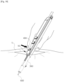
FIGS. 9 and10 are views schematically showing a difference in insertion depth in a skin tissue, depending on the position of the stretching unit in the electrosurgical device having an easily adjustable length according to an embodiment of the present invention. - Referring to
FIG. 9 first, an operator holds thebody 100 and inserts theblade 600 through incised skin S. In this process, since the stretchingmember 300 has been moved backward, the lengths of thebody 100 and theblade 600 is too small, so theblade 600 cannot be pushed deep into the incised skin S. - Next, referring to
FIG. 10 , the operator holding thebody 100 moves the stretchingmember 300 forward in thesecond receiving portion 120a by pressing down thebutton portion 406 of thebutton stopper 400. In this process, the operator holds with his/her hand and moves forward the stretchingmember 300. Accordingly, theblade 600 is moved forward together with the stretchingmember 300. Then, when the operator takes the hand off thebutton portion 406 of thebutton stopper 400, the lockingportion 404 of thebutton stopper 400 is locked to the locking steps 302 of the stretchingmember 300, whereby the stretchingmember 300 is naturally locked. - As described above, by unlocking the stretching
member 300 in one-touch button type that pressing down thebutton portion 406 once, the stretchingmember 300 combined with theblade 600 can be easily moved in thebody 100, and accordingly, the entire length can be easily adjusted. Accordingly, an operator can easily insert theblade 600 through incised skin of a patient. - Although the present invention was described in detail with reference to the embodiment, the present invention is not limited to the embodiment, it is apparent to those skilled in the art that the present invention may be changed and modified in various ways within the scope of the present invention. The invention is defined in independent claim 1, further embodiments are defined by the dependent claims.
Claims (10)
- An electrosurgical device (50) having an easily adjustable length, the electrosurgical device (50) comprising:a body (100) elongated in a longitudinal direction and having a space longitudinally defined therein;an operation unit (200) having an operation member (210) with a first side disposed in the space and a second side exposed over the space, a substrate (220) disposed in the space and electrically connected with the operation member (210), and a contact member (230) elongated in the space with a top thereof in electrical contact with the substrate (220);a stretching member (300) being slidable in the space and having a plurality of locking steps (302) longitudinally formed on a top thereof;a button stopper (400) supported and moved on the body (100) to or not to be locked to the locking steps (302);a contact guide (500) with a first end disposed in the stretching member (300) and a second end extending toward the contact member; anda blade (600) coupled to the first end of the contact guide (500) and extending out of the stretching member (300),wherein when the stretching member (300) is moved in the space without the button stopper (400) locked to the locking steps (302), the contact guide (500) slides along the contact member (230) in contact with the contact member (230).
- The electrosurgical device (50) of claim 1, wherein the button stopper (400) has a rotation guide (402) rotatably disposed in the space of the body (100), a button portion (406) extending upward to be exposed over the space at a first side of the rotation guide (402), and a locking portion (404) extending at a second side of the rotation guide (402) to be locked to the locking steps (302), and
when the button portion (406) is pressed down, the locking portion (404) is lifted not to be locked to the locking steps (302), and when the button portion (406) is pressed up, the locking portion (404) is moved down to be locked to the locking steps (302). - The electrosurgical device (50) of claim 2, further comprising an elastic member (460) supported to face a bottom of the button portion (406) in the space to press up the button portion (406).
- The electrosurgical device (50) of claim 2, further comprising an elastic member (450) supported to face a top of the locking portion (404) in the space to press down the locking portion (404) such that the button portion (406) is pressed up.
- The electrosurgical device (50) of claim 3 or 4, wherein the elastic member (450; 460) includes any one selected from a plate spring, a coil spring, and a rubber member.
- The electrosurgical device (50) of claim 4, wherein a first guide (405) protrudes upward from the locking portion (404),a second guide (114) is formed on an inner side of the body (100) at a position facing the first guide, andthe elastic member (450) is disposed between the first guide and the second guide.
- The electrosurgical device (50) of claim 1, wherein the space includes a first receiving portion (110a) disposed over a top plate (122) longitudinally elongated therein and a second receiving portion (120a) disposed under the top plate (122) with longitudinal front and rear thereof open,the operation member (210) of the operation unit (200) and the substrate (220) are disposed in the first receiving portion (110a), the contact member (230) of the operation unit (200) is elongated in the second receiving portion (120a) and electrically connected with the substrate (220) through the top plate (122),the stretching member (300) is disposed in the second receiving portion (120a) under the contact member (230) to be movable forward out of the second receiving portion (120a) or into the second receiving portion (120a), and has a suction passage (300a) longitudinally formed therein,the contact guide (500) has a first end disposed in the suction passage (300a) and a second end extending toward the contact member (230) through the suction passage (300a),the button stopper (400) is rotatably supported on the top plate (122) with a first side exposed out of the body (100) and a second side disposed to or not to be locked to the locking steps (302) through the top plate (122), andthe blade (600) is coupled to the first end of the contact guide (500) and extends out of the suction passage (300a).
- The electrosurgical device (50) of claim 7, wherein the contact guide (500) has a front end extending toward a front of the suction passage (300a) where the blade (600) is disposed, a rear end extending to a rear of the suction passage (300a), and a contact terminal (504) bent toward the contact member (230) at the rear, and
the contact terminal (504) is configured to be in contact with the contact member (230), so power applied to the contact member (230) is transmitted to the blade (600) connected with the contact guide (500). - The electrosurgical device (50) of claim 8, wherein a cut guide (304) is formed by cutting forward a rear, where the contact terminal is disposed, of the stretching member (300), and the contact terminal is guided in the cut guide (304).
- The electrosurgical device (50) of claim 7, wherein a coupling guide (310) is inserted in a front, which faces the blade (600), of the suction passage (300a), and
the blade (600) is fitted in a first end of the coupling guide (310), the contact guide (500) is fitted in a second end of the coupling guide (310), and the blade (600) and the coupling guide (310) are electrically connected to each other.
Applications Claiming Priority (2)
| Application Number | Priority Date | Filing Date | Title |
|---|---|---|---|
| KR1020150174736A KR101801027B1 (en) | 2015-11-20 | 2015-12-09 | Electro-surgical apparatus |
| PCT/KR2016/000543 WO2017099291A1 (en) | 2015-12-09 | 2016-01-19 | Electrosurgical device having easily adjustable length |
Publications (3)
| Publication Number | Publication Date |
|---|---|
| EP3388009A1 EP3388009A1 (en) | 2018-10-17 |
| EP3388009A4 EP3388009A4 (en) | 2019-07-31 |
| EP3388009B1 true EP3388009B1 (en) | 2025-04-23 |
Family
ID=59013419
Family Applications (1)
| Application Number | Title | Priority Date | Filing Date |
|---|---|---|---|
| EP16873157.8A Active EP3388009B1 (en) | 2015-12-09 | 2016-01-19 | Electrosurgical device having easily adjustable length |
Country Status (7)
| Country | Link |
|---|---|
| US (1) | US11419669B2 (en) |
| EP (1) | EP3388009B1 (en) |
| JP (1) | JP6609876B2 (en) |
| KR (1) | KR101801027B1 (en) |
| CN (1) | CN108366821B (en) |
| ES (1) | ES3024509T3 (en) |
| WO (1) | WO2017099291A1 (en) |
Families Citing this family (18)
| Publication number | Priority date | Publication date | Assignee | Title |
|---|---|---|---|---|
| US11992261B2 (en) * | 2017-05-16 | 2024-05-28 | Megadyne Medical Products, Inc. | Locking mechanism and sliding conductor for extendable shaft |
| KR102070891B1 (en) * | 2018-03-08 | 2020-01-29 | 재단법인 대구경북과학기술원 | Micro Surgical Instrument |
| KR102112244B1 (en) * | 2018-03-21 | 2020-05-19 | (주)메덴 | Medical blade |
| US11399883B2 (en) | 2018-08-20 | 2022-08-02 | Volta Innovations, S. De R.L. De C.V. | Cauterizing device and system |
| US11432866B2 (en) * | 2019-02-04 | 2022-09-06 | Ik Ro Park | Electrosurgery smoke suction apparatus |
| KR102254266B1 (en) * | 2019-02-11 | 2021-05-21 | 강호상 | Electrosurgical pencil |
| USD905854S1 (en) * | 2019-06-07 | 2020-12-22 | Volta Innovations, S. De R.L. De C.V. | Cauterizing device |
| CN110179534A (en) * | 2019-06-27 | 2019-08-30 | 安徽邵氏华艾生物医疗电子科技有限公司 | A kind of nano-knife ablating electrode |
| KR102281144B1 (en) * | 2019-08-30 | 2021-07-22 | 인제대학교 산학협력단 | Medical biomaterial unit and Applicator for attaching the mdical biomaterial unit |
| KR102419563B1 (en) * | 2020-05-06 | 2022-07-11 | 주식회사 바이오유닛 | Bipolar electrocautery device for ablation using high frequency |
| US11911088B2 (en) * | 2020-09-09 | 2024-02-27 | Bio-Protech Inc. | Smoke pencil with swivel device |
| WO2022055000A1 (en) * | 2020-09-14 | 2022-03-17 | Ik Ro Park | Smoke pencil with swivel device |
| KR102577647B1 (en) * | 2021-10-28 | 2023-09-13 | 주식회사 두리엔 | Smoke suction unit for electrosurgical pencil |
| CN113876415B (en) * | 2021-11-09 | 2025-12-19 | 默华医疗科技(广州)有限公司 | Ablation electrode capable of adjusting button position and ablation electrode system comprising same |
| CN115590610B (en) * | 2022-09-28 | 2025-06-27 | 默华医疗科技(湖南)有限公司 | Retractable minimally invasive dissection needle |
| EP4687727A1 (en) * | 2023-03-31 | 2026-02-11 | Covidien LP | Electrosurgical pencil with smoke evacuation and electrode visualization |
| KR20250064402A (en) | 2023-11-02 | 2025-05-09 | 현대자동차주식회사 | Quantum dot-based light sensor device and method of manufacturing the same |
| KR20260049906A (en) * | 2024-10-07 | 2026-04-14 | 주식회사 바이오프로테크 | Electrosurgical Apparatus with Locking Member for Controlling Position of Blade |
Family Cites Families (11)
| Publication number | Priority date | Publication date | Assignee | Title |
|---|---|---|---|---|
| US5693044A (en) * | 1992-12-11 | 1997-12-02 | Cosmescu; Ioan | Telescopic surgical device and method therefor |
| US7112199B2 (en) * | 1996-09-20 | 2006-09-26 | Ioan Cosmescu | Multifunctional telescopic monopolar/bipolar surgical device and method therefore |
| US6197024B1 (en) * | 1999-09-22 | 2001-03-06 | Scott Keith Sullivan | Adjustable electrocautery surgical apparatus |
| US7244257B2 (en) | 2002-11-05 | 2007-07-17 | Sherwood Services Ag | Electrosurgical pencil having a single button variable control |
| EP1902682B1 (en) * | 2003-11-14 | 2017-01-11 | Lina Medical ApS | Length adjustable electro-surgical pencil with suction means |
| US9907621B2 (en) * | 2008-11-14 | 2018-03-06 | Prash Jayaraj | Surgical pencil |
| KR20110002463U (en) | 2009-09-03 | 2011-03-09 | 양린산-치 | Electric operation pen with suction function |
| CA2834591C (en) * | 2011-05-19 | 2019-09-10 | Cimpax Aps | An electrosurgical pencil, a kit of parts comprising an electrosurgical pencil, and a method of providing an electrosurgical pencil |
| AU2012388657B2 (en) * | 2012-08-28 | 2017-09-07 | Covidien Lp | Adjustable electrosurgical pencil |
| KR101586813B1 (en) | 2013-06-10 | 2016-01-20 | 주식회사 바이오프로테크 | Electro-surgical apparatus |
| KR101576730B1 (en) | 2014-03-31 | 2015-12-10 | 주식회사 리메드 | Handpiece For Electrical Surgical Apparatus And, Electrical Surgical Apparatus Comprising Thereof |
-
2015
- 2015-12-09 KR KR1020150174736A patent/KR101801027B1/en active Active
-
2016
- 2016-01-19 US US15/755,203 patent/US11419669B2/en active Active
- 2016-01-19 WO PCT/KR2016/000543 patent/WO2017099291A1/en not_active Ceased
- 2016-01-19 EP EP16873157.8A patent/EP3388009B1/en active Active
- 2016-01-19 JP JP2018550309A patent/JP6609876B2/en active Active
- 2016-01-19 CN CN201680071940.7A patent/CN108366821B/en active Active
- 2016-01-19 ES ES16873157T patent/ES3024509T3/en active Active
Also Published As
| Publication number | Publication date |
|---|---|
| JP6609876B2 (en) | 2019-11-27 |
| EP3388009A1 (en) | 2018-10-17 |
| CN108366821A (en) | 2018-08-03 |
| WO2017099291A1 (en) | 2017-06-15 |
| KR101801027B1 (en) | 2017-11-27 |
| KR20170059354A (en) | 2017-05-30 |
| JP2019500189A (en) | 2019-01-10 |
| US11419669B2 (en) | 2022-08-23 |
| US20180243026A1 (en) | 2018-08-30 |
| EP3388009A4 (en) | 2019-07-31 |
| ES3024509T3 (en) | 2025-06-04 |
| CN108366821B (en) | 2021-09-17 |
Similar Documents
| Publication | Publication Date | Title |
|---|---|---|
| US11419669B2 (en) | Electrosurgical device having easily adjustable length | |
| EP3335656B1 (en) | Multi-mode combination electrosurgical device | |
| US6197024B1 (en) | Adjustable electrocautery surgical apparatus | |
| EP1852080B1 (en) | Soft tissue RF transection and resection device | |
| US6896672B1 (en) | Methods for electrosurgical incisions on external skin surfaces | |
| US6117109A (en) | Systems and methods for electrosurgical incisions on external skin surfaces | |
| US6364879B1 (en) | Electrosurgical cutting instrument | |
| US7935109B2 (en) | Multifunctional telescopic monopolar/bipolar surgical device and method thereof | |
| EP1041933B1 (en) | Systems for electrosurgical treatment of the skin | |
| CA2351649C (en) | Multifunctional telescopic electrosurgical instrument, and method therefor | |
| CA2569431C (en) | Auto-safety shut-off for energy based devices | |
| CN105246424A (en) | Combined Electrosurgical Devices | |
| US20090076412A1 (en) | Apparatus and Methods for Obtaining a Sample of Tissue | |
| JP7152031B2 (en) | Telescopic Electrosurgical Pencil Used in ESU Monopolar and Bipolar Modes | |
| JP2022119896A (en) | Superpolar electrosurgical blade assembly and superpolar electrosurgical pencil with argon beam capability | |
| EP3730105B1 (en) | Ophthalmic surgical apparatus | |
| CA2524529C (en) | Multifunctional electrosurgical instrument, and method therefor | |
| KR102254266B1 (en) | Electrosurgical pencil | |
| JP2019532770A (en) | Attachment for electrosurgical system | |
| CN222237800U (en) | High-frequency electric knife tip protection device and high-frequency electric knife | |
| US20250127557A1 (en) | Monopolar handpiece for electrosurgery | |
| KR20260049906A (en) | Electrosurgical Apparatus with Locking Member for Controlling Position of Blade |
Legal Events
| Date | Code | Title | Description |
|---|---|---|---|
| STAA | Information on the status of an ep patent application or granted ep patent |
Free format text: STATUS: THE INTERNATIONAL PUBLICATION HAS BEEN MADE |
|
| PUAI | Public reference made under article 153(3) epc to a published international application that has entered the european phase |
Free format text: ORIGINAL CODE: 0009012 |
|
| STAA | Information on the status of an ep patent application or granted ep patent |
Free format text: STATUS: REQUEST FOR EXAMINATION WAS MADE |
|
| 17P | Request for examination filed |
Effective date: 20180709 |
|
| AK | Designated contracting states |
Kind code of ref document: A1 Designated state(s): AL AT BE BG CH CY CZ DE DK EE ES FI FR GB GR HR HU IE IS IT LI LT LU LV MC MK MT NL NO PL PT RO RS SE SI SK SM TR |
|
| AX | Request for extension of the european patent |
Extension state: BA ME |
|
| DAV | Request for validation of the european patent (deleted) | ||
| DAX | Request for extension of the european patent (deleted) | ||
| A4 | Supplementary search report drawn up and despatched |
Effective date: 20190701 |
|
| RIC1 | Information provided on ipc code assigned before grant |
Ipc: A61B 17/00 20060101ALI20190625BHEP Ipc: A61B 18/12 20060101AFI20190625BHEP Ipc: A61B 18/14 20060101ALI20190625BHEP Ipc: A61B 18/00 20060101ALI20190625BHEP |
|
| RAP1 | Party data changed (applicant data changed or rights of an application transferred) |
Owner name: BIO-PROTECH INC. |
|
| RIN1 | Information on inventor provided before grant (corrected) |
Inventor name: PARK, IK RO |
|
| GRAP | Despatch of communication of intention to grant a patent |
Free format text: ORIGINAL CODE: EPIDOSNIGR1 |
|
| STAA | Information on the status of an ep patent application or granted ep patent |
Free format text: STATUS: GRANT OF PATENT IS INTENDED |
|
| INTG | Intention to grant announced |
Effective date: 20241120 |
|
| RIN1 | Information on inventor provided before grant (corrected) |
Inventor name: PARK, IK RO |
|
| GRAS | Grant fee paid |
Free format text: ORIGINAL CODE: EPIDOSNIGR3 |
|
| GRAA | (expected) grant |
Free format text: ORIGINAL CODE: 0009210 |
|
| STAA | Information on the status of an ep patent application or granted ep patent |
Free format text: STATUS: THE PATENT HAS BEEN GRANTED |
|
| AK | Designated contracting states |
Kind code of ref document: B1 Designated state(s): AL AT BE BG CH CY CZ DE DK EE ES FI FR GB GR HR HU IE IS IT LI LT LU LV MC MK MT NL NO PL PT RO RS SE SI SK SM TR |
|
| REG | Reference to a national code |
Ref country code: GB Ref legal event code: FG4D |
|
| REG | Reference to a national code |
Ref country code: CH Ref legal event code: EP |
|
| REG | Reference to a national code |
Ref country code: DE Ref legal event code: R096 Ref document number: 602016092022 Country of ref document: DE |
|
| REG | Reference to a national code |
Ref country code: IE Ref legal event code: FG4D |
|
| REG | Reference to a national code |
Ref country code: ES Ref legal event code: FG2A Ref document number: 3024509 Country of ref document: ES Kind code of ref document: T3 Effective date: 20250604 |
|
| REG | Reference to a national code |
Ref country code: NL Ref legal event code: MP Effective date: 20250423 |
|
| PG25 | Lapsed in a contracting state [announced via postgrant information from national office to epo] |
Ref country code: NL Free format text: LAPSE BECAUSE OF FAILURE TO SUBMIT A TRANSLATION OF THE DESCRIPTION OR TO PAY THE FEE WITHIN THE PRESCRIBED TIME-LIMIT Effective date: 20250423 |
|
| REG | Reference to a national code |
Ref country code: AT Ref legal event code: MK05 Ref document number: 1787034 Country of ref document: AT Kind code of ref document: T Effective date: 20250423 |
|
| PG25 | Lapsed in a contracting state [announced via postgrant information from national office to epo] |
Ref country code: PT Free format text: LAPSE BECAUSE OF FAILURE TO SUBMIT A TRANSLATION OF THE DESCRIPTION OR TO PAY THE FEE WITHIN THE PRESCRIBED TIME-LIMIT Effective date: 20250825 Ref country code: FI Free format text: LAPSE BECAUSE OF FAILURE TO SUBMIT A TRANSLATION OF THE DESCRIPTION OR TO PAY THE FEE WITHIN THE PRESCRIBED TIME-LIMIT Effective date: 20250423 |
|
| REG | Reference to a national code |
Ref country code: LT Ref legal event code: MG9D |
|
| PG25 | Lapsed in a contracting state [announced via postgrant information from national office to epo] |
Ref country code: NO Free format text: LAPSE BECAUSE OF FAILURE TO SUBMIT A TRANSLATION OF THE DESCRIPTION OR TO PAY THE FEE WITHIN THE PRESCRIBED TIME-LIMIT Effective date: 20250723 Ref country code: GR Free format text: LAPSE BECAUSE OF FAILURE TO SUBMIT A TRANSLATION OF THE DESCRIPTION OR TO PAY THE FEE WITHIN THE PRESCRIBED TIME-LIMIT Effective date: 20250724 |
|
| PG25 | Lapsed in a contracting state [announced via postgrant information from national office to epo] |
Ref country code: PL Free format text: LAPSE BECAUSE OF FAILURE TO SUBMIT A TRANSLATION OF THE DESCRIPTION OR TO PAY THE FEE WITHIN THE PRESCRIBED TIME-LIMIT Effective date: 20250423 |
|
| PG25 | Lapsed in a contracting state [announced via postgrant information from national office to epo] |
Ref country code: BG Free format text: LAPSE BECAUSE OF FAILURE TO SUBMIT A TRANSLATION OF THE DESCRIPTION OR TO PAY THE FEE WITHIN THE PRESCRIBED TIME-LIMIT Effective date: 20250423 |
|
| PG25 | Lapsed in a contracting state [announced via postgrant information from national office to epo] |
Ref country code: HR Free format text: LAPSE BECAUSE OF FAILURE TO SUBMIT A TRANSLATION OF THE DESCRIPTION OR TO PAY THE FEE WITHIN THE PRESCRIBED TIME-LIMIT Effective date: 20250423 |
|
| PG25 | Lapsed in a contracting state [announced via postgrant information from national office to epo] |
Ref country code: AT Free format text: LAPSE BECAUSE OF FAILURE TO SUBMIT A TRANSLATION OF THE DESCRIPTION OR TO PAY THE FEE WITHIN THE PRESCRIBED TIME-LIMIT Effective date: 20250423 |
|
| PG25 | Lapsed in a contracting state [announced via postgrant information from national office to epo] |
Ref country code: RS Free format text: LAPSE BECAUSE OF FAILURE TO SUBMIT A TRANSLATION OF THE DESCRIPTION OR TO PAY THE FEE WITHIN THE PRESCRIBED TIME-LIMIT Effective date: 20250723 |
|
| PG25 | Lapsed in a contracting state [announced via postgrant information from national office to epo] |
Ref country code: IS Free format text: LAPSE BECAUSE OF FAILURE TO SUBMIT A TRANSLATION OF THE DESCRIPTION OR TO PAY THE FEE WITHIN THE PRESCRIBED TIME-LIMIT Effective date: 20250823 |
|
| PG25 | Lapsed in a contracting state [announced via postgrant information from national office to epo] |
Ref country code: LV Free format text: LAPSE BECAUSE OF FAILURE TO SUBMIT A TRANSLATION OF THE DESCRIPTION OR TO PAY THE FEE WITHIN THE PRESCRIBED TIME-LIMIT Effective date: 20250423 |
|
| PG25 | Lapsed in a contracting state [announced via postgrant information from national office to epo] |
Ref country code: SM Free format text: LAPSE BECAUSE OF FAILURE TO SUBMIT A TRANSLATION OF THE DESCRIPTION OR TO PAY THE FEE WITHIN THE PRESCRIBED TIME-LIMIT Effective date: 20250423 Ref country code: DK Free format text: LAPSE BECAUSE OF FAILURE TO SUBMIT A TRANSLATION OF THE DESCRIPTION OR TO PAY THE FEE WITHIN THE PRESCRIBED TIME-LIMIT Effective date: 20250423 |
|
| PG25 | Lapsed in a contracting state [announced via postgrant information from national office to epo] |
Ref country code: CZ Free format text: LAPSE BECAUSE OF FAILURE TO SUBMIT A TRANSLATION OF THE DESCRIPTION OR TO PAY THE FEE WITHIN THE PRESCRIBED TIME-LIMIT Effective date: 20250423 |
|
| PG25 | Lapsed in a contracting state [announced via postgrant information from national office to epo] |
Ref country code: EE Free format text: LAPSE BECAUSE OF FAILURE TO SUBMIT A TRANSLATION OF THE DESCRIPTION OR TO PAY THE FEE WITHIN THE PRESCRIBED TIME-LIMIT Effective date: 20250423 |
|
| REG | Reference to a national code |
Ref country code: DE Ref legal event code: R097 Ref document number: 602016092022 Country of ref document: DE |
|
| PG25 | Lapsed in a contracting state [announced via postgrant information from national office to epo] |
Ref country code: SK Free format text: LAPSE BECAUSE OF FAILURE TO SUBMIT A TRANSLATION OF THE DESCRIPTION OR TO PAY THE FEE WITHIN THE PRESCRIBED TIME-LIMIT Effective date: 20250423 Ref country code: RO Free format text: LAPSE BECAUSE OF FAILURE TO SUBMIT A TRANSLATION OF THE DESCRIPTION OR TO PAY THE FEE WITHIN THE PRESCRIBED TIME-LIMIT Effective date: 20250423 |
|
| PG25 | Lapsed in a contracting state [announced via postgrant information from national office to epo] |
Ref country code: IT Free format text: LAPSE BECAUSE OF FAILURE TO SUBMIT A TRANSLATION OF THE DESCRIPTION OR TO PAY THE FEE WITHIN THE PRESCRIBED TIME-LIMIT Effective date: 20250423 |
|
| PLBE | No opposition filed within time limit |
Free format text: ORIGINAL CODE: 0009261 |
|
| STAA | Information on the status of an ep patent application or granted ep patent |
Free format text: STATUS: NO OPPOSITION FILED WITHIN TIME LIMIT |
|
| REG | Reference to a national code |
Ref country code: CH Ref legal event code: L10 Free format text: ST27 STATUS EVENT CODE: U-0-0-L10-L00 (AS PROVIDED BY THE NATIONAL OFFICE) Effective date: 20260304 |
|
| 26N | No opposition filed |
Effective date: 20260126 |
|
| PGFP | Annual fee paid to national office [announced via postgrant information from national office to epo] |
Ref country code: GB Payment date: 20260122 Year of fee payment: 11 |
|
| PGFP | Annual fee paid to national office [announced via postgrant information from national office to epo] |
Ref country code: ES Payment date: 20260217 Year of fee payment: 11 |
|
| PGFP | Annual fee paid to national office [announced via postgrant information from national office to epo] |
Ref country code: DE Payment date: 20260131 Year of fee payment: 11 |
|
| PGFP | Annual fee paid to national office [announced via postgrant information from national office to epo] |
Ref country code: FR Payment date: 20260127 Year of fee payment: 11 |