EP3387956A1 - Screw-shaft based lever actuator mechanism for chair function - Google Patents
Screw-shaft based lever actuator mechanism for chair function Download PDFInfo
- Publication number
- EP3387956A1 EP3387956A1 EP17166198.6A EP17166198A EP3387956A1 EP 3387956 A1 EP3387956 A1 EP 3387956A1 EP 17166198 A EP17166198 A EP 17166198A EP 3387956 A1 EP3387956 A1 EP 3387956A1
- Authority
- EP
- European Patent Office
- Prior art keywords
- chair
- shuttle
- actuator mechanism
- screw shaft
- linear motion
- Prior art date
- Legal status (The legal status is an assumption and is not a legal conclusion. Google has not performed a legal analysis and makes no representation as to the accuracy of the status listed.)
- Granted
Links
Images


Classifications
-
- A—HUMAN NECESSITIES
- A47—FURNITURE; DOMESTIC ARTICLES OR APPLIANCES; COFFEE MILLS; SPICE MILLS; SUCTION CLEANERS IN GENERAL
- A47C—CHAIRS; SOFAS; BEDS
- A47C1/00—Chairs adapted for special purposes
- A47C1/02—Reclining or easy chairs
- A47C1/022—Reclining or easy chairs having independently-adjustable supporting parts
-
- A—HUMAN NECESSITIES
- A47—FURNITURE; DOMESTIC ARTICLES OR APPLIANCES; COFFEE MILLS; SPICE MILLS; SUCTION CLEANERS IN GENERAL
- A47C—CHAIRS; SOFAS; BEDS
- A47C7/00—Parts, details, or accessories of chairs or stools
-
- A—HUMAN NECESSITIES
- A47—FURNITURE; DOMESTIC ARTICLES OR APPLIANCES; COFFEE MILLS; SPICE MILLS; SUCTION CLEANERS IN GENERAL
- A47C—CHAIRS; SOFAS; BEDS
- A47C3/00—Chairs characterised by structural features; Chairs or stools with rotatable or vertically-adjustable seats
- A47C3/20—Chairs or stools with vertically-adjustable seats
-
- A—HUMAN NECESSITIES
- A47—FURNITURE; DOMESTIC ARTICLES OR APPLIANCES; COFFEE MILLS; SPICE MILLS; SUCTION CLEANERS IN GENERAL
- A47C—CHAIRS; SOFAS; BEDS
- A47C3/00—Chairs characterised by structural features; Chairs or stools with rotatable or vertically-adjustable seats
- A47C3/20—Chairs or stools with vertically-adjustable seats
- A47C3/34—Chairs or stools with vertically-adjustable seats with pins coacting with holes
-
- A—HUMAN NECESSITIES
- A47—FURNITURE; DOMESTIC ARTICLES OR APPLIANCES; COFFEE MILLS; SPICE MILLS; SUCTION CLEANERS IN GENERAL
- A47C—CHAIRS; SOFAS; BEDS
- A47C7/00—Parts, details, or accessories of chairs or stools
- A47C7/36—Supports for the head or the back
- A47C7/40—Supports for the head or the back for the back
-
- F—MECHANICAL ENGINEERING; LIGHTING; HEATING; WEAPONS; BLASTING
- F16—ENGINEERING ELEMENTS AND UNITS; GENERAL MEASURES FOR PRODUCING AND MAINTAINING EFFECTIVE FUNCTIONING OF MACHINES OR INSTALLATIONS; THERMAL INSULATION IN GENERAL
- F16H—GEARING
- F16H25/00—Gearings comprising primarily only cams, cam-followers and screw-and-nut mechanisms
- F16H25/18—Gearings comprising primarily only cams, cam-followers and screw-and-nut mechanisms for conveying or interconverting oscillating or reciprocating motions
- F16H25/20—Screw mechanisms
- F16H25/24—Elements essential to such mechanisms, e.g. screws, nuts
- F16H25/2409—Elements essential to such mechanisms, e.g. screws, nuts one of the threads being replaced by elements specially formed for engaging the screw or nut, e.g. pins, racks, toothed belts
Definitions
- the invention relates to an actuator mechanism for a chair and to a chair.
- the invention relates in particular to an actuator mechanism for integration in a chair seat.
- chairs are nowadays provided with one or more functions that can be actuated by a person sitting on the chair.
- Such functions may for example include adjustment of a height of the chair, adjustment of a tilt angle of a seat part of the chair, adjustment of a tilt angle of a back part of the chair, or locking or releasing a tilt movement of the chair.
- one or more of such functions may be provided in an office chair.
- the chair needs to be provided with one or more actuating elements, such as levers or knobs.
- actuating elements such as levers or knobs.
- these are preferably arranged at locations which are easily accessible to a person sitting on the chair, e.g., below the seat part of the chair.
- increasing the size of seat components or adding additional seat components to accommodate the actuator mechanism might not be desirable from a design or cost perspective.
- the present invention provides an actuator mechanism according to claim 1 and a chair according to claim 15.
- the dependent claims define further embodiments.
- an actuator mechanism has the purpose of being used in a chair, for controlling a function of the chair. Examples of such function are adjustment of a height of a chair seat, adjustment of a tilt angle of a chair seat of the chair, adjustment of a tilt angle of a back of the chair, shifting of a seat of the chair with respect to a back of the chair, or locking or releasing a tilt movement of the chair.
- the actuator mechanism comprises a screw shaft having an external thread.
- the actuator mechanism comprises a lever configured to rotate the screw shaft and a shuttle engaged with the external thread of the screw shaft. By the engagement of the shuttle with the external thread of the screw shaft, rotation of the screw shaft caused by the lever translates into a linear motion of the shuttle along the screw shaft.
- the function of the chair is controlled by the linear motion of the shuttle.
- the actuator mechanism can be built with a compact configuration which is substantially confined to a plane including the direction of the linear motion of the shuttle. Further, also forces acting within the actuator mechanism can be confined to a plane including the direction of the linear motion of the shuttle, which facilitates building the actuator mechanism with sufficient mechanical strength.
- the actuator mechanism could be integrated in the chair seat, using the space provided within the horizontal plane of the chair seat.
- the lever could be arranged at the edge of the chair seat, so that it can be easily reached and operated by a person sitting on the chair.
- the screw shaft could then be arranged in parallel to the edge of the chair seat, which means that the lever can be conveniently operated by an upward pulling action.
- the actuator mechanism further comprises a spring arranged to be tensioned by the linear motion of the shuttle. By tension in the spring by the linear motion of the shuttle, a force required to operate the lever can be adjusted to a desired level.
- the actuator mechanism further comprises a Bowden cable coupled to the shuttle and configured to control said function of the chair.
- a Bowden cable coupled to the shuttle and configured to control said function of the chair.
- the actuator mechanism could also comprise a linkage mechanism configured to control the function of the chair.
- a mechanism for implementing the function of the chair could be located in the vicinity of the actuator mechanism and this mechanism and the actuator mechanism could be coupled directly by the linkage mechanism.
- the actuator mechanism comprises a further screw shaft having an external thread, a further lever configured to rotate the further screw shaft; and a further shuttle engaged with the external thread of the further screw shaft.
- rotation of the further screw shaft caused by the further lever translates into a linear motion of the further shuttle along the further screw shaft, and a further function of the chair can be controlled by the linear motion of the further shuttle.
- the actuator mechanism can be enhanced to support multiple functions of the chair.
- a compact configuration of the actuator mechanism may be maintained because both screw shafts may be arranged in the same plane, e.g., parallel to each other.
- both screw shafts could be arranged in parallel to an edge of the chair seat.
- the external thread of the screw shaft has a first pitch and the external thread of the further screw shaft has a second pitch which is higher than the first pitch.
- different pitches on the screw shafts may be used to compensate for different ranges of linear motion required to control different functions of the chair.
- control of the above-mentioned function of the chair may require a first range of said linear motion of the shuttle, while control of the above-mentioned further function of the chair requires a second range of the linear motion of the further shuttle, the second range being higher than the first range. This may be compensated for by making the second pitch higher than the first pitch.
- a range of motion of the lever which causes the first range of linear motion of the shuttle may be equal to a range of motion of the further lever which causes the second range of linear motion of the further shuttle. This is desirable from the perspective of user experience, because control of different functions of the chair can be achieved by levers having similar characteristics.
- the actuator mechanism having the screw shaft and the further screw shaft further comprises a first spring arranged to be tensioned by said linear motion of the shuttle and a second spring arranged to be tensioned by said linear motion of the further shuttle.
- the first spring may have a higher spring constant than the second spring. In this way, a force required to operate the lever and a force required to operate the further lever can be adjusted with respect to each other.
- a force required for moving the lever to cause the first range of linear motion of the shuttle may be adjusted to be equal to a force required for moving the further lever to cause the second range of linear motion of the further shuttle. This is desirable from the perspective of user experience, because control of different functions of the chair can be achieved by levers having similar characteristics.
- the actuator mechanism further comprises a support structure on which the screw shaft, the lever, and the shuttle are supported.
- the support structure may be different from an outer shell of the chair seat.
- the support structure could be attached to the outer shell of the chair seat by screw attachment or gluing.
- the support structures are molded as part of the outer shell, which may adversely affect the appearance of the outer shell, because typically even structures which are arranged on the interior side of the outer shell will be visible due to "sinking" of the plastic material in the molding process.
- a chair is provided, e.g., an office chair.
- the chair has one or more functions, e.g., adjustment of a height of the chair, adjustment of a tilt angle of a seat of the chair, adjustment of a tilt angle of a back of the chair, shifting of a seat of the chair with respect to a back of the chair, or locking or releasing a tilt movement of the chair.
- the chair comprises a chair seat and at least one actuator mechanism as described above.
- the at least one actuator mechanism is integrated the chair seat.
- the at least one actuator mechanism is used for controlling the function(s) of the chair.
- the chair may comprise multiple actuator mechanisms as described above, and/or one or more actuator mechanisms having multiple levers as described above.
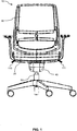
- Fig. 1 shows a chair 10 according to an embodiment.
- the chair 10 is illustrated to be an office-type chair and has a chair seat 20, a chair back 30 and components to interconnect the chair seat 20 with the chair back 30.
- the chair 10 also includes a base assembly with a pedestal column 50, support legs extending radially from the pedestal column 50, and castors arranged on the outer ends of the support legs.
- a mechanism 40 is arranged on the pedestal column 50.
- the mechanism implements a number of functions of the chair 10, e.g., adjustment of a height of the chair 10, adjustment of a tilt angle of the chair seat 20 with respect to the pedestal column and/or with respect to the chair back 30, adjustment of a tilt angle of the chair back 30 with respect to the pedestal column 50 and/or with respect to the chair seat 20 of, shifting of the chair seat 20 with respect to the chair back 30, or locking or releasing a tilt movement of the chair 10.
- This tilt movement may for example involve concurrent tilting of the chair seat 20 and the chair back 30 in response to rocking movements of a person sitting on the chair 10.
- the adjustment of the height of the chair seat 20 may involve telescoping of the pedestal column, and this telescoping may be controlled by a gas cylinder which is pressurized when lowering the chair seat 20 and depressurized when lifting the chair seat 20.
- the chair is provided with actuating levers 110, 111 which are arranged at an outer edge of the chair seat 20. Accordingly, the actuating levers 110, 111 can be easily reached by a person sitting on the chair 10.
- the mechanism 40 may release a lock of the telescoping movement of the pedestal column 50, thereby enabling the person sitting on the chair 10 to adjust the heat of the chair seat 20.
- the mechanism 40 locks the telescoping movement of the pedestal collagen 50 in the currently set position.
- pulling the actuating lever 111 upward the mechanism 40 could release a lock of the tilt movement of the chair 10.
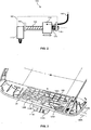
- the actuating lever 110 and the actuating lever 111 are each part of a corresponding actuating mechanism which is integrated in the chair seat 20. With reference to the actuating lever 110, structures and operation of such actuating mechanism 100 are schematically illustrated in Fig. 2 . However, it is noted that a similar actuating mechanism could also be used for the actuating lever 111 or any other actuating lever of the chair 10.
- the actuating mechanism 100 includes a screw shaft 120.
- the lever 110 is connected to the screw shaft 120 so that the screw shaft 120 is rotated about a longitudinal rotation axis (illustrated by a dotted line) when the lever 110 is operated, as illustrated by a solid arrow.
- the screw shaft 120 has a helix-shaped external thread.
- a shuttle 130 which is supported to be movable in a direction along the screw shaft 120, is engaged with the external thread of the screw shaft 120.
- the shuttle 130 could be provided with an internal thread which matches the external thread of the screw shaft 120.
- a rotation of the screw shaft 120, caused by operation of the lever 110 translates into a linear motion of the shuttle 130 along the screw shaft 120, as illustrated by an open arrow.
- the range of rotation of the screw shaft 120 caused by operation of the lever 110 is between 30° and 180°.
- the corresponding linear displacement of the shuttle 130 may be in the range of 10 - 20 mm.
- the linear motion of the shuttle 130 is used for mechanically controlling a function of the chair.
- the actuator mechanism 100 includes a Bowden cable 140.
- the Bowden cable 140 has the purpose of transmitting the falls associated with the linear motion of the shuttle 130 to the remotely located mechanism 40, which implements the function of the chair 10 to be controlled by the lever 110.
- the Bowden cable 140 may for example extend through the chair seat 20 and through the pedestal column 50, so that it is not visible from the outside.
- a wire of the Bowden cable 140 is coupled to the shuttle 130, while an outer sheath of the Bowden cable 140 is anchored on a support structure 160 of the actuator mechanism 100.
- the support structure 160 includes a first support element 161, which is used for anchoring the outer sheath of the Bowden cable 140.
- the first support element 161 and a second support element 162 of the support structure 160 are used for rotatably supporting the screw shaft 120.
- Additional support structures may be provided as well, e.g., one or more support structures for guiding the linear motion of the shuttle 130.
- the linear motion of the shuttle 130 releases tension in the Bowden cable 140.
- the linear motion of the shuttle 130 could also have the effect of increasing tension in the Bowden cable 140.
- a spring 170 is arranged between the shuttle 130 and the support structure 161.
- the spring 170 is assumed to be a helical compression spring. Accordingly, when the shuttle 130 moves in the illustrated manner toward the support structure 161, the spring 170 is tensioned. The tensioning of the spring 170 provides a resistance against the operation of the lever 110. Further, by selecting the spring 170 with a suitable spring constant, the force required for operating the lever 110 can be adjusted to a desired level, which is different from the force which would be needed for controlling the function of the chair 10. In this way, it can achieved that the lever 110 has a desirable crisp feel of operation. Further, the spring 170 may also provide for restoration of the shuttle 130 and the lever 110, when the lever 110 is released.
- spring 170 in the form of a helical compression spring is merely exemplary, and that other kinds of springs could be used as an alternative or in addition, e.g., other forms of compression springs, such as a gas spring, or an extension spring provided between the support structure 162 and the shuttle 130.
- Fig. 3 shows an example of an actuator mechanism which is based on the principles as explained in connection with Fig. 2 .
- the actuator mechanism includes a first lever 110A and a second lever 110B.
- the actuator mechanism includes a first screw shaft 120A and a second screw shaft 120B, each provided with a helix like external thread.
- a first shuttle 130A is engaged with the first screw shaft 120A, so that a rotation of the first screw shaft 120A causes a linear motion of the first shuttle 130A.
- a second shuttle 130B is engaged with the second screw shaft 120B, so that a rotation of the second screw shaft 120B causes a linear motion of the second shuttle 130B.
- the actuator mechanism of Fig. 3 includes a first spring which is tensioned by the linear motion of the first shuttle 130A, and a second spring which is tensioned by the linear motion of the second shuttle 130B.
- a first Bowden cable 140A is coupled to the first shuttle 130A
- a second Bowden cable 140B is coupled to the second shuttle 130B.
- the elements of the actuator mechanism are supported by a support structure 160, which is attached by screw fixation into the interior of an outer shell of the chair seat 20.
- the outer shell of the chair seat 20 and the support structure 160 are both formed of a molded plastic material. However, since the outer shell of the chair seat 20 and the support structure 160 are molded as separate parts, the presence of the support structure 160 does not adversely affect the appearance of the outer shell of the chair seat 20, e.g., due to sinking of the outer surface.
- the linear motion of the first shuttle 130A is used for mechanically controlling a first function of the chair 10
- the linear motion of the second shuttle 130B is used for mechanically controlling a second function of the chair 10.
- the linear motion of the first shuttle 130A could be used for adjustment of the height of the chair seat 20, whereas the linear motion of the second shuttle 130B could be used for locking or releasing a tilt movement of the chair 10.
- the actuator mechanism of Fig. 3 is configured for operation as explained in connection with Fig. 2 .
- first screw shaft 120A and the second screw shaft 120B are co-linear and arranged in parallel to the outer edge of the chair seat 20. In this way, the multiple levers 110A, 110B and associated components of the actuating mechanism can be accommodated in a space efficient manner.
- Fig. 4A and 4B illustrate operation of the actuator mechanism of Fig. 3 .
- Fig. 4A shows the actuator mechanism in an unactuated state, with both levers 110A, 110B in a rest position.
- Fig. 4B shows the actuator mechanism in an actuated state of the first lever 110A, while the second lever 110B is in its rest position.
- the lever 110A by pulling the lever 110A upward from its rest position, the first screw shaft 120A is rotated, thereby causing a linear motion of the first shuttle 130A and controlling the corresponding function of the chair 10.
- the second lever 110B could be pulled upward, thereby causing a linear motion of the second shuttle 130B and controlling the corresponding function of the chair 10.
- the range of motion of the first shuttle 130A which is required for control of the corresponding function of the chair 10 may be different from the range of motion of the second shuttle 130B which is required for control of the corresponding function of the chair 10.
- the range of motion of the levers 110A, 110B as required for controlling the different functions is substantially the same.
- this may be achieved by selecting the pitches of the pitches of the screw shafts 120A, 120B in such a way that the required range of linear motion of the first shuttle 130A and the required range of linear motion of the second shuttle 130B are obtained by the same range of motion of both levers 110A, 110B.
- the first screw shaft 120A may be provided with a higher pitch than the second screw shaft 120B.
- the first screw shaft 120A may be provided with a lower pitch than the second screw shaft 120B.
- first lever 110A and the second lever 110B may require different forces exerted by the corresponding shuttle 130A, 130B.
- also using different pitches on the first screw shaft 120A and on the second screw shaft 120B may result in different forces being required to move the shuttle 130A, 130B by rotation of the lever 110A, 110B.
- the force which is required for operation of the levers 110A, 110B is substantially the same. In the illustrated actuator mechanism, this may be achieved by selecting the springs which are tensioned by the linear motion of the shuttles 130A, 130B in such a way that the force which is required for operation of the levers 110A, 110B is substantially the same.
- the first spring which is tensioned by the linear motion of the first shuttle 130A, may be selected with a lower spring constant than the second spring, which is tensioned by the linear motion of the second shuttle 130B.
- the first spring may be selected with a higher spring constant than the second spring.
- the actuator mechanism of Fig. 5 is similar to that of Fig. 3 and includes the first lever 110A, the second lever 110B, the first screw shaft 120A, the second screw shaft 120B, the first shuttle 130A, and the second shuttle 130B.
- the actuator mechanism of Fig. 5 includes a first linkage mechanism 150A coupled to the first shuttle 130A, and a second linkage mechanism 150B coupled to the second shuttle 130B.
- the first linkage mechanism 150A is based on an internal lever which is in sliding engagement with a sloped face of the first shuttle 130A.
- the second linkage mechanism 150B is based on an internal lever which is in sliding engagement with a sloped face of the second shuttle 130B.
- the first linkage mechanism 150A may for example be used for operating a mechanism which controls a function for shifting of the chair seat 20 with respect to the chair back 30.
- the second linkage mechanism 150B may for example be used for operating a mechanism which controls tilting of the chair seat 20 with respect to the chair back 30.
- These mechanisms may be implemented within the chair seat 20, in the vicinity of the actuator mechanism, so that direct coupling of the mechanism to the corresponding linkage mechanism is possible.
- the actuator mechanism of Fig. 6 is similar to that of Fig. 3 and includes the first lever 110A, the second lever 110B, the first screw shaft 120A, the second screw shaft 120B, the first shuttle 130A, and the second shuttle 130B.
- the first Bowden cable 140A and the second Bowden cable 140B are not illustrated.
- the levers 110A, 110B, the screw shafts 120A, 120B, and the shuttles 130A, 130B are supported directly on molded parts of the outer shell of the chair seat 20.
- actuator mechanisms and chairs according to embodiments of the invention are not limited to this particular application. Rather, actuator mechanisms as explained above may be employed in a wide variety of chairs. Further, it is noted that the illustrated actuator mechanisms may be modified in various ways. By way of example, the actuator mechanism could also include more than two levers and corresponding screw shafts and shuttles, thereby enabling support of more than two functions of the chair by the same actuator mechanism. Still further, a shuttle coupled to a Bowden cable and a shuttle coupled to a linkage mechanism could be combined in the same actuator mechanism.
Landscapes
- Engineering & Computer Science (AREA)
- General Engineering & Computer Science (AREA)
- Health & Medical Sciences (AREA)
- Dentistry (AREA)
- General Health & Medical Sciences (AREA)
- Mechanical Engineering (AREA)
- Chairs Characterized By Structure (AREA)
Abstract
Description
- The invention relates to an actuator mechanism for a chair and to a chair. The invention relates in particular to an actuator mechanism for integration in a chair seat.
- For a wide variety of applications, chairs are nowadays provided with one or more functions that can be actuated by a person sitting on the chair. Such functions may for example include adjustment of a height of the chair, adjustment of a tilt angle of a seat part of the chair, adjustment of a tilt angle of a back part of the chair, or locking or releasing a tilt movement of the chair. By way of example, one or more of such functions may be provided in an office chair.
- For controlling such functions, the chair needs to be provided with one or more actuating elements, such as levers or knobs. To enable comfortable usage of such actuating elements, these are preferably arranged at locations which are easily accessible to a person sitting on the chair, e.g., below the seat part of the chair. However, in some cases there may be only limited space available for incorporating an actuator mechanism which mechanically translates motion of the actuating elements into operation of the corresponding seat function. On the other hand, increasing the size of seat components or adding additional seat components to accommodate the actuator mechanism might not be desirable from a design or cost perspective.
- Accordingly, there is a need for user-friendly actuator mechanisms for chair functions which can be efficiently integrated into chair structures.
- The present invention provides an actuator mechanism according to claim 1 and a chair according to claim 15. The dependent claims define further embodiments.
- Accordingly, an actuator mechanism according to an embodiment has the purpose of being used in a chair, for controlling a function of the chair. Examples of such function are adjustment of a height of a chair seat, adjustment of a tilt angle of a chair seat of the chair, adjustment of a tilt angle of a back of the chair, shifting of a seat of the chair with respect to a back of the chair, or locking or releasing a tilt movement of the chair. The actuator mechanism comprises a screw shaft having an external thread. Further, the actuator mechanism comprises a lever configured to rotate the screw shaft and a shuttle engaged with the external thread of the screw shaft. By the engagement of the shuttle with the external thread of the screw shaft, rotation of the screw shaft caused by the lever translates into a linear motion of the shuttle along the screw shaft. The function of the chair is controlled by the linear motion of the shuttle. By using the screw shaft to convert the rotary motion caused by the lever into a linear motion, the actuator mechanism can be built with a compact configuration which is substantially confined to a plane including the direction of the linear motion of the shuttle. Further, also forces acting within the actuator mechanism can be confined to a plane including the direction of the linear motion of the shuttle, which facilitates building the actuator mechanism with sufficient mechanical strength. By way of example, the actuator mechanism could be integrated in the chair seat, using the space provided within the horizontal plane of the chair seat. In this case, the lever could be arranged at the edge of the chair seat, so that it can be easily reached and operated by a person sitting on the chair. The screw shaft could then be arranged in parallel to the edge of the chair seat, which means that the lever can be conveniently operated by an upward pulling action.
- According to an embodiment, the actuator mechanism further comprises a spring arranged to be tensioned by the linear motion of the shuttle. By tension in the spring by the linear motion of the shuttle, a force required to operate the lever can be adjusted to a desired level.
- According to an embodiment, the actuator mechanism further comprises a Bowden cable coupled to the shuttle and configured to control said function of the chair. By using the Bowden cable, the function of the chair can be efficiently controlled, even if a mechanism for implementing the function of the chair is located remotely from the actuator mechanism. However, in addition to or as an alternative to a Bowden cable, the actuator mechanism could also comprise a linkage mechanism configured to control the function of the chair. For example, a mechanism for implementing the function of the chair could be located in the vicinity of the actuator mechanism and this mechanism and the actuator mechanism could be coupled directly by the linkage mechanism.
- According to an embodiment, the actuator mechanism comprises a further screw shaft having an external thread, a further lever configured to rotate the further screw shaft; and a further shuttle engaged with the external thread of the further screw shaft. In this case, rotation of the further screw shaft caused by the further lever translates into a linear motion of the further shuttle along the further screw shaft, and a further function of the chair can be controlled by the linear motion of the further shuttle. In this way, the actuator mechanism can be enhanced to support multiple functions of the chair. At the same time, a compact configuration of the actuator mechanism may be maintained because both screw shafts may be arranged in the same plane, e.g., parallel to each other. By way of example, if the actuator mechanism is arranged in a chair seat of the chair, both screw shafts could be arranged in parallel to an edge of the chair seat.
- According to an embodiment, the external thread of the screw shaft has a first pitch and the external thread of the further screw shaft has a second pitch which is higher than the first pitch. In this way, different pitches on the screw shafts may be used to compensate for different ranges of linear motion required to control different functions of the chair. For example, control of the above-mentioned function of the chair may require a first range of said linear motion of the shuttle, while control of the above-mentioned further function of the chair requires a second range of the linear motion of the further shuttle, the second range being higher than the first range. This may be compensated for by making the second pitch higher than the first pitch. As a result, a range of motion of the lever which causes the first range of linear motion of the shuttle may be equal to a range of motion of the further lever which causes the second range of linear motion of the further shuttle. This is desirable from the perspective of user experience, because control of different functions of the chair can be achieved by levers having similar characteristics.
- According to an embodiment, the actuator mechanism having the screw shaft and the further screw shaft further comprises a first spring arranged to be tensioned by said linear motion of the shuttle and a second spring arranged to be tensioned by said linear motion of the further shuttle. In this case, the first spring may have a higher spring constant than the second spring. In this way, a force required to operate the lever and a force required to operate the further lever can be adjusted with respect to each other.
- Specifically, a force required for moving the lever to cause the first range of linear motion of the shuttle may be adjusted to be equal to a force required for moving the further lever to cause the second range of linear motion of the further shuttle. This is desirable from the perspective of user experience, because control of different functions of the chair can be achieved by levers having similar characteristics.
- According to an embodiment, the actuator mechanism further comprises a support structure on which the screw shaft, the lever, and the shuttle are supported. If the actuator mechanism is integrated in a chair seat, the support structure may be different from an outer shell of the chair seat. For example, the support structure could be attached to the outer shell of the chair seat by screw attachment or gluing. By using the separate support structure, sufficient mechanical strength for supporting the elements of the actuator mechanism may be achieved without compromising the appearance of the outer shell of the chair seat. For example, if the outer shell of the chair seat is moulded from a plastic material, it can be avoided that the support structures are molded as part of the outer shell, which may adversely affect the appearance of the outer shell, because typically even structures which are arranged on the interior side of the outer shell will be visible due to "sinking" of the plastic material in the molding process.
- According to a further embodiment, a chair is provided, e.g., an office chair. The chair has one or more functions, e.g., adjustment of a height of the chair, adjustment of a tilt angle of a seat of the chair, adjustment of a tilt angle of a back of the chair, shifting of a seat of the chair with respect to a back of the chair, or locking or releasing a tilt movement of the chair. The chair comprises a chair seat and at least one actuator mechanism as described above. The at least one actuator mechanism is integrated the chair seat. The at least one actuator mechanism is used for controlling the function(s) of the chair. For controlling multiple functions of the chair, the chair may comprise multiple actuator mechanisms as described above, and/or one or more actuator mechanisms having multiple levers as described above.
- Embodiments of the invention will be described with reference to the accompanying drawings.
-
Fig. 1 illustrates a chair with an actuator mechanism according to an embodiment of the invention. -
Fig. 2 schematically illustrates components and operation of the actuator mechanism. -
Fig. 3 illustrates an actuator mechanism according to an embodiment of the invention. -
Figs. 4A and 4B illustrate operation of the actuator mechanism ofFig. 3 . -
Fig. 5 illustrates an actuator mechanism according to a further embodiment of the invention. -
Fig. 6 illustrates an actuator mechanism according to a further embodiment of the invention - Exemplary embodiments of the invention will be described with reference to the drawings. While some embodiments will be described in the context of specific fields of application, such as in the context of an office-type chair, the embodiments are not limited to this field of application. The features of the various embodiments may be combined with each other unless specifically stated otherwise.
-
Fig. 1 shows achair 10 according to an embodiment. Thechair 10 is illustrated to be an office-type chair and has achair seat 20, a chair back 30 and components to interconnect thechair seat 20 with the chair back 30. As further illustrated, thechair 10 also includes a base assembly with apedestal column 50, support legs extending radially from thepedestal column 50, and castors arranged on the outer ends of the support legs. As further illustrated, amechanism 40 is arranged on thepedestal column 50. The mechanism implements a number of functions of thechair 10, e.g., adjustment of a height of thechair 10, adjustment of a tilt angle of thechair seat 20 with respect to the pedestal column and/or with respect to the chair back 30, adjustment of a tilt angle of the chair back 30 with respect to thepedestal column 50 and/or with respect to thechair seat 20 of, shifting of thechair seat 20 with respect to the chair back 30, or locking or releasing a tilt movement of thechair 10. This tilt movement may for example involve concurrent tilting of thechair seat 20 and the chair back 30 in response to rocking movements of a person sitting on thechair 10. The adjustment of the height of thechair seat 20 may involve telescoping of the pedestal column, and this telescoping may be controlled by a gas cylinder which is pressurized when lowering thechair seat 20 and depressurized when lifting thechair seat 20. - For controlling the functions of the
chair 10, the chair is provided withactuating levers chair seat 20. Accordingly, the actuating levers 110, 111 can be easily reached by a person sitting on thechair 10. By pulling theactuating lever chair 10 can be activated. By way of example, in response to pulling theactuating lever 110 upward, themechanism 40 may release a lock of the telescoping movement of thepedestal column 50, thereby enabling the person sitting on thechair 10 to adjust the heat of thechair seat 20. When releasing theactuating lever 110, it returns to its original position and themechanism 40 locks the telescoping movement of thepedestal collagen 50 in the currently set position. In a similar manner, pulling theactuating lever 111 upward, themechanism 40 could release a lock of the tilt movement of thechair 10. - The
actuating lever 110 and theactuating lever 111 are each part of a corresponding actuating mechanism which is integrated in thechair seat 20. With reference to theactuating lever 110, structures and operation ofsuch actuating mechanism 100 are schematically illustrated inFig. 2 . However, it is noted that a similar actuating mechanism could also be used for theactuating lever 111 or any other actuating lever of thechair 10. - As illustrated in
Fig. 2 , theactuating mechanism 100 includes ascrew shaft 120. Thelever 110 is connected to thescrew shaft 120 so that thescrew shaft 120 is rotated about a longitudinal rotation axis (illustrated by a dotted line) when thelever 110 is operated, as illustrated by a solid arrow. Thescrew shaft 120 has a helix-shaped external thread. Ashuttle 130, which is supported to be movable in a direction along thescrew shaft 120, is engaged with the external thread of thescrew shaft 120. For example, theshuttle 130 could be provided with an internal thread which matches the external thread of thescrew shaft 120. However, it is also possible to utilize other features of theshuttle 130 to achieve engagement with the external thread of thescrew shaft 120, e.g., one or more fixed protrusions of theshuttle 130, or balls or rollers which are rotatably supported on theshuttle 130. Accordingly, a rotation of thescrew shaft 120, caused by operation of thelever 110, translates into a linear motion of theshuttle 130 along thescrew shaft 120, as illustrated by an open arrow. In typical implementations, the range of rotation of thescrew shaft 120 caused by operation of thelever 110 is between 30° and 180°. The corresponding linear displacement of theshuttle 130 may be in the range of 10 - 20 mm. The linear motion of theshuttle 130 is used for mechanically controlling a function of the chair. - As further illustrated, the
actuator mechanism 100 includes aBowden cable 140. TheBowden cable 140 has the purpose of transmitting the falls associated with the linear motion of theshuttle 130 to the remotely locatedmechanism 40, which implements the function of thechair 10 to be controlled by thelever 110. TheBowden cable 140 may for example extend through thechair seat 20 and through thepedestal column 50, so that it is not visible from the outside. - As illustrated, a wire of the
Bowden cable 140 is coupled to theshuttle 130, while an outer sheath of theBowden cable 140 is anchored on asupport structure 160 of theactuator mechanism 100. In the illustrated example, thesupport structure 160 includes afirst support element 161, which is used for anchoring the outer sheath of theBowden cable 140. Further, thefirst support element 161 and asecond support element 162 of thesupport structure 160 are used for rotatably supporting thescrew shaft 120. Additional support structures may be provided as well, e.g., one or more support structures for guiding the linear motion of theshuttle 130. In the example ofFig. 2 , the linear motion of theshuttle 130 releases tension in theBowden cable 140. However, it is noted that in other implementation the linear motion of theshuttle 130 could also have the effect of increasing tension in theBowden cable 140. - As further illustrated, a
spring 170 is arranged between theshuttle 130 and thesupport structure 161. In the illustrated example, thespring 170 is assumed to be a helical compression spring. Accordingly, when theshuttle 130 moves in the illustrated manner toward thesupport structure 161, thespring 170 is tensioned. The tensioning of thespring 170 provides a resistance against the operation of thelever 110. Further, by selecting thespring 170 with a suitable spring constant, the force required for operating thelever 110 can be adjusted to a desired level, which is different from the force which would be needed for controlling the function of thechair 10. In this way, it can achieved that thelever 110 has a desirable crisp feel of operation. Further, thespring 170 may also provide for restoration of theshuttle 130 and thelever 110, when thelever 110 is released. It is noted that providing thespring 170 in the form of a helical compression spring is merely exemplary, and that other kinds of springs could be used as an alternative or in addition, e.g., other forms of compression springs, such as a gas spring, or an extension spring provided between thesupport structure 162 and theshuttle 130. -
Fig. 3 shows an example of an actuator mechanism which is based on the principles as explained in connection withFig. 2 . In the example ofFig. 3 , the actuator mechanism includes afirst lever 110A and asecond lever 110B. Further, the actuator mechanism includes afirst screw shaft 120A and asecond screw shaft 120B, each provided with a helix like external thread. Afirst shuttle 130A is engaged with thefirst screw shaft 120A, so that a rotation of thefirst screw shaft 120A causes a linear motion of thefirst shuttle 130A. Similarly, asecond shuttle 130B is engaged with thesecond screw shaft 120B, so that a rotation of thesecond screw shaft 120B causes a linear motion of thesecond shuttle 130B. - As explained in connection with
Fig. 2 , the actuator mechanism ofFig. 3 includes a first spring which is tensioned by the linear motion of thefirst shuttle 130A, and a second spring which is tensioned by the linear motion of thesecond shuttle 130B. Afirst Bowden cable 140A is coupled to thefirst shuttle 130A, and asecond Bowden cable 140B is coupled to thesecond shuttle 130B. The elements of the actuator mechanism are supported by asupport structure 160, which is attached by screw fixation into the interior of an outer shell of thechair seat 20. The outer shell of thechair seat 20 and thesupport structure 160 are both formed of a molded plastic material. However, since the outer shell of thechair seat 20 and thesupport structure 160 are molded as separate parts, the presence of thesupport structure 160 does not adversely affect the appearance of the outer shell of thechair seat 20, e.g., due to sinking of the outer surface. - In the example of
Fig. 3 , the linear motion of thefirst shuttle 130A is used for mechanically controlling a first function of thechair 10, and the linear motion of thesecond shuttle 130B is used for mechanically controlling a second function of thechair 10. By way of example, the linear motion of thefirst shuttle 130A could be used for adjustment of the height of thechair seat 20, whereas the linear motion of thesecond shuttle 130B could be used for locking or releasing a tilt movement of thechair 10. As can be seen, with respect to each of thefirst lever 110A and thesecond lever 110B, the actuator mechanism ofFig. 3 is configured for operation as explained in connection withFig. 2 . - In the example of
Fig. 3 , thefirst screw shaft 120A and thesecond screw shaft 120B are co-linear and arranged in parallel to the outer edge of thechair seat 20. In this way, themultiple levers -
Fig. 4A and 4B illustrate operation of the actuator mechanism ofFig. 3 . Specifically,Fig. 4A shows the actuator mechanism in an unactuated state, with bothlevers Fig. 4B shows the actuator mechanism in an actuated state of thefirst lever 110A, while thesecond lever 110B is in its rest position. As can be seen, by pulling thelever 110A upward from its rest position, thefirst screw shaft 120A is rotated, thereby causing a linear motion of thefirst shuttle 130A and controlling the corresponding function of thechair 10. In a similar manner, thesecond lever 110B could be pulled upward, thereby causing a linear motion of thesecond shuttle 130B and controlling the corresponding function of thechair 10. - The range of motion of the
first shuttle 130A which is required for control of the corresponding function of thechair 10 may be different from the range of motion of thesecond shuttle 130B which is required for control of the corresponding function of thechair 10. In view of user experience it is however desirable that the range of motion of thelevers screw shafts first shuttle 130A and the required range of linear motion of thesecond shuttle 130B are obtained by the same range of motion of bothlevers first shuttle 130A higher range of linear motion is required than for thesecond shuttle 130B, thefirst screw shaft 120A may be provided with a higher pitch than thesecond screw shaft 120B. Similarly, if for thefirst shuttle 130A lower range of linear motion is required than for thesecond shuttle 130B, thefirst screw shaft 120A may be provided with a lower pitch than thesecond screw shaft 120B. - Further, the functions controlled by the
first lever 110A and thesecond lever 110B may require different forces exerted by the correspondingshuttle first screw shaft 120A and on thesecond screw shaft 120B may result in different forces being required to move theshuttle lever levers shuttles levers first shuttle 130A a higher force is required to generate the linear motion than for thesecond shuttle 130B, the first spring, which is tensioned by the linear motion of thefirst shuttle 130A, may be selected with a lower spring constant than the second spring, which is tensioned by the linear motion of thesecond shuttle 130B. Similarly, if for thefirst shuttle 130A a lower force is required to generate the linear motion than for thesecond shuttle 130B, the first spring may be selected with a higher spring constant than the second spring. - As can be seen, even if multiple functions controlled by the actuator mechanism have different mechanical characteristics, this can be compensated for by appropriate selection of the pitches of the external thread of the
screw shafts - In the above examples, it was assumed that the linear motion of the
shuttle Bowden cable remote mechanism 40 which implements the function of thechair 10. However, in some implementations, other mechanisms could be used for controlling a function of thechair 10 by the linear motion of theshuttle Bowden cables Fig. 5 . - As can be seen, the actuator mechanism of
Fig. 5 is similar to that ofFig. 3 and includes thefirst lever 110A, thesecond lever 110B, thefirst screw shaft 120A, thesecond screw shaft 120B, thefirst shuttle 130A, and thesecond shuttle 130B. However, rather than including the first Bowden cable 140 a and thesecond Bowden cable 140 B, the actuator mechanism ofFig. 5 includes afirst linkage mechanism 150A coupled to thefirst shuttle 130A, and asecond linkage mechanism 150B coupled to thesecond shuttle 130B. In the illustrated example, thefirst linkage mechanism 150A is based on an internal lever which is in sliding engagement with a sloped face of thefirst shuttle 130A. Similarly, thesecond linkage mechanism 150B is based on an internal lever which is in sliding engagement with a sloped face of thesecond shuttle 130B. Thefirst linkage mechanism 150A may for example be used for operating a mechanism which controls a function for shifting of thechair seat 20 with respect to the chair back 30. Thesecond linkage mechanism 150B may for example be used for operating a mechanism which controls tilting of thechair seat 20 with respect to the chair back 30. These mechanisms may be implemented within thechair seat 20, in the vicinity of the actuator mechanism, so that direct coupling of the mechanism to the corresponding linkage mechanism is possible. - Further, while in the above examples it was assumed that elements of the actuator mechanism are supported on the
support structure 160 which is different from the outer shell of thechair seat 20, it may in some implementations also be possible to support at least some of the elements of the actuator mechanism directly on the outer shell of thechair seat 20, thereby simplifying construction of thechair 10. A corresponding example of an actuator mechanism is illustrated inFig. 6 . - As can be seen, the actuator mechanism of
Fig. 6 is similar to that ofFig. 3 and includes thefirst lever 110A, thesecond lever 110B, thefirst screw shaft 120A, thesecond screw shaft 120B, thefirst shuttle 130A, and thesecond shuttle 130B. For a better overview, thefirst Bowden cable 140A and thesecond Bowden cable 140B are not illustrated. However, rather than including thesupport structure 160 as a separate component, thelevers screw shafts shuttles chair seat 20. - While exemplary embodiments have been described in the context of office-type chairs, the actuator mechanisms and chairs according to embodiments of the invention are not limited to this particular application. Rather, actuator mechanisms as explained above may be employed in a wide variety of chairs. Further, it is noted that the illustrated actuator mechanisms may be modified in various ways. By way of example, the actuator mechanism could also include more than two levers and corresponding screw shafts and shuttles, thereby enabling support of more than two functions of the chair by the same actuator mechanism. Still further, a shuttle coupled to a Bowden cable and a shuttle coupled to a linkage mechanism could be combined in the same actuator mechanism.
Claims (15)
- An actuator mechanism (100) for a chair (10), the actuator mechanism (100) comprising:a screw shaft (120; 120A, 120B) having an external thread;a lever (110; 110A, 110B) configured to rotate the screw shaft (120; 120A, 120B); anda shuttle (130; 130A, 130B) engaged with the external thread of the screw shaft (120; 120A, 120B),whereby a rotation of the screw shaft (120; 120A, 120B) caused by the lever (110; 110A, 110B) translates into a linear motion of the shuttle (130; 130A, 130B) along the screw shaft (120; 120A, 120B), andwherein a function of the chair (10) is controlled by said linear motion of the shuttle (130; 130A, 130B).
- The actuator mechanism (100) according to claim 1, comprising:a spring (170) arranged to be tensioned by said linear motion of the shuttle (130; 130A, 130B).
- The actuator mechanism (100) according to claim 1 or 2, comprising:a Bowden cable (140; 140A, 140B) coupled to the shuttle and configured to control said function of the chair (10).
- The actuator mechanism (100) according to any one of the preceding claims, comprising:a linkage mechanism (150A, 150B) configured to control said function of the chair.
- The actuator mechanism (100) according to any one of the preceding claims, comprising:a further screw shaft (120; 120A, 120B) having an external thread;a further lever (110; 110A, 110B) configured to rotate the further screw shaft (120; 120A, 120B); anda further shuttle (130; 130A, 130B) engaged with the external thread of the further screw shaft (120; 120A, 120B),whereby rotation of the further screw shaft (120; 120A, 120B) caused by the further lever (110; 110A, 110B) translates into a linear motion of the further shuttle (130; 130A, 130B) along the further screw shaft (120; 120A, 120B), andwherein a further function of the chair (10) is controlled by said linear motion of the further shuttle (130; 130A, 130B).
- The actuator mechanism (100) according to claim 5,
wherein the external thread of the screw shaft (120; 120A, 120B) has a first pitch and the external thread of the further screw shaft (120; 120A, 120B) has a second pitch which is higher than the first pitch. - The actuator mechanism (100) according to claim 6,
wherein control of said function of the chair (10) requires a first range of said linear motion of the shuttle (130; 130A, 130B), and
wherein control of said further function of the chair (10) requires a second range of said linear motion of the further shuttle (130; 130A, 130B), the second range being higher than the first range. - The actuator mechanism (100) according to claim 7,
wherein a range of motion of the lever (110; 110A, 110B) which causes said first range of linear motion of the shuttle (130; 130A, 130B) is equal to a range of motion of the further lever (110; 110A, 110B) which causes said second range of linear motion of the further shuttle (130; 130A, 130B). - The actuator mechanism according to any one of claims 5 to 8, comprising:a first spring (170) arranged to be tensioned by said linear motion of the shuttle (130; 130A, 130B); anda second spring (170) arranged to be tensioned by said linear motion of the further shuttle (130; 130A, 130B),wherein the first spring has a different spring constant than the second spring.
- The actuator mechanism (100) according to claim 9,
wherein a force required for moving the lever (110; 110A, 110B) to cause said first range of linear motion of the shuttle (130; 130A, 130B) is equal to a force required for moving the further lever (110; 110A, 110B) to cause said second range of linear motion of the further shuttle (130; 130A, 130B). - The actuator mechanism (100) according to any one of the preceding claims,
wherein the actuator mechanism (100) is arranged in a chair seat (20) of the chair (10). - The actuator mechanism (100) according to claim 11, comprising:a support structure (160) on which the screw shaft, the lever, and the shuttle are supported, the support structure (160) being different from an outer shell of the chair seat (20).
- The actuator mechanism (100) according to claim 11 or 12,
wherein the actuator mechanism (100) is arranged at an edge of the chair seat (20). - The actuator mechanism (100) according to claim 13,
wherein a rotation axis of the screw shaft is arranged in parallel to the edge of the chair seat (20). - A chair (10), comprising:a chair seat (10), andat least one actuator mechanism (100) according to any one of the preceding claims,wherein the at least one actuator mechanism (100) is integrated the chair seat (10).
Priority Applications (3)
| Application Number | Priority Date | Filing Date | Title |
|---|---|---|---|
| EP17166198.6A EP3387956B1 (en) | 2017-04-12 | 2017-04-12 | Chair including screw-shaft based lever actuator mechanism |
| PCT/EP2018/056076 WO2018188868A1 (en) | 2017-04-12 | 2018-03-12 | Screw-shaft based lever actuator mechanism for chair function |
| CN201810223479.3A CN108685375B (en) | 2017-04-12 | 2018-03-19 | Actuator mechanism for chair and chair |
Applications Claiming Priority (1)
| Application Number | Priority Date | Filing Date | Title |
|---|---|---|---|
| EP17166198.6A EP3387956B1 (en) | 2017-04-12 | 2017-04-12 | Chair including screw-shaft based lever actuator mechanism |
Publications (2)
| Publication Number | Publication Date |
|---|---|
| EP3387956A1 true EP3387956A1 (en) | 2018-10-17 |
| EP3387956B1 EP3387956B1 (en) | 2019-05-22 |
Family
ID=58544831
Family Applications (1)
| Application Number | Title | Priority Date | Filing Date |
|---|---|---|---|
| EP17166198.6A Active EP3387956B1 (en) | 2017-04-12 | 2017-04-12 | Chair including screw-shaft based lever actuator mechanism |
Country Status (3)
| Country | Link |
|---|---|
| EP (1) | EP3387956B1 (en) |
| CN (1) | CN108685375B (en) |
| WO (1) | WO2018188868A1 (en) |
Citations (2)
| Publication number | Priority date | Publication date | Assignee | Title |
|---|---|---|---|---|
| US5809908A (en) * | 1994-05-05 | 1998-09-22 | Evans Consoles, Inc. | Lifting means |
| EP2910415A1 (en) * | 2014-02-25 | 2015-08-26 | Schukra Gerätebau GmbH | Acuator assembly and method for seat adjustment |
Family Cites Families (9)
| Publication number | Priority date | Publication date | Assignee | Title |
|---|---|---|---|---|
| DE29600333U1 (en) * | 1996-01-10 | 1996-03-07 | SIFA Sitzfabrik GmbH, 92237 Sulzbach-Rosenberg | Release for height adjustment of backrests |
| AUPN795796A0 (en) * | 1996-02-08 | 1996-02-29 | Henderson's Industries Pty Ltd | Cable connector |
| US5806927A (en) * | 1997-04-11 | 1998-09-15 | American Components, Inc. | Adjustable lumbar seat support |
| CN201085301Y (en) * | 2007-10-08 | 2008-07-16 | 刘智清 | Elevation and subsidence, tipping regulating mechanism for office chair |
| CA2744491C (en) * | 2008-12-12 | 2017-01-10 | Formway Furniture Limited | A chair, a support, and components |
| PL2725943T3 (en) * | 2011-07-01 | 2018-01-31 | L&P Property Man Co | Tilt mechanism for a chair and chair |
| US9050993B2 (en) * | 2012-02-02 | 2015-06-09 | Graco Children's Products Inc. | Foldable stroller and automatic folding tray for same |
| EP2908695B1 (en) * | 2012-10-19 | 2016-11-23 | L&P Property Management Company | Tension adjust device for a chair and chair |
| CN205587476U (en) * | 2015-12-16 | 2016-09-21 | 昆明理工大学 | Control tensile device |
-
2017
- 2017-04-12 EP EP17166198.6A patent/EP3387956B1/en active Active
-
2018
- 2018-03-12 WO PCT/EP2018/056076 patent/WO2018188868A1/en not_active Ceased
- 2018-03-19 CN CN201810223479.3A patent/CN108685375B/en active Active
Patent Citations (2)
| Publication number | Priority date | Publication date | Assignee | Title |
|---|---|---|---|---|
| US5809908A (en) * | 1994-05-05 | 1998-09-22 | Evans Consoles, Inc. | Lifting means |
| EP2910415A1 (en) * | 2014-02-25 | 2015-08-26 | Schukra Gerätebau GmbH | Acuator assembly and method for seat adjustment |
Also Published As
| Publication number | Publication date |
|---|---|
| EP3387956B1 (en) | 2019-05-22 |
| CN108685375B (en) | 2021-08-10 |
| CN108685375A (en) | 2018-10-23 |
| WO2018188868A1 (en) | 2018-10-18 |
Similar Documents
| Publication | Publication Date | Title |
|---|---|---|
| US6334651B1 (en) | Lumbar support adjusting mechanism | |
| CA2435782C (en) | Chair | |
| EP3560386B1 (en) | Chair | |
| US11829055B2 (en) | Clamping mechanism | |
| EP3387956B1 (en) | Chair including screw-shaft based lever actuator mechanism | |
| JP5342643B2 (en) | Priority control mechanism | |
| KR101902770B1 (en) | Assembly and chair with the same | |
| KR20090070584A (en) | Support device for supporting a panel using gears to adjust a position of the panel | |
| JP4153742B2 (en) | Tilt device for backrest in chair | |
| PL181018B1 (en) | Apparatus for adjusting inclination of sitting portion of a chair | |
| KR101791106B1 (en) | Assembly and chair with the same | |
| JP2008168150A (en) | Tilt device for chair backrest or the like | |
| WO2013018869A1 (en) | Vehicle seat | |
| CN116058621B (en) | Chair seat | |
| JP2018514341A (en) | Seating device having height adjustment mechanism | |
| EP1161902B1 (en) | Chair incorporating a control arrangement | |
| JP5263929B2 (en) | Chair | |
| JP6235303B2 (en) | Chair | |
| JP2018012029A (en) | Chair | |
| KR20140065309A (en) | Armrest height controllig apparatus of a chair | |
| CN103876509B (en) | It is used in particular for the incline controller and operating method of chair | |
| JP2004049714A (en) | Device for inclining backrest or the like for chair | |
| JP4087653B2 (en) | Tilt device such as backrest in chair | |
| KR101524916B1 (en) | Tilting Device of Chair | |
| JP4087654B2 (en) | Tilt device such as backrest in chair |
Legal Events
| Date | Code | Title | Description |
|---|---|---|---|
| PUAI | Public reference made under article 153(3) epc to a published international application that has entered the european phase |
Free format text: ORIGINAL CODE: 0009012 |
|
| STAA | Information on the status of an ep patent application or granted ep patent |
Free format text: STATUS: REQUEST FOR EXAMINATION WAS MADE |
|
| 17P | Request for examination filed |
Effective date: 20171205 |
|
| AK | Designated contracting states |
Kind code of ref document: A1 Designated state(s): AL AT BE BG CH CY CZ DE DK EE ES FI FR GB GR HR HU IE IS IT LI LT LU LV MC MK MT NL NO PL PT RO RS SE SI SK SM TR |
|
| AX | Request for extension of the european patent |
Extension state: BA ME |
|
| GRAP | Despatch of communication of intention to grant a patent |
Free format text: ORIGINAL CODE: EPIDOSNIGR1 |
|
| STAA | Information on the status of an ep patent application or granted ep patent |
Free format text: STATUS: GRANT OF PATENT IS INTENDED |
|
| INTG | Intention to grant announced |
Effective date: 20181213 |
|
| GRAS | Grant fee paid |
Free format text: ORIGINAL CODE: EPIDOSNIGR3 |
|
| GRAA | (expected) grant |
Free format text: ORIGINAL CODE: 0009210 |
|
| STAA | Information on the status of an ep patent application or granted ep patent |
Free format text: STATUS: THE PATENT HAS BEEN GRANTED |
|
| AK | Designated contracting states |
Kind code of ref document: B1 Designated state(s): AL AT BE BG CH CY CZ DE DK EE ES FI FR GB GR HR HU IE IS IT LI LT LU LV MC MK MT NL NO PL PT RO RS SE SI SK SM TR |
|
| REG | Reference to a national code |
Ref country code: GB Ref legal event code: FG4D |
|
| REG | Reference to a national code |
Ref country code: CH Ref legal event code: EP |
|
| REG | Reference to a national code |
Ref country code: IE Ref legal event code: FG4D |
|
| REG | Reference to a national code |
Ref country code: DE Ref legal event code: R096 Ref document number: 602017004048 Country of ref document: DE |
|
| REG | Reference to a national code |
Ref country code: AT Ref legal event code: REF Ref document number: 1135033 Country of ref document: AT Kind code of ref document: T Effective date: 20190615 |
|
| REG | Reference to a national code |
Ref country code: NL Ref legal event code: MP Effective date: 20190522 |
|
| REG | Reference to a national code |
Ref country code: LT Ref legal event code: MG4D |
|
| PG25 | Lapsed in a contracting state [announced via postgrant information from national office to epo] |
Ref country code: FI Free format text: LAPSE BECAUSE OF FAILURE TO SUBMIT A TRANSLATION OF THE DESCRIPTION OR TO PAY THE FEE WITHIN THE PRESCRIBED TIME-LIMIT Effective date: 20190522 Ref country code: NO Free format text: LAPSE BECAUSE OF FAILURE TO SUBMIT A TRANSLATION OF THE DESCRIPTION OR TO PAY THE FEE WITHIN THE PRESCRIBED TIME-LIMIT Effective date: 20190822 Ref country code: LT Free format text: LAPSE BECAUSE OF FAILURE TO SUBMIT A TRANSLATION OF THE DESCRIPTION OR TO PAY THE FEE WITHIN THE PRESCRIBED TIME-LIMIT Effective date: 20190522 Ref country code: ES Free format text: LAPSE BECAUSE OF FAILURE TO SUBMIT A TRANSLATION OF THE DESCRIPTION OR TO PAY THE FEE WITHIN THE PRESCRIBED TIME-LIMIT Effective date: 20190522 Ref country code: HR Free format text: LAPSE BECAUSE OF FAILURE TO SUBMIT A TRANSLATION OF THE DESCRIPTION OR TO PAY THE FEE WITHIN THE PRESCRIBED TIME-LIMIT Effective date: 20190522 Ref country code: SE Free format text: LAPSE BECAUSE OF FAILURE TO SUBMIT A TRANSLATION OF THE DESCRIPTION OR TO PAY THE FEE WITHIN THE PRESCRIBED TIME-LIMIT Effective date: 20190522 Ref country code: PT Free format text: LAPSE BECAUSE OF FAILURE TO SUBMIT A TRANSLATION OF THE DESCRIPTION OR TO PAY THE FEE WITHIN THE PRESCRIBED TIME-LIMIT Effective date: 20190922 Ref country code: AL Free format text: LAPSE BECAUSE OF FAILURE TO SUBMIT A TRANSLATION OF THE DESCRIPTION OR TO PAY THE FEE WITHIN THE PRESCRIBED TIME-LIMIT Effective date: 20190522 Ref country code: NL Free format text: LAPSE BECAUSE OF FAILURE TO SUBMIT A TRANSLATION OF THE DESCRIPTION OR TO PAY THE FEE WITHIN THE PRESCRIBED TIME-LIMIT Effective date: 20190522 |
|
| PG25 | Lapsed in a contracting state [announced via postgrant information from national office to epo] |
Ref country code: RS Free format text: LAPSE BECAUSE OF FAILURE TO SUBMIT A TRANSLATION OF THE DESCRIPTION OR TO PAY THE FEE WITHIN THE PRESCRIBED TIME-LIMIT Effective date: 20190522 Ref country code: LV Free format text: LAPSE BECAUSE OF FAILURE TO SUBMIT A TRANSLATION OF THE DESCRIPTION OR TO PAY THE FEE WITHIN THE PRESCRIBED TIME-LIMIT Effective date: 20190522 Ref country code: GR Free format text: LAPSE BECAUSE OF FAILURE TO SUBMIT A TRANSLATION OF THE DESCRIPTION OR TO PAY THE FEE WITHIN THE PRESCRIBED TIME-LIMIT Effective date: 20190823 Ref country code: BG Free format text: LAPSE BECAUSE OF FAILURE TO SUBMIT A TRANSLATION OF THE DESCRIPTION OR TO PAY THE FEE WITHIN THE PRESCRIBED TIME-LIMIT Effective date: 20190822 |
|
| REG | Reference to a national code |
Ref country code: AT Ref legal event code: MK05 Ref document number: 1135033 Country of ref document: AT Kind code of ref document: T Effective date: 20190522 |
|
| PG25 | Lapsed in a contracting state [announced via postgrant information from national office to epo] |
Ref country code: CZ Free format text: LAPSE BECAUSE OF FAILURE TO SUBMIT A TRANSLATION OF THE DESCRIPTION OR TO PAY THE FEE WITHIN THE PRESCRIBED TIME-LIMIT Effective date: 20190522 Ref country code: SK Free format text: LAPSE BECAUSE OF FAILURE TO SUBMIT A TRANSLATION OF THE DESCRIPTION OR TO PAY THE FEE WITHIN THE PRESCRIBED TIME-LIMIT Effective date: 20190522 Ref country code: AT Free format text: LAPSE BECAUSE OF FAILURE TO SUBMIT A TRANSLATION OF THE DESCRIPTION OR TO PAY THE FEE WITHIN THE PRESCRIBED TIME-LIMIT Effective date: 20190522 Ref country code: EE Free format text: LAPSE BECAUSE OF FAILURE TO SUBMIT A TRANSLATION OF THE DESCRIPTION OR TO PAY THE FEE WITHIN THE PRESCRIBED TIME-LIMIT Effective date: 20190522 Ref country code: DK Free format text: LAPSE BECAUSE OF FAILURE TO SUBMIT A TRANSLATION OF THE DESCRIPTION OR TO PAY THE FEE WITHIN THE PRESCRIBED TIME-LIMIT Effective date: 20190522 Ref country code: RO Free format text: LAPSE BECAUSE OF FAILURE TO SUBMIT A TRANSLATION OF THE DESCRIPTION OR TO PAY THE FEE WITHIN THE PRESCRIBED TIME-LIMIT Effective date: 20190522 |
|
| REG | Reference to a national code |
Ref country code: DE Ref legal event code: R097 Ref document number: 602017004048 Country of ref document: DE |
|
| PG25 | Lapsed in a contracting state [announced via postgrant information from national office to epo] |
Ref country code: SM Free format text: LAPSE BECAUSE OF FAILURE TO SUBMIT A TRANSLATION OF THE DESCRIPTION OR TO PAY THE FEE WITHIN THE PRESCRIBED TIME-LIMIT Effective date: 20190522 Ref country code: IT Free format text: LAPSE BECAUSE OF FAILURE TO SUBMIT A TRANSLATION OF THE DESCRIPTION OR TO PAY THE FEE WITHIN THE PRESCRIBED TIME-LIMIT Effective date: 20190522 |
|
| PLBE | No opposition filed within time limit |
Free format text: ORIGINAL CODE: 0009261 |
|
| STAA | Information on the status of an ep patent application or granted ep patent |
Free format text: STATUS: NO OPPOSITION FILED WITHIN TIME LIMIT |
|
| PG25 | Lapsed in a contracting state [announced via postgrant information from national office to epo] |
Ref country code: TR Free format text: LAPSE BECAUSE OF FAILURE TO SUBMIT A TRANSLATION OF THE DESCRIPTION OR TO PAY THE FEE WITHIN THE PRESCRIBED TIME-LIMIT Effective date: 20190522 |
|
| 26N | No opposition filed |
Effective date: 20200225 |
|
| PG25 | Lapsed in a contracting state [announced via postgrant information from national office to epo] |
Ref country code: PL Free format text: LAPSE BECAUSE OF FAILURE TO SUBMIT A TRANSLATION OF THE DESCRIPTION OR TO PAY THE FEE WITHIN THE PRESCRIBED TIME-LIMIT Effective date: 20190522 |
|
| PG25 | Lapsed in a contracting state [announced via postgrant information from national office to epo] |
Ref country code: MC Free format text: LAPSE BECAUSE OF FAILURE TO SUBMIT A TRANSLATION OF THE DESCRIPTION OR TO PAY THE FEE WITHIN THE PRESCRIBED TIME-LIMIT Effective date: 20190522 |
|
| REG | Reference to a national code |
Ref country code: CH Ref legal event code: PL |
|
| PG25 | Lapsed in a contracting state [announced via postgrant information from national office to epo] |
Ref country code: CH Free format text: LAPSE BECAUSE OF NON-PAYMENT OF DUE FEES Effective date: 20200430 Ref country code: LU Free format text: LAPSE BECAUSE OF NON-PAYMENT OF DUE FEES Effective date: 20200412 Ref country code: LI Free format text: LAPSE BECAUSE OF NON-PAYMENT OF DUE FEES Effective date: 20200430 |
|
| REG | Reference to a national code |
Ref country code: BE Ref legal event code: MM Effective date: 20200430 |
|
| PG25 | Lapsed in a contracting state [announced via postgrant information from national office to epo] |
Ref country code: BE Free format text: LAPSE BECAUSE OF NON-PAYMENT OF DUE FEES Effective date: 20200430 |
|
| PG25 | Lapsed in a contracting state [announced via postgrant information from national office to epo] |
Ref country code: IE Free format text: LAPSE BECAUSE OF NON-PAYMENT OF DUE FEES Effective date: 20200412 |
|
| PG25 | Lapsed in a contracting state [announced via postgrant information from national office to epo] |
Ref country code: MT Free format text: LAPSE BECAUSE OF FAILURE TO SUBMIT A TRANSLATION OF THE DESCRIPTION OR TO PAY THE FEE WITHIN THE PRESCRIBED TIME-LIMIT Effective date: 20190522 Ref country code: CY Free format text: LAPSE BECAUSE OF FAILURE TO SUBMIT A TRANSLATION OF THE DESCRIPTION OR TO PAY THE FEE WITHIN THE PRESCRIBED TIME-LIMIT Effective date: 20190522 |
|
| PG25 | Lapsed in a contracting state [announced via postgrant information from national office to epo] |
Ref country code: MK Free format text: LAPSE BECAUSE OF FAILURE TO SUBMIT A TRANSLATION OF THE DESCRIPTION OR TO PAY THE FEE WITHIN THE PRESCRIBED TIME-LIMIT Effective date: 20190522 Ref country code: IS Free format text: LAPSE BECAUSE OF FAILURE TO SUBMIT A TRANSLATION OF THE DESCRIPTION OR TO PAY THE FEE WITHIN THE PRESCRIBED TIME-LIMIT Effective date: 20190922 |
|
| P01 | Opt-out of the competence of the unified patent court (upc) registered |
Effective date: 20230523 |
|
| PG25 | Lapsed in a contracting state [announced via postgrant information from national office to epo] |
Ref country code: SI Free format text: LAPSE BECAUSE OF FAILURE TO SUBMIT A TRANSLATION OF THE DESCRIPTION OR TO PAY THE FEE WITHIN THE PRESCRIBED TIME-LIMIT Effective date: 20190522 |
|
| PGFP | Annual fee paid to national office [announced via postgrant information from national office to epo] |
Ref country code: DE Payment date: 20250218 Year of fee payment: 9 |
|
| PGFP | Annual fee paid to national office [announced via postgrant information from national office to epo] |
Ref country code: GB Payment date: 20260223 Year of fee payment: 10 |
|
| PGFP | Annual fee paid to national office [announced via postgrant information from national office to epo] |
Ref country code: FR Payment date: 20260223 Year of fee payment: 10 |