EP3387759B1 - Communication system with distributed receiver architecture - Google Patents
Communication system with distributed receiver architecture Download PDFInfo
- Publication number
- EP3387759B1 EP3387759B1 EP16867394.5A EP16867394A EP3387759B1 EP 3387759 B1 EP3387759 B1 EP 3387759B1 EP 16867394 A EP16867394 A EP 16867394A EP 3387759 B1 EP3387759 B1 EP 3387759B1
- Authority
- EP
- European Patent Office
- Prior art keywords
- antennas
- signal
- signal path
- receivers
- combined
- Prior art date
- Legal status (The legal status is an assumption and is not a legal conclusion. Google has not performed a legal analysis and makes no representation as to the accuracy of the status listed.)
- Active
Links
Images


Classifications
-
- H—ELECTRICITY
- H04—ELECTRIC COMMUNICATION TECHNIQUE
- H04B—TRANSMISSION
- H04B7/00—Radio transmission systems, i.e. using radiation field
- H04B7/02—Diversity systems; Multi-antenna system, i.e. transmission or reception using multiple antennas
- H04B7/04—Diversity systems; Multi-antenna system, i.e. transmission or reception using multiple antennas using two or more spaced independent antennas
- H04B7/06—Diversity systems; Multi-antenna system, i.e. transmission or reception using multiple antennas using two or more spaced independent antennas at the transmitting station
- H04B7/0613—Diversity systems; Multi-antenna system, i.e. transmission or reception using multiple antennas using two or more spaced independent antennas at the transmitting station using simultaneous transmission
- H04B7/0615—Diversity systems; Multi-antenna system, i.e. transmission or reception using multiple antennas using two or more spaced independent antennas at the transmitting station using simultaneous transmission of weighted versions of same signal
-
- H—ELECTRICITY
- H04—ELECTRIC COMMUNICATION TECHNIQUE
- H04B—TRANSMISSION
- H04B7/00—Radio transmission systems, i.e. using radiation field
- H04B7/02—Diversity systems; Multi-antenna system, i.e. transmission or reception using multiple antennas
- H04B7/04—Diversity systems; Multi-antenna system, i.e. transmission or reception using multiple antennas using two or more spaced independent antennas
- H04B7/08—Diversity systems; Multi-antenna system, i.e. transmission or reception using multiple antennas using two or more spaced independent antennas at the receiving station
- H04B7/0837—Diversity systems; Multi-antenna system, i.e. transmission or reception using multiple antennas using two or more spaced independent antennas at the receiving station using pre-detection combining
-
- H—ELECTRICITY
- H04—ELECTRIC COMMUNICATION TECHNIQUE
- H04B—TRANSMISSION
- H04B7/00—Radio transmission systems, i.e. using radiation field
- H04B7/02—Diversity systems; Multi-antenna system, i.e. transmission or reception using multiple antennas
- H04B7/04—Diversity systems; Multi-antenna system, i.e. transmission or reception using multiple antennas using two or more spaced independent antennas
- H04B7/08—Diversity systems; Multi-antenna system, i.e. transmission or reception using multiple antennas using two or more spaced independent antennas at the receiving station
Definitions
- the technology described herein relates to a wireless communications system that can be used for racing high speed radio controlled unmanned aircraft (i.e. drones) with low latency video transmission and flight control, as well as for other environments involving wireless communication with other types of mobile devices.
- Some existing wireless video solutions FM modulate an NTSC signal with separate carriers for video, left audio, and right audio, which result in a multicarrier FM signal being transmitted. Due to nonlinearities in the active stages of both the transmitter and receiver circuits, spurious signals are generated outside the original signal bandwidth resulting in noise being generated in adjacent channels. This noise results in a further limitation in the number of active users in a given radio range.
- a communication system is proposed to communicate with multiple mobile sources.
- a distributed antenna system implementing a distributed receiver architecture can be used to receive live video from a set of unmanned aircraft.
- a communication system as claimed in claim 1 there is provided a method for operating a communication system as claimed in claim 9.
- One example implementation of the technology described herein includes a drone racing system comprising a plurality of drones, the distributed antenna system, a plurality of remote controllers that participate in unidirectional or bidirectional communication with the drones using analog communication in order to fly the drones such that each controller communicates with only one drone (or multiple drones); and a plurality of head mounted displays (or other types of displays) providing a first person view (FPV) that receive video from the drones via the distributed antenna system using analog communication such that each head mounted display receives video from one drone (or multiple drones).
- the controllers each include processors, memory, displays, input devices (buttons, dials, joysticks, knobs, etc), speakers, etc. and are used to remotely pilot the drones.
- the head mounted displays provide a virtual reality experience so that the pilot wearing the display, but remote from the drone, sees what a pilot in the drone would see via standard or high definition video.
- the drones can be any type of unmanned aircraft including airplanes, helicopters, other aircraft with multiple propellers (e.g., 4 propellers) or any type of drone design.
- the drones will include one or more antennas for wireless communication with the distributed antenna system and other antennas systems to receive instructions for flight control from the remote controllers, to provide telemetry and other flight data to the remote controllers and to provide video for delivery of video from the drones to the head mounted displays.
- 4-6 drones can race on a course that is indoors and/or outdoors and includes multiple types of terrain and obstacles.
- the pilots using the remotes controllers will not have line of sight to the drones during an entire race and will rely on the video received from the drones.
- the pilots use the remote controllers and the head mounted displays to fly the drones. Because the drones will fly fast and it is a race, the communication of video and commands must be low latency. If the drone is slow to respond to a flight command or a pilot is slow to react to an obstacle in the drone's path, the drone may crash.
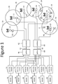
- FIG 1 is a block diagram of one embodiment of a distributed antenna system implementing a distributed receiver architecture that can be used as part of a drone racing system.
- the system of Figure 1 and the technology described herein can be used with other mobile sources (e.g., automobiles, computing devices, manned aircraft, spacecraft, etc.)
- Six drones 1, 2, 3, 4, 5 and 6 are depicted in Figure 1 . More or less than six drones can be used.
- Each drone 1, 2, 3, 4,5, 6 contains a video camera (e.g., NTSC or any other video format) which provides a first person view of the racing event.
- the NTSC signal generated by the camera is frequency modulated onto a carrier frequency and transmitted from the drone to the distributed antenna system.
- the 5.8 GHz frequency band is used as it is a popular unlicensed band worldwide.
- Each drone's carrier frequency is set to a unique channel within the 5.8 GHz frequency band to avoid interference, and the channels are allocated to provide both separation from other channels and to avoid creating in-band intermodulation distortion products.
- Intermodulation products are inevitably created regardless of frequency selection; however by using the proper frequency selection the desired signals can be allocated where we want in the spectrum to avoid on-channel collisions with intermodulation products.
- FIG. 1 shows six antennas 10, 12, 14, 16, 18 and 20. More or less than six antennas can be used. Each antenna is associated with a coverage area from within which the antenna can reliably communicate with a drone (or other mobile source). For example, antenna 10 is in and corresponds to coverage area 22, antenna 12 is in and corresponds to coverage area 24, antenna 14 is in and corresponds to coverage area 26, antenna 16 is in and corresponds to coverage area 28, antenna 18 is in and corresponds to coverage area 30, and antenna 20 is in and corresponds to coverage area 32.
- the coverage areas overlap; for example, drone 6 is depicted to be in the overlap between coverage areas 28 and 30.
- remote receiver front end module 50 is connected to antenna 10
- remote receiver front end module 52 is connected to antenna 12
- remote receiver front end module 54 is connected to antenna 14
- remote receiver front end module 56 is connected to antenna 16
- remote receiver front end module 58 is connected to antenna 18, and remote receiver front end module 60 is connected to antenna 20.
- a first combining and distribution network comprises combiner 62 and splitter 66
- a second combining and distribution network comprises combiner 64 and splitter 68.
- Combiner 62 receives and combines the signals from antenna 10 (via remote receiver front end module 50), antenna 14 (via remote receiver front end module 54), and antenna 18 (via remote receiver front end module 58) to create a first combined signal 63.
- the first combined signal 63 is provided to the input of splitter 66, which create six copies of the first combined signal and transmits each copy to a different one of the six diversity receivers 70, 72, 74, 76, 78, 80.
- Combiner 64 receives and combines the signals from antenna 12 (via remote receiver front end module 52), antenna 16 (via remote receiver front end module 56), and antenna 20 (via remote receiver front end module 60) to create a second combined signal 65.
- the second combined signal 65 is provided to the input of splitter 68, which create six copies of the second combined signal and transmits each copy to a different one of the six diversity receivers 70, 72, 74, 76, 78, 80. Therefore, each of the diversity receivers 70, 72, 74, 76, 78, 80 receives at least two signals: (1) a signal from splitter 66 and (2) a signal from splitter 68.
- each receiver potentially can receive a signal from each antenna.
- each diversity receiver 70, 72, 74, 76, 78, 80 is associated with one drone 1,2, 3, 4, 5, 6 so that each diversity receiver 70, 72, 74, 76, 78, 80 filters the received signals to identify the signals from the associated one drone.
- the diversity receivers may include band pass filters that remove signals on carriers other than the carrier used for the associated drone. So if diversity receiver 70 is associated with drone 1, then diversity receiver 70 will filter out the signals from drones 2-6 from both signals at its input. The diversity receivers are tuned to the frequency of the corresponding drone which is how they are associated. After filtering, each diversity receiver chooses one of the two filtered input signals based on signal characteristics (discussed below). The receiver then demodulates the frequency modulated carrier of the chosen signals (for the associated drone) to create an NTSC signal (or other format). In another embodiment, the diversity receiver may demodulate both signals, but discard the signal that was not chosen.
- the chosen NTSC signal is provided on the diversity receiver's output to a connected display device.
- diversity receiver 70 is connected to display 82
- diversity receiver 72 is connected to display 84
- diversity receiver 74 is connected to display 86
- diversity receiver 76 is connected to display 88
- diversity receiver 78 is connected to display 90
- diversity receiver 80 is connected to display 92.
- the displays can be head mounted displays for first person viewing, computer monitors, televisions, etc. In some cases, more than one display can receive the output of a diversity receiver. Additionally, the output of one or more diversity receivers can be broadcast via one or more television signals. In one embodiment, there is one diversity receiver and one display for each drone. In other embodiments, there can be more than one diversity receiver and/or more than one display for each drone.
- each diversity receiver receives video from each drone and outputs only one (or all or a subset) to a display. In another embodiment, each receiver only receives one video signal. In another embodiment, each receiver receives video from each drone and outputs all videos to each user.
- the system uses multiple separate signal paths so that the coverage areas 22, 24, 26, 28, 30, 32, if adjacent (and overlapping), are kept isolated and on separate signal paths to the diversity receivers.
- the antennas 10, 12, 14, 16, 18, 20 are grouped into multiple disjoint sets of multiple antennas each configured to receive signals from multiple mobile sources such as multiple drones.
- antennas 10, 14 and 18 are in a first group of multiple antennas and antennas 12, 16 and 20 are in a second group of multiple antennas.
- the coverage areas of the antennas in the first group are adjacent and overlapping with the coverage areas of the antennas in the second group.
- Adjacent antennas are in different disjoint sets of antennas.
- antenna 12 is adjacent to antennas 10 and 14, thus, antenna 12 is in a different set than antennas 10 and 14.
- the coverage area 24 for antennas 12 is adjacent and overlapping coverage areas 22 and 26 for antennas 10 and 14. This way, signals received at adjacent antennas will be kept isolated.
- the signals from the first group of multiple antennas 10,14 and 18 are transmitted to the diversity receivers 70-80 via a first signal path that includes the remote receiver front end modules, transmission line, combiner 62 and splitter 66.
- the signals from the second group of multiple antennas 12, 16 and 20 are transmitted to the diversity receivers 70-80 via a second signal path that includes remote receiver front end modules, transmission line, combiner 64 and splitter 68.
- the location of coverage areas are selected such that non-adjacent radio areas are combined into a single diversity path, thereby reducing the total number of required diversity paths.
- Each diversity receiver will receive one combined signal from each signal path. Because the system of Figure 1 includes two signal paths, each diversity receiver will receive two combined signals, one from each of the two signal paths. That is, there is one signal path for each set of antennas. In some implementations, the antennas and their associated coverage areas can be grouped into more than two disjoint sets of multiple antennas; therefore, there will be more than two signals paths. If the antennas are grouped into N disjoint sets of multiple antennas, then there will be N signals paths and each diversity receiver will receive N inputs.
- the transmission lines from the remote receiver front end modules 50, 52, 54, 56, 58, 60 to combiners 62 and 64 is coaxial cable.
- those transmission lines are fiber optic cables with RF over fiber transmit modules located at remote receiver front end modules 50, 52, 54, 56, 58, 60 and RF over fiber receive modules located at combiners 62 and 64. Replacing the coaxial cable with low loss fiber allows for a much longer cable run and thus a larger NLOS coverage area.
- a combination of coaxial cables and fiber optic cables is another possible implementation.
- Other transmission mediums can also be used.
- FIG. 2 is a block diagram of one embodiment of a diversity receiver 70, 72, 74, 76, 78 and 80, which can be implemented as one or more electrical circuits. Diversity is achieved by implementing two or more separate (i.e. not in communication) signal paths. One or more of the signal paths are chosen based on one or more signal characteristics, such as a Received Signal Strength Indicator (RSSI), link quality, clarity of video, position of an item in the video or position of the drone.
- RSSI Received Signal Strength Indicator
- Figure 2 shows N signal path input interfaces 102-1, 102-2, ... 102-N, each of which includes filters to remove the signals from all drones (or other types of sources) except one. In some embodiments, signals from more than one drone/source can be maintained.
- each diversity receiver 70, 72, 74, 76, 78, 80 filters to obtain signals from a different drone.
- signal path input interfaces 102-1, 102-2, ... 102-N includes circuits to determine RSSI or other metrics (see above) indicative of signal characteristics.
- Each of the signals output from signal path input interfaces 102-1, 102-2, ... 102-N which are signals from the same drone/source but from different signal paths, are provided to a N:1 analog switch 108, where N is the number of unique signal paths.
- the extracted signal characteristics are provided to switch logic 110 for choosing one (or more than one) signal.
- RSSI is determined for each of the signal paths to determine which path has the strongest signal.
- video output 112 is an output interface circuit for providing video to the connected display(s).
- switch 108 includes circuitry for demodulating the chosen signal to re-create the original NTSC video signal.
- the diversity receiver will demodulate all received signal paths but discard all but the chosen signal, with the choosing of signals and determining of RSSI happening after demodulation.
- the diversity receiver can have a circuit or processor between signal path input interfaces 102-1, 102-2, ... 102-N and switch 108 in order to perform the demodulation.
- the diversity receiver has a processor that controls the components depicted in Figure 2 ..
- Figure 3 is a block diagram of one embodiment of a remote receiver front end module 50, 52, 54, 56, 58, 60.
- the remote receiver front end module comprises a combination of low noise amplifier(s) 154 and 158, optional RF filters 152 and 156 and a variable attenuator 160.
- the remote receiver front end module connects to the antenna and simultaneously sets the noise figure and the total gain of the receiver. Filters are used optionally to reduce out of band noise, and the optional variable attenuator can be used to control the overall gain distribution in the case where multiple modules are used in series.
- the signal 150 from the antenna is received at filter 152 to remove noise before sending the signal to low noise amplifier 154.
- the output of low noise amplifier 154 is provided to filter 156.
- the output of filter 156 is transmitted to low noise amplifier 158 and then to attenuator 160.
- the output of attenuator 160 is transmitted toward the combiners 62 or 64.
- FIG. 4 is a block diagram of a circuit for an example inline amplifier modules to be used along the cables between the remote receiver front end module and the combiners.
- the output of an example remote receiver front end module 161 (which can be any of 50, 52, 54, 56, 58 or 60) is transmitted along cable 162 (coax or fiber optic) for approximately 100 feet (or other amount).
- cable 162 coax or fiber optic
- an inline amplifier module 164 is placed and then another 100 feet of cable, and so on.
- One example implementation of the inline amplifier module 164 includes a filter 166 with an output connected to an input of low noise amplifier 168. Filters are used optionally to reduce out of band noise.
- remote receiver front end modules and inline amplifier modules remote from the diversity receivers are what makes the system a distributed receiver system.
- a distributed receiver system By using a distributed receiver system a significant extension of range is achievable; however the challenge lies in the combining of the signal from each antenna.
- Drone racing at high speeds requires very low latency throughout the system, with some pilots wanting video feedback on the order of ⁇ 10 milliseconds in order to appropriately react to features of a race course. Therefore, one embodiment uses a NTSC analog video transmitter and an analog distributed video receiver.
- the combination of signals and redistribution to multiple end users should be achieved in such a way that the signals from multiple paths must be isolated from each other to avoid signal degradation known as multipath interference or "ghosting" as it applies to video signals.
- Identical signals from two or more signal paths in the same analog network will combine constructively if they are aligned in time, however if they are slight offset in time the can combine destructively. For example, if a drone is located at an equal distance between two or more antennas, and the signal paths are combined into a single receiver, the resulting combined signal can appear distorted and in some cases will be lost completely.
- One remediation used in the proposed system is to utilize a diversity receiver, and placing antennas in such a manner that a) there is overlap between antenna coverage areas to provide for continuity throughout the race path without loss in coverage, and b) signals from adjacent antennas are not combined into the same signal path.
- the diversity receiver can then be used to automatically switch between signal paths based on RSSI as the drone traverses from one antenna area to another. Non-adjacent antennas that are spaced sufficiently apart may be combined into a common signal path as there will never be a high enough magnitude present at each antenna simultaneously due to losses in propagation to cause significant signal degradation.
- Another challenge with combination in an analog distributed receiver is that the active elements, i.e. LNAs, mixers, demodulators, etc common in a receiver will create intermodulation distortion whenever more than one carrier (or subcarrier) frequency is present. This results in mixed frequency products that cause interference to other users.
- a common implementation of an NTSC transmitter frequency modulates video, left audio, and right audio onto separate subcarriers that are then combined before transmitting. This is further compounded when there are multiple users each transmitting multiple subcarriers, resulting in mixed frequency products that are present frequently throughout the frequency band in use.
- one method of conditioning this signal is to modify the downlink signal to remove the left and right audio subcarriers, reducing the number of 3 rd order mixed products in a system by 66%.
- a remote receiver front end module apparatus In order to remotely locate an antenna, a remote receiver front end module apparatus is used to preserve the dynamic range of the diversity receiver, in addition to amplifier modules distributed throughout the signal path.
- the arrangement and quantity may be extended without limit so long as the previous antenna placement requirement are not violated and the a) total sum of the gain of the inline amplifiers remote receiver front end module, and loss of all cables and other passive elements does not limit the cascaded noise figure of the system, and b) the third order intercept of any stage in the cascaded receiver does not exceed the 1dB compression point of any of the stages in the cascade.
- the inline amplifier apparatus has been designed such that the gain of each inline amplifier matches the loss for each incremental section of coaxial or fiber optic cable, and each diversity receiver path has been designed with cascaded NF, P1dB and IP3 characteristics such that the receiver front end module sets these key metrics of the receiver performance that all good receiver designs do.
- FIG. 5 is a flow chart describing one embodiment of a process for capturing video on the drone 1, 2, 3, 4, 5 or other mobile device. This is the video that is transmitted to the displays 82, 84, 86, 88, 90, 92 using the system of Figure 1 .
- each of the drones 1, 2, 3, 4, 5 (or other sources) captures video (standard definition or high definition).
- the captured video is used to create a NTSC signal. In other embodiments, other video formats can be used.
- the left and right audio subcarriers of the NTSC signal are removed.
- the electronics on the drone (or other mobile source) modulates the NTSC analog video signal(s) using different carrier frequencies for each drone.
- the carrier frequencies are chosen to reduce or avoid nonlinear components such as intermodulation products. For example, if the system is using two drones, then their respective carriers can be set 20MHz apart.
- An example set of frequencies for a system with six drones 1, 2, 3, 4, 5 (or other sources) are 5645 MHz, 5665 MHz, 5705 MHz, 5725 MHz, 5820 MHz, and 5840 MHz.
- a transmitter on the drones each wirelessly transmits the modulated NTSC analog video signals (without audio subcarriers) from the aircraft to one or more antennas 10, 12, 14, 16, 18, 20.
- the process of Figure 5 is performed continuously during a race or other event on multiple drones/sources.
- FIG. 6 is a flow chart describing one embodiment of a process for operating the distributed antenna system of Figure 1 in response to receiving video signals from the drones (or other sources) as per the process of Figure 5 (or a different process).
- wireless modulated analog signals are received from a first mobile source/drone (any of 1, 2, 3, 4, 5) at one or more antennas of a first set of antennas.
- Step 352 includes receiving the wireless modulated analog video signal from the first mobile source at one or more antennas of a second set of antennas.
- the second set of antennas do not include any antennas from the first set of antennas and coverage areas of the first set of antennas overlap with coverage areas of the second set of antennas, as depicted in Figure 1 .
- An example of the first set of antennas includes antennas 10, 14 and 18.
- An example of the second set of antennas includes antennas 12, 16 and 20.
- Step 354 includes transmitting the received wireless modulated analog signal from the first set of antennas to a first combining and distribution network via the first signal path.
- Step 356 includes transmitting the received wireless modulated analog signal from the second set of antennas to a second combining and distribution network via the second signal path.
- An example of the first combining and distribution network includes combiner 62, splitter 66 and remote receiver front end modules 50, 54, 58.
- An example of the second combining and distribution network includes combiner 64, splitter 68 and remote receiver front end modules 52, 56 and 60. As depicted in Figure 1 , the second signal path is separate from and not in communication with the first signal path. Steps 354 and 356 may (optionally) utilize the circuit of Figure 4 to transmit the signals.
- Step 358 includes combining output of the first set of antennas and providing the combined output of the first set of antennas to the diversity receivers as part of the first signal path.
- Step 360 includes combining output of the second set of antennas and providing the combined output of the second set of antennas to the diversity receivers as part of a second signal path.
- each diversity receiver 70, 72, 74, 76, 78, 80 chooses and outputs to displays 82, 84, 86, 88, 90, 92 one (or more than one - separate or combined) of the combined output of the first set of antennas and combined output of the second set of antennas based on a signal characteristic.
- the output video is then displayed on the connected display(s).
- the process of Figure 6 is performed continuously during a race or other event for multiple drones/sources 1, 2, 3, 4, 5.
- this proposed system sets forth a simplified version of an analog DAS system which achieves minimum latency by eliminating processing delay, allowing multiple users to coexist in a common coverage area, and is extensible to an unlimited number of remotely located antennas.
- a transmit and receive solution which employs a long range, narrowband, frequency hopping modulation scheme.
- This solution operates in the 868 and 915 MHz bands, which are unlicensed bands for the EU and Americas, respectively.
- the range of this system is extensive, however dead zones do exist depending on the environment surrounding the flight path.
- a unique implementation of this equipment is used to provide extended range into these areas.
- the signals sent to the drones are transmitted in the range of 902-928 MHz, with the ability to frequency hop among fifty channels spaced 0.5 MHz apart.
- the transmit signal from each pilot frequency "hops" every 5 milliseconds using a direct sequence to avoid interference with other users, and in this system each transmitter uses the same sequence based on the same seed to a pseudo random algorithm. Therefore, the system must be set up and provisioned so that each transmitter, while following the same frequency hopping sequence, is offset in time, thereby eliminating packet collisions.
- different drones/sources can use different seeds to avoid collisions.
- FIG. 7 is a block diagram of the components of the control system for sending flight control commands to the drones (or other sources).
- each drone 1, 2, 3, 4, 5 (not depicted in Figure 7 ) has one pilot (possibly wearing a head mounted display 82, 94, 86, 88, 90 92) and each pilot has one pilot controller 402, 404, 406, 408, 410, and 412.
- pilot controller 402, 404, 406, 408, 410, and 412 is connected to its own transmitter using a digital PPM signal.
- pilot controller 402 is connected to transmitter 420
- pilot controller 404 is connected to transmitter 422
- pilot controller 406 is connected to transmitter 424
- pilot controller 408 connected to transmitter 426
- pilot controller 410 is connected to transmitter 428
- pilot controller 412 is connected to transmitter 430.
- each transmitter is paired to a receiver on the one respective drone prior to flight, which includes exchanging keys for the beam hopping algorithm.
- the transmitters use the different hopping carrier frequencies to perform FSK modulation on the control signals from the pilot controllers.
- the output of the transmitters 420, 422, 424, 426, 428, 430 are all connected to combiner 440, which combines the six signals into one combined signal and sends that combined signal to the connected splitter 442, which makes 6 copies of the combined signal.
- the combined signal is then sent from splitter 442 to a set of antennas 450, 452, 454, 456, 458 and 460 which are placed about the race course (or other environment).
- antennas 450, 452, 454, 456, 458 and 460 are different than antennas 10, 12, 14, 16, 18, 20.
- antennas 450, 452, 454, 456, 458 and 460 are the same as antennas 10, 12, 14, 16, 18, 20.
- Antennas 450, 452, 454, 456, 458 and 460 transmit the combined signal received from splitter 442 to the drones, which filter and demodulate the signals to access the signal from its paired pilot controller and executes the flight command contained therein.
Landscapes
- Engineering & Computer Science (AREA)
- Computer Networks & Wireless Communication (AREA)
- Signal Processing (AREA)
- Mobile Radio Communication Systems (AREA)
Description
- The technology described herein relates to a wireless communications system that can be used for racing high speed radio controlled unmanned aircraft (i.e. drones) with low latency video transmission and flight control, as well as for other environments involving wireless communication with other types of mobile devices.
- Currently, existing wireless systems are limited in overall range. For example, it may be difficult to stay in communication with multiple mobile devices (such as aircraft) over a large area with obstacles that prevent line of sight.
- Existing systems are also limited in the total number of active users occupying the same coverage area. This limitation is a result of standard design practices which call for a lower Intermodulation Distortion specification for economic and power consumption purposes.
- Some existing wireless video solutions FM modulate an NTSC signal with separate carriers for video, left audio, and right audio, which result in a multicarrier FM signal being transmitted. Due to nonlinearities in the active stages of both the transmitter and receiver circuits, spurious signals are generated outside the original signal bandwidth resulting in noise being generated in adjacent channels. This noise results in a further limitation in the number of active users in a given radio range.
- Existing hardware used for the flight control communications are also limited in range due to the use of unlicensed spectrum and the rules that govern them.
US 5479397 discloses a CDMA transmission delay method and apparatus. -
-
Figure 1 is a block diagram of one embodiment of a distributed antenna system implementing a distributed receiver architecture. -
Figure 2 is a block diagram of one example of a diversity receiver. -
Figure 3 is a block diagram of one example of a remote receiver front end module. -
Figure 4 is a block diagram of one example of a remote receiver front end module apparatus combined with an inline amplifier module. -
Figure 5 is a flow chart describing one embodiment of a process for capturing video on a mobile device, such as an unmanned aircraft in a race. -
Figure 6 is a flow chart describing one embodiment of a processor for operating the distributed antenna system ofFigure 1 . -
Figure 7 is a block diagram of a system for providing control signals to mobile devices, such as an unmanned aircraft in a race. - A communication system is proposed to communicate with multiple mobile sources. For example, a distributed antenna system implementing a distributed receiver architecture can be used to receive live video from a set of unmanned aircraft. According to an aspect, there is provided a communication system as claimed in
claim 1. According to another aspect, there is provided a method for operating a communication system as claimed in claim 9. - One example implementation of the technology described herein includes a drone racing system comprising a plurality of drones, the distributed antenna system, a plurality of remote controllers that participate in unidirectional or bidirectional communication with the drones using analog communication in order to fly the drones such that each controller communicates with only one drone (or multiple drones); and a plurality of head mounted displays (or other types of displays) providing a first person view (FPV) that receive video from the drones via the distributed antenna system using analog communication such that each head mounted display receives video from one drone (or multiple drones). The controllers each include processors, memory, displays, input devices (buttons, dials, joysticks, knobs, etc), speakers, etc. and are used to remotely pilot the drones. The head mounted displays provide a virtual reality experience so that the pilot wearing the display, but remote from the drone, sees what a pilot in the drone would see via standard or high definition video. The drones can be any type of unmanned aircraft including airplanes, helicopters, other aircraft with multiple propellers (e.g., 4 propellers) or any type of drone design. In some embodiments, the drones will include one or more antennas for wireless communication with the distributed antenna system and other antennas systems to receive instructions for flight control from the remote controllers, to provide telemetry and other flight data to the remote controllers and to provide video for delivery of video from the drones to the head mounted displays.
- In one example implementation, 4-6 drones can race on a course that is indoors and/or outdoors and includes multiple types of terrain and obstacles. In many cases the pilots using the remotes controllers will not have line of sight to the drones during an entire race and will rely on the video received from the drones. The pilots use the remote controllers and the head mounted displays to fly the drones. Because the drones will fly fast and it is a race, the communication of video and commands must be low latency. If the drone is slow to respond to a flight command or a pilot is slow to react to an obstacle in the drone's path, the drone may crash.
-
Figure 1 is a block diagram of one embodiment of a distributed antenna system implementing a distributed receiver architecture that can be used as part of a drone racing system. Although the discussion below describes the system ofFigure 1 with respect to drones, the system ofFigure 1 and the technology described herein can be used with other mobile sources (e.g., automobiles, computing devices, manned aircraft, spacecraft, etc.) Sixdrones Figure 1 . More or less than six drones can be used. Eachdrone -
Figure 1 shows sixantennas antenna 10 is in and corresponds tocoverage area 22,antenna 12 is in and corresponds tocoverage area 24,antenna 14 is in and corresponds tocoverage area 26,antenna 16 is in and corresponds tocoverage area 28,antenna 18 is in and corresponds tocoverage area 30, andantenna 20 is in and corresponds tocoverage area 32. The coverage areas overlap; for example,drone 6 is depicted to be in the overlap betweencoverage areas - If a
drone coverage area antenna front end module 50 is connected toantenna 10, remote receiverfront end module 52 is connected toantenna 12, remote receiverfront end module 54 is connected toantenna 14, remote receiverfront end module 56 is connected toantenna 16, remote receiverfront end module 58 is connected toantenna 18, and remote receiverfront end module 60 is connected toantenna 20. - After being amplified by the corresponding remote receiver front end module, the amplified signal is carried across a transport medium, such as coaxial cable or fiber optic cable, to a combining and distribution network which connects the
multiple antennas multiple receivers splitter 66, and a second combining and distribution network comprises combiner 64 andsplitter 68. Combiner 62 receives and combines the signals from antenna 10 (via remote receiver front end module 50), antenna 14 (via remote receiver front end module 54), and antenna 18 (via remote receiver front end module 58) to create a first combinedsignal 63. The first combinedsignal 63 is provided to the input ofsplitter 66, which create six copies of the first combined signal and transmits each copy to a different one of the sixdiversity receivers signal 65. The second combinedsignal 65 is provided to the input ofsplitter 68, which create six copies of the second combined signal and transmits each copy to a different one of the sixdiversity receivers diversity receivers splitter 66 and (2) a signal fromsplitter 68. Thus, each receiver potentially can receive a signal from each antenna. - In one embodiment, each
diversity receiver drone diversity receiver diversity receiver 70 is associated withdrone 1, thendiversity receiver 70 will filter out the signals from drones 2-6 from both signals at its input. The diversity receivers are tuned to the frequency of the corresponding drone which is how they are associated. After filtering, each diversity receiver chooses one of the two filtered input signals based on signal characteristics (discussed below). The receiver then demodulates the frequency modulated carrier of the chosen signals (for the associated drone) to create an NTSC signal (or other format). In another embodiment, the diversity receiver may demodulate both signals, but discard the signal that was not chosen. - The chosen NTSC signal is provided on the diversity receiver's output to a connected display device. For example,
diversity receiver 70 is connected to display 82,diversity receiver 72 is connected to display 84,diversity receiver 74 is connected to display 86,diversity receiver 76 is connected to display 88,diversity receiver 78 is connected to display 90, anddiversity receiver 80 is connected to display 92. The displays can be head mounted displays for first person viewing, computer monitors, televisions, etc. In some cases, more than one display can receive the output of a diversity receiver. Additionally, the output of one or more diversity receivers can be broadcast via one or more television signals. In one embodiment, there is one diversity receiver and one display for each drone. In other embodiments, there can be more than one diversity receiver and/or more than one display for each drone. In some embodiments, some drones will not be associated with a diversity receiver and/or display. In one embodiment, each diversity receiver receives video from each drone and outputs only one (or all or a subset) to a display. In another embodiment, each receiver only receives one video signal. In another embodiment, each receiver receives video from each drone and outputs all videos to each user. - In one embodiment, the system uses multiple separate signal paths so that the
coverage areas antennas antennas antennas antenna 12 is adjacent toantennas antenna 12 is in a different set thanantennas coverage area 24 forantennas 12 is adjacent and overlappingcoverage areas antennas multiple antennas combiner 62 andsplitter 66. The signals from the second group ofmultiple antennas combiner 64 andsplitter 68. The location of coverage areas are selected such that non-adjacent radio areas are combined into a single diversity path, thereby reducing the total number of required diversity paths. - Each diversity receiver will receive one combined signal from each signal path. Because the system of
Figure 1 includes two signal paths, each diversity receiver will receive two combined signals, one from each of the two signal paths. That is, there is one signal path for each set of antennas. In some implementations, the antennas and their associated coverage areas can be grouped into more than two disjoint sets of multiple antennas; therefore, there will be more than two signals paths. If the antennas are grouped into N disjoint sets of multiple antennas, then there will be N signals paths and each diversity receiver will receive N inputs. - In one embodiment, the transmission lines from the remote receiver
front end modules combiners front end modules combiners -
Figure 2 is a block diagram of one embodiment of adiversity receiver Figure 2 shows N signal path input interfaces 102-1, 102-2, ... 102-N, each of which includes filters to remove the signals from all drones (or other types of sources) except one. In some embodiments, signals from more than one drone/source can be maintained. In one example implementation, eachdiversity receiver analog switch 108, where N is the number of unique signal paths. The extracted signal characteristics are provided to switchlogic 110 for choosing one (or more than one) signal. In the example ofFigure 2 , RSSI is determined for each of the signal paths to determine which path has the strongest signal. This process results in the strongest received signal being routed to thevideo output 112, with all other signals being isolated. In another embodiment, multiple videos can be combined into a single higher quality (or same quality) video. In one example implementation,video output 112 is an output interface circuit for providing video to the connected display(s). In one embodiment,switch 108 includes circuitry for demodulating the chosen signal to re-create the original NTSC video signal. In one embodiment, the diversity receiver will demodulate all received signal paths but discard all but the chosen signal, with the choosing of signals and determining of RSSI happening after demodulation. In another embodiment, the diversity receiver can have a circuit or processor between signal path input interfaces 102-1, 102-2, ... 102-N and switch 108 in order to perform the demodulation. In some implementation, the diversity receiver has a processor that controls the components depicted inFigure 2 .. -
Figure 3 is a block diagram of one embodiment of a remote receiverfront end module variable attenuator 160. The remote receiver front end module connects to the antenna and simultaneously sets the noise figure and the total gain of the receiver. Filters are used optionally to reduce out of band noise, and the optional variable attenuator can be used to control the overall gain distribution in the case where multiple modules are used in series. Thesignal 150 from the antenna is received atfilter 152 to remove noise before sending the signal tolow noise amplifier 154. The output oflow noise amplifier 154 is provided to filter 156. The output offilter 156 is transmitted tolow noise amplifier 158 and then toattenuator 160. The output ofattenuator 160 is transmitted toward thecombiners - In some designs, for a given length of cable between the remote receiver front end module and the combiners, whether coaxial or fiber, there is loss that should be overcome to keep the signal degradation to a minimum. One method of overcoming this loss is to use inline amplifier modules with enough gain to overcome the subsequent losses.
Figure 4 is a block diagram of a circuit for an example inline amplifier modules to be used along the cables between the remote receiver front end module and the combiners. The output of an example remote receiver front end module 161 (which can be any of 50, 52, 54, 56, 58 or 60) is transmitted along cable 162 (coax or fiber optic) for approximately 100 feet (or other amount). After approximately 100 feet (or other amount), aninline amplifier module 164 is placed and then another 100 feet of cable, and so on. In one embodiment, there will be aninline amplifier module 164 every 100 feet. One example implementation of theinline amplifier module 164 includes afilter 166 with an output connected to an input oflow noise amplifier 168. Filters are used optionally to reduce out of band noise. - The use of remote receiver front end modules and inline amplifier modules remote from the diversity receivers are what makes the system a distributed receiver system. By using a distributed receiver system a significant extension of range is achievable; however the challenge lies in the combining of the signal from each antenna. Drone racing at high speeds requires very low latency throughout the system, with some pilots wanting video feedback on the order of <10 milliseconds in order to appropriately react to features of a race course. Therefore, one embodiment uses a NTSC analog video transmitter and an analog distributed video receiver.
- For an analog DAS system without digital header information or pilot tones, the combination of signals and redistribution to multiple end users should be achieved in such a way that the signals from multiple paths must be isolated from each other to avoid signal degradation known as multipath interference or "ghosting" as it applies to video signals. Identical signals from two or more signal paths in the same analog network will combine constructively if they are aligned in time, however if they are slight offset in time the can combine destructively. For example, if a drone is located at an equal distance between two or more antennas, and the signal paths are combined into a single receiver, the resulting combined signal can appear distorted and in some cases will be lost completely. One remediation used in the proposed system is to utilize a diversity receiver, and placing antennas in such a manner that a) there is overlap between antenna coverage areas to provide for continuity throughout the race path without loss in coverage, and b) signals from adjacent antennas are not combined into the same signal path. The diversity receiver can then be used to automatically switch between signal paths based on RSSI as the drone traverses from one antenna area to another. Non-adjacent antennas that are spaced sufficiently apart may be combined into a common signal path as there will never be a high enough magnitude present at each antenna simultaneously due to losses in propagation to cause significant signal degradation.
- Another challenge with combination in an analog distributed receiver is that the active elements, i.e. LNAs, mixers, demodulators, etc common in a receiver will create intermodulation distortion whenever more than one carrier (or subcarrier) frequency is present. This results in mixed frequency products that cause interference to other users. A common implementation of an NTSC transmitter frequency modulates video, left audio, and right audio onto separate subcarriers that are then combined before transmitting. This is further compounded when there are multiple users each transmitting multiple subcarriers, resulting in mixed frequency products that are present frequently throughout the frequency band in use. As such, and as part of this proposed system, one method of conditioning this signal is to modify the downlink signal to remove the left and right audio subcarriers, reducing the number of 3rd order mixed products in a system by 66%.
- In order to remotely locate an antenna, a remote receiver front end module apparatus is used to preserve the dynamic range of the diversity receiver, in addition to amplifier modules distributed throughout the signal path. The arrangement and quantity may be extended without limit so long as the previous antenna placement requirement are not violated and the a) total sum of the gain of the inline amplifiers remote receiver front end module, and loss of all cables and other passive elements does not limit the cascaded noise figure of the system, and b) the third order intercept of any stage in the cascaded receiver does not exceed the 1dB compression point of any of the stages in the cascade. As such, the inline amplifier apparatus has been designed such that the gain of each inline amplifier matches the loss for each incremental section of coaxial or fiber optic cable, and each diversity receiver path has been designed with cascaded NF, P1dB and IP3 characteristics such that the receiver front end module sets these key metrics of the receiver performance that all good receiver designs do..
-
Figure 5 is a flow chart describing one embodiment of a process for capturing video on thedrone displays Figure 1 . Instep 302, each of thedrones step 304, the captured video is used to create a NTSC signal. In other embodiments, other video formats can be used. Instep 306, the left and right audio subcarriers of the NTSC signal are removed. Instep 308, the electronics on the drone (or other mobile source) modulates the NTSC analog video signal(s) using different carrier frequencies for each drone. The carrier frequencies are chosen to reduce or avoid nonlinear components such as intermodulation products. For example, if the system is using two drones, then their respective carriers can be set 20MHz apart. An example set of frequencies for a system with sixdrones step 310, a transmitter on the drones each wirelessly transmits the modulated NTSC analog video signals (without audio subcarriers) from the aircraft to one ormore antennas Figure 5 is performed continuously during a race or other event on multiple drones/sources. -
Figure 6 is a flow chart describing one embodiment of a process for operating the distributed antenna system ofFigure 1 in response to receiving video signals from the drones (or other sources) as per the process ofFigure 5 (or a different process). Instep 350, wireless modulated analog signals are received from a first mobile source/drone (any of 1, 2, 3, 4, 5) at one or more antennas of a first set of antennas. Step 352 includes receiving the wireless modulated analog video signal from the first mobile source at one or more antennas of a second set of antennas. The second set of antennas do not include any antennas from the first set of antennas and coverage areas of the first set of antennas overlap with coverage areas of the second set of antennas, as depicted inFigure 1 . An example of the first set of antennas includesantennas antennas - Step 354 includes transmitting the received wireless modulated analog signal from the first set of antennas to a first combining and distribution network via the first signal path. Step 356 includes transmitting the received wireless modulated analog signal from the second set of antennas to a second combining and distribution network via the second signal path. An example of the first combining and distribution network includes
combiner 62,splitter 66 and remote receiverfront end modules combiner 64,splitter 68 and remote receiverfront end modules Figure 1 , the second signal path is separate from and not in communication with the first signal path.Steps Figure 4 to transmit the signals. - Step 358 includes combining output of the first set of antennas and providing the combined output of the first set of antennas to the diversity receivers as part of the first signal path. Step 360 includes combining output of the second set of antennas and providing the combined output of the second set of antennas to the diversity receivers as part of a second signal path. In
step 362, eachdiversity receiver displays Figure 6 is performed continuously during a race or other event for multiple drones/sources - By these combinations of apparatus and methods of implementation, this proposed system sets forth a simplified version of an analog DAS system which achieves minimum latency by eliminating processing delay, allowing multiple users to coexist in a common coverage area, and is extensible to an unlimited number of remotely located antennas.
- For the flight control system, a transmit and receive solution is used which employs a long range, narrowband, frequency hopping modulation scheme. This solution operates in the 868 and 915 MHz bands, which are unlicensed bands for the EU and Americas, respectively. The range of this system is extensive, however dead zones do exist depending on the environment surrounding the flight path. A unique implementation of this equipment is used to provide extended range into these areas. By combining the uplink signal (pilot to drone) from multiple users, they can then distribute the signal from all pilots to a multitude of antennas simultaneously. Using coaxial or fiber cables, the antennas can then be located remotely and additionally placed in the areas of the dead zones. In one embodiment, the signals sent to the drones are transmitted in the range of 902-928 MHz, with the ability to frequency hop among fifty channels spaced 0.5 MHz apart. The transmit signal from each pilot frequency "hops" every 5 milliseconds using a direct sequence to avoid interference with other users, and in this system each transmitter uses the same sequence based on the same seed to a pseudo random algorithm. Therefore, the system must be set up and provisioned so that each transmitter, while following the same frequency hopping sequence, is offset in time, thereby eliminating packet collisions. In other embodiments, different drones/sources can use different seeds to avoid collisions.
-
Figure 7 is a block diagram of the components of the control system for sending flight control commands to the drones (or other sources). In one example, eachdrone Figure 7 ) has one pilot (possibly wearing a head mounteddisplay pilot controller pilot controller pilot controller 402 is connected totransmitter 420,pilot controller 404 is connected totransmitter 422,pilot controller 406 is connected totransmitter 424,pilot controller 408 connected totransmitter 426,pilot controller 410 is connected totransmitter 428 andpilot controller 412 is connected totransmitter 430. In one embodiment, each transmitter is paired to a receiver on the one respective drone prior to flight, which includes exchanging keys for the beam hopping algorithm. The transmitters use the different hopping carrier frequencies to perform FSK modulation on the control signals from the pilot controllers. The output of thetransmitters combiner 440, which combines the six signals into one combined signal and sends that combined signal to the connected splitter 442, which makes 6 copies of the combined signal. The combined signal is then sent from splitter 442 to a set ofantennas antennas antennas antennas antennas Antennas
Claims (13)
- A communication system, comprising:a plurality of antennas (10, 12, 14, 16, 18, 20) including multiple disjoint sets of multiple antennas configured to receive signals from multiple mobile sources (1, 2, 3, 4, 5, 6), the multiple disjoint sets of multiple antennas including at least a first set of antennas and a second set of antennas;wherein each antenna of the first set of antennas (10, 14, 18) is associated with a respective coverage area (22, 26, 30) from within which the antenna can reliably communicate with a first mobile source of the multiple mobile sources (1, 2, 3, 4, 5, 6), and the first set of antennas comprises antennas associated with non-adjacent coverage areas;wherein each antenna of the second set of antennas (12, 16, 20) is associated with a respective coverage area (24, 28, 32) from within which the antenna can reliably communicate with the first mobile source of the multiple mobile sources (1, 2, 3, 4, 5, 6), and the second set of antennas comprises antennas associated with non-adjacent coverage areas; andwherein coverage areas of the first set of antennas overlap with coverage areas of the second set of antennas; the communication system further comprising:multiple receivers (70, 72, 74, 76, 78, 80); andmultiple signal paths including a first signal path connected to the first set of antennas and the receivers (70, 72, 74, 76, 78, 80), and a second signal path connected to the second set of antennas and the receivers (70, 72, 74, 76, 78, 80);wherein the first signal path is configured to provide a first combined output of the first set of antennas to each of the multiple receivers (70, 72, 74, 76, 78, 80);wherein the second signal path is separate from and not in communication with the first signal path, and is configured to provide a second combined output of the second set of antennas to each of the multiple receivers (70, 72, 74, 76, 78, 80); andwherein each of the receivers (70, 72, 74, 76, 78, 80) choose to output information from the first signal path or the second signal path based on signal characteristics of the signals received from the first signal path and the second signal path.
- The system of claim 1, wherein:
adjacent antennas are in different disjoint sets of antennas. - The system of claims 1 or 2, wherein:the first signal path comprises a first combining and distribution network that combines output signals from multiple antennas of the first set of antennas to form the first combined signal and transmits the first combined signal to each of the receivers of the plurality of receivers (70, 72, 74, 76, 78, 80); andthe second signal path comprises a second combining and distribution network that combines output signals from multiple antennas of the second set of antennas to form the second combined signal and transmits the second combined signal to each of the receivers of the plurality of receivers (70, 72, 74, 76, 78, 80).
- The system of claim 1, wherein:the first signal path comprises a first set of combiners that combines output signals from multiple antennas of the first set of antennas to form the first combined signal;the first signal path comprises a splitter configured to transmit the first combined signal to each of the receivers of the plurality of receivers (70, 72, 74, 76, 78, 80);the second signal path comprises a second set of combiners that combines output signals from multiple antennas of the second set of antennas to form the second combined signal;the second signal path comprises a splitter configured to transmit the second combined signal to each of the receivers of the plurality of receivers (70, 72, 74, 76, 78, 80); andeach of the receivers (70, 72, 74, 76, 78, 80) operate on the first combined signal and the second combined signal to identify a first signal from a particular one of the mobile sources from the first combined signal and a second signal from the particular one of the mobile sources from the second combined signal and choose to output the first signal or the second signal.
- The system of any of claims 1-4, wherein:
each of the receivers (70, 72, 74, 76, 78, 80) choose to output information from the first signal path or the second signal path based on strength of the signals received from first signal path and the second signal path. - The system of any of claims 1-5, wherein:the plurality of antennas (10, 12, 14, 16, 18, 20) are configured to receive modulated analog videos signals from the multiple mobile sources (1, 2, 3, 4, 5, 6); andthe multiple mobile sources (1, 2, 3, 4, 5, 6) are unmanned aircraft that transmit on different carrier frequencies.
- The system of claim 6, wherein:
each of the receivers (70, 72, 74, 76, 78, 80) choose to output information from the first signal path or the second signal path based on video clarity of signals received from first signal path and the second signal path. - The system of any of claims 1-7, further comprising an aircraft control communication structure that comprises:controllers, wherein the multiple mobile sources (1, 2, 3, 4, 5, 6) are unmanned aircraft and each controller operates one of the aircraft;transmitters connected to the controllers;a combiner connected to the transmitter;a splitter connected to the combiner; anda set of control antennas connected to the splitter.
- A method for operating a communication system, comprising:receiving (350) a wireless modulated analog signal from a first mobile source at one or more antennas of a first set of antennas, wherein each antenna of the first set of antennas is associated with a respective coverage area from within which the antenna can reliably communicate with the first mobile source, and the first set of antennas comprises antennas associated with non-adjacent coverage areas;receiving (352) the wireless modulated analog signal from the first mobile source at one or more antennas of a second set of antennas, wherein the second set of antennas do not include any antennas from the first set of antennas, each antenna of the second set of antennas is associated with a respective coverage area from within which the antenna can reliably communicate with the first mobile source, the second set of antennas comprises antennas associated with non-adjacent coverage areas, and coverage areas of the first set of antennas overlap with coverage areas of the second set of antennas;combining (358) output of the first set of antennas and providing the combined output of the first set of antennas as part of a first signal path;combining (360) output of the second set of antennas and providing the combined output of the second set of antennas as part of a second signal path that is separate from and not in communication with the first signal path; andchoosing and outputting (362) one of the combined output of the first set of antennas and the combined output of the second set of antennas based on a signal characteristic.
- The method of claim 9, wherein:
adjacent antennas are in different sets of the first set of antennas and the second set of antennas. - The method of claims 9 or 10, further comprising:transmitting (354) the received wireless modulated analog signal from the first set of antennas to a first combining and distribution network via the first signal path, wherein the combining output of the first set of antennas and providing the combined output of the first set of antennas is performed by the first combining and distribution network; andtransmitting (356) the received wireless modulated analog signal from the second set of antennas to a second combining and distribution network via the second signal path, wherein the combining output of the second set of antennas and providing the combined output of the second set of antennas is performed by the second combining and distribution network, and the choosing and outputting is performed by a receiver that receives the provided combined output of the first set of antennas from the first combining and distribution network and the provided combined output of the second set of antennas from the second combining and distribution network.
- The method of claims 9 or 10, wherein:the receiving (350) the wireless modulated analog signal from the first mobile source at the one or more antennas of the first set of antennas is part of receiving wireless modulated analog signals from a set of mobile sources (1, 2, 3, 4, 5, 6) at the one or more antennas of a first set of antennas;the receiving (352) the wireless modulated analog signal from the first mobile source at the one or more antennas of the second set of antennas is part of receiving the wireless modulated analog signal from the set of mobile sources (1, 2, 3, 4, 5, 6) at the one or more antennas of a second set of antennas;the combined output of the first set of antennas is transmitted to a plurality of receivers (70, 72, 74, 76, 78, 80) as part of the first signal path;the combined output of the second set of antennas is transmitted to the plurality of receivers (70, 72, 74, 76, 78, 80) as part of the second signal path; andthe choosing and outputting (262) comprises each receiver (70, 72, 74, 76, 78, 80) filtering the received combined output of the first set of antennas and the received combined output of the second set of antennas to identify a first received signal from a corresponding mobile source from the first set of antennas and a second received signal from the corresponding mobile source from the second set of antennas, choosing one of the first received signal and the second received signal based on the criteria and outputting the chosen signal.
- The method of any of claims 9-12, further comprising:capturing (302) video at the first mobile source, the first mobile source is an unmanned aircraft;creating (304) a NTSC analog video signal;removing (306) audio bands of the NTSC analog video signal;modulating (308) the NTSC analog video signal; andwirelessly transmitting (310) the modulated NTSC analog video signal without audio subcarriers from the aircraft.
Applications Claiming Priority (3)
| Application Number | Priority Date | Filing Date | Title |
|---|---|---|---|
| US201562266662P | 2015-12-13 | 2015-12-13 | |
| US15/066,884 US10141996B2 (en) | 2015-12-13 | 2016-03-10 | Communication system with distributed receiver architecture |
| PCT/US2016/066310 WO2017106155A2 (en) | 2015-12-13 | 2016-12-13 | Communication system with distributed receiver architecture |
Publications (2)
| Publication Number | Publication Date |
|---|---|
| EP3387759A2 EP3387759A2 (en) | 2018-10-17 |
| EP3387759B1 true EP3387759B1 (en) | 2021-10-20 |
Family
ID=58739327
Family Applications (1)
| Application Number | Title | Priority Date | Filing Date |
|---|---|---|---|
| EP16867394.5A Active EP3387759B1 (en) | 2015-12-13 | 2016-12-13 | Communication system with distributed receiver architecture |
Country Status (5)
| Country | Link |
|---|---|
| US (1) | US10141996B2 (en) |
| EP (1) | EP3387759B1 (en) |
| CN (1) | CN108604920B (en) |
| DK (1) | DK3387759T3 (en) |
| WO (1) | WO2017106155A2 (en) |
Families Citing this family (9)
| Publication number | Priority date | Publication date | Assignee | Title |
|---|---|---|---|---|
| US9813659B1 (en) * | 2016-05-11 | 2017-11-07 | Drone Racing League, Inc. | Diversity receiver |
| US10525332B2 (en) | 2016-08-03 | 2020-01-07 | OnPoynt Unmanned Systems L.L.C. | System and method for conducting a drone race or game |
| US11165521B2 (en) * | 2016-12-13 | 2021-11-02 | Amimon Ltd. | Analog signal transmission with multiple antennas |
| DE102018218730A1 (en) * | 2018-10-31 | 2020-04-30 | Diehl Metering Gmbh | Detection of a pilot sequence on simple computers |
| EP3706326B1 (en) * | 2019-03-05 | 2024-02-21 | Hitachi Energy Ltd | Communication device for communicating between a power equipment controller and power equipment devices |
| CN110601745B (en) * | 2019-09-18 | 2021-08-20 | 无锡睿思凯科技股份有限公司 | A UAV communication method with communication/ranging dual system |
| US20230267843A1 (en) * | 2022-02-24 | 2023-08-24 | Microavia | System for repositioning UAV swarm |
| CN118494819B (en) * | 2024-07-17 | 2024-10-11 | 成都航天万欣科技有限公司 | Unmanned aerial vehicle emission controller, unmanned aerial vehicle emission system and unmanned aerial vehicle emission control method |
| US12581031B1 (en) * | 2025-05-12 | 2026-03-17 | Oleksandr Stepura | Real-time video signal relay device |
Family Cites Families (13)
| Publication number | Priority date | Publication date | Assignee | Title |
|---|---|---|---|---|
| GB2214755B (en) | 1988-01-29 | 1992-06-24 | Walmore Electronics Limited | Distributed antenna system |
| US5504936A (en) | 1991-04-02 | 1996-04-02 | Airtouch Communications Of California | Microcells for digital cellular telephone systems |
| US5240207A (en) | 1992-08-03 | 1993-08-31 | The United States Of America As Represented By The Secretary Of The Navy | Generic drone control system |
| US5724666A (en) * | 1994-03-24 | 1998-03-03 | Ericsson Inc. | Polarization diversity phased array cellular base station and associated methods |
| JP3940490B2 (en) * | 1998-03-13 | 2007-07-04 | 株式会社東芝 | Distributed antenna system |
| US7082320B2 (en) | 2001-09-04 | 2006-07-25 | Telefonaktiebolaget Lm Ericsson (Publ) | Integration of wireless LAN and cellular distributed antenna |
| US7313415B2 (en) | 2004-11-01 | 2007-12-25 | Nextg Networks, Inc. | Communications system and method |
| US8634357B2 (en) | 2007-10-30 | 2014-01-21 | Telefonaktiebolaget L M Ericsson (Publ) | Distributed antenna system |
| FR2927262B1 (en) | 2008-02-13 | 2014-11-28 | Parrot | METHOD FOR CONTROLLING A ROTARY WING DRONE |
| CN101442751B (en) * | 2008-12-29 | 2010-12-01 | 中国移动通信集团北京有限公司 | Antenna layout method, device and system |
| US20110103495A1 (en) * | 2009-11-04 | 2011-05-05 | Itt Manufacturing Enterprises, Inc. | Communications link redundancy including multiple input, multiple output architecture |
| CN102938670B (en) * | 2011-08-15 | 2015-02-11 | 航通互联网信息服务有限责任公司 | Ground-air broadband wireless communication system and method for airplane |
| US9069070B2 (en) * | 2012-06-01 | 2015-06-30 | Honeywell International Inc. | Systems and methods for the selection of antennas in aircraft navigation systems |
-
2016
- 2016-03-10 US US15/066,884 patent/US10141996B2/en active Active
- 2016-12-13 CN CN201680081718.5A patent/CN108604920B/en active Active
- 2016-12-13 WO PCT/US2016/066310 patent/WO2017106155A2/en not_active Ceased
- 2016-12-13 DK DK16867394.5T patent/DK3387759T3/en active
- 2016-12-13 EP EP16867394.5A patent/EP3387759B1/en active Active
Non-Patent Citations (1)
| Title |
|---|
| None * |
Also Published As
| Publication number | Publication date |
|---|---|
| US10141996B2 (en) | 2018-11-27 |
| US20170244457A1 (en) | 2017-08-24 |
| EP3387759A2 (en) | 2018-10-17 |
| CN108604920A (en) | 2018-09-28 |
| DK3387759T3 (en) | 2021-12-20 |
| WO2017106155A3 (en) | 2017-11-30 |
| CN108604920B (en) | 2021-08-17 |
| WO2017106155A2 (en) | 2017-06-22 |
Similar Documents
| Publication | Publication Date | Title |
|---|---|---|
| US10141996B2 (en) | Communication system with distributed receiver architecture | |
| DE202014010644U1 (en) | MULTIPLE-INPUT MULTIPLE-OUTPUT (MIMO) COMMUNICATION SYSTEM | |
| EP3183890B1 (en) | Fast terminal entry in link 16 tactical networks | |
| KR102539759B1 (en) | Transmitting apparatus and receiving apparatus using for a mobile front hole | |
| JP2004525542A5 (en) | ||
| KR101566415B1 (en) | Base transceiver interface unit and repeater having it | |
| US12451906B2 (en) | Radio frequency unit, antenna, and signal processing method | |
| WO2017196497A1 (en) | Diversity receiver | |
| CN107132854A (en) | A kind of unmanned plane, unmanned plane control method and system based on white frequency spectrum | |
| EP3082268A1 (en) | Broadband signal receiving method and device, radio-frequency processing unit and broadband antenna | |
| EP2683024A1 (en) | Antenna apparatus | |
| US5140694A (en) | Anti-intrusion defeator and locator for communication satellites | |
| CN106848606A (en) | A kind of antenna system | |
| EP2733976A1 (en) | System, device, and method for transmitting multi-input-multi-output signals | |
| US9337531B2 (en) | Method and system for antenna sharing | |
| US6639938B1 (en) | Method for dynamically routing frequency hopping signals in a multiple carrier communications system | |
| CN110224704B (en) | Radio frequency system and base station equipment | |
| EP3111583B1 (en) | Method and apparatus for high data rate communication | |
| CN104301909A (en) | Indoor distribution system MIMO single cable covering method and system | |
| EP2803146B1 (en) | Systems and methods for improved high capacity in wireless communication systems | |
| EP4068638A1 (en) | Communication apparatus and network device | |
| CN102648586B (en) | Wireless communication device | |
| EP1100212A1 (en) | Transmitting/receiving apparatus for electromagnetic signals | |
| JP4435628B2 (en) | Terrestrial digital broadcast retransmitter | |
| KR101877266B1 (en) | Remote apparatus of distributed antenna system |
Legal Events
| Date | Code | Title | Description |
|---|---|---|---|
| STAA | Information on the status of an ep patent application or granted ep patent |
Free format text: STATUS: UNKNOWN |
|
| STAA | Information on the status of an ep patent application or granted ep patent |
Free format text: STATUS: THE INTERNATIONAL PUBLICATION HAS BEEN MADE |
|
| PUAI | Public reference made under article 153(3) epc to a published international application that has entered the european phase |
Free format text: ORIGINAL CODE: 0009012 |
|
| STAA | Information on the status of an ep patent application or granted ep patent |
Free format text: STATUS: REQUEST FOR EXAMINATION WAS MADE |
|
| 17P | Request for examination filed |
Effective date: 20180703 |
|
| AK | Designated contracting states |
Kind code of ref document: A2 Designated state(s): AL AT BE BG CH CY CZ DE DK EE ES FI FR GB GR HR HU IE IS IT LI LT LU LV MC MK MT NL NO PL PT RO RS SE SI SK SM TR |
|
| AX | Request for extension of the european patent |
Extension state: BA ME |
|
| DAV | Request for validation of the european patent (deleted) | ||
| DAX | Request for extension of the european patent (deleted) | ||
| STAA | Information on the status of an ep patent application or granted ep patent |
Free format text: STATUS: EXAMINATION IS IN PROGRESS |
|
| 17Q | First examination report despatched |
Effective date: 20201022 |
|
| RAP1 | Party data changed (applicant data changed or rights of an application transferred) |
Owner name: PERFORMANCE DRONE WORKS LLC |
|
| GRAP | Despatch of communication of intention to grant a patent |
Free format text: ORIGINAL CODE: EPIDOSNIGR1 |
|
| STAA | Information on the status of an ep patent application or granted ep patent |
Free format text: STATUS: GRANT OF PATENT IS INTENDED |
|
| INTG | Intention to grant announced |
Effective date: 20210715 |
|
| GRAS | Grant fee paid |
Free format text: ORIGINAL CODE: EPIDOSNIGR3 |
|
| GRAA | (expected) grant |
Free format text: ORIGINAL CODE: 0009210 |
|
| STAA | Information on the status of an ep patent application or granted ep patent |
Free format text: STATUS: THE PATENT HAS BEEN GRANTED |
|
| AK | Designated contracting states |
Kind code of ref document: B1 Designated state(s): AL AT BE BG CH CY CZ DE DK EE ES FI FR GB GR HR HU IE IS IT LI LT LU LV MC MK MT NL NO PL PT RO RS SE SI SK SM TR |
|
| REG | Reference to a national code |
Ref country code: GB Ref legal event code: FG4D |
|
| REG | Reference to a national code |
Ref country code: CH Ref legal event code: EP |
|
| REG | Reference to a national code |
Ref country code: DE Ref legal event code: R096 Ref document number: 602016065266 Country of ref document: DE |
|
| REG | Reference to a national code |
Ref country code: IE Ref legal event code: FG4D |
|
| REG | Reference to a national code |
Ref country code: AT Ref legal event code: REF Ref document number: 1440779 Country of ref document: AT Kind code of ref document: T Effective date: 20211115 |
|
| REG | Reference to a national code |
Ref country code: DK Ref legal event code: T3 Effective date: 20211217 |
|
| REG | Reference to a national code |
Ref country code: LT Ref legal event code: MG9D |
|
| REG | Reference to a national code |
Ref country code: NL Ref legal event code: MP Effective date: 20211020 |
|
| REG | Reference to a national code |
Ref country code: AT Ref legal event code: MK05 Ref document number: 1440779 Country of ref document: AT Kind code of ref document: T Effective date: 20211020 |
|
| PG25 | Lapsed in a contracting state [announced via postgrant information from national office to epo] |
Ref country code: RS Free format text: LAPSE BECAUSE OF FAILURE TO SUBMIT A TRANSLATION OF THE DESCRIPTION OR TO PAY THE FEE WITHIN THE PRESCRIBED TIME-LIMIT Effective date: 20211020 Ref country code: LT Free format text: LAPSE BECAUSE OF FAILURE TO SUBMIT A TRANSLATION OF THE DESCRIPTION OR TO PAY THE FEE WITHIN THE PRESCRIBED TIME-LIMIT Effective date: 20211020 Ref country code: FI Free format text: LAPSE BECAUSE OF FAILURE TO SUBMIT A TRANSLATION OF THE DESCRIPTION OR TO PAY THE FEE WITHIN THE PRESCRIBED TIME-LIMIT Effective date: 20211020 Ref country code: BG Free format text: LAPSE BECAUSE OF FAILURE TO SUBMIT A TRANSLATION OF THE DESCRIPTION OR TO PAY THE FEE WITHIN THE PRESCRIBED TIME-LIMIT Effective date: 20220120 Ref country code: AT Free format text: LAPSE BECAUSE OF FAILURE TO SUBMIT A TRANSLATION OF THE DESCRIPTION OR TO PAY THE FEE WITHIN THE PRESCRIBED TIME-LIMIT Effective date: 20211020 |
|
| PG25 | Lapsed in a contracting state [announced via postgrant information from national office to epo] |
Ref country code: IS Free format text: LAPSE BECAUSE OF FAILURE TO SUBMIT A TRANSLATION OF THE DESCRIPTION OR TO PAY THE FEE WITHIN THE PRESCRIBED TIME-LIMIT Effective date: 20220220 Ref country code: SE Free format text: LAPSE BECAUSE OF FAILURE TO SUBMIT A TRANSLATION OF THE DESCRIPTION OR TO PAY THE FEE WITHIN THE PRESCRIBED TIME-LIMIT Effective date: 20211020 Ref country code: PT Free format text: LAPSE BECAUSE OF FAILURE TO SUBMIT A TRANSLATION OF THE DESCRIPTION OR TO PAY THE FEE WITHIN THE PRESCRIBED TIME-LIMIT Effective date: 20220221 Ref country code: PL Free format text: LAPSE BECAUSE OF FAILURE TO SUBMIT A TRANSLATION OF THE DESCRIPTION OR TO PAY THE FEE WITHIN THE PRESCRIBED TIME-LIMIT Effective date: 20211020 Ref country code: NO Free format text: LAPSE BECAUSE OF FAILURE TO SUBMIT A TRANSLATION OF THE DESCRIPTION OR TO PAY THE FEE WITHIN THE PRESCRIBED TIME-LIMIT Effective date: 20220120 Ref country code: NL Free format text: LAPSE BECAUSE OF FAILURE TO SUBMIT A TRANSLATION OF THE DESCRIPTION OR TO PAY THE FEE WITHIN THE PRESCRIBED TIME-LIMIT Effective date: 20211020 Ref country code: LV Free format text: LAPSE BECAUSE OF FAILURE TO SUBMIT A TRANSLATION OF THE DESCRIPTION OR TO PAY THE FEE WITHIN THE PRESCRIBED TIME-LIMIT Effective date: 20211020 Ref country code: HR Free format text: LAPSE BECAUSE OF FAILURE TO SUBMIT A TRANSLATION OF THE DESCRIPTION OR TO PAY THE FEE WITHIN THE PRESCRIBED TIME-LIMIT Effective date: 20211020 Ref country code: GR Free format text: LAPSE BECAUSE OF FAILURE TO SUBMIT A TRANSLATION OF THE DESCRIPTION OR TO PAY THE FEE WITHIN THE PRESCRIBED TIME-LIMIT Effective date: 20220121 Ref country code: ES Free format text: LAPSE BECAUSE OF FAILURE TO SUBMIT A TRANSLATION OF THE DESCRIPTION OR TO PAY THE FEE WITHIN THE PRESCRIBED TIME-LIMIT Effective date: 20211020 |
|
| REG | Reference to a national code |
Ref country code: DE Ref legal event code: R097 Ref document number: 602016065266 Country of ref document: DE |
|
| PG25 | Lapsed in a contracting state [announced via postgrant information from national office to epo] |
Ref country code: SM Free format text: LAPSE BECAUSE OF FAILURE TO SUBMIT A TRANSLATION OF THE DESCRIPTION OR TO PAY THE FEE WITHIN THE PRESCRIBED TIME-LIMIT Effective date: 20211020 Ref country code: SK Free format text: LAPSE BECAUSE OF FAILURE TO SUBMIT A TRANSLATION OF THE DESCRIPTION OR TO PAY THE FEE WITHIN THE PRESCRIBED TIME-LIMIT Effective date: 20211020 Ref country code: RO Free format text: LAPSE BECAUSE OF FAILURE TO SUBMIT A TRANSLATION OF THE DESCRIPTION OR TO PAY THE FEE WITHIN THE PRESCRIBED TIME-LIMIT Effective date: 20211020 Ref country code: MC Free format text: LAPSE BECAUSE OF FAILURE TO SUBMIT A TRANSLATION OF THE DESCRIPTION OR TO PAY THE FEE WITHIN THE PRESCRIBED TIME-LIMIT Effective date: 20211020 Ref country code: EE Free format text: LAPSE BECAUSE OF FAILURE TO SUBMIT A TRANSLATION OF THE DESCRIPTION OR TO PAY THE FEE WITHIN THE PRESCRIBED TIME-LIMIT Effective date: 20211020 Ref country code: CZ Free format text: LAPSE BECAUSE OF FAILURE TO SUBMIT A TRANSLATION OF THE DESCRIPTION OR TO PAY THE FEE WITHIN THE PRESCRIBED TIME-LIMIT Effective date: 20211020 |
|
| REG | Reference to a national code |
Ref country code: CH Ref legal event code: PL |
|
| PLBE | No opposition filed within time limit |
Free format text: ORIGINAL CODE: 0009261 |
|
| STAA | Information on the status of an ep patent application or granted ep patent |
Free format text: STATUS: NO OPPOSITION FILED WITHIN TIME LIMIT |
|
| REG | Reference to a national code |
Ref country code: BE Ref legal event code: MM Effective date: 20211231 |
|
| 26N | No opposition filed |
Effective date: 20220721 |
|
| PG25 | Lapsed in a contracting state [announced via postgrant information from national office to epo] |
Ref country code: LU Free format text: LAPSE BECAUSE OF NON-PAYMENT OF DUE FEES Effective date: 20211213 Ref country code: IE Free format text: LAPSE BECAUSE OF NON-PAYMENT OF DUE FEES Effective date: 20211213 Ref country code: AL Free format text: LAPSE BECAUSE OF FAILURE TO SUBMIT A TRANSLATION OF THE DESCRIPTION OR TO PAY THE FEE WITHIN THE PRESCRIBED TIME-LIMIT Effective date: 20211020 |
|
| PG25 | Lapsed in a contracting state [announced via postgrant information from national office to epo] |
Ref country code: SI Free format text: LAPSE BECAUSE OF FAILURE TO SUBMIT A TRANSLATION OF THE DESCRIPTION OR TO PAY THE FEE WITHIN THE PRESCRIBED TIME-LIMIT Effective date: 20211020 Ref country code: BE Free format text: LAPSE BECAUSE OF NON-PAYMENT OF DUE FEES Effective date: 20211231 |
|
| PG25 | Lapsed in a contracting state [announced via postgrant information from national office to epo] |
Ref country code: LI Free format text: LAPSE BECAUSE OF NON-PAYMENT OF DUE FEES Effective date: 20211231 Ref country code: CH Free format text: LAPSE BECAUSE OF NON-PAYMENT OF DUE FEES Effective date: 20211231 |
|
| PG25 | Lapsed in a contracting state [announced via postgrant information from national office to epo] |
Ref country code: HU Free format text: LAPSE BECAUSE OF FAILURE TO SUBMIT A TRANSLATION OF THE DESCRIPTION OR TO PAY THE FEE WITHIN THE PRESCRIBED TIME-LIMIT; INVALID AB INITIO Effective date: 20161213 |
|
| P01 | Opt-out of the competence of the unified patent court (upc) registered |
Effective date: 20230518 |
|
| PG25 | Lapsed in a contracting state [announced via postgrant information from national office to epo] |
Ref country code: CY Free format text: LAPSE BECAUSE OF FAILURE TO SUBMIT A TRANSLATION OF THE DESCRIPTION OR TO PAY THE FEE WITHIN THE PRESCRIBED TIME-LIMIT Effective date: 20211020 |
|
| PG25 | Lapsed in a contracting state [announced via postgrant information from national office to epo] |
Ref country code: MK Free format text: LAPSE BECAUSE OF FAILURE TO SUBMIT A TRANSLATION OF THE DESCRIPTION OR TO PAY THE FEE WITHIN THE PRESCRIBED TIME-LIMIT Effective date: 20211020 |
|
| PG25 | Lapsed in a contracting state [announced via postgrant information from national office to epo] |
Ref country code: MT Free format text: LAPSE BECAUSE OF FAILURE TO SUBMIT A TRANSLATION OF THE DESCRIPTION OR TO PAY THE FEE WITHIN THE PRESCRIBED TIME-LIMIT Effective date: 20211020 |
|
| PG25 | Lapsed in a contracting state [announced via postgrant information from national office to epo] |
Ref country code: TR Free format text: LAPSE BECAUSE OF FAILURE TO SUBMIT A TRANSLATION OF THE DESCRIPTION OR TO PAY THE FEE WITHIN THE PRESCRIBED TIME-LIMIT Effective date: 20211020 |
|
| PGFP | Annual fee paid to national office [announced via postgrant information from national office to epo] |
Ref country code: DE Payment date: 20251119 Year of fee payment: 10 |
|
| PGFP | Annual fee paid to national office [announced via postgrant information from national office to epo] |
Ref country code: GB Payment date: 20251119 Year of fee payment: 10 |
|
| PGFP | Annual fee paid to national office [announced via postgrant information from national office to epo] |
Ref country code: DK Payment date: 20251119 Year of fee payment: 10 Ref country code: IT Payment date: 20251119 Year of fee payment: 10 |
|
| PGFP | Annual fee paid to national office [announced via postgrant information from national office to epo] |
Ref country code: FR Payment date: 20251119 Year of fee payment: 10 |