EP3387620B1 - Method for aligning at least one part of one digital image to at least one part of another digital image - Google Patents
Method for aligning at least one part of one digital image to at least one part of another digital image Download PDFInfo
- Publication number
- EP3387620B1 EP3387620B1 EP16822920.1A EP16822920A EP3387620B1 EP 3387620 B1 EP3387620 B1 EP 3387620B1 EP 16822920 A EP16822920 A EP 16822920A EP 3387620 B1 EP3387620 B1 EP 3387620B1
- Authority
- EP
- European Patent Office
- Prior art keywords
- digital image
- correlation
- tile
- tiles
- fov
- Prior art date
- Legal status (The legal status is an assumption and is not a legal conclusion. Google has not performed a legal analysis and makes no representation as to the accuracy of the status listed.)
- Active
Links
Images


Classifications
-
- G—PHYSICS
- G06—COMPUTING OR CALCULATING; COUNTING
- G06T—IMAGE DATA PROCESSING OR GENERATION, IN GENERAL
- G06T7/00—Image analysis
- G06T7/30—Determination of transform parameters for the alignment of images, i.e. image registration
- G06T7/32—Determination of transform parameters for the alignment of images, i.e. image registration using correlation-based methods
-
- G—PHYSICS
- G06—COMPUTING OR CALCULATING; COUNTING
- G06T—IMAGE DATA PROCESSING OR GENERATION, IN GENERAL
- G06T3/00—Geometric image transformations in the plane of the image
- G06T3/20—Linear translation of whole images or parts thereof, e.g. panning
-
- G—PHYSICS
- G06—COMPUTING OR CALCULATING; COUNTING
- G06T—IMAGE DATA PROCESSING OR GENERATION, IN GENERAL
- G06T2207/00—Indexing scheme for image analysis or image enhancement
- G06T2207/10—Image acquisition modality
- G06T2207/10056—Microscopic image
-
- G—PHYSICS
- G06—COMPUTING OR CALCULATING; COUNTING
- G06T—IMAGE DATA PROCESSING OR GENERATION, IN GENERAL
- G06T2207/00—Indexing scheme for image analysis or image enhancement
- G06T2207/10—Image acquisition modality
- G06T2207/10064—Fluorescence image
-
- G—PHYSICS
- G06—COMPUTING OR CALCULATING; COUNTING
- G06T—IMAGE DATA PROCESSING OR GENERATION, IN GENERAL
- G06T2207/00—Indexing scheme for image analysis or image enhancement
- G06T2207/20—Special algorithmic details
- G06T2207/20016—Hierarchical, coarse-to-fine, multiscale or multiresolution image processing; Pyramid transform
-
- G—PHYSICS
- G06—COMPUTING OR CALCULATING; COUNTING
- G06T—IMAGE DATA PROCESSING OR GENERATION, IN GENERAL
- G06T2207/00—Indexing scheme for image analysis or image enhancement
- G06T2207/20—Special algorithmic details
- G06T2207/20021—Dividing image into blocks, subimages or windows
-
- G—PHYSICS
- G06—COMPUTING OR CALCULATING; COUNTING
- G06T—IMAGE DATA PROCESSING OR GENERATION, IN GENERAL
- G06T2207/00—Indexing scheme for image analysis or image enhancement
- G06T2207/30—Subject of image; Context of image processing
- G06T2207/30004—Biomedical image processing
-
- G—PHYSICS
- G06—COMPUTING OR CALCULATING; COUNTING
- G06T—IMAGE DATA PROCESSING OR GENERATION, IN GENERAL
- G06T2207/00—Indexing scheme for image analysis or image enhancement
- G06T2207/30—Subject of image; Context of image processing
- G06T2207/30004—Biomedical image processing
- G06T2207/30024—Cell structures in vitro; Tissue sections in vitro
Definitions
- the present invention relates to a method and a system for aligning at least one part of one digital image to another digital image.
- the present invention particularly relates to a method and a system for aligning at least one part of one digital image to another digital image in a sequencing apparatus for analyzing biomolecules by detecting fluorescence signals from a sample probe.
- Biotechnology, medicine and related technical fields are based on the analysis of molecules.
- Electronic devices can analyse molecules with high precision and specificity.
- automated electronic devices have been developed for analysing large numbers of samples by routine methods.
- DNA sequencing apparatus are used for routine analysis of large numbers of DNA probes.
- Protein samples can be analysed by high throughput screening and related methods.
- electronic devices detect fluorescent signals emitted from the sample probes. This is possible when molecules, such as nucleic acids or proteins, have been labelled with fluorescent compounds such as dyes.
- NGS next-generation sequencing
- NGS NGS
- sequencing is performed by repeated cycles of polymerase-mediated nucleotide extensions or, in one format, by iterative cycles of oligonucleotide ligation.
- NGS generates hundreds of megabases to gigabases of nucleotide-sequence output in a single instrument run, depending on the platform.
- the inexpensive production of large volumes of sequence data is the primary advantage over conventional methods.
- NGS platforms and common applications/fields for NGS technologies are e.g. reviewed in Voelkerding et al, Clinical Chemistry 55:4 641-658, 2009 and Metzker, Nature Reviews/ Genetics Volume 11, January 2010, pages 31-46 .
- oligonucleotides of interest are covalently attached to a support.
- a nucleotide labelled with a fluorescent dye is attached to the growing oligonucleotide chain with DNA polymerase.
- fluorescent signals emitted from a probe can be detected and the type of nucleotide attached to the oligonucleotide can be identified.
- the fluorescent dye is cleaved off and the next synthesis cycle is carried out, in which a new labelled nucleotide is attached to the growing chain.
- the sequence of a growing oligonucleotide chain can be determined in a stepwise manner. The working steps are carried out in an automated sequencing apparatus.
- US 2010/0323350 A1 and WO 2009/117119 A1 relate to methods and compositions for determining the identity of nucleic acids in nucleotide sequences using, for example, data obtained from sequencing by synthesis methods.
- WO 2008/097455 A1 relates to an imaging system for exciting and measuring fluorescence on or in samples comprising fluorescent materials, e.g. fluorescent labels, dyes or pigments, in particular to detect fluorescent labels on nucleic acid. Moreover, a device is disclosed being configured such that fluorescent labels in a plurality of different DNA templates are simultaneously detected.
- fluorescent materials e.g. fluorescent labels, dyes or pigments
- WO 2014/020137 A1 relates to a method for enriching target sequences from a sequencing library to provide a target enriched sequencing library, wherein the sequencing library is suitable for massive parallel sequencing and comprises a plurality of double-stranded nucleic - acid molecules.
- US 6,738,532 B1 relates to image registration using a two stage registration process.
- Fluorescent signals emitted from sample probes with labelled molecules are weak, but the signals have to be detected with high precision and specificity. Thus, precise optical equipment, especially cameras and scanning technology, is required for such processes.
- the method according to the present invention is computer-implemented. However, it is understood by the skilled person that there are also other ways of implementing the method according to the present invention.
- the digital images for analyzing biomolecules in a sequencing apparatus are captured/obtained in a sequential order. Between the capturing steps, the field of view or the image section can change, e.g. caused by the movement of the flow-cell of the sequencing apparatus, which leads to misaligned digital images.
- the goal of the image registration is to remove the misalignments of the digital images.
- the process also has to be capable to compensate lens distortions to support the subsequent processing steps of the sequencing pipeline.
- One of the advantages of using a computer-implemented method rather than a static hardware or calibration solution is to ensure a high reliability of the system over a long time-period, e.g. by inherently compensate nascent backlash of the mechanical components. For example, ageing of the sequencing apparatus has to be compensated. Moreover, by avoiding the calibration and re-calibration, which would otherwise be necessary, the maintenance costs are reduced in general.
- the invention relates to a method for aligning at least one part of a second digital image with at least one part of a first digital image.
- the method further comprises the step of determining the position of a global maximum correlation value p_v' for each of the plurality of correlation images fci_v'.
- the method also comprises aligning the at least one part of the second digital image with the at least one part of the first digital image by applying the corresponding first offset vectors fov.
- step of aligning further comprises transforming the tile t_siv" or the position of at least one object in the tile t_siv" by applying the corresponding first offset vector fov_ ⁇ ".
- the plurality of tiles t_fi and t_si are distributed over the first and second digital image respectively to cover only a part of the first and second digital image.
- the plurality of tiles t_fi and t_si may be equally sized and distributed on a regular grid having a cell size larger than the size of the tiles.
- the method may further comprise after calculating the offset vectors fov, assigning the offset vector fov_ ⁇ " to a predetermined region of the tile t_siv".
- the predetermined region may be the center of the tile t_siv".
- the method may further comprise after calculating the offset vectors fov, a regression analysis step to determine the parameters of a predetermined function based on the assigned offset vector fov_ ⁇ " and wherein the step of aligning may further comprise transforming the second digital image by applying said function.
- the predetermined function may for example be a degree three polynomial function.
- the plurality of tiles t_fi and t_si are preferably distributed on the first and second digital image, respectively, to not overlap.
- an adequate tiling can be constructed by placing equally sized tiles on a regular grid with a cell size exceeding the size of the tiles.
- the offset vectors are calculated for every tile through computation of a correlation image and substraction of the subpixel-precise position of the maximal correlation value from the center position.
- the computation cost is dominated by the calculation of the correlation images, and limitation to a small fraction of the image area is able to reduce the computational cost involved.
- every offset vector may be assigned to the center position of the corresponding tile.
- S ⁇ (x1, y1, dx1, dy1), (x2, y2, dx2, dy2),..., (xn, yn, dxn, dyn) ⁇ where xi and yi are the coordinates of the i-th center position and dxi and dyi are the corresponding offsets in the direction of the coordinate axis.
- a degree 3 polynomial is adequate in the context of automated fluorescence microscopy imaging.
- Polynomials have the additional benefit that they are linear functions in their coefficients, so efficient methods for linear last squares regression can be applied for the identification of optimal parameters.
- mapping g(x,y) (x,y) + f(x,y).
- a minimal footprint for storing the resulting mapping may be achieved.
- the full mapping it is sufficient to store 8 parameters which, in IEEE-754 single precision floating point format, amounts to 32 byte of memory.
- method according the present invention comprises the step of transforming the position of at least one object in the tile t_siv" by applying the corresponding first offset vector fov_ ⁇ " after the step of calculating a plurality of first offset vectors fov.
- One of the advantages of only transforming the position of the at least one object in the tile t_siv” is that not all pixels of the respective tile t_siv" have to be transformed, which is less time-consuming and less resources-consuming.
- the term "object” relates to a predetermined region within the digital image.
- the predetermined region may be determined by evaluating the intensity at specific regions of the digital image.
- the at least one object is a bead preferably being configured to receive DNA and/or RNA.
- the method according to the present invention further comprises the following steps:
- the method according to the present invention further comprises the step of transforming the at least one part of the second digital image by applying the calculated offset vector sov.
- the method according to the present invention further comprises the step of transforming the second digital image by applying the calculated offset vector sov.
- these steps are performed before performing the step of dividing the at least one part of the second digital image into the plurality of tiles t_si.
- transforming comprises an affine transformation, i.e. a translation.
- the transformation relates to a complete shift of the whole image, in particular an integer pixel shift of the whole image.
- the transformation is generally defined by mapping every pixel in t_siv" to the reference coordinate system (defined by t_fiv”). That is, a new image t_riv” is generated, wherein “r” stands for registered, in which the intensity of every pixel (x, y) corresponds to the intensity at the corresponding pixel (x, y)+fov_v" in t_siv".
- predetermined regions regions of interest
- x, y regions of interest
- fov_v regions of interest
- integer pixels are mapped to integer pixels by said transformation. It should be clear to the skilled person that non-integer pixel positions may be handled using interpolation.
- the present invention is generally concerned with small shifts between the first and the second digital image.
- possible "artefacts” due to the appearance of holes and overlaps created by the transformation are less significant and may be tolerated.
- These artefacts are even less significant if only predetermined regions of the image are transformed.
- the step of transforming the at least one part of the second digital image is performed only if the offset between the at least one part of the second digital image and the at least one part of the first digital image is exceeding a predetermined limit.
- the limit comprises the length of the offset vector sov.
- the limit comprises at least one of the vector components.
- the step of transforming the at least one part of the second digital image is performed only if at least one of the vector components is larger than a predetermined value, more preferably if at least one of the vector components is larger than 10 pixels and/or 10% of a lateral size of a respective tile t_siv or the tile size of a respective tile t_t_siv.
- the predetermined limit is determined under consideration of the size of the at least one part of the second digital image and the first digital image.
- each tile t_fiv of the plurality of tiles t_fi has the length l_1 in the first direction and the length l_2 in the second direction.
- the first and/or the second digital image contains at least one object carrying a fluorescent compound and wherein the first digital image and/or the second digital image is obtained by an optical imaging system during emission of electromagnetic radiation by the fluorescent compound.
- the first digital image and/or the second digital image is obtained by an optical imaging system during reflective illumination, preferably during reflective white-light illumination.
- the correlation between the tile t_siv' and the corresponding tile t_fiv' is computed by phase-correlation or cross-correlation of the tile t_siv' and the corresponding tile t_fiv'.
- the correlation between the at least one part of the first digital image and the at least one part of the second digital image is computed by phase-correlation or cross-correlation of the at least one part of the first digital image and the at least one part of the second digital image.
- the present invention also refers to a system for aligning at least one part of a second digital image with at least one part of a first digital image.
- the system is configured to carry out the steps of any of the methods according to any of the preceding claims.
- the system further comprises a fourth unit configured to determine the position of a global maximum correlation value p_v' for each of the plurality of correlation images fci_ ⁇ '.
- the system further comprises a transformation unit configured to transform the tile t_siv" by applying the corresponding first offset vector fov_v" after the step of calculating a plurality of first offset vectors fov.
- a transformation unit configured to transform the tile t_siv" by applying the corresponding first offset vector fov_v" after the step of calculating a plurality of first offset vectors fov.
- the system further comprises a transformation unit configured to transform the position of at least one object in the tile t_siv" by applying the corresponding first offset vector fov_v" after the step of calculating a plurality of first offset vectors fov.
- a transformation unit configured to transform the position of at least one object in the tile t_siv" by applying the corresponding first offset vector fov_v" after the step of calculating a plurality of first offset vectors fov.
- the system further comprises a unit configured to create a correlation image sci by computing the correlation between the at least one part of the first digital image and the at least one part of the second digital image.
- the system further comprises a unit configured to determine the position of a global maximum correlation value of the correlation image sci.
- the system further comprises a unit configured to calculate an offset vector sov between the at least one part of the first digital image and the at least one part of the second digital image by considering the center position of the first correlation image and the position of the global maximum correlation value of the first correlation image.
- the system further comprises unit configured to transform the at least one part of the second digital image and/or the second digital image by applying the calculated offset vector sov.
- these steps are performed before performing the step of dividing the at least one part of the second digital image into the plurality of tiles t_si.
- the present invention also relates to a computer program product comprising one or more computer readable media having computer executable instructions for performing the steps of any of the aforementioned methods.
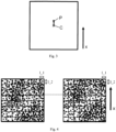
- Fig. 1 shows an exemplary sketch of a first digital image representing a so-called white-light image, i.e. a digital image being obtained using an optical imaging system during reflective white-light illumination of a part of the flow cell of the sequencing apparatus.
- An exemplary white-light image is shown in Fig. 2a .
- the exemplary white-light image is color-inverted for illustrative purposes.
- Fig. 1 shows an exemplary sketch of a second digital image representing a so-called fluorescence image, i.e. an image being obtained during emission of fluorescent compounds, wherein a fluorescent compound is attached to a bead being configured to receive on the surface at least one molecule comprising DNA or RNA.
- fluorescence image i.e. an image being obtained during emission of fluorescent compounds, wherein a fluorescent compound is attached to a bead being configured to receive on the surface at least one molecule comprising DNA or RNA.
- beads are for example commercially available, e.g., from Thermo Fisher Scientific Inc., e.g. under the brand Dynabeads, see reference [1].
- exemplary fluorescence image is shown in Fig. 2b .
- the exemplary fluorescence image is color-inverted for illustrative purposes.
- Fig. 1 the beads are shown as black dots. However, it is understood by the skilled person that the size of the beads and the number of the beads are chosen for illustrative purposes and do not reflect their actual size and number.
- Fig. 3 shows an exemplary sketch of a correlation image between the sketch of the first digital image as shown in Fig. 1 and the sketch of the second digital image as shown in Fig. 1 .
- the correlation image is preferably correlated by cross-correlation.
- there is a peak P in the correlation image i.e. a global maximum correlation value in the correlation image, displaced from the center C in the "x"-direction. This displacement of the peak P in the correlation image from the center directly results from the offset between the sketch representing the first digital image and the sketch representing the second digital image.
- Fig. 4 shows an exemplary division of the sketch of the second digital image as shown in Fig. 1 and the sketch of the second digital image as shown in Fig. 1 into a plurality of tiles according to a preferred embodiment of the present invention.
- the first digital image is divided into 64 tiles t_fi and the second digital image is divided into 64 tiles t_si.
- Each tile t_fiv of the 64 tiles t_fi of the first digital image and each tile t_siv of the 64 tiles t_si of the second digital image have a length l_1 in a direction perpendicular to the "x"-direction as shown in fig. 4 and a length l_2 in the "x"-direction, wherein both lengths l_1 and l_2 are the same.
- the tiles t_fiv and the tiles t_siv have the same size.
- a correlation image fci_ ⁇ for each tile t_fiv and each tile t_siv is created resulting in 64 correlation images fci.
- the correlation images fci are computed in this embodiment by cross-correlation.
- the position of a respective peak, i.e. a respective global maximum correlation value, in each of the plurality of correlation images fci_v is determined.
- an offset vector fov_v between the tile t_fiv and the corresponding tile t_siv for each of the 64 pairs of tiles is calculated.
- the calculations are performed considering the center position of the respective correlation image fci_v and the position of the global maximum correlation value p_v of the correlation images fci_v.
- a bead position is transformed using the respective offset vector fov_ ⁇ , wherein the bead is located in the tile t_siv.
- the bead is located in the tile t_siv.
- the bead position is transformed and not the whole tile t_siv.
- One of the advantages of only transforming the bead position then rather the whole tile is that not all pixels of the respective tile have to be transformed, and in particular not the whole second digital image, which is less time-consuming and requires less resources.
- not only one bead position can be transformed in the respective tile t_siv but also a plurality of bead positions can be transformed in the respective tile t_siv without having to transform all pixels of the respective tile.
- at least one bead position can be transformed in every tile t_siv or merely at least one bead position in some of the tiles t_si without having to transform all pixels.
- Fig. 5 shows an example, where the offset between the first digital image and the second digital image is larger than a predetermined value, according to this preferred embodiment larger than the block size of the subdivision, i.e. larger than a fraction of the length l_1 and/or l_2 of the tiles t_fiv and t_siv.
- the tiles would not overlap and the registration process would fail. Therefore, a global registration is performed before the aforementioned explained method of alignment using the division into tiles.
- One of the advantages of such a global registration is the improvement of robustness of the alignment method.
- the offset between the first digital image in the second digital image in "x"-direction is larger than the size l_2 of the tiles t_fiv and t_siv if one would directly divide the first digital image and the second digital image into a plurality of tiles t_fi/ t_si. As a consequence, there would be no overlap between tile t_fiv and tile t_siv and the registration would fail.
- a correlation image sci between the first digital image and the second digital image is created by computing the correlation between the first digital image and the second digital image.
- the correlation image is created by cross-correlation.
- the position of the global maximum correlation value of the correlation image sci i.e. the peak value of the correlation image as shown for example in Fig. 3 is determined.
- an offset vector sov between the first digital image and the second digital image is calculated by considering the center position of the first correlation image and the position of the global maximum correlation value of the first correlation image.
- the second digital image is transformed by applying the calculated offset vector sov.
- the aforementioned translation is performed by an affine transformation.
- the limit comprises at least one of the vector components.
- the second digital image is transformed by applying the calculated offset vector sov only if at least one of the vector components is larger than a predetermined value, e.g. 10% of a lateral size of a respective tile t_siv or 10% of a lateral size of a respective tile t_siv.
- One of the advantages of only transforming the second digital image, if the offset between the first digital image and the second digital image is exceeding a predetermined limit, is that a time-consuming and resource-consuming global transformation has only to be performed if the offset is too high, thus, resulting in failed registration process.
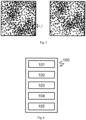
- Fig. 6 shows an exemplary system 100 according to a preferred embodiment of the present invention.
- system 100 is configured to carry out the method steps as presented in the embodiment with reference to Fig. 4 .
- the system 100 comprises a first unit 101 which divides the first digital image into a plurality of tiles t_fi. After the first unit 101 has divided the first digital image into a plurality of tiles t_fi, a second unit 102 divides the second digital image into a plurality of tiles t_si. It is understood by the skilled person, that both processes can be performed by the first unit 101 and the second unit 102 simultaneously. As an alternative, is also understood by the skilled person that the second unit 102 can divide the second digital image into a plurality of tiles t_si before the first unit 101 divides the first digital image into a plurality of tiles t_fi. The result of a division performed by the first unit 101 is presented on the left side of Fig. 4 . The result of the division performed by the second unit 102 is presented on the right side of Fig. 4 .
- the system 100 further comprises a third unit 103 which creates a plurality of correlation images fci by computing the correlation between each tile t_siv and the corresponding tile t_fiv.
- system 100 further comprises a fourth unit 104 which determines the peak position p_ v of the correlation image for each correlation image fci_v, i.e. the position of a global maximum correlation value for each correlation image fci_v.
- the system 100 further comprises a fifth unit 105 which calculates for each pair t_fiv and t_siv the offset vector fov_ ⁇ by considering the center position of the corresponding correlation image fci_ ⁇ and the peak position p_ ⁇ .
- the fifth unit 105 is configured to calculate fov_v by using the formula as presented in the embodiment with reference to Fig. 4 .
- Fig. 7 shows an exemplary system 100 according to another preferred embodiment of the present invention.
- the system 100 comprises the same units as the system 100 according to the preferred embodiment with reference to Fig. 6 .
- the system 100 further comprises a unit 101-1 which creates a correlation image sci by computing the correlation between the first digital image and the second digital image.
- a unit 101-2 determines the position of a global maximum correlation value of the correlation image sci.
- the unit 101-3 calculates an offset vector sov between the first digital image and the second digital image by considering the center position sci of the first correlation image and the position of the global maximum correlation value of the first correlation image sci.
- the unit 101-4 is transforming the second digital image by applying the offset vector sov to the second digital image. After the transformation or if the transformation is not necessary since the offset between the first digital image and the second digital image is not exceeding the predetermined limit, the first to fifth units 101 to 105 are performing the process steps as discussed in the preferred embodiment with reference to Fig. 6 .
Landscapes
- Engineering & Computer Science (AREA)
- Physics & Mathematics (AREA)
- General Physics & Mathematics (AREA)
- Theoretical Computer Science (AREA)
- Computer Vision & Pattern Recognition (AREA)
- Image Analysis (AREA)
- Investigating, Analyzing Materials By Fluorescence Or Luminescence (AREA)
Description
- The present invention relates to a method and a system for aligning at least one part of one digital image to another digital image. The present invention particularly relates to a method and a system for aligning at least one part of one digital image to another digital image in a sequencing apparatus for analyzing biomolecules by detecting fluorescence signals from a sample probe.
- Biotechnology, medicine and related technical fields are based on the analysis of molecules. Electronic devices can analyse molecules with high precision and specificity. Especially in the last years, automated electronic devices have been developed for analysing large numbers of samples by routine methods. For example, modern DNA sequencing apparatus are used for routine analysis of large numbers of DNA probes. Protein samples can be analysed by high throughput screening and related methods. Frequently, such electronic devices detect fluorescent signals emitted from the sample probes. This is possible when molecules, such as nucleic acids or proteins, have been labelled with fluorescent compounds such as dyes.
- Commercially available sequencing apparatus are capable of sequencing large numbers of samples labelled with fluorescent dyes in parallel. Recently developed methods, referred to as "next-generation sequencing", NGS, have revolutionized sequencing. NGS allows the massively parallel sequencing of clonally amplified or single DNA molecules that are spatially separated in a flow cell or by generation of an oil-water emulsion. NGS allows thousands or even millions to billions of sequencing reactions to be performed simultaneously.
- In NGS, sequencing is performed by repeated cycles of polymerase-mediated nucleotide extensions or, in one format, by iterative cycles of oligonucleotide ligation. As a massively parallel process, NGS generates hundreds of megabases to gigabases of nucleotide-sequence output in a single instrument run, depending on the platform. The inexpensive production of large volumes of sequence data is the primary advantage over conventional methods.
- NGS platforms and common applications/fields for NGS technologies are e.g. reviewed in Voelkerding et al, Clinical Chemistry 55:4 641-658, 2009 and Metzker, Nature Reviews/ Genetics Volume 11, January 2010, pages 31-46. I
- In NGS, various oligonucleotides of interest are covalently attached to a support. Subsequently, a nucleotide labelled with a fluorescent dye is attached to the growing oligonucleotide chain with DNA polymerase. When the four nucleotides are labelled with different fluorescent dyes, fluorescent signals emitted from a probe can be detected and the type of nucleotide attached to the oligonucleotide can be identified. After detection, the fluorescent dye is cleaved off and the next synthesis cycle is carried out, in which a new labelled nucleotide is attached to the growing chain. By carrying out multiple cycles, the sequence of a growing oligonucleotide chain can be determined in a stepwise manner. The working steps are carried out in an automated sequencing apparatus.
-
US 2010/0323350 A1 andWO 2009/117119 A1 relate to methods and compositions for determining the identity of nucleic acids in nucleotide sequences using, for example, data obtained from sequencing by synthesis methods. -
WO 2008/097455 A1 relates to an imaging system for exciting and measuring fluorescence on or in samples comprising fluorescent materials, e.g. fluorescent labels, dyes or pigments, in particular to detect fluorescent labels on nucleic acid. Moreover, a device is disclosed being configured such that fluorescent labels in a plurality of different DNA templates are simultaneously detected. -
WO 2014/020137 A1 relates to a method for enriching target sequences from a sequencing library to provide a target enriched sequencing library, wherein the sequencing library is suitable for massive parallel sequencing and comprises a plurality of double-stranded nucleic - acid molecules. -
US 6,738,532 B1 relates to image registration using a two stage registration process. - Gottesfeld Brown, Lisa et al.: "A Survey of Image Registration Techniques", ACM Computing Surveys, ACM, vol. 24, no. 4, pages 325-376 relates to a survey of existing registration techniques and a framework to aid in the selection of the appropriate technique for a specific problem.
- Fluorescent signals emitted from sample probes with labelled molecules are weak, but the signals have to be detected with high precision and specificity. Thus, precise optical equipment, especially cameras and scanning technology, is required for such processes.
- In addition, extensive evaluation of the digital images captured by an optical imaging system of the sequencing apparatus is necessary for obtaining a precise and reliable result of the sequencing, e.g. in FASTQ.
- It is an object of the invention to provide a method and a system for aligning at least one part of one digital image to another digital image, particularly to provide a method and a system for aligning at least one part of one digital image to another digital image in a sequencing apparatus for analyzing biomolecules by detecting fluorescence signals from a sample probe. The method according to the present invention is computer-implemented. However, it is understood by the skilled person that there are also other ways of implementing the method according to the present invention.
- This object is achieved by a method and a system according to the independent claims. Dependent patent claims refer to preferred embodiments.
- The digital images for analyzing biomolecules in a sequencing apparatus are captured/obtained in a sequential order. Between the capturing steps, the field of view or the image section can change, e.g. caused by the movement of the flow-cell of the sequencing apparatus, which leads to misaligned digital images.
- Consequently, these misalignments prevent a comprehensive comparison and analysis of the digital images. Thus, the goal of the image registration is to remove the misalignments of the digital images.
- Beside the general alignment of the images, better known as image registration, the process also has to be capable to compensate lens distortions to support the subsequent processing steps of the sequencing pipeline.
- One of the advantages of using a computer-implemented method rather than a static hardware or calibration solution is to ensure a high reliability of the system over a long time-period, e.g. by inherently compensate nascent backlash of the mechanical components. For example, ageing of the sequencing apparatus has to be compensated. Moreover, by avoiding the calibration and re-calibration, which would otherwise be necessary, the maintenance costs are reduced in general.
- The invention relates to a method for aligning at least one part of a second digital image with at least one part of a first digital image. The method comprises the step of dividing the at least one part of the first digital image into a plurality of tiles t_fi={t_fi1,t_fi2,...,t_fin} with n being a positive integer. The method further comprises the step of dividing the at least one part of the second digital image into a plurality of tiles t_si={t_si1,t_si2,...,t_sin}, wherein each tile t_siv with v ∈ {1,2,...n} of the plurality of tiles t_si corresponds to one respective tile t_fiv of the plurality of tiles t_fi. The method further comprises the step of creating a plurality of correlation images fci = { fci_ 1, fci_2 ,... fci_n'} by computing the correlation between each tile t_fiv' and the corresponding tile t_siv' with v' ∈ {1,2,...n'≤n}. The method further comprises the step of determining the position of a global maximum correlation value p_v' for each of the plurality of correlation images fci_v'. The method further comprises the step of calculating a plurality of first offset vectors fov = {fov_1, fov_2,...,fov_ n"}, the offset vector fov_v" with v" ∈ {1,2,...n"≤n'} representing the offset between the tile t_siv" and the corresponding tile t_fiv" being calculated by considering the center position of the corresponding correlation image fci_ν" and the position of the global maximum correlation value p_v" of the respective correlation image fci_ν" with v" ∈ {1,2,...n"≤n'}. The method also comprises aligning the at least one part of the second digital image with the at least one part of the first digital image by applying the corresponding first offset vectors fov.
- Preferably, the above discussed steps of the method according to the present invention are executed in the order as presented above.
- The plurality of tiles t_fi and t_si may fully cover the first and second digital image respectively, wherein step of aligning further comprises transforming the tile t_siv" or the position of at least one object in the tile t_siv" by applying the corresponding first offset vector fov_ν".
- Alternatively, it is preferred that the plurality of tiles t_fi and t_si are distributed over the first and second digital image respectively to cover only a part of the first and second digital image.
- The plurality of tiles t_fi and t_si may be equally sized and distributed on a regular grid having a cell size larger than the size of the tiles.
- The method may further comprise after calculating the offset vectors fov, assigning the offset vector fov_ν" to a predetermined region of the tile t_siv".
- The predetermined region may be the center of the tile t_siv".
- The method may further comprise after calculating the offset vectors fov, a regression analysis step to determine the parameters of a predetermined function based on the assigned offset vector fov_ν" and wherein the step of aligning may further comprise transforming the second digital image by applying said function.
- The predetermined function may for example be a degree three polynomial function.
- The plurality of tiles t_fi and t_si are preferably distributed on the first and second digital image, respectively, to not overlap.
- In other words, in an alternative aspect of the present invention instead of dividing the whole of the first and second image into a plurality of tiles it is preferred to use sparse tiling covering only a small fraction of the image area (e.g. 10% of the image) and subsequently determining an optimal analytic function which extrapolates the offset vectors calculated for each tile to every point in R2 (R=set of real numbers).
- That is, it is preferred to use a non-overlapping set of tiles which are adequately distributed over the image area to enable capturing translation, lens distortion and small angle rotation. For example, an adequate tiling can be constructed by placing equally sized tiles on a regular grid with a cell size exceeding the size of the tiles.
- Furthermore, according to the alternative aspect of the present invention, in a first step, the offset vectors are calculated for every tile through computation of a correlation image and substraction of the subpixel-precise position of the maximal correlation value from the center position. The computation cost is dominated by the calculation of the correlation images, and limitation to a small fraction of the image area is able to reduce the computational cost involved.
- In a second step, according to the alternative aspect of the present invention, every offset vector may be assigned to the center position of the corresponding tile. This results in a set of data points S = { (x1, y1, dx1, dy1), (x2, y2, dx2, dy2),..., (xn, yn, dxn, dyn)} where xi and yi are the coordinates of the i-th center position and dxi and dyi are the corresponding offsets in the direction of the coordinate axis. The data points in S are used to identify optimal parameters of an adequate function f which satisfies that f(xi,yi)=(dxi + epsxi, dyi + epsyi) for all i in {1,..., n} such that all error terms epsxi and epsyi are minimal. For instance, as outlined above, a degree 3 polynomial is adequate in the context of automated fluorescence microscopy imaging.
- Polynomials have the additional benefit that they are linear functions in their coefficients, so efficient methods for linear last squares regression can be applied for the identification of optimal parameters.
- The desired mapping of the image coordinate space onto the reference space is then given by the function g(x,y) = (x,y) + f(x,y). Given the mapping g, every pixel or object can be aligned with the reference image with arbitrary precision and low computational cost by simply evaluating g at the pixel or the object position.
- In addition, according to the alternative aspect of the present invention, a minimal footprint for storing the resulting mapping may be achieved. In case of a degree 3 polynomial, the full mapping, it is sufficient to store 8 parameters which, in IEEE-754 single precision floating point format, amounts to 32 byte of memory.
- Preferably, fov_v" is calculated as follows:

- Preferably, method according the present invention comprises the step of transforming the position of at least one object in the tile t_siv" by applying the corresponding first offset vector fov_ν" after the step of calculating a plurality of first offset vectors fov. One of the advantages of only transforming the position of the at least one object in the tile t_siv" is that not all pixels of the respective tile t_siv" have to be transformed, which is less time-consuming and less resources-consuming.
- If n'<n no correlation images are created for t_fix and t_six with x>n'. Thus, the corresponding tiles with the highest indices are to be ignored and no correlation images are to be created.
- If tiles with lower indices are to be ignored it has to be considered that corresponding t_fiy and t_siy for a correlation image fci_x would be given by the function y = C(x), i.e. t_fiC(x), t_siC(x). For every correspondence and every direction a respective function would have to be used:
- fci -> t_fi, t_si;
- fov -> t_fi, t_si;
- fov -> fci
- That is, the information which tiles are to be ignored would have to be determined before dividing the digital images into the plurality of tiles.
- Preferably, n = n' = n" and ν' = v' = v". Preferably, there is the same number n of tiles t_si of the at least one part of the second digital image and the number n of tiles t_fi of the at least one part of the first digital image as the number n' of correlation images fci, i.e. n=n'. Preferably, there is the same number n' of correlation images fci as the number n" of first offset vectors fov, n'=n".
- The term "object" relates to a predetermined region within the digital image. The predetermined region may be determined by evaluating the intensity at specific regions of the digital image.
- Preferably, the at least one object is a bead preferably being configured to receive DNA and/or RNA.
- Preferably, the method according to the present invention further comprises the following steps:
- creating a correlation image sci by computing the correlation between the at least one part of the first digital image and the at least one part of the second digital image;
- determining the position of a global maximum correlation value p_c of the correlation image sci;
- calculating an offset vector sov between the at least one part of the first digital image and the at least one part of the second digital image by considering the center position of the first correlation image sci and the position of the global maximum correlation value p_c of the first correlation image sci.
- Preferably, the method according to the present invention further comprises the step of transforming the at least one part of the second digital image by applying the calculated offset vector sov. Preferably, the method according to the present invention further comprises the step of transforming the second digital image by applying the calculated offset vector sov. Preferably, these steps are performed before performing the step of dividing the at least one part of the second digital image into the plurality of tiles t_si. Preferably, transforming comprises an affine transformation, i.e. a translation.
- Preferably, the transformation relates to a complete shift of the whole image, in particular an integer pixel shift of the whole image.
- The person skilled in the art will appreciate that the present invention is not limited to a specific transformation.
- The choice of a transformation is in general associated with further considerations to appropriately implement a specific transformation to the present invention. Thus, a complete description of every possible transformation and the specific implementation is believed to be within the common general knowledge of a person skilled in the art and its description is omitted at this point.
- Preferably, the transformation is generally defined by mapping every pixel in t_siv" to the reference coordinate system (defined by t_fiv"). That is, a new image t_riv" is generated, wherein "r" stands for registered, in which the intensity of every pixel (x, y) corresponds to the intensity at the corresponding pixel (x, y)+fov_v" in t_siv".
- If objects, i.e. predetermined regions (regions of interest) (x, y) are to be transformed in t_siv" the transformation may be executed the same way as described above, i.e. by shifting in the reference coordinate system by applying fov_v". The regions, which do not belong to said predetermined regions are then ignored by the transformation.
- It is generally not the case that integer pixels are mapped to integer pixels by said transformation. It should be clear to the skilled person that non-integer pixel positions may be handled using interpolation.
- The present invention is generally concerned with small shifts between the first and the second digital image. Thus, possible "artefacts" due to the appearance of holes and overlaps created by the transformation are less significant and may be tolerated. These artefacts are even less significant if only predetermined regions of the image are transformed.
- However, assigning the calculated offset vectors of a certain tile to the center of the respective tile and using common interpolation, a continuous, non-overlapping, vector field may be generated. Thus, no artefacts may be present in this case.
- In the case where the whole image is covered by tiles a bicubic interpolation between neighbouring tiles may be used to obtain appropriate values for each pixel position.
- Preferably, the step of transforming the at least one part of the second digital image is performed only if the offset between the at least one part of the second digital image and the at least one part of the first digital image is exceeding a predetermined limit. Preferably, the limit comprises the length of the offset vector sov. Preferably, the limit comprises at least one of the vector components. Preferably, the step of transforming the at least one part of the second digital image is performed only if at least one of the vector components is larger than a predetermined value, more preferably if at least one of the vector components is larger than 10 pixels and/or 10% of a lateral size of a respective tile t_siv or the tile size of a respective tile t_t_siv. Preferably, the predetermined limit is determined under consideration of the size of the at least one part of the second digital image and the first digital image.
- Preferably, each tile t_siv of the plurality of tiles t_si has the same length l_1 in a first direction and the same length l_2 in a second direction being perpendicular to the first direction, wherein preferably l_1 = l_2, more preferably wherein l_1 = l_2 = 128 pixels.
- Preferably, each tile t_fiv of the plurality of tiles t_fi has the length l_1 in the first direction and the length l_2 in the second direction.
- Preferably, the first and/or the second digital image contains at least one object carrying a fluorescent compound and wherein the first digital image and/or the second digital image is obtained by an optical imaging system during emission of electromagnetic radiation by the fluorescent compound.
- Preferably, the first digital image and/or the second digital image is obtained by an optical imaging system during reflective illumination, preferably during reflective white-light illumination.
- Preferably, the correlation between the tile t_siv' and the corresponding tile t_fiv' is computed by phase-correlation or cross-correlation of the tile t_siv' and the corresponding tile t_fiv'.
- Preferably, the correlation between the at least one part of the first digital image and the at least one part of the second digital image is computed by phase-correlation or cross-correlation of the at least one part of the first digital image and the at least one part of the second digital image.
- The present invention also refers to a system for aligning at least one part of a second digital image with at least one part of a first digital image.
- Preferably, the system is configured to carry out the steps of any of the methods according to any of the preceding claims.
- The system according to the present invention comprises a first unit configured to divide the at least one part of the first digital image into a plurality of tiles t_fi={t_fi1,t_fi2,...,t_fin} with n being a positive integer.
- The system further comprises a second unit configured to divide the at least one part of the second digital image into a plurality of tiles t_si={t_si1,t_si2,...,t_sin}, wherein each tile t_siv with v ∈ {1,2,...n} of the plurality of tiles t_si corresponds to one respective tile t_fiv of the plurality of tiles t_fi.
- The system further comprises a third unit configured to create a plurality of correlation images fci = { fci_1, fci_1 ,... fci_n'} by computing the correlation between each tile t_fiν' and the corresponding tile t_siv' with v' ∈ {1,2,.. ,n'≤n}.
- The system further comprises a fourth unit configured to determine the position of a global maximum correlation value p_v' for each of the plurality of correlation images fci_ν'.
- The system further comprises a fifth unit configured to calculate a plurality of first offset vectors fov = {fov_1, fov_2,...,fov_ n"), the offset vector fov_v" with v" ∈ {1,2,...n"≤n'} representing the offset between the tile t_fiv" and the corresponding tile t_siv" being calculated by considering the center position of the corresponding correlation image fci_ν" and the position of the global maximum correlation value p_v" of the respective correlation image fci_v" with v" ∈ {1,2,...n"≤n'}.
- Preferably, the system further comprises a transformation unit configured to transform the tile t_siv" by applying the corresponding first offset vector fov_v" after the step of calculating a plurality of first offset vectors fov.
- Preferably, the system further comprises a transformation unit configured to transform the position of at least one object in the tile t_siv" by applying the corresponding first offset vector fov_v" after the step of calculating a plurality of first offset vectors fov.
- Preferably, the system further comprises a unit configured to create a correlation image sci by computing the correlation between the at least one part of the first digital image and the at least one part of the second digital image.
- Preferably, the system further comprises a unit configured to determine the position of a global maximum correlation value of the correlation image sci.
- Preferably, the system further comprises a unit configured to calculate an offset vector sov between the at least one part of the first digital image and the at least one part of the second digital image by considering the center position of the first correlation image and the position of the global maximum correlation value of the first correlation image.
- Preferably, the system further comprises unit configured to transform the at least one part of the second digital image and/or the second digital image by applying the calculated offset vector sov. Preferably, these steps are performed before performing the step of dividing the at least one part of the second digital image into the plurality of tiles t_si.
- The present invention also relates to a computer program product comprising one or more computer readable media having computer executable instructions for performing the steps of any of the aforementioned methods.
- The present invention will be explained in more detail in the following with reference to preferred exemplary embodiments and with reference to the attached drawings, in which:
-
Fig. 1 shows an exemplary sketch of a second digital image representing a white-light image and an exemplary sketch of a first digital image representing a fluorescence image; -
Fig. 2a shows an exemplary white-light image; -
Fig. 2b shows an exemplary fluorescence image; -
Fig. 3 shows an exemplary sketch of a correlation image between the sketch of the second digital image as shown inFig. 1 and the sketch of the first digital image as shown inFig. 1 ; -
Fig. 4 shows an exemplary division of the sketch of the second digital image as shown in -
Fig. 1 and the sketch of the first digital image as shown inFig. 1 into a plurality of tiles according to a preferred embodiment of the present invention; -
Fig. 5 shows an example sketch where the offset between the first digital image and the second digital image is larger than a predetermined value; -
Fig. 6 shows an exemplary system according to a preferred embodiment of the present invention; and -
Fig. 7 shows an exemplary system according to another preferred embodiment of the present invention. - The left side of
Fig. 1 shows an exemplary sketch of a first digital image representing a so-called white-light image, i.e. a digital image being obtained using an optical imaging system during reflective white-light illumination of a part of the flow cell of the sequencing apparatus. An exemplary white-light image is shown inFig. 2a . The exemplary white-light image is color-inverted for illustrative purposes. - The right side of
Fig. 1 shows an exemplary sketch of a second digital image representing a so-called fluorescence image, i.e. an image being obtained during emission of fluorescent compounds, wherein a fluorescent compound is attached to a bead being configured to receive on the surface at least one molecule comprising DNA or RNA. Such beads are for example commercially available, e.g., from Thermo Fisher Scientific Inc., e.g. under the brand Dynabeads, see reference [1]. And exemplary fluorescence image is shown inFig. 2b . The exemplary fluorescence image is color-inverted for illustrative purposes. - In
Fig. 1 , the beads are shown as black dots. However, it is understood by the skilled person that the size of the beads and the number of the beads are chosen for illustrative purposes and do not reflect their actual size and number. - As can be seen by the encircled beads in the exemplary sketch of the first digital image and of the second digital image, there is an offset between the first digital image and the second digital image in the direction denoted as "x" in
Fig. 1 . -
Fig. 3 shows an exemplary sketch of a correlation image between the sketch of the first digital image as shown inFig. 1 and the sketch of the second digital image as shown inFig. 1 . The correlation image is preferably correlated by cross-correlation. As can be seen, there is a peak P in the correlation image, i.e. a global maximum correlation value in the correlation image, displaced from the center C in the "x"-direction. This displacement of the peak P in the correlation image from the center directly results from the offset between the sketch representing the first digital image and the sketch representing the second digital image. -
Fig. 4 shows an exemplary division of the sketch of the second digital image as shown inFig. 1 and the sketch of the second digital image as shown inFig. 1 into a plurality of tiles according to a preferred embodiment of the present invention. In the preferred embodiment, the first digital image is divided into 64 tiles t_fi and the second digital image is divided into 64 tiles t_si. Each tile t_fiv of the 64 tiles t_fi of the first digital image and each tile t_siv of the 64 tiles t_si of the second digital image have a length l_1 in a direction perpendicular to the "x"-direction as shown infig. 4 and a length l_2 in the "x"-direction, wherein both lengths l_1 and l_2 are the same. In other words, the tiles t_fiv and the tiles t_siv have the same size. - In this embodiment, after the division of both images into tiles, a correlation image fci_ν for each tile t_fiv and each tile t_siv is created resulting in 64 correlation images fci. The correlation images fci are computed in this embodiment by cross-correlation.
- After the creation of the correlation images, the position of a respective peak, i.e. a respective global maximum correlation value, in each of the plurality of correlation images fci_v is determined.
- In a further step, an offset vector fov_v between the tile t_fiv and the corresponding tile t_siv for each of the 64 pairs of tiles is calculated. The calculations are performed considering the center position of the respective correlation image fci_v and the position of the global maximum correlation value p_v of the correlation images fci_v. In other words, for each pair of tiles an offset vector fov_v can be calculated as follows:

- One of the advantages of dividing both images into a plurality of tiles is that an appropriate subdivision into tiles intrinsically considers rotational displacement, which can result from lens distortions for example.
- In a further step, a bead position is transformed using the respective offset vector fov_ν, wherein the bead is located in the tile t_siv. In other words, only the bead position is transformed and not the whole tile t_siv. One of the advantages of only transforming the bead position then rather the whole tile is that not all pixels of the respective tile have to be transformed, and in particular not the whole second digital image, which is less time-consuming and requires less resources. It is understood by the skilled person that not only one bead position can be transformed in the respective tile t_siv but also a plurality of bead positions can be transformed in the respective tile t_siv without having to transform all pixels of the respective tile. Moreover, it is also understood by the skilled person, that at least one bead position can be transformed in every tile t_siv or merely at least one bead position in some of the tiles t_si without having to transform all pixels.
-
Fig. 5 shows an example, where the offset between the first digital image and the second digital image is larger than a predetermined value, according to this preferred embodiment larger than the block size of the subdivision, i.e. larger than a fraction of the length l_1 and/or l_2 of the tiles t_fiv and t_siv. In this case, the tiles would not overlap and the registration process would fail. Therefore, a global registration is performed before the aforementioned explained method of alignment using the division into tiles. One of the advantages of such a global registration is the improvement of robustness of the alignment method. - As can be seen in the encircled sections of the first digital image and the second digital image, the offset between the first digital image in the second digital image in "x"-direction is larger than the size l_2 of the tiles t_fiv and t_siv if one would directly divide the first digital image and the second digital image into a plurality of tiles t_fi/ t_si. As a consequence, there would be no overlap between tile t_fiv and tile t_siv and the registration would fail.
- The previous method steps of this preferred embodiment are performed before the division of the first digital image and the second digital image into a plurality of tiles as presented in the preferred embodiment as shown in
Fig. 4 . - In a first step, a correlation image sci between the first digital image and the second digital image is created by computing the correlation between the first digital image and the second digital image. In this preferred embodiment the correlation image is created by cross-correlation.
- In a second step, the position of the global maximum correlation value of the correlation image sci, i.e. the peak value of the correlation image as shown for example in
Fig. 3 is determined. - In a third step, an offset vector sov between the first digital image and the second digital image is calculated by considering the center position of the first correlation image and the position of the global maximum correlation value of the first correlation image. In other words, the offset vector sov can be calculated as follows:

- If it is determined that the offset between the first digital image and the second digital image is exceeding a predetermined limit, the second digital image is transformed by applying the calculated offset vector sov. It is understood by the skilled person that the aforementioned translation is performed by an affine transformation. In this preferred embodiment, the limit comprises at least one of the vector components. In this embodiment, the second digital image is transformed by applying the calculated offset vector sov only if at least one of the vector components is larger than a predetermined value, e.g. 10% of a lateral size of a respective tile t_siv or 10% of a lateral size of a respective tile t_siv. One of the advantages of only transforming the second digital image, if the offset between the first digital image and the second digital image is exceeding a predetermined limit, is that a time-consuming and resource-consuming global transformation has only to be performed if the offset is too high, thus, resulting in failed registration process.
-
Fig. 6 shows anexemplary system 100 according to a preferred embodiment of the present invention. - In general, the
system 100 is configured to carry out the method steps as presented in the embodiment with reference toFig. 4 . - The
system 100 comprises afirst unit 101 which divides the first digital image into a plurality of tiles t_fi. After thefirst unit 101 has divided the first digital image into a plurality of tiles t_fi, asecond unit 102 divides the second digital image into a plurality of tiles t_si. It is understood by the skilled person, that both processes can be performed by thefirst unit 101 and thesecond unit 102 simultaneously. As an alternative, is also understood by the skilled person that thesecond unit 102 can divide the second digital image into a plurality of tiles t_si before thefirst unit 101 divides the first digital image into a plurality of tiles t_fi. The result of a division performed by thefirst unit 101 is presented on the left side ofFig. 4 . The result of the division performed by thesecond unit 102 is presented on the right side ofFig. 4 . - The
system 100 further comprises athird unit 103 which creates a plurality of correlation images fci by computing the correlation between each tile t_siv and the corresponding tile t_fiv. - Moreover, the
system 100 further comprises afourth unit 104 which determines the peak position p_ v of the correlation image for each correlation image fci_v, i.e. the position of a global maximum correlation value for each correlation image fci_v. - The
system 100 further comprises afifth unit 105 which calculates for each pair t_fiv and t_siv the offset vector fov_ν by considering the center position of the corresponding correlation image fci_ν and the peak position p_ ν. In other words, thefifth unit 105 is configured to calculate fov_v by using the formula as presented in the embodiment with reference toFig. 4 . -
Fig. 7 shows anexemplary system 100 according to another preferred embodiment of the present invention. - The
system 100 comprises the same units as thesystem 100 according to the preferred embodiment with reference toFig. 6 . In addition, thesystem 100 further comprises a unit 101-1 which creates a correlation image sci by computing the correlation between the first digital image and the second digital image. After the unit 101-1 has created the correlation image sci, a unit 101-2 determines the position of a global maximum correlation value of the correlation image sci. After the unit 101-2 has determined the position of the global maximum correlation value, i.e. the peak of the correlation, the unit 101-3 calculates an offset vector sov between the first digital image and the second digital image by considering the center position sci of the first correlation image and the position of the global maximum correlation value of the first correlation image sci. If the offset between the first digital image and the second digital image is exceeding a predetermined limit, the unit 101-4 is transforming the second digital image by applying the offset vector sov to the second digital image. After the transformation or if the transformation is not necessary since the offset between the first digital image and the second digital image is not exceeding the predetermined limit, the first tofifth units 101 to 105 are performing the process steps as discussed in the preferred embodiment with reference toFig. 6 . - While the invention has been illustrated and described in detail in the drawings and foregoing description, such illustration and description are to be considered illustrative or exemplary and non-restrictive; the invention is thus not limited to the disclosed embodiments. Variations to the disclosed embodiments can be understood and effected by those skilled in the art and practicing the claimed invention, from a study of the drawings, the disclosure, and the appended claims. In the claims, the word "comprising" does not exclude other elements or steps, and the indefinite article "a" or "an" does not exclude a plurality and may mean "at least one".
-
- [1] - https://www.thermofisher.com/de/de/home/brands/product-brand/dynal.html
Claims (21)
- Computer-implemented method for aligning at least one part of a second digital image with at least one part of a first digital image comprising the following steps:a) dividing the at least one part of the first digital image into a plurality of tiles t_fi={t_fi1,t_fi2,...,t_fin} with n being a positive integer;b) dividing the at least one part of the second digital image into a plurality of tiles t_si={t_si1,t_si2,...,t_sin}, wherein each tile t_siv with v ∈ {1,2,...n} of the plurality of tiles t_si corresponds to one respective tile t_fiv of the plurality of tiles t_fi;c) creating a plurality of correlation images fci = { fci_ 1, fci_2 ,... fci_n'} by computing the correlation between each tile t_fiν' and the corresponding tile t_siv' with v' ∈ {1,2,...n'≤n};d) determining the position of a global maximum correlation value p_v' for each of the plurality of correlation images fci _v';e) calculating a plurality of first offset vectors fov = {fov_1, fov_2,...,fov_ n"}, the offset vector fov_v" with v" ∈ {1,2,...n"≤n'} representing the offset between the tile t_siv" and the corresponding tile t_fiv" being calculated by considering the center position of the corresponding correlation image fci_ν" and the position of the global maximum correlation value p _v" of the respective correlation image fci_v" with v" ∈ {1,2,...n"≤n'}; andf) aligning the at least one part of the second digital image with the at least one part of the first digital image by applying the corresponding first offset vectors fov, wherein step f) comprises transforming only the position of at least one object in the tile t_siv" by applying the corresponding first offset vector fov_ v".
- Method according to claim 1, wherein the plurality of tiles t_fi and t_si fully cover the first and second digital image respectively.
- Method according to claim 2, wherein the at least one object is a bead preferably being configured to receive DNA and/or RNA.
- Method according to claim 1, wherein the plurality of tiles t_fi and t_si are distributed over the first and second digital image respectively to cover only a part of the first and second digital image.
- Method according to claim 4, wherein the plurality of tiles t_fi and t_si are equally sized and distributed on a regular grid having a cell size larger than the size of the tiles.
- Method according to claim 4 or 5 further comprising after step e) assigning the offset vector fov_ v" to a predetermined region of the tile t_siv".
- Method according to claim 6 wherein the predetermined region is the center of the tile t_siν".
- Method according to any of claims 4 to 7, wherein the method further comprises after step e) a regression analysis step to determine the parameters of a predetermined function based on the assigned offset vector fov_ v" and wherein step f) comprises transforming the second digital image by applying said function.
- Method according to claim 8, wherein the predetermined function is a degree three polynomial function.
- Method according to any of claims 2 to 8 wherein the plurality of tiles t_fi and t_si are distributed on the first and second digital image, respectively, to not overlap.
- Method according to any of claims 1 to 10 wherein n = n' = n" and wherein v' = v' = v".
- Method according to any of claims 1 to 11, further comprising before step a) the following steps:a1) creating a correlation image sci by computing the correlation between the at least one part of the first digital image and the at least one part of the second digital image;a2) determining the position of a global maximum correlation value p_cof the correlation image sci;a3) calculating an offset vector sov between the at least one part of the first digital image and the at least one part of the second digital image by considering the center position of the first correlation image sci and the position of the global maximum correlation value p_v of the first correlation image sci.
- Method according to claim 12, further comprising after step a3) the following step: transforming the at least one part of the second digital image by applying the calculated offset vector sov.
- Method according to any of claims 1 to13, wherein each tile t_siv of the plurality of tiles t_si has the same length l_1 in a first direction and the same length l_2 in a second direction being perpendicular to the first direction, wherein preferably l_1 = l_2, more preferably wherein l_1 = l_2 = 128 pixels.
- Method according to claim 14, wherein each tile t_fiv of the plurality of tiles t_fi has the length 11 in the first direction and the length l_2 in the second direction.
- Method according to any of claims 1 to 15, wherein the first and/or the second digital image contains at least one object carrying a fluorescent compound and wherein the first digital image and/or the second digital image is obtained by an optical imaging system during emission of electromagnetic radiation by the fluorescent compound.
- Method according to any of claims 1 to 16, wherein the first digital image and/or the second digital image is obtained by an optical imaging system during reflective illumination, preferably during reflective white-light illumination.
- Method according to any of claims 1 to 17, wherein the correlation between the tile t_siν' and the corresponding tile t_fiv' is computed by phase-correlation or cross-correlation of the tile t_siν' and the corresponding tile t_fiv'.
- Method according to any of claims 12 to 18, wherein the correlation between the at least one part of the first digital image and the at least one part of the second digital image is computed by phase-correlation or cross-correlation of the at least one part of the first digital image and the at least one part of the second digital image.
- System for aligning at least one part of a second digital image with at least one part of a first digital image, being configured to carry out the steps of any of the methods according to any of the preceding claims, comprising:a first unit configured to divide the at least one part of the first digital image into a plurality of tiles t_fi={t_fi1,t_fi2,...,t_fin} with n being a positive integer;a second unit configured to divide the at least one part of the second digital image into a plurality of tiles t_si={t_si1,t_si2,...,t_sin}, wherein each tile t_siv with v ∈ {1,2,...n} of the plurality of tiles t_si corresponds to one respective tile t_fiv of the plurality of tiles t_fi;a third unit configured to create a plurality of correlation images fci = { fci_ 1, fci_2 ,... fci_n'} by computing the correlation between each tile t_fiv' and the corresponding tile t_siv' with v' ∈ {1,2,...n'≤n};a fourth unit configured to determine the position of a global maximum correlation value p_v' for each of the plurality of correlation images fci _v'; anda fifth unit configured to calculate a plurality of first offset vectors fov = {fov_1, fov_2,...,fov_ n"}, the offset vector fov _v" with v" ∈ {1,2,...n"≤n'} representing the offset between the tile t_siv" and the corresponding tile t_fiv" being calculated by considering the center position of the corresponding correlation image fci_ν" and the position of the global maximum correlation value p _v" of the respective correlation image fci_ν" with v" ∈ {1,2,... n"≤n'}, wherein the fifth unit is further configured to align the at least one part of the second digital image with at least one part of the first digital image by applying the corresponding first offset vectors fov wherein the aligning comprises transforming only the position of at least one object in the tile t_siν" by applying the corresponding first offset vector fov_ v".
- Computer program product comprising instructions which, when executed by a computer, cause the computer to carry out the steps of the method of one of claims 1 to 19.
Applications Claiming Priority (2)
| Application Number | Priority Date | Filing Date | Title |
|---|---|---|---|
| EP15199409 | 2015-12-10 | ||
| PCT/EP2016/080509 WO2017098011A1 (en) | 2015-12-10 | 2016-12-09 | Method for aligning at least one part of one digital image to at least one part of another digital image |
Publications (3)
| Publication Number | Publication Date |
|---|---|
| EP3387620A1 EP3387620A1 (en) | 2018-10-17 |
| EP3387620C0 EP3387620C0 (en) | 2023-11-01 |
| EP3387620B1 true EP3387620B1 (en) | 2023-11-01 |
Family
ID=55024757
Family Applications (1)
| Application Number | Title | Priority Date | Filing Date |
|---|---|---|---|
| EP16822920.1A Active EP3387620B1 (en) | 2015-12-10 | 2016-12-09 | Method for aligning at least one part of one digital image to at least one part of another digital image |
Country Status (5)
| Country | Link |
|---|---|
| US (1) | US10991107B2 (en) |
| EP (1) | EP3387620B1 (en) |
| JP (1) | JP6832933B2 (en) |
| CN (1) | CN108369740B (en) |
| WO (1) | WO2017098011A1 (en) |
Families Citing this family (1)
| Publication number | Priority date | Publication date | Assignee | Title |
|---|---|---|---|---|
| CN116543052B (en) * | 2023-06-15 | 2023-11-10 | 深圳荣耀智能机器有限公司 | Alignment deviation processing method and electronic equipment |
Citations (1)
| Publication number | Priority date | Publication date | Assignee | Title |
|---|---|---|---|---|
| US7020350B2 (en) * | 2000-06-15 | 2006-03-28 | Hitachi, Ltd. | Image alignment method, comparative inspection method, and comparative inspection device for comparative inspections |
Family Cites Families (14)
| Publication number | Priority date | Publication date | Assignee | Title |
|---|---|---|---|---|
| US6738532B1 (en) * | 2000-08-30 | 2004-05-18 | The Boeing Company | Image registration using reduced resolution transform space |
| US7085431B2 (en) * | 2001-11-13 | 2006-08-01 | Mitutoyo Corporation | Systems and methods for reducing position errors in image correlation systems during intra-reference-image displacements |
| US20040013299A1 (en) * | 2002-07-12 | 2004-01-22 | The United States Of America Represented By The Secretary Of The Navy | System and method for contrast enhanced registration with complex polynomial interpolation |
| WO2008097455A1 (en) | 2007-02-05 | 2008-08-14 | Intelligent Bio-Systems, Inc. | Detection device and methods of use |
| US8481259B2 (en) | 2007-02-05 | 2013-07-09 | Intelligent Bio-Systems, Inc. | Methods and devices for sequencing nucleic acids in smaller batches |
| CN101221661B (en) * | 2008-01-29 | 2010-09-22 | 深圳市迅雷网络技术有限公司 | A method and device for image registration |
| US20100035253A1 (en) | 2008-03-19 | 2010-02-11 | Intelligent Bio-Systems, Inc. | Methods And Compositions For Incorporating Nucleotides |
| US9212995B2 (en) * | 2009-03-02 | 2015-12-15 | Mbio Diagnostics, Inc. | System and method for detecting multiple molecules in one assay |
| US8300971B2 (en) * | 2009-04-17 | 2012-10-30 | LevelSet Systems, Inc. | Method and apparatus for image processing for massive parallel DNA sequencing |
| US11074495B2 (en) * | 2013-02-28 | 2021-07-27 | Z Advanced Computing, Inc. (Zac) | System and method for extremely efficient image and pattern recognition and artificial intelligence platform |
| WO2014020137A1 (en) | 2012-08-02 | 2014-02-06 | Qiagen Gmbh | Recombinase mediated targeted dna enrichment for next generation sequencing |
| CN103679748B (en) * | 2013-11-18 | 2016-06-01 | 北京空间机电研究所 | A kind of infrared remote sensing image dim point-target extraction element and method |
| CN104732532B (en) * | 2015-03-11 | 2017-05-31 | 中国空间技术研究院 | A kind of remote sensing satellite multi-spectrum image registration method |
| US11896944B2 (en) * | 2017-02-01 | 2024-02-13 | Illumina, Inc. | System and method with fiducials responding to multiple excitation frequencies |
-
2016
- 2016-12-09 JP JP2018530080A patent/JP6832933B2/en active Active
- 2016-12-09 US US16/060,875 patent/US10991107B2/en active Active
- 2016-12-09 EP EP16822920.1A patent/EP3387620B1/en active Active
- 2016-12-09 CN CN201680072170.8A patent/CN108369740B/en active Active
- 2016-12-09 WO PCT/EP2016/080509 patent/WO2017098011A1/en not_active Ceased
Patent Citations (1)
| Publication number | Priority date | Publication date | Assignee | Title |
|---|---|---|---|---|
| US7020350B2 (en) * | 2000-06-15 | 2006-03-28 | Hitachi, Ltd. | Image alignment method, comparative inspection method, and comparative inspection device for comparative inspections |
Also Published As
| Publication number | Publication date |
|---|---|
| JP2018537786A (en) | 2018-12-20 |
| EP3387620A1 (en) | 2018-10-17 |
| US10991107B2 (en) | 2021-04-27 |
| US20200273183A1 (en) | 2020-08-27 |
| EP3387620C0 (en) | 2023-11-01 |
| JP6832933B2 (en) | 2021-02-24 |
| WO2017098011A1 (en) | 2017-06-15 |
| CN108369740A (en) | 2018-08-03 |
| CN108369740B (en) | 2022-06-21 |
Similar Documents
| Publication | Publication Date | Title |
|---|---|---|
| CN108701350B (en) | System, method, and computer-readable medium for background compensation of digital images | |
| CN103025927B (en) | Accurately comparison and registration are used for the method and system of the array of DNA sequencing | |
| CN113012757B (en) | Methods and systems for identifying bases in nucleic acids | |
| US10878562B2 (en) | Method for determining the overall brightness of at least one object in a digital image | |
| Tang et al. | Expression ratio evaluation in two-colour microarray experiments is significantly improved by correcting image misalignment | |
| EP3387616B1 (en) | Object classification in digital images | |
| US10991107B2 (en) | Method for aligning at least one part of one digital image to at least one part of another digital image | |
| Qu et al. | Simultaneous recognition and segmentation of cells: application in C. elegans | |
| CN113470749A (en) | A method and device for correcting uneven brightness of a chamber | |
| EP3532963B1 (en) | Cross-talk compensation | |
| US11977019B2 (en) | Image-based measurements of biological forces in a dual optical trap | |
| US10733707B2 (en) | Method for determining the positions of a plurality of objects in a digital image | |
| EP1788523B1 (en) | Image based correction for unwanted light signals in a specific region of interest | |
| US11361411B2 (en) | Neighbor influence compensation |
Legal Events
| Date | Code | Title | Description |
|---|---|---|---|
| STAA | Information on the status of an ep patent application or granted ep patent |
Free format text: STATUS: UNKNOWN |
|
| STAA | Information on the status of an ep patent application or granted ep patent |
Free format text: STATUS: THE INTERNATIONAL PUBLICATION HAS BEEN MADE |
|
| PUAI | Public reference made under article 153(3) epc to a published international application that has entered the european phase |
Free format text: ORIGINAL CODE: 0009012 |
|
| STAA | Information on the status of an ep patent application or granted ep patent |
Free format text: STATUS: REQUEST FOR EXAMINATION WAS MADE |
|
| 17P | Request for examination filed |
Effective date: 20180704 |
|
| AK | Designated contracting states |
Kind code of ref document: A1 Designated state(s): AL AT BE BG CH CY CZ DE DK EE ES FI FR GB GR HR HU IE IS IT LI LT LU LV MC MK MT NL NO PL PT RO RS SE SI SK SM TR |
|
| AX | Request for extension of the european patent |
Extension state: BA ME |
|
| DAV | Request for validation of the european patent (deleted) | ||
| DAX | Request for extension of the european patent (deleted) | ||
| STAA | Information on the status of an ep patent application or granted ep patent |
Free format text: STATUS: EXAMINATION IS IN PROGRESS |
|
| 17Q | First examination report despatched |
Effective date: 20210114 |
|
| GRAP | Despatch of communication of intention to grant a patent |
Free format text: ORIGINAL CODE: EPIDOSNIGR1 |
|
| STAA | Information on the status of an ep patent application or granted ep patent |
Free format text: STATUS: GRANT OF PATENT IS INTENDED |
|
| INTG | Intention to grant announced |
Effective date: 20230517 |
|
| GRAS | Grant fee paid |
Free format text: ORIGINAL CODE: EPIDOSNIGR3 |
|
| GRAA | (expected) grant |
Free format text: ORIGINAL CODE: 0009210 |
|
| STAA | Information on the status of an ep patent application or granted ep patent |
Free format text: STATUS: THE PATENT HAS BEEN GRANTED |
|
| AK | Designated contracting states |
Kind code of ref document: B1 Designated state(s): AL AT BE BG CH CY CZ DE DK EE ES FI FR GB GR HR HU IE IS IT LI LT LU LV MC MK MT NL NO PL PT RO RS SE SI SK SM TR |
|
| RAP3 | Party data changed (applicant data changed or rights of an application transferred) |
Owner name: QIAGEN GMBH |
|
| REG | Reference to a national code |
Ref country code: GB Ref legal event code: FG4D |
|
| REG | Reference to a national code |
Ref country code: CH Ref legal event code: EP |
|
| REG | Reference to a national code |
Ref country code: IE Ref legal event code: FG4D |
|
| REG | Reference to a national code |
Ref country code: DE Ref legal event code: R096 Ref document number: 602016083886 Country of ref document: DE |
|
| U01 | Request for unitary effect filed |
Effective date: 20231123 |
|
| U07 | Unitary effect registered |
Designated state(s): AT BE BG DE DK EE FI FR IT LT LU LV MT NL PT SE SI Effective date: 20231129 |
|
| U20 | Renewal fee for the european patent with unitary effect paid |
Year of fee payment: 8 Effective date: 20240124 |
|
| PG25 | Lapsed in a contracting state [announced via postgrant information from national office to epo] |
Ref country code: GR Free format text: LAPSE BECAUSE OF FAILURE TO SUBMIT A TRANSLATION OF THE DESCRIPTION OR TO PAY THE FEE WITHIN THE PRESCRIBED TIME-LIMIT Effective date: 20240202 |
|
| PG25 | Lapsed in a contracting state [announced via postgrant information from national office to epo] |
Ref country code: IS Free format text: LAPSE BECAUSE OF FAILURE TO SUBMIT A TRANSLATION OF THE DESCRIPTION OR TO PAY THE FEE WITHIN THE PRESCRIBED TIME-LIMIT Effective date: 20240301 |
|
| PG25 | Lapsed in a contracting state [announced via postgrant information from national office to epo] |
Ref country code: ES Free format text: LAPSE BECAUSE OF FAILURE TO SUBMIT A TRANSLATION OF THE DESCRIPTION OR TO PAY THE FEE WITHIN THE PRESCRIBED TIME-LIMIT Effective date: 20231101 |
|
| PG25 | Lapsed in a contracting state [announced via postgrant information from national office to epo] |
Ref country code: IS Free format text: LAPSE BECAUSE OF FAILURE TO SUBMIT A TRANSLATION OF THE DESCRIPTION OR TO PAY THE FEE WITHIN THE PRESCRIBED TIME-LIMIT Effective date: 20240301 Ref country code: GR Free format text: LAPSE BECAUSE OF FAILURE TO SUBMIT A TRANSLATION OF THE DESCRIPTION OR TO PAY THE FEE WITHIN THE PRESCRIBED TIME-LIMIT Effective date: 20240202 Ref country code: ES Free format text: LAPSE BECAUSE OF FAILURE TO SUBMIT A TRANSLATION OF THE DESCRIPTION OR TO PAY THE FEE WITHIN THE PRESCRIBED TIME-LIMIT Effective date: 20231101 |
|
| PG25 | Lapsed in a contracting state [announced via postgrant information from national office to epo] |
Ref country code: RS Free format text: LAPSE BECAUSE OF FAILURE TO SUBMIT A TRANSLATION OF THE DESCRIPTION OR TO PAY THE FEE WITHIN THE PRESCRIBED TIME-LIMIT Effective date: 20231101 Ref country code: PL Free format text: LAPSE BECAUSE OF FAILURE TO SUBMIT A TRANSLATION OF THE DESCRIPTION OR TO PAY THE FEE WITHIN THE PRESCRIBED TIME-LIMIT Effective date: 20231101 Ref country code: NO Free format text: LAPSE BECAUSE OF FAILURE TO SUBMIT A TRANSLATION OF THE DESCRIPTION OR TO PAY THE FEE WITHIN THE PRESCRIBED TIME-LIMIT Effective date: 20240201 Ref country code: HR Free format text: LAPSE BECAUSE OF FAILURE TO SUBMIT A TRANSLATION OF THE DESCRIPTION OR TO PAY THE FEE WITHIN THE PRESCRIBED TIME-LIMIT Effective date: 20231101 |
|
| PG25 | Lapsed in a contracting state [announced via postgrant information from national office to epo] |
Ref country code: CZ Free format text: LAPSE BECAUSE OF FAILURE TO SUBMIT A TRANSLATION OF THE DESCRIPTION OR TO PAY THE FEE WITHIN THE PRESCRIBED TIME-LIMIT Effective date: 20231101 |
|
| PG25 | Lapsed in a contracting state [announced via postgrant information from national office to epo] |
Ref country code: SK Free format text: LAPSE BECAUSE OF FAILURE TO SUBMIT A TRANSLATION OF THE DESCRIPTION OR TO PAY THE FEE WITHIN THE PRESCRIBED TIME-LIMIT Effective date: 20231101 |
|
| PG25 | Lapsed in a contracting state [announced via postgrant information from national office to epo] |
Ref country code: SM Free format text: LAPSE BECAUSE OF FAILURE TO SUBMIT A TRANSLATION OF THE DESCRIPTION OR TO PAY THE FEE WITHIN THE PRESCRIBED TIME-LIMIT Effective date: 20231101 Ref country code: SK Free format text: LAPSE BECAUSE OF FAILURE TO SUBMIT A TRANSLATION OF THE DESCRIPTION OR TO PAY THE FEE WITHIN THE PRESCRIBED TIME-LIMIT Effective date: 20231101 Ref country code: RO Free format text: LAPSE BECAUSE OF FAILURE TO SUBMIT A TRANSLATION OF THE DESCRIPTION OR TO PAY THE FEE WITHIN THE PRESCRIBED TIME-LIMIT Effective date: 20231101 Ref country code: CZ Free format text: LAPSE BECAUSE OF FAILURE TO SUBMIT A TRANSLATION OF THE DESCRIPTION OR TO PAY THE FEE WITHIN THE PRESCRIBED TIME-LIMIT Effective date: 20231101 |
|
| REG | Reference to a national code |
Ref country code: CH Ref legal event code: PL |
|
| REG | Reference to a national code |
Ref country code: DE Ref legal event code: R097 Ref document number: 602016083886 Country of ref document: DE |
|
| PG25 | Lapsed in a contracting state [announced via postgrant information from national office to epo] |
Ref country code: MC Free format text: LAPSE BECAUSE OF FAILURE TO SUBMIT A TRANSLATION OF THE DESCRIPTION OR TO PAY THE FEE WITHIN THE PRESCRIBED TIME-LIMIT Effective date: 20231101 |
|
| PG25 | Lapsed in a contracting state [announced via postgrant information from national office to epo] |
Ref country code: MC Free format text: LAPSE BECAUSE OF FAILURE TO SUBMIT A TRANSLATION OF THE DESCRIPTION OR TO PAY THE FEE WITHIN THE PRESCRIBED TIME-LIMIT Effective date: 20231101 |
|
| PLBE | No opposition filed within time limit |
Free format text: ORIGINAL CODE: 0009261 |
|
| STAA | Information on the status of an ep patent application or granted ep patent |
Free format text: STATUS: NO OPPOSITION FILED WITHIN TIME LIMIT |
|
| 26N | No opposition filed |
Effective date: 20240802 |
|
| REG | Reference to a national code |
Ref country code: IE Ref legal event code: MM4A |
|
| PG25 | Lapsed in a contracting state [announced via postgrant information from national office to epo] |
Ref country code: IE Free format text: LAPSE BECAUSE OF NON-PAYMENT OF DUE FEES Effective date: 20231209 |
|
| PG25 | Lapsed in a contracting state [announced via postgrant information from national office to epo] |
Ref country code: CH Free format text: LAPSE BECAUSE OF NON-PAYMENT OF DUE FEES Effective date: 20231231 |
|
| PG25 | Lapsed in a contracting state [announced via postgrant information from national office to epo] |
Ref country code: IE Free format text: LAPSE BECAUSE OF NON-PAYMENT OF DUE FEES Effective date: 20231209 Ref country code: CH Free format text: LAPSE BECAUSE OF NON-PAYMENT OF DUE FEES Effective date: 20231231 |
|
| U20 | Renewal fee for the european patent with unitary effect paid |
Year of fee payment: 9 Effective date: 20241227 |
|
| PG25 | Lapsed in a contracting state [announced via postgrant information from national office to epo] |
Ref country code: CY Free format text: LAPSE BECAUSE OF FAILURE TO SUBMIT A TRANSLATION OF THE DESCRIPTION OR TO PAY THE FEE WITHIN THE PRESCRIBED TIME-LIMIT; INVALID AB INITIO Effective date: 20161209 |
|
| PG25 | Lapsed in a contracting state [announced via postgrant information from national office to epo] |
Ref country code: HU Free format text: LAPSE BECAUSE OF FAILURE TO SUBMIT A TRANSLATION OF THE DESCRIPTION OR TO PAY THE FEE WITHIN THE PRESCRIBED TIME-LIMIT; INVALID AB INITIO Effective date: 20161209 |
|
| PG25 | Lapsed in a contracting state [announced via postgrant information from national office to epo] |
Ref country code: TR Free format text: LAPSE BECAUSE OF FAILURE TO SUBMIT A TRANSLATION OF THE DESCRIPTION OR TO PAY THE FEE WITHIN THE PRESCRIBED TIME-LIMIT Effective date: 20231101 |
|
| PGFP | Annual fee paid to national office [announced via postgrant information from national office to epo] |
Ref country code: GB Payment date: 20251219 Year of fee payment: 10 |
|
| U20 | Renewal fee for the european patent with unitary effect paid |
Year of fee payment: 10 Effective date: 20251230 |