EP3387290B1 - Belt pulley decoupler - Google Patents
Belt pulley decoupler Download PDFInfo
- Publication number
- EP3387290B1 EP3387290B1 EP16820160.6A EP16820160A EP3387290B1 EP 3387290 B1 EP3387290 B1 EP 3387290B1 EP 16820160 A EP16820160 A EP 16820160A EP 3387290 B1 EP3387290 B1 EP 3387290B1
- Authority
- EP
- European Patent Office
- Prior art keywords
- spring
- sleeve
- belt pulley
- decoupler
- hub
- Prior art date
- Legal status (The legal status is an assumption and is not a legal conclusion. Google has not performed a legal analysis and makes no representation as to the accuracy of the status listed.)
- Active
Links
- 239000002184 metal Substances 0.000 claims description 13
- 230000005540 biological transmission Effects 0.000 claims description 3
- 241000209035 Ilex Species 0.000 description 4
- 238000000465 moulding Methods 0.000 description 3
- 230000000630 rising effect Effects 0.000 description 3
- 239000011248 coating agent Substances 0.000 description 2
- 238000000576 coating method Methods 0.000 description 2
- 238000002485 combustion reaction Methods 0.000 description 2
- 238000010438 heat treatment Methods 0.000 description 2
- 230000001681 protective effect Effects 0.000 description 2
- 239000004952 Polyamide Substances 0.000 description 1
- 238000005260 corrosion Methods 0.000 description 1
- 230000007797 corrosion Effects 0.000 description 1
- 238000007688 edging Methods 0.000 description 1
- 238000004880 explosion Methods 0.000 description 1
- 238000009499 grossing Methods 0.000 description 1
- 238000004519 manufacturing process Methods 0.000 description 1
- 238000000034 method Methods 0.000 description 1
- 229920002647 polyamide Polymers 0.000 description 1
- 238000005096 rolling process Methods 0.000 description 1
- 230000003068 static effect Effects 0.000 description 1
Images


Classifications
-
- F—MECHANICAL ENGINEERING; LIGHTING; HEATING; WEAPONS; BLASTING
- F16—ENGINEERING ELEMENTS AND UNITS; GENERAL MEASURES FOR PRODUCING AND MAINTAINING EFFECTIVE FUNCTIONING OF MACHINES OR INSTALLATIONS; THERMAL INSULATION IN GENERAL
- F16D—COUPLINGS FOR TRANSMITTING ROTATION; CLUTCHES; BRAKES
- F16D7/00—Slip couplings, e.g. slipping on overload, for absorbing shock
- F16D7/02—Slip couplings, e.g. slipping on overload, for absorbing shock of the friction type
- F16D7/022—Slip couplings, e.g. slipping on overload, for absorbing shock of the friction type with a helical band or equivalent member co-operating with a cylindrical torque limiting coupling surface
-
- F—MECHANICAL ENGINEERING; LIGHTING; HEATING; WEAPONS; BLASTING
- F16—ENGINEERING ELEMENTS AND UNITS; GENERAL MEASURES FOR PRODUCING AND MAINTAINING EFFECTIVE FUNCTIONING OF MACHINES OR INSTALLATIONS; THERMAL INSULATION IN GENERAL
- F16D—COUPLINGS FOR TRANSMITTING ROTATION; CLUTCHES; BRAKES
- F16D3/00—Yielding couplings, i.e. with means permitting movement between the connected parts during the drive
- F16D3/02—Yielding couplings, i.e. with means permitting movement between the connected parts during the drive adapted to specific functions
- F16D3/12—Yielding couplings, i.e. with means permitting movement between the connected parts during the drive adapted to specific functions specially adapted for accumulation of energy to absorb shocks or vibration
-
- F—MECHANICAL ENGINEERING; LIGHTING; HEATING; WEAPONS; BLASTING
- F16—ENGINEERING ELEMENTS AND UNITS; GENERAL MEASURES FOR PRODUCING AND MAINTAINING EFFECTIVE FUNCTIONING OF MACHINES OR INSTALLATIONS; THERMAL INSULATION IN GENERAL
- F16D—COUPLINGS FOR TRANSMITTING ROTATION; CLUTCHES; BRAKES
- F16D13/00—Friction clutches
- F16D13/76—Friction clutches specially adapted to incorporate with other transmission parts, i.e. at least one of the clutch parts also having another function, e.g. being the disc of a pulley
-
- F—MECHANICAL ENGINEERING; LIGHTING; HEATING; WEAPONS; BLASTING
- F16—ENGINEERING ELEMENTS AND UNITS; GENERAL MEASURES FOR PRODUCING AND MAINTAINING EFFECTIVE FUNCTIONING OF MACHINES OR INSTALLATIONS; THERMAL INSULATION IN GENERAL
- F16D—COUPLINGS FOR TRANSMITTING ROTATION; CLUTCHES; BRAKES
- F16D3/00—Yielding couplings, i.e. with means permitting movement between the connected parts during the drive
- F16D3/50—Yielding couplings, i.e. with means permitting movement between the connected parts during the drive with the coupling parts connected by one or more intermediate members
- F16D3/52—Yielding couplings, i.e. with means permitting movement between the connected parts during the drive with the coupling parts connected by one or more intermediate members comprising a continuous strip, spring, or the like engaging the coupling parts at a number of places
-
- F—MECHANICAL ENGINEERING; LIGHTING; HEATING; WEAPONS; BLASTING
- F16—ENGINEERING ELEMENTS AND UNITS; GENERAL MEASURES FOR PRODUCING AND MAINTAINING EFFECTIVE FUNCTIONING OF MACHINES OR INSTALLATIONS; THERMAL INSULATION IN GENERAL
- F16D—COUPLINGS FOR TRANSMITTING ROTATION; CLUTCHES; BRAKES
- F16D3/00—Yielding couplings, i.e. with means permitting movement between the connected parts during the drive
- F16D3/50—Yielding couplings, i.e. with means permitting movement between the connected parts during the drive with the coupling parts connected by one or more intermediate members
- F16D3/72—Yielding couplings, i.e. with means permitting movement between the connected parts during the drive with the coupling parts connected by one or more intermediate members with axially-spaced attachments to the coupling parts
-
- F—MECHANICAL ENGINEERING; LIGHTING; HEATING; WEAPONS; BLASTING
- F16—ENGINEERING ELEMENTS AND UNITS; GENERAL MEASURES FOR PRODUCING AND MAINTAINING EFFECTIVE FUNCTIONING OF MACHINES OR INSTALLATIONS; THERMAL INSULATION IN GENERAL
- F16D—COUPLINGS FOR TRANSMITTING ROTATION; CLUTCHES; BRAKES
- F16D41/00—Freewheels or freewheel clutches
- F16D41/20—Freewheels or freewheel clutches with expandable or contractable clamping ring or band
- F16D41/206—Freewheels or freewheel clutches with expandable or contractable clamping ring or band having axially adjacent coils, e.g. helical wrap-springs
-
- F—MECHANICAL ENGINEERING; LIGHTING; HEATING; WEAPONS; BLASTING
- F16—ENGINEERING ELEMENTS AND UNITS; GENERAL MEASURES FOR PRODUCING AND MAINTAINING EFFECTIVE FUNCTIONING OF MACHINES OR INSTALLATIONS; THERMAL INSULATION IN GENERAL
- F16H—GEARING
- F16H55/00—Elements with teeth or friction surfaces for conveying motion; Worms, pulleys or sheaves for gearing mechanisms
- F16H55/32—Friction members
- F16H55/36—Pulleys
-
- F—MECHANICAL ENGINEERING; LIGHTING; HEATING; WEAPONS; BLASTING
- F16—ENGINEERING ELEMENTS AND UNITS; GENERAL MEASURES FOR PRODUCING AND MAINTAINING EFFECTIVE FUNCTIONING OF MACHINES OR INSTALLATIONS; THERMAL INSULATION IN GENERAL
- F16H—GEARING
- F16H9/00—Gearings for conveying rotary motion with variable gear ratio, or for reversing rotary motion, by endless flexible members
- F16H9/02—Gearings for conveying rotary motion with variable gear ratio, or for reversing rotary motion, by endless flexible members without members having orbital motion
- F16H9/04—Gearings for conveying rotary motion with variable gear ratio, or for reversing rotary motion, by endless flexible members without members having orbital motion using belts, V-belts, or ropes
-
- F—MECHANICAL ENGINEERING; LIGHTING; HEATING; WEAPONS; BLASTING
- F16—ENGINEERING ELEMENTS AND UNITS; GENERAL MEASURES FOR PRODUCING AND MAINTAINING EFFECTIVE FUNCTIONING OF MACHINES OR INSTALLATIONS; THERMAL INSULATION IN GENERAL
- F16H—GEARING
- F16H55/00—Elements with teeth or friction surfaces for conveying motion; Worms, pulleys or sheaves for gearing mechanisms
- F16H55/32—Friction members
- F16H55/36—Pulleys
- F16H2055/366—Pulleys with means providing resilience or vibration damping
Definitions
- Torsional vibrations and irregularities that are introduced from the crankshaft of an internal combustion engine into the belt drive of the ancillary units can, as is known, be compensated for by pulley decouplers, which are usually referred to as decouplers and are typically designed as generator pulleys.
- the looping belt serves as a one-way clutch which, when closed, transfers the drive torque from the belt pulley to the hub, the elasticity of the decoupling spring connected in series with the looping belt smoothing out the rotational irregularities from the belt drive.
- the loop belt opens, whereby - then vice versa - no significant torque can be transmitted from the hub to the belt pulley, so that the generator shaft, which is loaded with high inertia, can overtake the belt pulley.
- a pulley decoupler without a loop tape is from the WO 2012/061930 A1 known.
- the US 2004/0112700 A1 discloses a pulley decoupler without a decoupler spring.
- a belt pulley decoupler with a loop band arranged radially on the inside and a decoupler spring arranged radially on the outside in the form of a helical torsion spring is from the DE 10 2009 052 611 A1 and the EP 2 894 364 A2 known.
- a generic belt pulley decoupler with a radially interchanged arrangement of loop tape and helical torsion spring is, for example, from FIG US 8,047,920 B2 and the US 2015/0167816 A1 emerged. Proceeding from this, the present invention is based on the object of specifying such a pulley decoupler in an alternative structural configuration.
- the second loop strap end running in the drive torque flow on the part of the decoupler spring should be braced against the inner jacket of a second sleeve, which is rotatably mounted in the first sleeve, the first sleeve and the second sleeve in one piece are formed and hardened and / or coated sheet metal parts for the purpose of wear resistance.
- the belt pulley decoupler comprises two rotatably mounted sleeves into which the loop band, which expands radially under load, loops with both ends and transmits the drive torque. Consequently, the components coupled to the looping belt on the drive and driven side can have contact geometries for the looping belt ends that can be produced in a simple and inexpensive manner.
- the rotatable mounting of the second sleeve in the first sleeve prevents direct contact of the loop tape with the inner jacket of the pulley, so that heat treatment and / or surface coating of the pulley that increases wear resistance can be dispensed with.
- the inner surface areas of the two sleeves are also completely cylindrical, so that the drive torque is transmitted exclusively by frictional contact forces between the outer surface of the loop tape and the inner surface of the two sleeves.
- Both sleeves are formed sheet metal parts that can be manufactured inexpensively, the first sleeve preferably being rotatably fastened in the pulley via a press fit.
- the first sleeve can be provided with a first diameter step as an axial stop for the second sleeve and with a second diameter step as an axial stop for the loop tape.
- This sleeve geometry which is stepped twice in diameter, enables the inside diameter of the belt pulley to be manufactured (turned) cost-effectively without or at most with only small diameter steps.
- the first sleeve is provided with circumferentially distributed openings for an assembly tool.
- This tool engages in the openings and reduces the outer diameter of the loop tape in order to be able to introduce the loop tape axially over the first diameter step up to the second diameter step in the first sleeve with as little resistance as possible.
- the openings are arranged in the pivot bearing section for the second sleeve and expediently near the first diameter step.
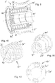
- the Figures 1 to 3 show the pulley decoupler 1, hereinafter referred to as decoupler 1 for short, in different perspective representations, namely as a whole in Figure 1 , in longitudinal section in Figure 2 and as an explosion in Figure 3 .
- a hollow cylindrical belt pulley 2 the outer jacket 3 of which is wrapped by the belt and is profiled in accordance with the poly-V shape of the belt, is driven by the belt in the in Figure 1 indicated direction of rotation.
- the belt pulley 2 is rotatably mounted on a hub 4, which is firmly screwed to the generator shaft.
- the hub 4 has an internal thread (not shown) in the middle section 5 and an internal multi-tooth 6 as an engagement contour for the screwing tool on the front end section remote from the generator.
- the belt pulley 2 is mounted on the hub 4 at the generator-side end radially and axially by means of a roller bearing 7 and at the end remote from the generator radially by means of a plain bearing 8.
- the roller bearing 7 is a single-row ball bearing 7 sealed on both sides
- the plain bearing 8 is a radial bearing ring 8 made of polyamide, which is in direct sliding contact with the inner diameter of the pulley 2.
- the inside diameter of the belt pulley 2 is uniform in the entire axial area between the radial bearing ring 8 and the outer ring of the ball bearing 7 and is therefore accessible to particularly simple and inexpensive turning.
- the belt pulley 4 only has at the end remote from the generator a stepped diameter enlargement 9 into which a protective cap 10 is snapped after the decoupler 1 has been screwed onto the generator shaft.
- the components essential for the function of the decoupler 1 are a one-way clutch 11 designed as a loop belt 11 and a decoupler spring 12 connected in series with the loop belt 11, with regard to the drive torque flow from the belt pulley 2 to the hub 4, which is designed as a helical torsion spring 12.
- the loop band 11 and the helical torsion spring 12 extend coaxially to one another in the direction of the axis of rotation 13 of the decoupler 1, the loop band 11 being arranged radially between the belt pulley 2 and the helical torsion spring 12 and consequently enclosing the helical torsion spring 12.
- Both the right-wound loop tape 11 and the left-wound helical torsion spring 12 are completely cylindrical and have legless ends on both sides which radially expand the loop tape 11 and the helical torsion spring 12 when the drive torque is transmitted.
- the first looping strap end 14 running in the drive torque flow from the pulley 2 is braced against the cylindrical inner jacket 15 of a first sleeve 16 which is rotatably fastened in the pulley 2 by means of a press fit.
- the second loop end 17 running in the drive torque flow from the helical torsion spring 12 is braced against the cylindrical inner jacket 18 of a second sleeve 19, which is rotatably mounted in the first sleeve 16 and whose inner jacket 18 has the same diameter as the inner jacket 15.
- the drive torque introduced by the pulley 2 is introduced into the helical torsion spring 12 exclusively through static friction between the first sleeve 16 and the first loop end 14 on the one hand and between the second loop strap end 17 and the second sleeve 19 on the other hand and transferred from there to the hub 4.
- the belt pulley 2 is therefore a rotated part that is manufactured inexpensively and that does not require heat treatment or coating for the purpose of wear protection, but is only provided with corrosion protection.
- the axial forces of the helical torsion spring 12 acting on the second sleeve 19 are supported on the inner ring of the ball bearing 7 via a sliding bearing ring 20.
- the loop belt 11 When the torque is reversed, the loop belt 11 enables the generator shaft and the hub 4 attached to it to be overtaken with respect to the pulley 2. In this state, the loop belt 11 contracts to its (unloaded) starting diameter and slips in one or both sleeves 16, 19, whereby the torque that can be transmitted in the process to the sliding friction torque between the two slipping contact partners reduced.
- the mutual pivot bearing and structural design of the two sleeves 16 and 19 is shown below in conjunction with the Figures 4 to 6 explained, which show the sleeves 16, 19 as individual parts. Both sleeves 16, 19 are formed in one piece and hardened and / or coated sheet metal parts for the purpose of wear resistance of their surface.
- the first sleeve 16 is stepped twice in diameter, with the generator-side first diameter step 21 serving as an axial stop for the second sleeve 19 at the end and the second diameter step 22 remote from the generator serving as an axial stop for the looping belt 11 at the end.
- the first diameter step 21 is formed, with a uniform outer diameter, by increasing the inner diameter in the area of the pivot bearing section in which the second sleeve 19 is received on its outer casing 23 with a clearance fit.
- the pivot bearing section is penetrated by three openings 24, which are evenly distributed around the circumference, for a tool, which allows unhindered assembly of the loop belt 11 in the first sleeve 16.
- the tool grips through the openings 24 and compresses the loop tape 11 in diameter in order to be able to insert it in a centered manner and without bumping over the first diameter step 21 onto the inner jacket 15 and up to the second diameter step 22 into the first sleeve 16.
- the end section 25 of the first sleeve 16 which extends from the second diameter step 22 in the direction away from the generator, encloses the helical torsion spring 12 with little radial clearance in order to prevent inadmissible expansion of the helical torsion spring 12 under the action of torque in this area.
- the drive-side spring end 26 of the helical torsion spring 12 rests against a spring plate 27 that is fixed against rotation with the second sleeve 19, and the output-side spring end 28 rests against a spring plate 29 that is fixed against rotation with the hub 4.
- the spring plate 27, which is fixed against rotation with the second sleeve 19, is in the present case designed as a sheet metal part that is integral with the second sleeve 19.
- the spring plate 29, which is fixed against rotation with the hub 4 is formed in one piece with the hub 4 and has a circumferential groove 30 on the outer surface, which according to FIG Figure 2 Radial bearing ring 8 running directly in pulley 2 axially encloses.
- the spring plates 27, 29 have the frontal contour of the helical torsion spring 12 axially ramps rising and recessed at circumferential steps 31 and 32 spring contact surfaces 33 and 34.
- the drive torque transmitted from the pulley 2 to the hub 4 is over transmit the pressure contact between the circumferential end faces 35 and 36 of the spring ends 26, 28 and the circumferential steps 31, 32 of the spring plates 27, 29.
- the spring contact surface 33 of the spring plate 27 is formed by circular arc-shaped and circumferentially spaced-apart recesses 37 to 39 in the sheet metal part.
- the spring ends 26, 28 with the spring plates 27, 29 form mutual rotation stops, each of which increases the relative rotation of the spring ends, which increases the circumferential distance between the circumferential end faces 35, 36 of the spring ends 26, 28 and the circumferential steps 31, 32 of the spring plates 27, 29 26, 28 with respect to the spring plates 27, 29 limit.
- the rotary stops enable the transmission of tensile forces to the spring ends 26, 28, so that even when the decoupler 1 is overtaking, the relative circumferential position of the spring ends 26, 28 with respect to the spring plates 27, 29, as in the drive torque, is maintained despite the sliding friction torque then acting transmitting pressure contact is present, not significantly changed.
- the rotary stops comprise rotary latching contours which are formed on the part of the spring plates 27, 29 by projections 40, 41 that rise in a wedge-shaped manner in the direction of the steps 31, 32 and on the part of the spring ends 26, 28 by axial and, in this case, rectangular recesses 42, 43 .
- the wedge shape of the projections 40, 41 enables the spring ends 26, 28 to be applied circumferentially and initially in a non-directional manner to the spring plates 27, 29 and then their low-resistance relative rotation, which takes place until the projections 40, 41 engage in the recesses 42, 43 the circumferential distance between the end faces 35, 36 of the spring ends 26, 28 and the circumferential steps 31, 32 of the spring plates 27, 29 is reduced.
- the projection 40 of the spring plate 27 is formed like the recesses 37 to 39 in the sheet metal part.
- the rotation-locking contours can alternatively also be arranged kinematically reversed, with the projections then on the one hand being part of the spring ends and rising in a wedge shape away from the circumferential steps 31, 32 of the spring plates and on the other hand the spring plates being correspondingly recessed.
- FIGS Figures 9 to 12 show a decoupler 1 'with a pivot bearing not according to the invention of the first sleeve 16' and the second sleeve 19 ', which in this case is rotatably mounted next to the first sleeve 16' and directly in the pulley 2 '.
- the figures nevertheless show structural details that are used in the decoupler 1 according to the invention according to FIGS Figures 1 to 8 can be used alternatively.
- the hub 4 ' is in two parts with a base body and a sheet metal sleeve 44 pressed thereon to form the spring plate 29' which is fixed against rotation with the hub 4 '.
- the circumferential groove 30 on the outer jacket of the one-piece hub 4 in this embodiment the axial edging of the radial bearing ring 8 'is not done by the hub 4', but by means of a retaining ring 45 pressed into the pulley 2 ', which is designed as a shaped sheet metal part with a U-profile.
- the rotary latching contours are not wedge-shaped in this embodiment, but with circular segment-shaped projections 40 ', 41' on the spring plates 27 ', 29' and circular segment-shaped recesses 42 ', 43' in the spring ends 26 ', 28' of the helical torsion spring 12 ' extensively symmetrical.
Description
Die Erfindung betrifft einen Riemenscheibenentkoppler zur Antriebsmomentübertragung vom Riemen eines Nebenaggregate-Riementriebs auf die Welle eines der Nebenaggregate, mit:
- einer Riemenscheibe,
- einer auf der Welle zu befestigenden Nabe
- und einer im Antriebsmomentfluss zwischen der Riemenscheibe und der Nabe angeordneten Reihenschaltung aus einer Entkopplerfeder und einem Schlingband, das sich in Richtung der Drehachse des Riemenscheibenentkopplers erstreckt und radial zwischen der Riemenscheibe und der Entkopplerfeder angeordnet ist und dessen beide
- a pulley,
- a hub to be attached to the shaft
- and a series connection, arranged in the drive torque flow between the belt pulley and the hub, of a decoupler spring and a loop tape, which extends in the direction of the axis of rotation of the belt pulley decoupler and is arranged radially between the belt pulley and the decoupler spring and both of them
Enden sich unter Übertragung des Antriebsmoments radial aufweiten,
wobei sich das im Antriebsmomentfluss seitens der Riemenscheibe verlaufende erste Schlingbandende gegen den Innenmantel einer ersten Hülse verspannt, die in der Riemenscheibe drehbefestigt ist.Ends expand radially while transmitting the drive torque,
wherein the first loop strap end running in the drive torque flow on the part of the belt pulley is braced against the inner jacket of a first sleeve which is rotatably fastened in the belt pulley.
Drehschwingungen und -ungleichförmigkeiten, die von der Kurbelwelle einer Brennkraftmaschine in deren Nebenaggregate-Riementrieb eingeleitet werden, können bekanntlich durch Riemenscheibenentkoppler kompensiert werden, die im Englischen üblicherweise als Decoupler bezeichnet und typischerweise als Generator-Riemenscheibe ausgebildet sind. Das Schlingband dient als Einwegkupplung, die im geschlossenen Zustand das Antriebsmoment von der Riemenscheibe auf die Nabe überträgt, wobei die Elastizität der mit dem Schlingband in Reihe geschalteten Entkopplerfeder die aus dem Riementrieb stammenden Drehungleichförmigkeiten glättet. Bei verzögert rotierender Riemenscheibe öffnet das Schlingband, wobei - dann umgekehrt - kein nennenswertes Drehmoment von der Nabe auf die Riemenscheibe übertragen werden kann, so dass die mit hoher Massenträgheit belastete Generatorwelle die Riemenscheibe überholen kann.Torsional vibrations and irregularities that are introduced from the crankshaft of an internal combustion engine into the belt drive of the ancillary units can, as is known, be compensated for by pulley decouplers, which are usually referred to as decouplers and are typically designed as generator pulleys. The looping belt serves as a one-way clutch which, when closed, transfers the drive torque from the belt pulley to the hub, the elasticity of the decoupling spring connected in series with the looping belt smoothing out the rotational irregularities from the belt drive. When the belt pulley rotates with a delay, the loop belt opens, whereby - then vice versa - no significant torque can be transmitted from the hub to the belt pulley, so that the generator shaft, which is loaded with high inertia, can overtake the belt pulley.
Ein Riemenscheibenentkoppler ohne Schlingband ist aus der
Die
Ein Riemenscheibenentkoppler mit radial innen angeordnetem Schlingband und radial außen angeordneter Entkopplerfeder in Form einer Schraubendrehfeder ist aus der
Ein gattungsgemäßer Riemenscheibenentkoppler mit demgegenüber radial vertauschter Anordnung von Schlingband und Schraubendrehfeder geht beispielsweise aus der
Die Lösung hierfür ergibt sich aus den Merkmalen des Anspruchs 1. Demnach soll sich das im Antriebsmomentfluss seitens der Entkopplerfeder verlaufende zweite Schlingbandende gegen den Innenmantel einer zweiten Hülse verspannen, die in der ersten Hülse drehbar gelagert ist, wobei die erste Hülse und die zweite Hülse einteilig umgeformte und zwecks Verschleißfestigkeit gehärtete und/oder beschichtete Blechteile sind.The solution for this results from the features of claim 1. Accordingly, the second loop strap end running in the drive torque flow on the part of the decoupler spring should be braced against the inner jacket of a second sleeve, which is rotatably mounted in the first sleeve, the first sleeve and the second sleeve in one piece are formed and hardened and / or coated sheet metal parts for the purpose of wear resistance.
Anders als im eingangs zitierten Stand der Technik umfasst der Riemenscheibenentkoppler zwei drehbar ineinander gelagerte Hülsen, in die sich das unter Belastung radial aufweitende Schlingband mit beiden Enden hinein schlingt und das Antriebsmoment überträgt. Folglich können die mit dem Schlingband an- und abtriebseitig gekoppelten Bauteile einfache und kostengünstig herstellbare Kontaktgeometrien für die Schlingbandenden haben. Insbesondere verhindert die drehbare Lagerung der zweiten Hülse in der ersten Hülse den unmittelbaren Kontakt des Schlingbands mit dem Innenmantel der Riemenscheibe, so dass auf eine die Verschleißfestigkeit erhöhende Wärmebehandlung und/oder Oberflächenbeschichtung der Riemenscheibe verzichtet werden kann.In contrast to the prior art cited at the beginning, the belt pulley decoupler comprises two rotatably mounted sleeves into which the loop band, which expands radially under load, loops with both ends and transmits the drive torque. Consequently, the components coupled to the looping belt on the drive and driven side can have contact geometries for the looping belt ends that can be produced in a simple and inexpensive manner. In particular, the rotatable mounting of the second sleeve in the first sleeve prevents direct contact of the loop tape with the inner jacket of the pulley, so that heat treatment and / or surface coating of the pulley that increases wear resistance can be dispensed with.
In der bevorzugten Ausgestaltung eines schenkellosen und folglich vollständig zylindrischen Schlingbands sind die Innenmantelflächen der beiden Hülsen ebenfalls vollständig zylindrisch, so dass das Antriebsmoment ausschließlich durch Reibkontaktkräfte zwischen dem Außenmantel des Schlingbands und dem Innenmantel der beiden Hülsen übertragen wird.In the preferred embodiment of a legless and consequently completely cylindrical loop tape, the inner surface areas of the two sleeves are also completely cylindrical, so that the drive torque is transmitted exclusively by frictional contact forces between the outer surface of the loop tape and the inner surface of the two sleeves.
Beide Hülsen sind kostengünstig herstellbare Blechumformteile, wobei die erste Hülse bevorzugt über einen Pressverband in der Riemenscheibe drehbefestigt ist. Die erste Hülse kann mit einer ersten Durchmesserstufe als Axialanschlag für die zweite Hülse und mit einer zweiten Durchmesserstufe als Axialanschlag für das Schlingband versehen sein.Both sleeves are formed sheet metal parts that can be manufactured inexpensively, the first sleeve preferably being rotatably fastened in the pulley via a press fit. The first sleeve can be provided with a first diameter step as an axial stop for the second sleeve and with a second diameter step as an axial stop for the loop tape.
Diese zweifach im Durchmesser gestufte Hülsengeometrie ermöglicht es, dass der Innendurchmesser der Riemenscheibe im wesentlichen ohne oder allenfalls mit nur kleinen Durchmesserstufen kostengünstig gefertigt (gedreht) werden kann.This sleeve geometry, which is stepped twice in diameter, enables the inside diameter of the belt pulley to be manufactured (turned) cost-effectively without or at most with only small diameter steps.
Für die Montage des Schlingbands in die erste Hülse kann es vorteilhaft sein, dass die erste Hülse mit umfangsverteilten Öffnungen für ein Montagewerkzeug versehen ist. Dieses Werkzeug greift in die Öffnungen ein und verkleinert den Außendurchmesser des Schlingbands, um das Schlingband möglichst widerstandsarm axial über die erste Durchmesserstufe bis hin zur Anlage an der zweiten Durchmesserstufe in die erste Hülse einführen zu können. Die Öffnungen sind in dem Drehlagerabschnitt für die zweite Hülse und zweckmäßigerweise nahe der ersten Durchmesserstufe angeordnet.For the assembly of the loop tape in the first sleeve, it can be advantageous that the first sleeve is provided with circumferentially distributed openings for an assembly tool. This tool engages in the openings and reduces the outer diameter of the loop tape in order to be able to introduce the loop tape axially over the first diameter step up to the second diameter step in the first sleeve with as little resistance as possible. The openings are arranged in the pivot bearing section for the second sleeve and expediently near the first diameter step.
Weitere Merkmale der Erfindung ergeben sich aus der nachfolgenden Beschreibung und aus den Zeichnungen, in denen ein Ausführungsbeispiel und dazu alternative konstruktive Details eines erfindungsgemäßen Riemenscheibenentkopplers für den im Nebenaggregate-Riementrieb einer Brennkraftmaschine angeordneten Generator dargestellt sind. Es zeigen:
- Figur 1
- den Riemenscheibenentkoppler in perspektivischer Gesamtdarstellung;
Figur 2- den Riemenscheibenentkoppler in perspektivischem Längsschnitt;
Figur 3- den Riemenscheibenentkoppler in perspektivisch explodierter Darstellung;
Figur 4- die erste Hülse des Riemenscheibenentkopplers in perspektivischer Einzelteildarstellung;
- Figur 5
- die zweite Hülse des Riemenscheibenentkopplers in perspektivischer außenseitiger Einzelteildarstellung;
- Figur 6
- die zweite Hülse des Riemenscheibenentkopplers in perspektivischer innenseitiger Einzelteildarstellung;
- Figur 7
- die Nabe des Riemenscheibenentkopplers in perspektivischer Einzelteildarstellung;
- Figur 8
- die Entkopplerfeder des Riemenscheibenentkopplers in perspektivischer Einzelteildarstellung;
Figur 9- einen Riemenscheibenentkoppler mit nicht erfindungsgemäßer Drehlagerung der Hülsen in perspektivischem Längsschnitt;
Figur 10- die Nabe des Riemenscheibenentkopplers gemäß
Figur 9 - Figur 11
- die Entkopplerfeder des Riemenscheibenentkopplers gemäß
Figur 9 Figur 12- die zweite Hülse des Riemenscheibenentkopplers gemäß
Figur 9
- Figure 1
- the pulley decoupler in a perspective overall view;
- Figure 2
- the pulley decoupler in perspective longitudinal section;
- Figure 3
- the pulley decoupler in an exploded perspective view;
- Figure 4
- the first sleeve of the pulley decoupler in a perspective detail view;
- Figure 5
- the second sleeve of the pulley decoupler in a perspective view of individual parts;
- Figure 6
- the second sleeve of the pulley decoupler in a perspective interior detail view;
- Figure 7
- the hub of the pulley decoupler in a perspective detail view;
- Figure 8
- the decoupler spring of the pulley decoupler in a perspective detail view;
- Figure 9
- a pulley decoupler with a pivot bearing not according to the invention for the sleeves in a perspective longitudinal section;
- Figure 10
- the hub of the pulley decoupler according to
Figure 9 in perspective detail view; - Figure 11
- the decoupling spring of the pulley decoupling according to
Figure 9 in perspective detail view; - Figure 12
- the second sleeve of the pulley decoupler according to
Figure 9 in perspective view of individual parts on the inside.
Die
Der Innendurchmesser der Riemenscheibe 2 ist im gesamten Axialbereich zwischen dem Radiallagerring 8 und dem Außenring des Kugellagers 7 einheitlich und daher einer besonders einfachen und kostengünstigen Drehbearbeitung zugänglich. Die Riemenscheibe 4 hat lediglich am generatorfernen Ende eine im Durchmesser gestufte Erweiterung 9, in die nach dem Verschrauben des Entkopplers 1 auf die Generatorwelle eine Schutzkappe 10 eingeschnappt wird.The inside diameter of the
Die für die Funktion des Entkopplers 1 wesentlichen Komponenten sind eine als Schlingband 11 ausgebildete Einwegkupplung 11 und eine - bezüglich des Antriebsmomentflusses von der Riemenscheibe 2 auf die Nabe 4 - mit dem Schlingband 11 in Reihe geschaltete Entkopplerfeder 12, die als Schraubendrehfeder 12 ausgebildet ist. Das Schlingband 11 und die Schraubendrehfeder 12 erstrecken sich koaxial zueinander in Richtung der Drehachse 13 des Entkopplers 1, wobei das Schlingband 11 radial zwischen der Riemenscheibe 2 und der Schraubendrehfeder 12 angeordnet ist und folglich die Schraubendrehfeder 12 umschließt.The components essential for the function of the decoupler 1 are a one-way clutch 11 designed as a loop belt 11 and a
Sowohl das rechts gewickelte Schlingband 11 als auch die links gewickelte Schraubendrehfeder 12 sind vollständig zylindrisch und haben beidseitig schenkellose Enden, die das Schlingband 11 bzw. die Schraubendrehfeder 12 bei der Übertragung des Antriebsmoments radial aufweiten. Dabei verspannt sich das im Antriebsmomentfluss seitens der Riemenscheibe 2 verlaufende erste Schlingbandende 14 gegen den zylindrischen Innenmantel 15 einer ersten Hülse 16, die in der Riemenscheibe 2 mittels eines Pressverbands drehbefestigt ist. Das im Antriebsmomentfluss seitens der Schraubendrehfeder 12 verlaufende zweite Schlingbandende 17 verspannt sich gegen den zylindrischen Innenmantel 18 einer zweiten Hülse 19, die in der ersten Hülse 16 drehbar gelagert ist und deren Innenmantel 18 den gleichen Durchmesser wie der Innenmantel 15 hat.Both the right-wound loop tape 11 and the left-wound
Das von der Riemenscheibe 2 eingeleitete Antriebsmoment wird ausschließlich durch Haftreibung zwischen der ersten Hülse 16 und dem ersten Schlingbandende 14 einerseits und zwischen dem zweiten Schlingbandende 17 und der zweiten Hülse 19 andererseits in die Schraubendrehfeder 12 eingeleitet und von dort aus auf die Nabe 4 übertragen. Die Riemenscheibe 2 ist daher ein kostengünstig hergestelltes Drehteil, das zwecks Verschleißschutz eine Wärmebehandlung oder Beschichtung nicht erfordert, sondern lediglich mit einem Korrosionsschutz versehen ist. Die auf die zweite Hülse 19 wirkenden Axialkräfte der Schraubendrehfeder 12 werden über einen Gleitlagerring 20 am Innenring des Kugellagers 7 abgestützt.The drive torque introduced by the
Das Schlingband 11 ermöglicht bei Drehmomentumkehr ein Überholen der Generatorwelle und der darauf befestigten Nabe 4 gegenüber der Riemenscheibe 2. In diesem Zustand zieht sich das Schlingband 11 auf seinen (unbelasteten) Ausgangsdurchmesser zusammen und rutscht in einer oder beiden Hülsen 16, 19 durch, wobei sich das dabei übertragbare Drehmoment auf das Gleitreibmoment zwischen den beiden durchrutschenden Kontaktpartnern reduziert.When the torque is reversed, the loop belt 11 enables the generator shaft and the
Die gegenseitige Drehlagerung und konstruktive Ausgestaltung der beiden Hülsen 16 und 19 wird nachfolgend in Zusammenschau mit den
Der sich von der zweiten Durchmesserstufe 22 in generatorferne Richtung erstreckende Endabschnitt 25 der ersten Hülse 16 umschließt die Schraubendrehfeder 12 mit geringer Radialluft, um in diesem Bereich ein unzulässiges Aufweiten der Schraubendrehfeder 12 unter Drehmomenteinwirkung zu verhindern.The
Wie es in weiterer Zusammenschau mit den
Im antriebsmomentfreien Betriebszustand des Entkopplers 1, in dem die Nabe 4 die Riemenscheibe 2 überholt, führt die Gleitreibung des dann durchrutschenden Schlingbands 11 dazu, dass ein oder beide Federenden 26, 28 der Schraubendrehfeder 12 mit einem Reibmoment beaufschlagt werden, das die Federenden 26, 28 in die Umfangsrichtung der axial ansteigenden Federanlageflächen 33, 34 beaufschlagt. Dieser unerwünschte Rampenhochlauf der Schraubendrehfeder 12 wird durch einen sogenannten Anti-ramp-up Mechanismus verhindert. Dabei bilden die Federenden 26, 28 mit den Federtellern 27, 29 gegenseitige Drehanschläge, die jeweils eine den umfänglichen Abstand zwischen den umfänglichen Stirnseiten 35, 36 der Federenden 26, 28 und den umfänglichen Stufen 31, 32 der Federteller 27, 29 vergrößernde Relativverdrehung der Federenden 26, 28 gegenüber den Federtellern 27, 29 begrenzen. Mit anderen Worten ermöglichen die Drehanschläge die Übertragung von Zugkräften an den Federenden 26, 28, so dass sich auch im Überholbetrieb des Entkopplers 1 trotz des dann wirkenden Gleitreibmoments die relative Umfangsposition der Federenden 26, 28 gegenüber den Federtellern 27, 29, wie sie im Antriebsmoment übertragenden Druckkontakt vorliegt, nicht wesentlich verändert.In the torque-free operating state of the decoupler 1, in which the
Die Drehanschläge umfassen erfindungsgemäß Dreh-Rast-Konturen, die seitens der Federteller 27, 29 durch umfänglich in Richtung der Stufen 31, 32 keilförmig ansteigende Vorsprünge 40, 41 und seitens der Federenden 26, 28 durch axiale und vorliegend rechteckige Aussparungen 42, 43 gebildet sind. Die Keilform der Vorsprünge 40, 41 ermöglicht bei der Montage des Entkopplers 1 ein umfänglich zunächst ungerichtetes Anlegen der Federenden 26, 28 an die Federteller 27, 29 und anschließend deren widerstandsarme Relativverdrehung, die bis zum Verrasten der Vorsprünge 40, 41 in den Aussparungen 42, 43 den umfänglichen Abstand zwischen den Stirnseiten 35, 36 der Federenden 26, 28 und den umfänglichen Stufen 31, 32 der Federteller 27, 29 verkleinert. Der Vorsprung 40 des Federtellers 27 ist wie die Einformungen 37 bis 39 im Blechumformteil angeformt.According to the invention, the rotary stops comprise rotary latching contours which are formed on the part of the
Grundsätzlich können die Dreh-Rast-Konturen alternativ auch kinematisch umgekehrt angeordnet sein, wobei dann einerseits die Vorsprünge Teil der Federenden sind und von den umfänglichen Stufen 31, 32 der Federteller weg keilförmig ansteigen und andererseits die Federteller entsprechend ausgespart sind.In principle, the rotation-locking contours can alternatively also be arranged kinematically reversed, with the projections then on the one hand being part of the spring ends and rising in a wedge shape away from the circumferential steps 31, 32 of the spring plates and on the other hand the spring plates being correspondingly recessed.
Die
Die Nabe 4' ist mit einem Grundkörper und einer darauf aufgepressten Blechhülse 44 zur Bildung des mit der Nabe 4' drehfesten Federtellers 29' zweiteilig. Dies ermöglicht es, die Nabe 4' als Drehteil mit gleichmäßigem Außendurchmesser kostengünstig herzustellen. Gegenüber der Umlaufnut 30 am Außenmantel der einteiligen Nabe 4 erfolgt bei dieser Ausführung die axiale Einfassung des Radiallagerrings 8' nicht seitens der Nabe 4', sondern mittels eines in der Riemenscheibe 2' eingepressten Halterings 45, der mit U-Profil als Blechumformteil ausgebildet ist.The hub 4 'is in two parts with a base body and a
Ein weiteres Detail betrifft die Kontur des Anti-ramp-up Mechanismus'. Die Dreh-Rast-Konturen sind bei dieser Ausführung nicht keilförmig, sondern mit kreissegmentförmigen Vorsprüngen 40', 41' auf den Federtellern 27', 29' und kreissegmentförmigen Aussparungen 42', 43' in den Federenden 26', 28' der Schraubendrehfeder 12' umfänglich symmetrisch.Another detail concerns the contour of the anti-ramp-up mechanism. The rotary latching contours are not wedge-shaped in this embodiment, but with circular segment-shaped projections 40 ', 41' on the spring plates 27 ', 29' and circular segment-shaped recesses 42 ', 43' in the spring ends 26 ', 28' of the helical torsion spring 12 ' extensively symmetrical.
- 11
- Riemenscheibenentkoppler / EntkopplerPulley decoupler / decoupler
- 22
- RiemenscheibePulley
- 33
- Außenmantel der RiemenscheibeOuter jacket of the pulley
- 44th
- Nabehub
- 55
- Mittelabschnitt der NabeCentral section of the hub
- 66th
- InnenvielzahnInternal serration
- 77th
- Wälzlager / KugellagerRolling bearings / ball bearings
- 88th
- Gleitlager / RadiallagerringPlain bearing / radial bearing ring
- 99
- Erweiterungextension
- 1010
- Schutzkappeprotective cap
- 1111
- Einwegkupplung / SchlingbandOne-way clutch / loop tape
- 1212
- Entkopplerfeder / SchraubendrehfederDecoupling spring / helical torsion spring
- 1313th
- DrehachseAxis of rotation
- 1414th
- erstes Schlingbandendefirst loop end
- 1515th
- Innenmantel der ersten HülseInner jacket of the first sleeve
- 1616
- erste Hülsefirst sleeve
- 1717th
- zweites Schlingbandendesecond loop end
- 1818th
- Innenmantel der zweiten HülseInner jacket of the second sleeve
- 1919th
- zweite Hülsesecond sleeve
- 2020th
- GleitlagerringPlain bearing ring
- 2121st
- erste Durchmesserstufefirst diameter stage
- 2222nd
- zweite Durchmesserstufesecond diameter stage
- 2323
- Außenmantel der zweiten HülseOuter jacket of the second sleeve
- 2424
- Öffnungopening
- 2525th
- Endabschnitt der ersten HülseEnd portion of the first sleeve
- 2626th
- antriebseitiges Federendespring end on the drive side
- 2727
- FedertellerSpring plate
- 2828
- abtriebseitiges Federendespring end on output side
- 2929
- FedertellerSpring plate
- 3030th
- UmlaufnutCircumferential groove
- 3131
- Stufestep
- 3232
- Stufestep
- 3333
- FederanlageflächeSpring contact surface
- 3434
- FederanlageflächeSpring contact surface
- 3535
- Stirnseite des FederendesFront of the spring end
- 3636
- Stirnseite des FederendesFront of the spring end
- 3737
- EinformungMolding
- 3838
- EinformungMolding
- 3939
- EinformungMolding
- 4040
- keilförmiger Vorsprungwedge-shaped projection
- 4141
- keilförmiger Vorsprungwedge-shaped projection
- 4242
- axiale Aussparungaxial recess
- 4343
- axiale Aussparungaxial recess
- 4444
- BlechhülseSheet metal sleeve
- 4545
- HalteringRetaining ring
Claims (9)
- A belt pulley decoupler (1) for transmission of drive torque from the belt of an auxiliary unit belt drive to the shaft of one of the auxiliary units, comprising:- a belt pulley (2),- a hub (4, 4') to be secured to the shaft- and a series connection which is arranged in the drive torque flow between the belt pulley (2) and the hub (4, 4') and consists of a decoupler spring (12, 12') and a wrap-around band (11) that extends in the direction of the rotational axis (13) of the belt pulley decoupler (1) and is arranged radially between the belt pulley (2) and the decoupler spring (12, 12') and both ends (14, 17) of which expand radially while transmitting the drive torque,wherein the first end (14) of the wrap-around band, which extends in the drive torque flow on the belt-pulley (2) side, is braced against the inner surface (15) of a first sleeve (16) that is rotationally fixed in the belt pulley (2), characterised in that the second end (17) of the wrap-around band, which extends in the drive torque flow on the decoupler-spring (12, 12') side, is braced against the inner surface (18) of a second sleeve (19) which is rotatably mounted in the first sleeve (16), wherein the first sleeve (16) and the second sleeve (19) are sheet metal parts that are formed in one piece and hardened and/or coated for the purpose of wear-resistance.
- The belt pulley decoupler (1) according to claim 1, characterised in that the first sleeve (16) is provided with a first diameter step (21) as an axial stop for the second sleeve (19) and with a second diameter step (22) as an axial stop for the wrap-around band (11).
- The belt pulley decoupler (1) according to claim 2, characterised in that the first sleeve (16) has circumferentially distributed openings (24) in the pivot bearing portion for the second sleeve (19), for mounting the wrap-around band (11) in the first sleeve (16).
- The belt pulley decoupler (1) according to one of the preceding claims, characterised in that the decoupling spring (12, 12') is a helical torsion spring (12, 12') which extends in the direction of the rotational axis (13) of the belt pulley decoupler (1) and the drive-side spring end (26, 26') of which rests on a spring plate (27, 27') which is rotationally fixed to the second sleeve (19), and the output-side spring end (28, 28') of which rests on a spring plate (29, 29') which is rotationally fixed to the hub (4, 4'), and which transmits the drive torque via the pressure contact between circumferential end faces (35, 36) of the spring ends (26, 26', 28, 28") and circumferential steps (31, 32) of the spring plates (27, 27', 29, 29'), wherein the spring ends (26, 26', 28, 28') form mutual rotary stops with the spring plates (27, 27', 29, 29'), each of said stops limiting a relative rotation of the spring ends (26, 26', 28, 28') relative to the spring plates (27, 27', 29, 29') that increases the circumferential distance between the circumferential end faces (35, 36) of the spring ends (26, 26', 28, 28') and the circumferential steps (31, 32) of the spring plates (27, 27', 29, 29').
- The belt pulley decoupler (1) according to claim 4, characterised in that the rotary stops comprise rotary latching contours which, until latched, enable a relative rotation of the spring ends (26, 26', 28, 28') relative to the spring plates (27, 27', 29, 29') that reduces the circumferential distance between the circumferential end faces (35, 36) of the spring ends (26, 26', 28, 28') and the circumferential steps (31, 32) of the spring plates (27, 27', 29, 29').
- The belt pulley decoupler (1) according to claim 5, characterised in that the rotary latching contours are formed on the spring-plate (27, 29) side by projections (40, 41) which rise circumferentially in a wedge shape, and on the spring-end (26, 28) side by axial recesses (42, 43) in which the projections (40, 41) are latched.
- The belt pulley decoupler (1) according to one of claims 4 to 6, characterised in that the spring plate (29) which is rotationally fixed to the hub (4) is formed in one piece with the hub (4) and has an outer casing with a circumferential groove (30), wherein the hub (4) is rotatably mounted in the belt pulley (2) by means of a slide bearing ring (8) arranged in the circumferential groove (30).
- The belt pulley decoupler (1) according to one of claims 4 to 7, characterised in that the spring plate (27) which is rotationally fixed to the second sleeve (19) is formed in one piece with the second sleeve (19) as a sheet-metal formed part.
- The belt pulley decoupler (1) according to claim 8, characterised in that the sheet metal part has a spring contact surface (33) that rises axially in a ramp-like manner and is formed by circular arc-shaped and circumferentially spaced indents (38, 39, 40) in the sheet-metal formed part.
Applications Claiming Priority (2)
| Application Number | Priority Date | Filing Date | Title |
|---|---|---|---|
| DE102015224608.6A DE102015224608B4 (en) | 2015-12-08 | 2015-12-08 | Pulley decoupler |
| PCT/DE2016/200572 WO2017097299A2 (en) | 2015-12-08 | 2016-12-01 | Belt pulley decoupler |
Publications (2)
| Publication Number | Publication Date |
|---|---|
| EP3387290A2 EP3387290A2 (en) | 2018-10-17 |
| EP3387290B1 true EP3387290B1 (en) | 2020-10-28 |
Family
ID=57708253
Family Applications (1)
| Application Number | Title | Priority Date | Filing Date |
|---|---|---|---|
| EP16820160.6A Active EP3387290B1 (en) | 2015-12-08 | 2016-12-01 | Belt pulley decoupler |
Country Status (7)
| Country | Link |
|---|---|
| US (1) | US10816041B2 (en) |
| EP (1) | EP3387290B1 (en) |
| KR (1) | KR20180090277A (en) |
| DE (1) | DE102015224608B4 (en) |
| ES (1) | ES2837057T3 (en) |
| HU (1) | HUE052915T2 (en) |
| WO (1) | WO2017097299A2 (en) |
Families Citing this family (16)
| Publication number | Priority date | Publication date | Assignee | Title |
|---|---|---|---|---|
| BR112017004585B1 (en) * | 2014-09-10 | 2022-10-11 | Litens Automotive Partnership | DECOUPLER, ACCESSORY DRIVE ARRANGEMENT, AND POWER TRANSFER DEVICE. |
| DE102016211558B4 (en) * | 2016-06-28 | 2019-01-31 | Schaeffler Technologies AG & Co. KG | Riemenscheibenentkoppler |
| US10591042B2 (en) * | 2017-07-28 | 2020-03-17 | GM Global Technology Operations LLC | Damper pulley |
| DE102017118232B4 (en) | 2017-08-10 | 2022-04-14 | Schaeffler Technologies AG & Co. KG | traction clutch |
| DE102017123619B4 (en) * | 2017-10-11 | 2020-01-30 | Vibracoustic Gmbh | bending spring |
| DE102018108426B4 (en) | 2018-04-10 | 2023-08-03 | Schaeffler Technologies AG & Co. KG | Pulley decoupler |
| DE102018108425B4 (en) | 2018-04-10 | 2023-10-12 | Schaeffler Technologies AG & Co. KG | Pulley decoupler |
| JP6661044B2 (en) * | 2018-06-25 | 2020-03-11 | 三ツ星ベルト株式会社 | Pulley structure, slide bearing, and method of manufacturing slide bearing |
| DE102018115179B4 (en) | 2018-06-25 | 2021-02-25 | Schaeffler Technologies AG & Co. KG | Pulley decoupler |
| US11028884B2 (en) * | 2018-07-20 | 2021-06-08 | Gates Corporation | Isolating decoupler |
| DE102019105235B4 (en) * | 2019-03-01 | 2021-08-19 | Schaeffler Technologies AG & Co. KG | Belt drive of an internal combustion engine |
| DE102019108656B4 (en) | 2019-04-03 | 2022-02-03 | Schaeffler Technologies AG & Co. KG | Process for assembling a coil spring |
| DE102019112738B4 (en) * | 2019-05-15 | 2021-02-04 | Schaeffler Technologies AG & Co. KG | Decoupler |
| DE102020122178B3 (en) * | 2020-08-25 | 2021-11-11 | Schaeffler Technologies AG & Co. KG | Pulley decoupler |
| DE102020122175B3 (en) * | 2020-08-25 | 2021-11-11 | Schaeffler Technologies AG & Co. KG | Pulley decoupler |
| US20240084862A1 (en) * | 2021-01-20 | 2024-03-14 | Litens Automotive Partnership | Decoupler with torque-limiting feature to protect components thereof |
Family Cites Families (28)
| Publication number | Priority date | Publication date | Assignee | Title |
|---|---|---|---|---|
| US1766585A (en) * | 1926-03-25 | 1930-06-24 | Saco Lowell Shops | Driving cylinder for spinning frames |
| US1948816A (en) * | 1930-06-20 | 1934-02-27 | Automotive Fan & Bearing Co | Fan bearing |
| US2516829A (en) * | 1949-05-05 | 1950-07-25 | Reeves Pulley Co | Sheet metal expansible pulley |
| US4002081A (en) * | 1976-01-12 | 1977-01-11 | Nagel-Chase Manufacturing Company | Pulley construction |
| US5139463A (en) * | 1991-06-05 | 1992-08-18 | Litens Automotive Partnership | Serpentine drive with coil spring alternator connection |
| US5722909A (en) * | 1995-09-27 | 1998-03-03 | Litens Automotive Partnership | Series type decoupling device |
| PL192880B1 (en) * | 1997-05-07 | 2006-12-29 | Litens Automotive Inc | Serpentinous driving system with an improved drive-on alternator clutch disengaging device |
| US7191880B2 (en) * | 2000-05-31 | 2007-03-20 | Ntn Corporation | Over-running clutch pulley with increased surface microhardness |
| JP2003301860A (en) | 2002-04-12 | 2003-10-24 | Ntn Corp | Spring clutch |
| US7153227B2 (en) * | 2002-04-18 | 2006-12-26 | Litens Automotive | Isolator for alternator pulley |
| KR20120099786A (en) * | 2002-07-26 | 2012-09-11 | 리텐스 오토모티브 파트너쉽 | Decoupler assembly |
| KR101068335B1 (en) * | 2003-02-04 | 2011-09-28 | 리텐스 오토모티브 파트너쉽 | Crankshaft torque modulator |
| BRPI0417395B1 (en) * | 2003-12-09 | 2016-06-07 | Litens Automotive Inc | decoupler assembly to transfer torque between a drive shaft and an endless drive element of an automotive engine |
| WO2006081657A1 (en) * | 2005-02-03 | 2006-08-10 | Litens Automotive Partnership | Torque limited decoupler |
| US7878315B2 (en) * | 2006-04-14 | 2011-02-01 | Ntn Corporation | Spring clutch |
| DE112007002873A5 (en) * | 2006-12-11 | 2009-10-08 | Luk Lamellen Und Kupplungsbau Beteiligungs Kg | Decoupler assembly |
| US7891475B2 (en) * | 2007-10-25 | 2011-02-22 | The Gates Corporation | Isolator decoupler |
| US7892124B2 (en) * | 2008-03-07 | 2011-02-22 | The Gates Corporation | Decoupling isolator |
| US8313400B2 (en) * | 2008-11-13 | 2012-11-20 | The Gates Corporation | Damped isolator |
| US9068608B2 (en) | 2009-09-17 | 2015-06-30 | Gates Corporation | Isolator decoupler |
| DE102009052611B4 (en) * | 2009-11-10 | 2018-06-07 | Schaeffler Technologies AG & Co. KG | Pulley arrangement |
| US8613680B2 (en) | 2010-04-20 | 2013-12-24 | Litens Automotive Partnership | Tensioner with spring damper |
| US9046133B2 (en) * | 2010-11-09 | 2015-06-02 | Litens Automotive Partnership | Decoupler assembly having limited overrunning capability |
| DE102012006285A1 (en) * | 2012-03-29 | 2013-10-02 | Carl Freudenberg Kg | Decoupled pulley |
| BR102012022803B1 (en) | 2012-09-10 | 2017-05-02 | Zen S/A Indústria Metalúrgica | decoupler with freewheel system and vibration damping |
| US9611928B2 (en) * | 2013-06-13 | 2017-04-04 | Zhimin Li | Unidirectional coupling damping pulley |
| CN203413096U (en) | 2013-07-15 | 2014-01-29 | 李志敏 | One-way coupling damping belt pulley |
| US9033832B1 (en) * | 2014-01-23 | 2015-05-19 | Gates Corporation | Isolating decoupler |
-
2015
- 2015-12-08 DE DE102015224608.6A patent/DE102015224608B4/en active Active
-
2016
- 2016-12-01 EP EP16820160.6A patent/EP3387290B1/en active Active
- 2016-12-01 WO PCT/DE2016/200572 patent/WO2017097299A2/en active Application Filing
- 2016-12-01 HU HUE16820160A patent/HUE052915T2/en unknown
- 2016-12-01 KR KR1020187015823A patent/KR20180090277A/en active IP Right Grant
- 2016-12-01 US US15/774,117 patent/US10816041B2/en active Active
- 2016-12-01 ES ES16820160T patent/ES2837057T3/en active Active
Non-Patent Citations (1)
| Title |
|---|
| None * |
Also Published As
| Publication number | Publication date |
|---|---|
| DE102015224608A1 (en) | 2017-06-08 |
| US10816041B2 (en) | 2020-10-27 |
| WO2017097299A2 (en) | 2017-06-15 |
| EP3387290A2 (en) | 2018-10-17 |
| KR20180090277A (en) | 2018-08-10 |
| HUE052915T2 (en) | 2021-05-28 |
| CN108368921A (en) | 2018-08-03 |
| ES2837057T3 (en) | 2021-06-29 |
| DE102015224608B4 (en) | 2021-02-04 |
| US20180328414A1 (en) | 2018-11-15 |
| WO2017097299A3 (en) | 2017-08-03 |
Similar Documents
| Publication | Publication Date | Title |
|---|---|---|
| EP3387290B1 (en) | Belt pulley decoupler | |
| EP3253980B1 (en) | Decoupler | |
| EP3256749B1 (en) | Pulley decoupler | |
| DE102015202531B3 (en) | Riemenscheibenentkoppler | |
| DE60207666T2 (en) | Pulley with one-way clutch | |
| DE102016207930B3 (en) | The wave gear | |
| DE102015205612B3 (en) | Riemenscheibenentkoppler | |
| DE102017119460B3 (en) | The wave gear | |
| DE102016223474B3 (en) | Variable speed gear device for a shaft and vehicle with the Verstellgetriebevorrichtung | |
| WO2018215027A1 (en) | Belt pulley decoupler | |
| DE102016211141B4 (en) | Pulley decoupler | |
| DE102018108426B4 (en) | Pulley decoupler | |
| DE102007018495A1 (en) | Clutch disk assembly | |
| EP3336384B1 (en) | Transmission device | |
| DE102015200267B3 (en) | Riemenscheibenentkoppler | |
| DE102017124544B4 (en) | Pulley decoupler | |
| DE102020105516B3 (en) | Decoupler and accessory belt drive of an internal combustion engine with such a decoupler | |
| EP4042031B1 (en) | Belt pulley decoupler | |
| DE102018109537B4 (en) | Pulley decoupler | |
| DE102018108425B4 (en) | Pulley decoupler | |
| DE102016200352B4 (en) | Pulley decoupler | |
| DE102020122178B3 (en) | Pulley decoupler | |
| DE102020129440B3 (en) | Pulley decoupler | |
| DE102020118374B4 (en) | Pulley decoupler | |
| DE102020122175B3 (en) | Pulley decoupler |
Legal Events
| Date | Code | Title | Description |
|---|---|---|---|
| STAA | Information on the status of an ep patent application or granted ep patent |
Free format text: STATUS: UNKNOWN |
|
| STAA | Information on the status of an ep patent application or granted ep patent |
Free format text: STATUS: THE INTERNATIONAL PUBLICATION HAS BEEN MADE |
|
| PUAI | Public reference made under article 153(3) epc to a published international application that has entered the european phase |
Free format text: ORIGINAL CODE: 0009012 |
|
| STAA | Information on the status of an ep patent application or granted ep patent |
Free format text: STATUS: REQUEST FOR EXAMINATION WAS MADE |
|
| 17P | Request for examination filed |
Effective date: 20180709 |
|
| AK | Designated contracting states |
Kind code of ref document: A2 Designated state(s): AL AT BE BG CH CY CZ DE DK EE ES FI FR GB GR HR HU IE IS IT LI LT LU LV MC MK MT NL NO PL PT RO RS SE SI SK SM TR |
|
| AX | Request for extension of the european patent |
Extension state: BA ME |
|
| DAV | Request for validation of the european patent (deleted) | ||
| DAX | Request for extension of the european patent (deleted) | ||
| GRAP | Despatch of communication of intention to grant a patent |
Free format text: ORIGINAL CODE: EPIDOSNIGR1 |
|
| STAA | Information on the status of an ep patent application or granted ep patent |
Free format text: STATUS: GRANT OF PATENT IS INTENDED |
|
| INTG | Intention to grant announced |
Effective date: 20200630 |
|
| GRAS | Grant fee paid |
Free format text: ORIGINAL CODE: EPIDOSNIGR3 |
|
| GRAA | (expected) grant |
Free format text: ORIGINAL CODE: 0009210 |
|
| STAA | Information on the status of an ep patent application or granted ep patent |
Free format text: STATUS: THE PATENT HAS BEEN GRANTED |
|
| AK | Designated contracting states |
Kind code of ref document: B1 Designated state(s): AL AT BE BG CH CY CZ DE DK EE ES FI FR GB GR HR HU IE IS IT LI LT LU LV MC MK MT NL NO PL PT RO RS SE SI SK SM TR |
|
| REG | Reference to a national code |
Ref country code: GB Ref legal event code: FG4D Free format text: NOT ENGLISH |
|
| REG | Reference to a national code |
Ref country code: CH Ref legal event code: EP |
|
| REG | Reference to a national code |
Ref country code: DE Ref legal event code: R096 Ref document number: 502016011576 Country of ref document: DE |
|
| REG | Reference to a national code |
Ref country code: AT Ref legal event code: REF Ref document number: 1328557 Country of ref document: AT Kind code of ref document: T Effective date: 20201115 |
|
| REG | Reference to a national code |
Ref country code: IE Ref legal event code: FG4D Free format text: LANGUAGE OF EP DOCUMENT: GERMAN |
|
| REG | Reference to a national code |
Ref country code: SK Ref legal event code: T3 Ref document number: E 35984 Country of ref document: SK |
|
| REG | Reference to a national code |
Ref country code: NL Ref legal event code: MP Effective date: 20201028 |
|
| PG25 | Lapsed in a contracting state [announced via postgrant information from national office to epo] |
Ref country code: NO Free format text: LAPSE BECAUSE OF FAILURE TO SUBMIT A TRANSLATION OF THE DESCRIPTION OR TO PAY THE FEE WITHIN THE PRESCRIBED TIME-LIMIT Effective date: 20210128 Ref country code: RS Free format text: LAPSE BECAUSE OF FAILURE TO SUBMIT A TRANSLATION OF THE DESCRIPTION OR TO PAY THE FEE WITHIN THE PRESCRIBED TIME-LIMIT Effective date: 20201028 Ref country code: PT Free format text: LAPSE BECAUSE OF FAILURE TO SUBMIT A TRANSLATION OF THE DESCRIPTION OR TO PAY THE FEE WITHIN THE PRESCRIBED TIME-LIMIT Effective date: 20210301 Ref country code: FI Free format text: LAPSE BECAUSE OF FAILURE TO SUBMIT A TRANSLATION OF THE DESCRIPTION OR TO PAY THE FEE WITHIN THE PRESCRIBED TIME-LIMIT Effective date: 20201028 Ref country code: GR Free format text: LAPSE BECAUSE OF FAILURE TO SUBMIT A TRANSLATION OF THE DESCRIPTION OR TO PAY THE FEE WITHIN THE PRESCRIBED TIME-LIMIT Effective date: 20210129 |
|
| REG | Reference to a national code |
Ref country code: LT Ref legal event code: MG4D |
|
| REG | Reference to a national code |
Ref country code: HU Ref legal event code: AG4A Ref document number: E052915 Country of ref document: HU |
|
| PG25 | Lapsed in a contracting state [announced via postgrant information from national office to epo] |
Ref country code: SE Free format text: LAPSE BECAUSE OF FAILURE TO SUBMIT A TRANSLATION OF THE DESCRIPTION OR TO PAY THE FEE WITHIN THE PRESCRIBED TIME-LIMIT Effective date: 20201028 Ref country code: BG Free format text: LAPSE BECAUSE OF FAILURE TO SUBMIT A TRANSLATION OF THE DESCRIPTION OR TO PAY THE FEE WITHIN THE PRESCRIBED TIME-LIMIT Effective date: 20210128 Ref country code: IS Free format text: LAPSE BECAUSE OF FAILURE TO SUBMIT A TRANSLATION OF THE DESCRIPTION OR TO PAY THE FEE WITHIN THE PRESCRIBED TIME-LIMIT Effective date: 20210228 Ref country code: LV Free format text: LAPSE BECAUSE OF FAILURE TO SUBMIT A TRANSLATION OF THE DESCRIPTION OR TO PAY THE FEE WITHIN THE PRESCRIBED TIME-LIMIT Effective date: 20201028 Ref country code: PL Free format text: LAPSE BECAUSE OF FAILURE TO SUBMIT A TRANSLATION OF THE DESCRIPTION OR TO PAY THE FEE WITHIN THE PRESCRIBED TIME-LIMIT Effective date: 20201028 |
|
| PG25 | Lapsed in a contracting state [announced via postgrant information from national office to epo] |
Ref country code: NL Free format text: LAPSE BECAUSE OF FAILURE TO SUBMIT A TRANSLATION OF THE DESCRIPTION OR TO PAY THE FEE WITHIN THE PRESCRIBED TIME-LIMIT Effective date: 20201028 Ref country code: HR Free format text: LAPSE BECAUSE OF FAILURE TO SUBMIT A TRANSLATION OF THE DESCRIPTION OR TO PAY THE FEE WITHIN THE PRESCRIBED TIME-LIMIT Effective date: 20201028 |
|
| REG | Reference to a national code |
Ref country code: DE Ref legal event code: R097 Ref document number: 502016011576 Country of ref document: DE |
|
| PG25 | Lapsed in a contracting state [announced via postgrant information from national office to epo] |
Ref country code: RO Free format text: LAPSE BECAUSE OF FAILURE TO SUBMIT A TRANSLATION OF THE DESCRIPTION OR TO PAY THE FEE WITHIN THE PRESCRIBED TIME-LIMIT Effective date: 20201028 Ref country code: EE Free format text: LAPSE BECAUSE OF FAILURE TO SUBMIT A TRANSLATION OF THE DESCRIPTION OR TO PAY THE FEE WITHIN THE PRESCRIBED TIME-LIMIT Effective date: 20201028 Ref country code: SM Free format text: LAPSE BECAUSE OF FAILURE TO SUBMIT A TRANSLATION OF THE DESCRIPTION OR TO PAY THE FEE WITHIN THE PRESCRIBED TIME-LIMIT Effective date: 20201028 Ref country code: LT Free format text: LAPSE BECAUSE OF FAILURE TO SUBMIT A TRANSLATION OF THE DESCRIPTION OR TO PAY THE FEE WITHIN THE PRESCRIBED TIME-LIMIT Effective date: 20201028 |
|
| REG | Reference to a national code |
Ref country code: CH Ref legal event code: PL |
|
| PG25 | Lapsed in a contracting state [announced via postgrant information from national office to epo] |
Ref country code: DK Free format text: LAPSE BECAUSE OF FAILURE TO SUBMIT A TRANSLATION OF THE DESCRIPTION OR TO PAY THE FEE WITHIN THE PRESCRIBED TIME-LIMIT Effective date: 20201028 Ref country code: MC Free format text: LAPSE BECAUSE OF FAILURE TO SUBMIT A TRANSLATION OF THE DESCRIPTION OR TO PAY THE FEE WITHIN THE PRESCRIBED TIME-LIMIT Effective date: 20201028 |
|
| PLBE | No opposition filed within time limit |
Free format text: ORIGINAL CODE: 0009261 |
|
| REG | Reference to a national code |
Ref country code: BE Ref legal event code: MM Effective date: 20201231 |
|
| STAA | Information on the status of an ep patent application or granted ep patent |
Free format text: STATUS: NO OPPOSITION FILED WITHIN TIME LIMIT |
|
| 26N | No opposition filed |
Effective date: 20210729 |
|
| PG25 | Lapsed in a contracting state [announced via postgrant information from national office to epo] |
Ref country code: AL Free format text: LAPSE BECAUSE OF FAILURE TO SUBMIT A TRANSLATION OF THE DESCRIPTION OR TO PAY THE FEE WITHIN THE PRESCRIBED TIME-LIMIT Effective date: 20201028 Ref country code: IE Free format text: LAPSE BECAUSE OF NON-PAYMENT OF DUE FEES Effective date: 20201201 Ref country code: LU Free format text: LAPSE BECAUSE OF NON-PAYMENT OF DUE FEES Effective date: 20201201 |
|
| PG25 | Lapsed in a contracting state [announced via postgrant information from national office to epo] |
Ref country code: CH Free format text: LAPSE BECAUSE OF NON-PAYMENT OF DUE FEES Effective date: 20201231 Ref country code: SI Free format text: LAPSE BECAUSE OF FAILURE TO SUBMIT A TRANSLATION OF THE DESCRIPTION OR TO PAY THE FEE WITHIN THE PRESCRIBED TIME-LIMIT Effective date: 20201028 Ref country code: LI Free format text: LAPSE BECAUSE OF NON-PAYMENT OF DUE FEES Effective date: 20201231 |
|
| PG25 | Lapsed in a contracting state [announced via postgrant information from national office to epo] |
Ref country code: IS Free format text: LAPSE BECAUSE OF FAILURE TO SUBMIT A TRANSLATION OF THE DESCRIPTION OR TO PAY THE FEE WITHIN THE PRESCRIBED TIME-LIMIT Effective date: 20210228 Ref country code: TR Free format text: LAPSE BECAUSE OF FAILURE TO SUBMIT A TRANSLATION OF THE DESCRIPTION OR TO PAY THE FEE WITHIN THE PRESCRIBED TIME-LIMIT Effective date: 20201028 Ref country code: MT Free format text: LAPSE BECAUSE OF FAILURE TO SUBMIT A TRANSLATION OF THE DESCRIPTION OR TO PAY THE FEE WITHIN THE PRESCRIBED TIME-LIMIT Effective date: 20201028 Ref country code: CY Free format text: LAPSE BECAUSE OF FAILURE TO SUBMIT A TRANSLATION OF THE DESCRIPTION OR TO PAY THE FEE WITHIN THE PRESCRIBED TIME-LIMIT Effective date: 20201028 |
|
| PG25 | Lapsed in a contracting state [announced via postgrant information from national office to epo] |
Ref country code: MK Free format text: LAPSE BECAUSE OF FAILURE TO SUBMIT A TRANSLATION OF THE DESCRIPTION OR TO PAY THE FEE WITHIN THE PRESCRIBED TIME-LIMIT Effective date: 20201028 |
|
| PG25 | Lapsed in a contracting state [announced via postgrant information from national office to epo] |
Ref country code: BE Free format text: LAPSE BECAUSE OF NON-PAYMENT OF DUE FEES Effective date: 20201231 |
|
| REG | Reference to a national code |
Ref country code: AT Ref legal event code: MM01 Ref document number: 1328557 Country of ref document: AT Kind code of ref document: T Effective date: 20211201 |
|
| PG25 | Lapsed in a contracting state [announced via postgrant information from national office to epo] |
Ref country code: AT Free format text: LAPSE BECAUSE OF NON-PAYMENT OF DUE FEES Effective date: 20211201 |
|
| PGFP | Annual fee paid to national office [announced via postgrant information from national office to epo] |
Ref country code: ES Payment date: 20230228 Year of fee payment: 7 |
|
| PGFP | Annual fee paid to national office [announced via postgrant information from national office to epo] |
Ref country code: DE Payment date: 20230216 Year of fee payment: 7 |
|
| P01 | Opt-out of the competence of the unified patent court (upc) registered |
Effective date: 20230522 |
|
| PGFP | Annual fee paid to national office [announced via postgrant information from national office to epo] |
Ref country code: SK Payment date: 20231129 Year of fee payment: 8 |
|
| PGFP | Annual fee paid to national office [announced via postgrant information from national office to epo] |
Ref country code: GB Payment date: 20231220 Year of fee payment: 8 |
|
| PGFP | Annual fee paid to national office [announced via postgrant information from national office to epo] |
Ref country code: IT Payment date: 20231228 Year of fee payment: 8 Ref country code: HU Payment date: 20231222 Year of fee payment: 8 Ref country code: FR Payment date: 20231222 Year of fee payment: 8 Ref country code: CZ Payment date: 20231124 Year of fee payment: 8 |