EP3386613B1 - Unit for treatment of a bioprocess liquid with disposable flow path elements - Google Patents
Unit for treatment of a bioprocess liquid with disposable flow path elements Download PDFInfo
- Publication number
- EP3386613B1 EP3386613B1 EP16802025.3A EP16802025A EP3386613B1 EP 3386613 B1 EP3386613 B1 EP 3386613B1 EP 16802025 A EP16802025 A EP 16802025A EP 3386613 B1 EP3386613 B1 EP 3386613B1
- Authority
- EP
- European Patent Office
- Prior art keywords
- flow path
- unit
- disposable flow
- disposable
- legs
- Prior art date
- Legal status (The legal status is an assumption and is not a legal conclusion. Google has not performed a legal analysis and makes no representation as to the accuracy of the status listed.)
- Active
Links
Images




Classifications
-
- C—CHEMISTRY; METALLURGY
- C12—BIOCHEMISTRY; BEER; SPIRITS; WINE; VINEGAR; MICROBIOLOGY; ENZYMOLOGY; MUTATION OR GENETIC ENGINEERING
- C12M—APPARATUS FOR ENZYMOLOGY OR MICROBIOLOGY; APPARATUS FOR CULTURING MICROORGANISMS FOR PRODUCING BIOMASS, FOR GROWING CELLS OR FOR OBTAINING FERMENTATION OR METABOLIC PRODUCTS, i.e. BIOREACTORS OR FERMENTERS
- C12M23/00—Constructional details, e.g. recesses, hinges
- C12M23/28—Constructional details, e.g. recesses, hinges disposable or single use
-
- B—PERFORMING OPERATIONS; TRANSPORTING
- B01—PHYSICAL OR CHEMICAL PROCESSES OR APPARATUS IN GENERAL
- B01D—SEPARATION
- B01D15/00—Separating processes involving the treatment of liquids with solid sorbents; Apparatus therefor
- B01D15/08—Selective adsorption, e.g. chromatography
-
- B—PERFORMING OPERATIONS; TRANSPORTING
- B01—PHYSICAL OR CHEMICAL PROCESSES OR APPARATUS IN GENERAL
- B01D—SEPARATION
- B01D61/00—Processes of separation using semi-permeable membranes, e.g. dialysis, osmosis or ultrafiltration; Apparatus, accessories or auxiliary operations specially adapted therefor
- B01D61/14—Ultrafiltration; Microfiltration
- B01D61/18—Apparatus therefor
-
- C—CHEMISTRY; METALLURGY
- C12—BIOCHEMISTRY; BEER; SPIRITS; WINE; VINEGAR; MICROBIOLOGY; ENZYMOLOGY; MUTATION OR GENETIC ENGINEERING
- C12M—APPARATUS FOR ENZYMOLOGY OR MICROBIOLOGY; APPARATUS FOR CULTURING MICROORGANISMS FOR PRODUCING BIOMASS, FOR GROWING CELLS OR FOR OBTAINING FERMENTATION OR METABOLIC PRODUCTS, i.e. BIOREACTORS OR FERMENTERS
- C12M23/00—Constructional details, e.g. recesses, hinges
- C12M23/50—Means for positioning or orientating the apparatus
-
- C—CHEMISTRY; METALLURGY
- C12—BIOCHEMISTRY; BEER; SPIRITS; WINE; VINEGAR; MICROBIOLOGY; ENZYMOLOGY; MUTATION OR GENETIC ENGINEERING
- C12M—APPARATUS FOR ENZYMOLOGY OR MICROBIOLOGY; APPARATUS FOR CULTURING MICROORGANISMS FOR PRODUCING BIOMASS, FOR GROWING CELLS OR FOR OBTAINING FERMENTATION OR METABOLIC PRODUCTS, i.e. BIOREACTORS OR FERMENTERS
- C12M29/00—Means for introduction, extraction or recirculation of materials, e.g. pumps
-
- C—CHEMISTRY; METALLURGY
- C12—BIOCHEMISTRY; BEER; SPIRITS; WINE; VINEGAR; MICROBIOLOGY; ENZYMOLOGY; MUTATION OR GENETIC ENGINEERING
- C12M—APPARATUS FOR ENZYMOLOGY OR MICROBIOLOGY; APPARATUS FOR CULTURING MICROORGANISMS FOR PRODUCING BIOMASS, FOR GROWING CELLS OR FOR OBTAINING FERMENTATION OR METABOLIC PRODUCTS, i.e. BIOREACTORS OR FERMENTERS
- C12M29/00—Means for introduction, extraction or recirculation of materials, e.g. pumps
- C12M29/04—Filters; Permeable or porous membranes or plates, e.g. dialysis
-
- C—CHEMISTRY; METALLURGY
- C12—BIOCHEMISTRY; BEER; SPIRITS; WINE; VINEGAR; MICROBIOLOGY; ENZYMOLOGY; MUTATION OR GENETIC ENGINEERING
- C12M—APPARATUS FOR ENZYMOLOGY OR MICROBIOLOGY; APPARATUS FOR CULTURING MICROORGANISMS FOR PRODUCING BIOMASS, FOR GROWING CELLS OR FOR OBTAINING FERMENTATION OR METABOLIC PRODUCTS, i.e. BIOREACTORS OR FERMENTERS
- C12M41/00—Means for regulation, monitoring, measurement or control, e.g. flow regulation
-
- B—PERFORMING OPERATIONS; TRANSPORTING
- B01—PHYSICAL OR CHEMICAL PROCESSES OR APPARATUS IN GENERAL
- B01D—SEPARATION
- B01D15/00—Separating processes involving the treatment of liquids with solid sorbents; Apparatus therefor
-
- B—PERFORMING OPERATIONS; TRANSPORTING
- B01—PHYSICAL OR CHEMICAL PROCESSES OR APPARATUS IN GENERAL
- B01D—SEPARATION
- B01D2313/00—Details relating to membrane modules or apparatus
- B01D2313/18—Specific valves
-
- B—PERFORMING OPERATIONS; TRANSPORTING
- B01—PHYSICAL OR CHEMICAL PROCESSES OR APPARATUS IN GENERAL
- B01D—SEPARATION
- B01D2313/00—Details relating to membrane modules or apparatus
- B01D2313/58—Parts of membrane modules specifically adapted for single use
Definitions
- the present invention relates to instrumentation for treatment of bioprocess liquids, and more particularly to instrumentation for filtration of bioprocess liquids using disposable flow paths.
- the invention also relates to a method of installing a disposable flow path on an apparatus for filtration of bioprocess liquids.
- Crossflow filtration also referred to a "tangential flow filtration” (TFF)
- CFF Crossflow filtration
- TFF tangential flow filtration
- Various filtration devices e.g. using TFF, are known. See, for example, WO 2011/161609 A1 , GB 1 434 786 A , WO 2013/043433 A2 and US 8,900,454 B2 .
- CFF/TFF membrane processes are microfiltration and ultrafiltration. Such processes may be pressure driven and depend upon the "membrane flux", defined as the flow volume over time per unit area of membrane, across the microfiltration or ultrafiltration membrane. At low pressures, the transmembrane flux is proportional to pressure. As a result, by varying the transmembrane pressure difference driving force and average pore diameter, a membrane may serve as a selective barrier by permitting certain components of a mixture to pass through while retaining others. This results in two phases, the permeate and retentate phases, each of which is enriched in one or more of the components of the mixture. The retentate stream is recirculated in the flow circuitry and is pumped across the membrane again in a continuous fashion.
- Such CFF/TFF systems are used to significantly reduce the volume of the sample solution as a permeate stream is withdrawn from the system. So, the sample solution becomes concentrated when the system is driven in a concentration mode.
- CFF/TFF systems have the advantage that due to the direction of the flow of the fluid sample, which is essentially parallel to the membrane surface, an automatic sweeping and cleansing takes place so that higher fluxes and higher throughputs can often be attained with such systems in relation to corresponding normal flow filtration systems. Further, a large fraction of sample flows continuously over the membrane surface so that a clogging and fouling is discouraged in such systems. With respect to these and other advantages, CFF/TFF systems are often used in industrial and/or biotechnological processes.
- buffer and other system treatment solutions need to circulate through the filter and other system components for equilibration prior or subsequent to the separation process. Ideally, such circulation and equilibration of buffer and other system treatment solutions is performed by an automated method without the need for manual intervention.
- Filtration systems are a critical component of the pharmaceutical and biotechnology industries for purifying bioprocessing liquids. Due to the high value of the purified liquid extensive research has been focused on improving all aspects of the filtration systems. Such filtration systems also cover a broad spectrum of utility including micro-filtration, ultrafiltration, tangential or cross-flow filtration, as well as constant volume diafiltration. Generally, in these systems, the liquid to be filtered is forced through a flow path to a porous membrane sheet or a porous hollow fiber column. Such sheets or membranes are commercially available and utilizing these different pore sizes molecules or particulates smaller than the average membrane or column pore size will pass, together with solvent for example, through the membrane or hollow fiber walls and are collected as filtrate. A retentate flow is left behind.
- One aspect of the invention is to provide a unit for treatment of a bioprocess liquid which allows complete recovery of liquid and facilitates the removal of air from the system. This is achieved with a first unit as defined in claim 1.
- An advantage is that the unit improves the drainage of a disposable flow path mounted on the unit prior to disposal of the flow path. It is always advantageous to to drain while the flow path is in a controlled position, i.e. mounted on the unit, compared to draining a loose flow path after dismounting it from the unit and manually directing the tubing towards a draining point. The latter procedure is not compatible with GMP manufacturing and definition of standard operating procedures necessary in a biopharmaceutical production setting.
- a second aspect of the invention is to provide an apparatus for treatment of a bioprocess liquid which allows complete recovery of liquid and facilitates the removal of air from the system. This is achieved with an apparatus as defined in the claims.
- a third aspect of the invention is to provide a method of installing a disposable flow path on a unit for treatment of a bioprocess liquid. This is achieved with a method as defined in the claims.
- a fourth aspect of the invention is to provide a method of tangential flow filtration of a bioprocess liquid. This is achieved with a method as defined in the claims.
- joinder references e.g., joined, attached, coupled, connected, and the like
- Joinder references are to be construed broadly and may include intermediate members between a connection of elements and relative movement between elements. As such, joinder references do not necessarily imply that two elements are connected directly and in fixed relation to each other. Further, various elements discussed with reference to the various embodiments may be interchanged to create entirely new embodiments coming within the scope of the present invention.
- the present invention discloses a first unit 1 for treatment of a bioprocess liquid, which can e.g. be a filtration unit, such as a tangential flow filtration unit or a dead end filtration unit.
- the first unit can be a chromatography unit or a bioreactor unit.
- the first unit comprises a first lateral face 2, a second lateral face 3 and a front face 4 which meets the two lateral faces.
- the front face and optionally also the lateral faces can be vertically oriented.
- the first unit may comprise or be adapted to receive a filter element 5, e.g. on one of the lateral faces. This filter element may be fluidically connected to a disposable flow path 6.
- the first unit, in particular the front face 4 comprises:
- the plurality of valves and optional pumps and sensors are vertically offset from each other to give one or more legs, such as all legs, of a disposable flow path received by the valves and optional pumps and sensors a slope of at least 4 degrees from the horizontal plane h.
- the slope can be defined as the angle ⁇ between a straight line from one end 23 of a leg 8 to an opposite end 24 of the leg and the horizontal plane h.
- the slope may be 4.0-6.0 degrees from the horizontal plane.
- the slope allows efficient draining of the system, which is essential for the recovery of valuable material after completion of a treatment, e.g. a filtration run, a chromatography run or a cell culture.
- the slope is particularly important when a flow path with lengths of tubing 8 connected by hose barb couplings 9 is used, as the lower inner diameter of the hose barb couplings causes stagnating pools and can trap air bubbles.
- Hose barb couplings are particularly desirable for braided tubing and other types of tubing which is not amenable to connection by welding or molding. We have found that a slope larger than 3 degrees drastically improves the draining, particularly when connectors are used, but also to counteract any slack in flexible flow path legs.
- the volume of the flow path should generally be kept as low as possible to minimize the hold-up volume, thus allowing high concentration factors and low volumes of processed fluid.
- the slopes can suitably be up to 10.0 degrees or up to 8.0 or 6.0 degrees, as higher slopes lead to longer legs. Short branch legs connecting the longer legs may however need to have a higher slope, e.g. about 90 degrees.
- the lateral faces 2 and 3 may comprise a plurality of valves 7 and optional pumps 10/sensors 11 adapted to receive one or more flow path legs 8 in a sloped configuration.
- the first unit further comprises guides 12 on the front face, and optionally one or both of the lateral faces, between the valves and any optional pumps and sensors for installation of the disposable flow path.
- the guides can be essentially linear with slopes of at least 4.0, or 4.0-6.0 degrees from the horizontal plane. They may comprise visually and/or tactilely distinguishable lines, such as e.g. coloured lines 13 or relief lines 14 along which the legs of a disposable flow path can be arranged.
- the guides may also comprise means for restraining a disposable flow path with the desired slope, e.g. pegs 15, ledges 16 and/or recesses 17 adapted to receive the disposable flow path.
- the legs of the disposable flow path can suitably be aligned with the guides, and in case the guides comprise restraining means this can minimize any slack in flexible flow path legs.
- the first unit further comprises a processor 17 with an optical display 18.
- a graphical user interface 25 on the optical display shows an outline of the front face 4 with valves 7, optional pumps 10 and sensors 11 and the flow path 6, with one or more legs 8 of the flow path having a slope of at least 4.0, or 4.0-6.0 degrees from the horizontal plane h.
- the graphical user interface with the slopes visualized is helpful for the user to understand the orientation of the flow path legs. Further it facilitates the programming of methods for draining/recovery and/or air removal with appropriate flow directions. This is particularly important for draining/recovery methods, where the draining flow directions in the flow path may be the reverse of the pump flow directions during the main process operation.
- the first unit is adapted to be juxtaposed by the first lateral face against a second unit 19.
- the first unit can also be adapted to be juxtaposed by the second lateral face against a third unit 20.
- At least one of the second and third units may be adapted to receive a tank, such as a flexible bag 21,22, fluidically connected to the disposable flow path.
- One of the second and third units may e.g. be adapted to receive a feed/retentate tank or bag 21 and the other of the second and third units may e.g. be adapted to receive a permeate tank or bag 22.
- one of the second and third units may be adapted to receive both a feed/retentate tank or bag and a permeate tank or bag.
- the other of the second and third units may e.g. be adapted to receive a filtration element, e.g. a cassette holder for flat sheet filtration cassettes.
- the invention discloses an apparatus 30 for treatment of a bioprocess liquid.
- the apparatus can typically be a filtration apparatus, such as a tangential flow filtration apparatus, but it can also be e.g. a chromatography apparatus.
- This apparatus comprises the first unit 1 as discussed above and at least one of a second 19 and a third 20 unit juxtaposed by the first and/or second lateral faces.
- the apparatus may further comprise one or more of a filtration element 5, a feed/retentate tank or bag 21 and a permeate tank or bag 22, all of which may be fluidically connected by the disposable flow path 6 described above.
- the disposable flow path may comprise a retentate loop received by a retentate pump and fluidically connected with a retentate inlet and a retentate outlet on the filter element.
- the retentate loop can also suitably be fluidically connected with a feed/retentate tank or bag, such as with a feed/retentate tank or bag outlet and a feed/retentate tank or bag inlet.
- the disposable flow path may comprise a permeate line or permeate loop fluidically connected to at least a permeate outlet on the filter element. The permeate line/loop may be received by a permeate pump and fluidically connected to a permeate tank or bag.
- the invention discloses a method of installing a disposable flow path on the first unit as discussed above, comprising receiving the disposable flow path in the valves and optional pumps and sensors, wherein all legs of said disposable flow path have a slope of at least 4.0, degrees from the horizontal plane.
- all legs of said disposable flow path have a slope of at least 4.0, degrees from the horizontal plane.
- one or more legs have a slope of 4.0-6.0 degrees from the horizontal plane.
- the disposable flow path can be supplied presterilized, e.g. sterilized by gamma irradiation. It can be equipped with sanitary connectors for aseptic connection to a filtration element, a feed/retentate tank or bag and a permeate tank or bag.
- the invention discloses a method of tangential flow filtration of a bioprocess liquid, comprising the steps of:
- the method can also comprise, before or during step b), a step a') of letting out any residual air through an air outlet leg of the disposable flow path.
- the air outlet leg may be a branch of the flow path located in a high position and may comprise a sterilization grade filter to prevent contamination of the flow path.
- the method comprises, after step c), a step d) of draining the disposable flow path.
- the draining can e.g. be performed via a draining leg of the disposable flow path.
- This leg can e.g. be a branch of the flow path located in a low position and it may be connected to a drain vessel.
- the method may further comprise a step e) of discarding the disposable flow path. This can e.g. be done by incineration.
Landscapes
- Chemical & Material Sciences (AREA)
- Engineering & Computer Science (AREA)
- Health & Medical Sciences (AREA)
- Wood Science & Technology (AREA)
- Life Sciences & Earth Sciences (AREA)
- Bioinformatics & Cheminformatics (AREA)
- Organic Chemistry (AREA)
- Zoology (AREA)
- Microbiology (AREA)
- Genetics & Genomics (AREA)
- Biomedical Technology (AREA)
- Biotechnology (AREA)
- Biochemistry (AREA)
- General Engineering & Computer Science (AREA)
- General Health & Medical Sciences (AREA)
- Sustainable Development (AREA)
- Water Supply & Treatment (AREA)
- Chemical Kinetics & Catalysis (AREA)
- Analytical Chemistry (AREA)
- Clinical Laboratory Science (AREA)
- External Artificial Organs (AREA)
- Apparatus Associated With Microorganisms And Enzymes (AREA)
- Separation Using Semi-Permeable Membranes (AREA)
Description
- The present invention relates to instrumentation for treatment of bioprocess liquids, and more particularly to instrumentation for filtration of bioprocess liquids using disposable flow paths. The invention also relates to a method of installing a disposable flow path on an apparatus for filtration of bioprocess liquids.
- Crossflow filtration ("CFF" also referred to a "tangential flow filtration" (TFF)) systems are used in industry applications, such as, for example, manufacturing process separations, waste treatment plants and water purification systems where they can extend the lifetime of filtration membranes by removing and/or preventing the build-up of contaminants and promote consistency of the filtration process with time. Various filtration devices, e.g. using TFF, are known. See, for example,
WO 2011/161609 A1 ,GB 1 434 786 AWO 2013/043433 A2 andUS 8,900,454 B2 . - The most commonly used CFF/TFF membrane processes are microfiltration and ultrafiltration. Such processes may be pressure driven and depend upon the "membrane flux", defined as the flow volume over time per unit area of membrane, across the microfiltration or ultrafiltration membrane. At low pressures, the transmembrane flux is proportional to pressure. As a result, by varying the transmembrane pressure difference driving force and average pore diameter, a membrane may serve as a selective barrier by permitting certain components of a mixture to pass through while retaining others. This results in two phases, the permeate and retentate phases, each of which is enriched in one or more of the components of the mixture. The retentate stream is recirculated in the flow circuitry and is pumped across the membrane again in a continuous fashion. Such CFF/TFF systems are used to significantly reduce the volume of the sample solution as a permeate stream is withdrawn from the system. So, the sample solution becomes concentrated when the system is driven in a concentration mode.
- CFF/TFF systems have the advantage that due to the direction of the flow of the fluid sample, which is essentially parallel to the membrane surface, an automatic sweeping and cleansing takes place so that higher fluxes and higher throughputs can often be attained with such systems in relation to corresponding normal flow filtration systems. Further, a large fraction of sample flows continuously over the membrane surface so that a clogging and fouling is discouraged in such systems. With respect to these and other advantages, CFF/TFF systems are often used in industrial and/or biotechnological processes.
- In an automated CFF/TFF system, buffer and other system treatment solutions need to circulate through the filter and other system components for equilibration prior or subsequent to the separation process. Ideally, such circulation and equilibration of buffer and other system treatment solutions is performed by an automated method without the need for manual intervention.
- Filtration systems are a critical component of the pharmaceutical and biotechnology industries for purifying bioprocessing liquids. Due to the high value of the purified liquid extensive research has been focused on improving all aspects of the filtration systems. Such filtration systems also cover a broad spectrum of utility including micro-filtration, ultrafiltration, tangential or cross-flow filtration, as well as constant volume diafiltration. Generally, in these systems, the liquid to be filtered is forced through a flow path to a porous membrane sheet or a porous hollow fiber column. Such sheets or membranes are commercially available and utilizing these different pore sizes molecules or particulates smaller than the average membrane or column pore size will pass, together with solvent for example, through the membrane or hollow fiber walls and are collected as filtrate. A retentate flow is left behind. In many filtration approaches, such as those incorporating ultrafiltration or other tangential-flow filtration devices, the retentate is repeatedly re-circulated with the objective of improving filtration efficiency and enhancing the yield of the filtrate or permeate. Each of these flows contains valuable product up to 1-5% of the total recovery potential. Examples of such systems can be found in
United States Patent 6,607,669 to Schick issued August 19, 2003 ;United States Patent 7,270,744 to Petersen issued September 18, 2007 ;United States Patent 6461513 and International Patent PublicationWO 2014/051503 published April 3, 2014 . - Quantitative recovery of the valuable concentrated bioprocess liquid after purification and or concentration is one area of interest. Once maximal purification and/or concentration processing is complete a significant amount of residual bioprocess liquid remains in the flow path of the filtration system. Numerous strategies have been applied to facilitate recovery of this residual liquid. Unfortunately none of these methods has resulted in the efficient and quantitative recovery of all residual liquid.
- Further, there is a need for removal of air from the flow path during startup of the process, which is not adequately addressed by the current art.
- Accordingly there is a need for further developments to ensure complete recovery of valuable bioprocess liquids as well as complete air removal during startup. This need applies to filtration systems but also to other bioprocess systems, such as e.g. chromatography systems and bioreactors.
- One aspect of the invention is to provide a unit for treatment of a bioprocess liquid which allows complete recovery of liquid and facilitates the removal of air from the system. This is achieved with a first unit as defined in
claim 1. - An advantage is that the unit improves the drainage of a disposable flow path mounted on the unit prior to disposal of the flow path. It is always advantageous to to drain while the flow path is in a controlled position, i.e. mounted on the unit, compared to draining a loose flow path after dismounting it from the unit and manually directing the tubing towards a draining point. The latter procedure is not compatible with GMP manufacturing and definition of standard operating procedures necessary in a biopharmaceutical production setting.
- A second aspect of the invention is to provide an apparatus for treatment of a bioprocess liquid which allows complete recovery of liquid and facilitates the removal of air from the system. This is achieved with an apparatus as defined in the claims.
- A third aspect of the invention is to provide a method of installing a disposable flow path on a unit for treatment of a bioprocess liquid. This is achieved with a method as defined in the claims.
- A fourth aspect of the invention is to provide a method of tangential flow filtration of a bioprocess liquid. This is achieved with a method as defined in the claims.
- Further suitable embodiments of the invention are described in the dependent claims.
-
-
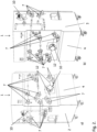
Fig. 1 shows a first unit of the invention (front view). -
Fig. 2 shows an alternative first unit of the invention in perspective views - a) left side + front, b) right side + front. -
Fig. 3 shows three flow path components for use e.g. with the unit ofFig. 2 (schematic drawings with the slopes not shown). a) Feed flow path, b) Retentate flow path, c) Permeate flow path. -
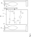
Fig. 4 shows an apparatus of the invention (front view). -
Fig. 5 shows a schematic picture of the slope calculation. -
Fig. 6 shows part of a flow path leg with a hose barb connector. -
Fig. 7 shows different types of guides:- a) Coloured line (side view).
- b) Relief (raised) line (side view).
- c) Pegs (side and front view).
- d) Ledge (side view).
- e) Recess (side view).
-
Fig. 8 shows a processor with a graphical user interface. - To more clearly and concisely describe and point out the subject matter of the claimed invention, the following definitions are provided for specific terms that are used in the following description and the claims appended hereto.
- The singular forms "a" "an" and "the" include plural referents unless the context clearly dictates otherwise. Approximating language, as used herein throughout the specification and claims, may be applied to modify any quantitative representation that could permissibly vary without resulting in a change in the basic function to which it is related. Accordingly, a value modified by a term such as "about" is not to be limited to the precise value specified. Accordingly, unless indicated to the contrary, the numerical parameters set forth in the following specification and attached claims are approximations that may vary depending upon the desired properties sought to be obtained by the embodiments of the present invention. At the very least each numerical parameter should at least be construed in light of the number of reported significant digits and by applying ordinary rounding techniques.
- Any directional terms such as "top", "bottom", "above", "below" "up", "down", "high", "low" and "height" herein refer to the devices as they appear in the drawings. Joinder references (e.g., joined, attached, coupled, connected, and the like) are to be construed broadly and may include intermediate members between a connection of elements and relative movement between elements. As such, joinder references do not necessarily imply that two elements are connected directly and in fixed relation to each other. Further, various elements discussed with reference to the various embodiments may be interchanged to create entirely new embodiments coming within the scope of the present invention.
- In one aspect, illustrated by
Figs. 1-2 , the present invention discloses afirst unit 1 for treatment of a bioprocess liquid, which can e.g. be a filtration unit, such as a tangential flow filtration unit or a dead end filtration unit. Alternatively, the first unit can be a chromatography unit or a bioreactor unit. The first unit comprises a firstlateral face 2, a secondlateral face 3 and afront face 4 which meets the two lateral faces. Suitably, the front face and optionally also the lateral faces can be vertically oriented. The first unit may comprise or be adapted to receive afilter element 5, e.g. on one of the lateral faces. This filter element may be fluidically connected to adisposable flow path 6. The first unit, in particular thefront face 4, comprises: - i) A plurality of
valves 7 adapted to receive and act upon one ormore legs 8 of a disposable flow path, which may at least partly be attached to the front face, e.g. by being received by the valves. The valves can e.g. be pinch valves and the disposable flow path can e.g. comprise lengths offlexible tubing 8 connected byconnectors 9, e.g. hose barb connectors. These connectors can e.g. be two-way connectors or three-way connectors such as Y or T connectors. In a tangential flow filtration system, the disposable flow path can e.g. comprise a feed line, a retentate loop and a permeate loop or line, where the retentate loop and the permeate loop/line are suitably fluidically connected to afilter element 5. The filter element can e.g. be a hollow fiber cartridge or one or more flat sheet membrane cassettes in a cassette holder. The flow path may also comprise additional legs for draining, air removal, and/or cleaning of the system. The flow path is disposable in that it is intended for single use and is composed of low cost plastic and/or elastomeric components suitable for pre-sterilization, e.g. by gamma irradiation. It can e.g. comprise one or more lengths of flexible tubing, such as non-braided tubing for low pressure applications and braided tubing for applications requiring higher pressures. Tubing lengths may be connected by hose barb connectors (e.g. straight connectors, Y or T connectors) and secured e.g. by cable ties or clamps such as Oetiker clamps (Oetiker + Partner AG) or BarbLock fittings (St Gobain). The inner diameter of the tubing can e.g. be 5-25 mm, such as 10-25 mm. The flow path can suitably comprise sanitary or aseptic connectors, e.g. as described inUS 6,679,529 ,US 2009/0015005 orUS 2015/0061282 , in order to allow for aseptic connection of the pre-sterilized flow path to pre-sterilized filtration elements, tanks, bags, further flow paths etc. Examples of flow path components are shown inFig. 3 . The disposable flow path may further comprise at least oneair outlet leg 31 and/or at least one drainingleg 33, where the air outlet leg may be configured for letting out air from the system/flow path and may be located at a high/top position of the flow path. The air outlet leg may further be equipped with asterilization grade filter 32 to prevent contamination of the flow path. The draining leg may be configured for draining the system/flow path and may be located at a low/bottom position of the flow path. - ii) Optionally one or
more pumps 10 adapted to receive and act upon one or more legs of said disposable flow path. The pumps may e.g. be peristaltic pumps or pump drives for disposable pump heads. In the latter case, the disposable pump heads may form part of the disposable flow path and be received by the pump drives on the front face. - iii) Optionally one or
more sensors 11 adapted to receive and to measure one or more parameters in one or more legs of the disposable flow path. The sensors may e.g. be pressure sensors or flow rate sensors but they can also comprise e.g. pH, conductivity or concentration sensors. - The plurality of valves and optional pumps and sensors are vertically offset from each other to give one or more legs, such as all legs, of a disposable flow path received by the valves and optional pumps and sensors a slope of at least 4 degrees from the horizontal plane h. The slope can be defined as the angle α between a straight line from one
end 23 of aleg 8 to anopposite end 24 of the leg and the horizontal plane h. Suitably, the slope may be 4.0-6.0 degrees from the horizontal plane. The slope allows efficient draining of the system, which is essential for the recovery of valuable material after completion of a treatment, e.g. a filtration run, a chromatography run or a cell culture. This also minimizes the amount of liquid discarded with the disposable flow path after use, facilitating incineration of the flow path and reducing the amount of potentially biohazardous material to be handled as waste. Further, removal of air from the system is also facilitated by the slope. The slope is particularly important when a flow path with lengths oftubing 8 connected byhose barb couplings 9 is used, as the lower inner diameter of the hose barb couplings causes stagnating pools and can trap air bubbles. Hose barb couplings are particularly desirable for braided tubing and other types of tubing which is not amenable to connection by welding or molding. We have found that a slope larger than 3 degrees drastically improves the draining, particularly when connectors are used, but also to counteract any slack in flexible flow path legs. The volume of the flow path should generally be kept as low as possible to minimize the hold-up volume, thus allowing high concentration factors and low volumes of processed fluid. Fort this reason, the slopes can suitably be up to 10.0 degrees or up to 8.0 or 6.0 degrees, as higher slopes lead to longer legs. Short branch legs connecting the longer legs may however need to have a higher slope, e.g. about 90 degrees. As illustrated inFig.2 , also one or both of the lateral faces 2 and 3 may comprise a plurality ofvalves 7 andoptional pumps 10/sensors 11 adapted to receive one or moreflow path legs 8 in a sloped configuration. - In some embodiments, illustrated by
Figs. 1 ,2 and7 , the first unit further comprisesguides 12 on the front face, and optionally one or both of the lateral faces, between the valves and any optional pumps and sensors for installation of the disposable flow path. The guides can be essentially linear with slopes of at least 4.0, or 4.0-6.0 degrees from the horizontal plane. They may comprise visually and/or tactilely distinguishable lines, such as e.g.coloured lines 13 orrelief lines 14 along which the legs of a disposable flow path can be arranged. The guides may also comprise means for restraining a disposable flow path with the desired slope, e.g. pegs 15,ledges 16 and/or recesses 17 adapted to receive the disposable flow path. The legs of the disposable flow path can suitably be aligned with the guides, and in case the guides comprise restraining means this can minimize any slack in flexible flow path legs. During use, single use systems for treatment of bioprocess liquids require frequent installation and removal of the flow paths. This is greatly facilitated by the presence of guides. - In certain embodiments, illustrated by
Fig 8 , the first unit (or theapparatus 30 as discussed below) further comprises aprocessor 17 with anoptical display 18. Agraphical user interface 25 on the optical display shows an outline of thefront face 4 withvalves 7,optional pumps 10 andsensors 11 and theflow path 6, with one ormore legs 8 of the flow path having a slope of at least 4.0, or 4.0-6.0 degrees from the horizontal plane h. The graphical user interface with the slopes visualized is helpful for the user to understand the orientation of the flow path legs. Further it facilitates the programming of methods for draining/recovery and/or air removal with appropriate flow directions. This is particularly important for draining/recovery methods, where the draining flow directions in the flow path may be the reverse of the pump flow directions during the main process operation. - In some embodiments, illustrated by
Fig. 4 , the first unit is adapted to be juxtaposed by the first lateral face against asecond unit 19. The first unit can also be adapted to be juxtaposed by the second lateral face against athird unit 20. At least one of the second and third units may be adapted to receive a tank, such as aflexible bag bag 21 and the other of the second and third units may e.g. be adapted to receive a permeate tank orbag 22. Alternatively, one of the second and third units may be adapted to receive both a feed/retentate tank or bag and a permeate tank or bag. The other of the second and third units may e.g. be adapted to receive a filtration element, e.g. a cassette holder for flat sheet filtration cassettes. - In a second aspect, illustrated by
Fig. 4 , the invention discloses anapparatus 30 for treatment of a bioprocess liquid. The apparatus can typically be a filtration apparatus, such as a tangential flow filtration apparatus, but it can also be e.g. a chromatography apparatus. This apparatus comprises thefirst unit 1 as discussed above and at least one of a second 19 and a third 20 unit juxtaposed by the first and/or second lateral faces. The apparatus may further comprise one or more of afiltration element 5, a feed/retentate tank orbag 21 and a permeate tank orbag 22, all of which may be fluidically connected by thedisposable flow path 6 described above. The disposable flow path may comprise a retentate loop received by a retentate pump and fluidically connected with a retentate inlet and a retentate outlet on the filter element. The retentate loop can also suitably be fluidically connected with a feed/retentate tank or bag, such as with a feed/retentate tank or bag outlet and a feed/retentate tank or bag inlet. Further, the disposable flow path may comprise a permeate line or permeate loop fluidically connected to at least a permeate outlet on the filter element. The permeate line/loop may be received by a permeate pump and fluidically connected to a permeate tank or bag. - In a third aspect, the invention discloses a method of installing a disposable flow path on the first unit as discussed above, comprising receiving the disposable flow path in the valves and optional pumps and sensors, wherein all legs of said disposable flow path have a slope of at least 4.0, degrees from the horizontal plane. Suitably, one or more legs have a slope of 4.0-6.0 degrees from the horizontal plane. The disposable flow path can be supplied presterilized, e.g. sterilized by gamma irradiation. It can be equipped with sanitary connectors for aseptic connection to a filtration element, a feed/retentate tank or bag and a permeate tank or bag. Alternatively, it can comprise lengths of tubing for sterile welding to tubing extending from the filtration element, feed/retentate tank/bag and or permeate tank/bag. In a fourth aspect, the invention discloses a method of tangential flow filtration of a bioprocess liquid, comprising the steps of:
- a) providing the apparatus as discussed above;
- b) circulating the liquid from the feed/retentate tank or bag through a retentate loop of the disposable flow path and the filtration element and back to the feed/retentate tank or bag;
- c) conveying a permeate from the filtration element through a permeate line or permeate loop of the disposable flow path either to the permeate tank or bag or to a drain.
- The method can also comprise, before or during step b), a step a') of letting out any residual air through an air outlet leg of the disposable flow path. The air outlet leg may be a branch of the flow path located in a high position and may comprise a sterilization grade filter to prevent contamination of the flow path.
- In some embodiments, the method comprises, after step c), a step d) of draining the disposable flow path. The draining can e.g. be performed via a draining leg of the disposable flow path. This leg can e.g. be a branch of the flow path located in a low position and it may be connected to a drain vessel. After the draining step d), the method may further comprise a step e) of discarding the disposable flow path. This can e.g. be done by incineration.
- This written description uses examples to disclose the invention, including the preferred mode, and also to enable any person skilled in the art to practice the invention, including making and using any devices or systems and performing any incorporated methods. The patentable scope of the invention is defined by the appended claims.
Claims (14)
- A first unit (1) for treatment of a bioprocess liquid comprising a first lateral face (2), a second lateral face (3) and a front face (4) which meets the two said lateral faces; said front face comprising:- a plurality of valves (7) adapted to receive and act upon one or more legs (8) of a disposable flow path (6);- optionally one or more pumps (10) adapted to receive and act upon one or more legs of said disposable flow path;- optionally one or more sensors (11) adapted to receive and to measure one or more parameters in one or more legs of said disposable flow path; characterised in that:- said plurality of valves and optional pumps and sensors are vertically offset from each other to give all legs of a disposable flow path received by said valves and optional pumps and sensors a slope of at least 4.0 degrees from the horizontal plane (h),wherein the unit comprises a disposable flow path with legs connected by hose barb couplings (9), said first unit (1) further comprising guides (12) on said front face between said valves and optional pumps and sensors for installation of said disposable flow path, wherein said guides (12) are essentially linear with slopes of at least 4.0 degrees from the horizontal plane.
- The first unit (1) of claim 1:a) further adapted to receive a filter element (5) fluidically connected to said disposable flow path;b) wherein said plurality of valves comprises one or more pinch valves;c) wherein said one or more pumps comprise a peristaltic pump;d) which is a tangential flow filtration unit;e) which is a chromatography unit; and/orf) which is a bioreactor.
- The first unit (1) of any preceding claim, wherein said guides (12) comprise:a) visually and/or tactilely distinguishable lines (13; 14); and/orb) pegs (15), ledges (16) and/or recesses (17) adapted to receive said disposable flow path.
- The first unit (1) of any preceding claim, further comprising a processor (17) with an optical display (18), wherein a graphical user interface (19) on said optical display shows an outline of said front face with valves, optional pumps and sensors and the flow path, with all legs of said flow path having a slope of at least 4.0 degrees from the horizontal plane.
- The first unit (1) of any preceding claim, adapted to be juxtaposed by the first lateral face against a second unit (19) and optionally to be juxtaposed by the second lateral face against a third unit (20).
- The first unit (1) of claim 1, wherein the legs of said flow path are aligned with the guides (12).
- The first unit (1) of claim 6, wherein said disposable flow path comprises at least one air outlet leg (31) and/or at least one draining leg (33).
- An apparatus for treatment of a bioprocess liquid, comprising the first unit (1) of any preceding claim and at least one of a second and a third unit juxtaposed by the first and/or second lateral faces.
- The apparatus of claim 8, wherein said disposable flow path provides fluidical connection between a filtration element and at least one of a feed/retentate tank or bag and a permeate tank or bag.
- A method of installing a disposable flow path on the first unit (1) of any one of claims 1-7, comprising receiving said disposable flow path in said valves and optional pumps and sensors, wherein all legs of said disposable flow path have a slope of at least 4 degrees from the horizontal plane.
- The method of claim 10, wherein:a) said disposable flow path comprises at least one air outlet leg (31) and/or at least one draining leg (33);b) the legs of said flow path are aligned with the guides (12); and/orc) said disposable flow path is presterilized.
- A method of tangential flow filtration of a bioprocess liquid comprising the steps of:a) providing the apparatus of claim 8 or 9;b) circulating said liquid from said feed/retentate tank or bag through a retentate loop of said disposable flow path and said filtration element and back to said feed/retentate tank or bag;c) conveying a permeate from said filtration element through a permeate line or permeate loop of said disposable flow path either to said permeate tank or bag or to a drain.
- The method of claim 12, comprising, before or during step b), a step a') of letting out residual air through an air outlet leg of said disposable flow path.
- The method of claim 12 or 13, comprising, after step c), a step d) of draining said disposable flow path, and optionally, after step d), a step e) of discarding said disposable flow path.
Applications Claiming Priority (2)
| Application Number | Priority Date | Filing Date | Title |
|---|---|---|---|
| IN3975DE2015 | 2015-12-07 | ||
| PCT/EP2016/078760 WO2017097604A1 (en) | 2015-12-07 | 2016-11-25 | Unit for treatment of a bioprocess liquid with disposable flow path elements |
Publications (2)
| Publication Number | Publication Date |
|---|---|
| EP3386613A1 EP3386613A1 (en) | 2018-10-17 |
| EP3386613B1 true EP3386613B1 (en) | 2025-05-21 |
Family
ID=57421841
Family Applications (1)
| Application Number | Title | Priority Date | Filing Date |
|---|---|---|---|
| EP16802025.3A Active EP3386613B1 (en) | 2015-12-07 | 2016-11-25 | Unit for treatment of a bioprocess liquid with disposable flow path elements |
Country Status (4)
| Country | Link |
|---|---|
| US (1) | US11466241B2 (en) |
| EP (1) | EP3386613B1 (en) |
| CN (3) | CN121911237A (en) |
| WO (1) | WO2017097604A1 (en) |
Families Citing this family (4)
| Publication number | Priority date | Publication date | Assignee | Title |
|---|---|---|---|---|
| GB201717652D0 (en) * | 2017-10-26 | 2017-12-13 | Ge Healthcare Bio Sciences Ab | Bioprocess System |
| EP3841371B1 (en) | 2018-08-21 | 2024-04-17 | Battelle Memorial Institute | Extraction of materials from liquids |
| GB201914176D0 (en) * | 2019-10-01 | 2019-11-13 | Ge Healthcare Bio Sciences Ab | A bioprocess system |
| WO2026013277A1 (en) * | 2024-07-12 | 2026-01-15 | Univercells Technologies Sa | Unit and method for executing a bioprocessing step |
Citations (1)
| Publication number | Priority date | Publication date | Assignee | Title |
|---|---|---|---|---|
| US8900454B2 (en) * | 2010-06-08 | 2014-12-02 | Emd Millipore Corporation | Device for a biological liquid treatment installation |
Family Cites Families (12)
| Publication number | Priority date | Publication date | Assignee | Title |
|---|---|---|---|---|
| GB1434786A (en) | 1973-04-02 | 1976-05-05 | Lichtenstein E S | Apparatus including disposable array for processing body fluids |
| US5439448A (en) * | 1993-01-19 | 1995-08-08 | Datascope Investment Corp. | Bubble-free connector for liquid carrying tubing |
| US5312352A (en) * | 1993-01-19 | 1994-05-17 | Datascope Investment Corp. | Bubble-free connector for liquid carrying tubing |
| US6461513B1 (en) | 2000-05-19 | 2002-10-08 | Filtration Solutions, Inc. | Secondary-flow enhanced filtration system |
| US6607669B2 (en) | 2000-06-23 | 2003-08-19 | Scilog, Inc. | Method and apparatus for enhancing filtration yields in tangential flow filtration |
| US6890316B2 (en) * | 2002-04-25 | 2005-05-10 | Cardiovention, Inc. | Tubing set for blood handling system and methods of use |
| US8888141B2 (en) * | 2009-10-30 | 2014-11-18 | Caterpillar Inc. | Fluid coupling assembly and method of manufacture |
| FR2961713B1 (en) * | 2010-06-23 | 2012-08-10 | Millipore Corp | POCKET FOR CIRCUIT OF A BIOLOGICAL LIQUID TREATMENT FACILITY |
| EP2720730B1 (en) | 2011-09-22 | 2017-01-11 | Fenwal, Inc. | Disposable fluid circuits and methods for cell washing |
| DE102011084027A1 (en) * | 2011-10-05 | 2013-04-11 | Maquet Cardiopulmonary Ag | Quick coupling device |
| JP6321661B2 (en) | 2012-09-27 | 2018-05-09 | ジーイー・ヘルスケア・バイオサイエンス・アクチボラグ | Tangential flow perfusion system and method |
| CN104897885A (en) * | 2015-04-25 | 2015-09-09 | 王超 | All-round medical examination apparatus |
-
2016
- 2016-11-25 EP EP16802025.3A patent/EP3386613B1/en active Active
- 2016-11-25 US US15/781,217 patent/US11466241B2/en active Active
- 2016-11-25 CN CN202610284127.3A patent/CN121911237A/en active Pending
- 2016-11-25 WO PCT/EP2016/078760 patent/WO2017097604A1/en not_active Ceased
- 2016-11-25 CN CN201680071381.XA patent/CN108290116A/en active Pending
- 2016-11-25 CN CN202610284128.8A patent/CN121891931A/en active Pending
Patent Citations (1)
| Publication number | Priority date | Publication date | Assignee | Title |
|---|---|---|---|---|
| US8900454B2 (en) * | 2010-06-08 | 2014-12-02 | Emd Millipore Corporation | Device for a biological liquid treatment installation |
Also Published As
| Publication number | Publication date |
|---|---|
| WO2017097604A1 (en) | 2017-06-15 |
| CN121891931A (en) | 2026-04-21 |
| CN121911237A (en) | 2026-04-24 |
| US11466241B2 (en) | 2022-10-11 |
| US20210017482A1 (en) | 2021-01-21 |
| CN108290116A (en) | 2018-07-17 |
| EP3386613A1 (en) | 2018-10-17 |
Similar Documents
| Publication | Publication Date | Title |
|---|---|---|
| EP3337598B1 (en) | Re-circulation loop in cff/tff single use flow path | |
| US11617988B2 (en) | Single-pass filtration systems and processes | |
| EP3185996B1 (en) | Single pass tangential flow filtration systems and tangential flow filtration systems with recirculation of retentate | |
| US11466241B2 (en) | Unit for treatment of a bioprocess liquid | |
| EP2852454B1 (en) | Filtration apparatus | |
| US11680239B2 (en) | Filter for mammalian cell culture perfusion and clarification with hydrophobic hollow fiber | |
| EP2957335B1 (en) | Single-pass filtration systems and processes | |
| EP4144434B1 (en) | Single-pass filtration systems and processes |
Legal Events
| Date | Code | Title | Description |
|---|---|---|---|
| STAA | Information on the status of an ep patent application or granted ep patent |
Free format text: STATUS: UNKNOWN |
|
| STAA | Information on the status of an ep patent application or granted ep patent |
Free format text: STATUS: THE INTERNATIONAL PUBLICATION HAS BEEN MADE |
|
| PUAI | Public reference made under article 153(3) epc to a published international application that has entered the european phase |
Free format text: ORIGINAL CODE: 0009012 |
|
| STAA | Information on the status of an ep patent application or granted ep patent |
Free format text: STATUS: REQUEST FOR EXAMINATION WAS MADE |
|
| 17P | Request for examination filed |
Effective date: 20180709 |
|
| AK | Designated contracting states |
Kind code of ref document: A1 Designated state(s): AL AT BE BG CH CY CZ DE DK EE ES FI FR GB GR HR HU IE IS IT LI LT LU LV MC MK MT NL NO PL PT RO RS SE SI SK SM TR |
|
| AX | Request for extension of the european patent |
Extension state: BA ME |
|
| DAV | Request for validation of the european patent (deleted) | ||
| DAX | Request for extension of the european patent (deleted) | ||
| STAA | Information on the status of an ep patent application or granted ep patent |
Free format text: STATUS: EXAMINATION IS IN PROGRESS |
|
| 17Q | First examination report despatched |
Effective date: 20200219 |
|
| RAP1 | Party data changed (applicant data changed or rights of an application transferred) |
Owner name: CYTIVA SWEDEN AB |
|
| P01 | Opt-out of the competence of the unified patent court (upc) registered |
Effective date: 20230526 |
|
| GRAP | Despatch of communication of intention to grant a patent |
Free format text: ORIGINAL CODE: EPIDOSNIGR1 |
|
| STAA | Information on the status of an ep patent application or granted ep patent |
Free format text: STATUS: GRANT OF PATENT IS INTENDED |
|
| INTG | Intention to grant announced |
Effective date: 20250130 |
|
| GRAS | Grant fee paid |
Free format text: ORIGINAL CODE: EPIDOSNIGR3 |
|
| GRAA | (expected) grant |
Free format text: ORIGINAL CODE: 0009210 |
|
| STAA | Information on the status of an ep patent application or granted ep patent |
Free format text: STATUS: THE PATENT HAS BEEN GRANTED |
|
| AK | Designated contracting states |
Kind code of ref document: B1 Designated state(s): AL AT BE BG CH CY CZ DE DK EE ES FI FR GB GR HR HU IE IS IT LI LT LU LV MC MK MT NL NO PL PT RO RS SE SI SK SM TR |
|
| REG | Reference to a national code |
Ref country code: GB Ref legal event code: FG4D |
|
| REG | Reference to a national code |
Ref country code: CH Ref legal event code: EP |
|
| REG | Reference to a national code |
Ref country code: DE Ref legal event code: R096 Ref document number: 602016092320 Country of ref document: DE |
|
| REG | Reference to a national code |
Ref country code: IE Ref legal event code: FG4D |
|
| REG | Reference to a national code |
Ref country code: NL Ref legal event code: FP |
|
| PG25 | Lapsed in a contracting state [announced via postgrant information from national office to epo] |
Ref country code: PT Free format text: LAPSE BECAUSE OF FAILURE TO SUBMIT A TRANSLATION OF THE DESCRIPTION OR TO PAY THE FEE WITHIN THE PRESCRIBED TIME-LIMIT Effective date: 20250922 Ref country code: ES Free format text: LAPSE BECAUSE OF FAILURE TO SUBMIT A TRANSLATION OF THE DESCRIPTION OR TO PAY THE FEE WITHIN THE PRESCRIBED TIME-LIMIT Effective date: 20250521 Ref country code: FI Free format text: LAPSE BECAUSE OF FAILURE TO SUBMIT A TRANSLATION OF THE DESCRIPTION OR TO PAY THE FEE WITHIN THE PRESCRIBED TIME-LIMIT Effective date: 20250521 |
|
| REG | Reference to a national code |
Ref country code: LT Ref legal event code: MG9D |
|
| PG25 | Lapsed in a contracting state [announced via postgrant information from national office to epo] |
Ref country code: NO Free format text: LAPSE BECAUSE OF FAILURE TO SUBMIT A TRANSLATION OF THE DESCRIPTION OR TO PAY THE FEE WITHIN THE PRESCRIBED TIME-LIMIT Effective date: 20250821 Ref country code: GR Free format text: LAPSE BECAUSE OF FAILURE TO SUBMIT A TRANSLATION OF THE DESCRIPTION OR TO PAY THE FEE WITHIN THE PRESCRIBED TIME-LIMIT Effective date: 20250822 |
|
| PG25 | Lapsed in a contracting state [announced via postgrant information from national office to epo] |
Ref country code: PL Free format text: LAPSE BECAUSE OF FAILURE TO SUBMIT A TRANSLATION OF THE DESCRIPTION OR TO PAY THE FEE WITHIN THE PRESCRIBED TIME-LIMIT Effective date: 20250521 |
|
| PG25 | Lapsed in a contracting state [announced via postgrant information from national office to epo] |
Ref country code: BG Free format text: LAPSE BECAUSE OF FAILURE TO SUBMIT A TRANSLATION OF THE DESCRIPTION OR TO PAY THE FEE WITHIN THE PRESCRIBED TIME-LIMIT Effective date: 20250521 |
|
| PG25 | Lapsed in a contracting state [announced via postgrant information from national office to epo] |
Ref country code: HR Free format text: LAPSE BECAUSE OF FAILURE TO SUBMIT A TRANSLATION OF THE DESCRIPTION OR TO PAY THE FEE WITHIN THE PRESCRIBED TIME-LIMIT Effective date: 20250521 |
|
| PG25 | Lapsed in a contracting state [announced via postgrant information from national office to epo] |
Ref country code: RS Free format text: LAPSE BECAUSE OF FAILURE TO SUBMIT A TRANSLATION OF THE DESCRIPTION OR TO PAY THE FEE WITHIN THE PRESCRIBED TIME-LIMIT Effective date: 20250821 |
|
| PG25 | Lapsed in a contracting state [announced via postgrant information from national office to epo] |
Ref country code: IS Free format text: LAPSE BECAUSE OF FAILURE TO SUBMIT A TRANSLATION OF THE DESCRIPTION OR TO PAY THE FEE WITHIN THE PRESCRIBED TIME-LIMIT Effective date: 20250921 |
|
| PG25 | Lapsed in a contracting state [announced via postgrant information from national office to epo] |
Ref country code: LV Free format text: LAPSE BECAUSE OF FAILURE TO SUBMIT A TRANSLATION OF THE DESCRIPTION OR TO PAY THE FEE WITHIN THE PRESCRIBED TIME-LIMIT Effective date: 20250521 |
|
| PGFP | Annual fee paid to national office [announced via postgrant information from national office to epo] |
Ref country code: NL Payment date: 20251124 Year of fee payment: 10 |
|
| REG | Reference to a national code |
Ref country code: AT Ref legal event code: MK05 Ref document number: 1796330 Country of ref document: AT Kind code of ref document: T Effective date: 20250521 |
|
| PGFP | Annual fee paid to national office [announced via postgrant information from national office to epo] |
Ref country code: DE Payment date: 20251126 Year of fee payment: 10 |
|
| PGFP | Annual fee paid to national office [announced via postgrant information from national office to epo] |
Ref country code: GB Payment date: 20251125 Year of fee payment: 10 |
|
| PG25 | Lapsed in a contracting state [announced via postgrant information from national office to epo] |
Ref country code: AT Free format text: LAPSE BECAUSE OF FAILURE TO SUBMIT A TRANSLATION OF THE DESCRIPTION OR TO PAY THE FEE WITHIN THE PRESCRIBED TIME-LIMIT Effective date: 20250521 Ref country code: DK Free format text: LAPSE BECAUSE OF FAILURE TO SUBMIT A TRANSLATION OF THE DESCRIPTION OR TO PAY THE FEE WITHIN THE PRESCRIBED TIME-LIMIT Effective date: 20250521 Ref country code: SM Free format text: LAPSE BECAUSE OF FAILURE TO SUBMIT A TRANSLATION OF THE DESCRIPTION OR TO PAY THE FEE WITHIN THE PRESCRIBED TIME-LIMIT Effective date: 20250521 |
|
| PGFP | Annual fee paid to national office [announced via postgrant information from national office to epo] |
Ref country code: FR Payment date: 20251125 Year of fee payment: 10 |
|
| PG25 | Lapsed in a contracting state [announced via postgrant information from national office to epo] |
Ref country code: CZ Free format text: LAPSE BECAUSE OF FAILURE TO SUBMIT A TRANSLATION OF THE DESCRIPTION OR TO PAY THE FEE WITHIN THE PRESCRIBED TIME-LIMIT Effective date: 20250521 |
|
| PG25 | Lapsed in a contracting state [announced via postgrant information from national office to epo] |
Ref country code: EE Free format text: LAPSE BECAUSE OF FAILURE TO SUBMIT A TRANSLATION OF THE DESCRIPTION OR TO PAY THE FEE WITHIN THE PRESCRIBED TIME-LIMIT Effective date: 20250521 |
|
| PG25 | Lapsed in a contracting state [announced via postgrant information from national office to epo] |
Ref country code: SK Free format text: LAPSE BECAUSE OF FAILURE TO SUBMIT A TRANSLATION OF THE DESCRIPTION OR TO PAY THE FEE WITHIN THE PRESCRIBED TIME-LIMIT Effective date: 20250521 Ref country code: RO Free format text: LAPSE BECAUSE OF FAILURE TO SUBMIT A TRANSLATION OF THE DESCRIPTION OR TO PAY THE FEE WITHIN THE PRESCRIBED TIME-LIMIT Effective date: 20250521 |
|
| PG25 | Lapsed in a contracting state [announced via postgrant information from national office to epo] |
Ref country code: IT Free format text: LAPSE BECAUSE OF FAILURE TO SUBMIT A TRANSLATION OF THE DESCRIPTION OR TO PAY THE FEE WITHIN THE PRESCRIBED TIME-LIMIT Effective date: 20250521 |
|
| REG | Reference to a national code |
Ref country code: DE Ref legal event code: R097 Ref document number: 602016092320 Country of ref document: DE |
|
| PLBE | No opposition filed within time limit |
Free format text: ORIGINAL CODE: 0009261 |
|
| STAA | Information on the status of an ep patent application or granted ep patent |
Free format text: STATUS: NO OPPOSITION FILED WITHIN TIME LIMIT |
|
| REG | Reference to a national code |
Ref country code: CH Ref legal event code: L10 Free format text: ST27 STATUS EVENT CODE: U-0-0-L10-L00 (AS PROVIDED BY THE NATIONAL OFFICE) Effective date: 20260402 |
|
| 26N | No opposition filed |
Effective date: 20260224 |