EP3386245A1 - System and method for switching on a wireless tool when location frequencies are detected - Google Patents
System and method for switching on a wireless tool when location frequencies are detected Download PDFInfo
- Publication number
- EP3386245A1 EP3386245A1 EP18165645.5A EP18165645A EP3386245A1 EP 3386245 A1 EP3386245 A1 EP 3386245A1 EP 18165645 A EP18165645 A EP 18165645A EP 3386245 A1 EP3386245 A1 EP 3386245A1
- Authority
- EP
- European Patent Office
- Prior art keywords
- wireless tool
- tool
- wireless
- voltage
- location
- Prior art date
- Legal status (The legal status is an assumption and is not a legal conclusion. Google has not performed a legal analysis and makes no representation as to the accuracy of the status listed.)
- Granted
Links
Images


Classifications
-
- G—PHYSICS
- G05—CONTROLLING; REGULATING
- G05B—CONTROL OR REGULATING SYSTEMS IN GENERAL; FUNCTIONAL ELEMENTS OF SUCH SYSTEMS; MONITORING OR TESTING ARRANGEMENTS FOR SUCH SYSTEMS OR ELEMENTS
- G05B19/00—Program-control systems
- G05B19/02—Program-control systems electric
- G05B19/04—Program control other than numerical control, i.e. in sequence controllers or logic controllers
- G05B19/042—Program control other than numerical control, i.e. in sequence controllers or logic controllers using digital processors
-
- H—ELECTRICITY
- H04—ELECTRIC COMMUNICATION TECHNIQUE
- H04W—WIRELESS COMMUNICATION NETWORKS
- H04W52/00—Power management, e.g. Transmission Power Control [TPC] or power classes
- H04W52/02—Power saving arrangements
- H04W52/0209—Power saving arrangements in terminal devices
- H04W52/0261—Power saving arrangements in terminal devices managing power supply demand, e.g. depending on battery level
- H04W52/0274—Power saving arrangements in terminal devices managing power supply demand, e.g. depending on battery level by switching on or off the equipment or parts thereof
- H04W52/0277—Power saving arrangements in terminal devices managing power supply demand, e.g. depending on battery level by switching on or off the equipment or parts thereof according to available power supply, e.g. switching off when a low battery condition is detected
-
- A—HUMAN NECESSITIES
- A61—MEDICAL OR VETERINARY SCIENCE; HYGIENE
- A61B—DIAGNOSIS; SURGERY; IDENTIFICATION
- A61B34/00—Computer-aided surgery; Manipulators or robots specially adapted for use in surgery
- A61B34/20—Surgical navigation systems; Devices for tracking or guiding surgical instruments, e.g. for frameless stereotaxis
-
- G—PHYSICS
- G01—MEASURING; TESTING
- G01R—MEASURING ELECTRIC VARIABLES; MEASURING MAGNETIC VARIABLES
- G01R19/00—Arrangements for measuring currents or voltages or for indicating presence or sign thereof
- G01R19/165—Indicating that current or voltage is either above or below a predetermined value or within or outside a predetermined range of values
- G01R19/16566—Circuits and arrangements for comparing voltage or current with one or several thresholds and for indicating the result not covered by subgroups G01R19/16504, G01R19/16528, G01R19/16533
- G01R19/16576—Circuits and arrangements for comparing voltage or current with one or several thresholds and for indicating the result not covered by subgroups G01R19/16504, G01R19/16528, G01R19/16533 comparing DC or AC voltage with one threshold
-
- G—PHYSICS
- G08—SIGNALLING
- G08B—SIGNALLING SYSTEMS, e.g. PERSONAL CALLING SYSTEMS; ORDER TELEGRAPHS; ALARM SYSTEMS
- G08B21/00—Alarms responsive to a single specified undesired or abnormal condition and not otherwise provided for
- G08B21/18—Status alarms
-
- H—ELECTRICITY
- H04—ELECTRIC COMMUNICATION TECHNIQUE
- H04W—WIRELESS COMMUNICATION NETWORKS
- H04W4/00—Services specially adapted for wireless communication networks; Facilities therefor
- H04W4/02—Services making use of location information
- H04W4/025—Services making use of location information using location based information parameters
- H04W4/026—Services making use of location information using location based information parameters using orientation information, e.g. compass
-
- H—ELECTRICITY
- H04—ELECTRIC COMMUNICATION TECHNIQUE
- H04W—WIRELESS COMMUNICATION NETWORKS
- H04W52/00—Power management, e.g. Transmission Power Control [TPC] or power classes
- H04W52/02—Power saving arrangements
- H04W52/0209—Power saving arrangements in terminal devices
- H04W52/0225—Power saving arrangements in terminal devices using monitoring of external events, e.g. the presence of a signal
- H04W52/0245—Power saving arrangements in terminal devices using monitoring of external events, e.g. the presence of a signal according to signal strength
-
- A—HUMAN NECESSITIES
- A61—MEDICAL OR VETERINARY SCIENCE; HYGIENE
- A61B—DIAGNOSIS; SURGERY; IDENTIFICATION
- A61B34/00—Computer-aided surgery; Manipulators or robots specially adapted for use in surgery
- A61B34/20—Surgical navigation systems; Devices for tracking or guiding surgical instruments, e.g. for frameless stereotaxis
- A61B2034/2046—Tracking techniques
- A61B2034/2051—Electromagnetic tracking systems
- A61B2034/2053—Tracking an applied voltage gradient
-
- H—ELECTRICITY
- H04—ELECTRIC COMMUNICATION TECHNIQUE
- H04W—WIRELESS COMMUNICATION NETWORKS
- H04W84/00—Network topologies
- H04W84/02—Hierarchically pre-organised networks, e.g. paging networks, cellular networks, WLAN [Wireless Local Area Network] or WLL [Wireless Local Loop]
- H04W84/10—Small scale networks; Flat hierarchical networks
- H04W84/12—WLAN [Wireless Local Area Networks]
-
- Y—GENERAL TAGGING OF NEW TECHNOLOGICAL DEVELOPMENTS; GENERAL TAGGING OF CROSS-SECTIONAL TECHNOLOGIES SPANNING OVER SEVERAL SECTIONS OF THE IPC; TECHNICAL SUBJECTS COVERED BY FORMER USPC CROSS-REFERENCE ART COLLECTIONS [XRACs] AND DIGESTS
- Y02—TECHNOLOGIES OR APPLICATIONS FOR MITIGATION OR ADAPTATION AGAINST CLIMATE CHANGE
- Y02D—CLIMATE CHANGE MITIGATION TECHNOLOGIES IN INFORMATION AND COMMUNICATION TECHNOLOGIES [ICT], I.E. INFORMATION AND COMMUNICATION TECHNOLOGIES AIMING AT THE REDUCTION OF THEIR OWN ENERGY USE
- Y02D30/00—Reducing energy consumption in communication networks
- Y02D30/70—Reducing energy consumption in communication networks in wireless communication networks
Definitions
- the present invention relates generally to managing power for wireless tools, and more specifically to extending battery life and power of a battery-operated wireless tool by switching the tools on or off based on location detection.
- Non-fixed medical tools are used for a variety of critical health procedures and require a highly reliable power management system to prevent power failure. Medical systems traditionally transmit signals to connect with non-fixed medical tools and to receive a constant and reliable power source to the non-fixed tool over a fixed wire or cable. These non-fixed wired systems and tools employed a fixed wire connection to receive a constant reliable source of power.
- the advancement of short-range radio technology now affords medical tool manufacturers the ability to create non-fixed tools without the need for a fixed physical cable.
- non-fixed tools meeting or complying with the Institute of Electrical and Electronics Engineers (IEEE) 802.11g, IrDA (infrared data), and Ericsson BluetoothTM specifications provide short-range radio technology to enable wireless communications.
- Another example of a functional issue is providing wireless location indication at all times to the user.
- a physician may use numerous wireless tools, but will not use all of those tools for the entirety of the procedure. Instead, a physician typically uses a battery-operated wireless tool for a specific period of time and then puts it aside and uses other wireless tools for other portions of the procedure, and may use the battery-operated wireless tool again at a later period.
- battery-operated wireless tools that are not in use by the physician for a period of time during the procedure are still on and constantly providing an indication of the tool's location and/or status.
- a method and system for managing power of a wireless tool comprises acquiring a mixed electromagnetic frequency signal emitted by a location pad for electromagnetic navigation purposes and determining a voltage based on the signal; setting the wireless tool to a hibernation mode when the voltage is below the predetermined amount because the tool is far away from navigational space and thus does not need to be navigated; and setting the wireless tool to an active mode and applying an algorithm to calculate the location and orientation of the wireless tool when the voltage is above the predetermined amount.
- the system comprises a location pad comprising at least one field generator, a wireless tool configured to receive a mixed electromagnetic frequency signal, and a processor configured to analyze a mixed signal and determine a voltage, set the wireless tool to a hibernation mode when the voltage is below a predetermined amount, and set the wireless tool to an active mode and apply an algorithm to calculate the location and orientation of the wireless tool when the voltage is above the predetermined amount.
- a system and method for switching on a wireless tool and switching the wireless tool to a low power or hibernation mode when location frequencies are detected is presented.
- FIG. 1 illustrates a schematic diagram of the power management system 100 for a wireless tool in accordance with an embodiment of the present invention.
- the power management system 100 includes a wireless tool 102, a location pad comprising at least one field generator 104, a processor 108, a console 110 and a display or monitor 112.
- the wireless tool 102 can be a wireless medical tool.
- the monitor 112 can be attached to the console 110 or can be mounted separately from the console 110.
- an individual 114 such as a physician, operates the system 100 to perform a medical procedure on a patient 116.
- the physician 114 uses the wireless tool 102 when performing a portion of the medical procedure. During other portions of the medical procedure, the wireless tool 102 is not used.
- the location pad 104 may comprise one field generator. In another embodiment, the location pad 104 may comprise multiple field generators. Each field generator may include multiple coils (not shown) that, during a medical procedure, emit electromagnetic fields, each of its own frequency, and one or more sensors (not shown) that detect the frequencies emitted. The system uses the electromagnetic fields generated by the field generators 104 and detected by the sensors to, among other things, calculate and determine the location of a tool in three-dimensional space.
- the system may detect an "out of range" location of the tool 102, e.g., a location that is not in accordance with use of the tool 102, and switch the tool 102 to a hibernation mode because the tool is far away from navigational space and thus does not need to be navigated.
- the system calculates whether signal amplitude from the tool 102 does or does not exceed a certain frequency threshold. If the frequency threshold is exceeded, the tool 102 is in position to be used. If the tool 102 had been in hibernation mode, and it now exceeds the threshold, the tool 102 is switched on or activated. Throughout the medical procedure, when the frequency threshold is exceeded, the wireless tool 102 remains active or in use. Otherwise, when the frequency threshold is less than a predetermined threshold, the wireless tool 102 is switched to and maintained in hibernation mode.
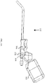
- FIG. 2A shows an exemplary wireless tool 102.
- the wireless tool 102 may be a wireless medical tool.
- the wireless tool 102 may obtain power by one or more batteries via a battery pack or battery holder 202.
- Current wireless tools provide short-range radio technology to enable wireless communications. These technologies enable the wireless transmission and receiving of signals; however, they cause significant power consumption by the tool.
- the present system aims to conserve and manage power, by limiting power consumption from wireless communications by switching to a low power mode during non-use of the wireless tool 102. The low power mode enables reduction of battery consumption to preserve and extend the duration of usage of the tool.
- the wireless tool 102 can comprise a detection mechanism comprising an inductor 204 and resistors 206, 208 for transmitting signals including voltage, to the processor 108, as shown in FIG. 1 .
- the wireless tool 102 receives electromagnetic fields with specific frequency signals ("magnetic location frequencies") for purposes of magnetic navigation.
- the frequencies may range from 17 kilohertz (kHz) to 19.8 kHz. In other embodiments, the frequencies may be higher or lower in value.
- the inductor 204 receives the signals and is tuned with a capacitor to the specific frequency of the location. The inductor 204 is passive and thus does not consume power.
- the coil When the signal received by the inductor 204 is not at magnetic location frequencies, the coil is discharged through resistor 206, and the voltage on resistor 208 is very low. This voltage signal is sent to the processor 108, as shown in FIG. 1 , and the processor 108 analyzes the signal and maintains the wireless tool 102 in a hibernation mode.
- the voltage on resistor 208 increases and exceeds the frequency threshold.
- This voltage signal is sent to the processor 108, as shown in FIG. 1 , which causes the wireless tool 102 to be enabled or activated to an active power mode.
- the processor 108 communicates with the wireless tool 102 via wireless frequency (WiFi) and the processor 108 calculates the location of the wireless tool 102 and its orientation in space.
- WiFi wireless frequency
- the hibernation mode may include not transmitting or receiving wireless communications between the wireless tool 102 and the processor 108, as well as an overall reduced power during periods of non-use of the wireless tool 102. Other reduced power management schemes may be employed.
- wireless communication can be limited to location detection only.
- the wireless tool 102 may generate either a visible or audible indication to indicate sufficient battery power is available.
- a visible indication may include an illuminating light emitting diode (LED) and/or an indicator on the monitor 112, while an audible indication may include a periodically sounding audible tone.
- the audible indication may be produced through speakers (not shown) in the console 110.
- a visible or audible indication may also be used to indicate when the battery power falls below a certain threshold.
- FIG. 2B is an electrical diagram of an embodiment of the power management system.
- the inductor 204 receives the frequency signals emitted by the location pad 104 and is tuned with a capacitor 210 to the specific frequency of the location.
- the signal received by the inductor 204 is not at magnetic location frequencies, the coil is discharged through resistor 206, and the voltage on resistor 208 is very low. The wireless tool 102 is thus maintained in a hibernation mode.
- the wireless tool 102 When the wireless tool 102 is moved to a location where it will be used, e.g., inductor 204 matches the specific frequency of the capacitor 210 of the location, the voltage on resistor 208 increases and exceeds the frequency threshold, which causes the wireless tool 102 to be enabled or activated to an active power mode. Otherwise, while the voltage remains low, the wireless tool 102 remains in hibernation mode. Maintaining the wireless tool 102 in a hibernation mode during non-use and activating or enabling the wireless tool 102 when it is moved to a location where it will be used thus conserves battery power and prolongs the life of the wireless tool 102. This configuration may also allow a smaller battery to be used in the wireless tool 102, since less battery power is required to maintain the wireless tool during a procedure.
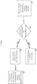
- FIG. 3 is a flow diagram of an embodiment of the inventive method for switching on a wireless tool when location frequencies are detected. This procedure is typically performed during a medical procedure.
- the wireless tool 102 receives the magnetic location frequencies emitted by the location pad 104 via the inductor 204, so that the coil is discharged through a first resistor 206 and affects the voltage of the second resistor 208.
- step S5 the acquired mixed signal from step S1 is processed by the processor 108 to determine the frequencies emitted by each respective coil.
- the processor 108 applies an algorithm to detect the signal amplitude above a certain frequency threshold. Every reception mode provides the possibility of noise or other unwanted input signals besides the desired signals, so different detection approaches may be used.
- the algorithm applied by the processor 108, to determine the location and orientation of the wireless tool 102 in three-dimensional space is the Goertzel algorithm.
- the processor 108 communicates with the tool via WiFi.
- DFT discrete Fourier transforms
- FFT Fast Fourier Transformation
- processors include, by way of example, a general purpose processor, a special purpose processor, a conventional processor, a digital signal processor (DSP), a plurality of microprocessors, one or more microprocessors in association with a DSP core, a controller, a microcontroller, Application Specific Integrated Circuits (ASICs), Field Programmable Gate Arrays (FPGAs) circuits, any other type of integrated circuit (IC), and/or a state machine.
- DSP digital signal processor
- ASICs Application Specific Integrated Circuits
- FPGAs Field Programmable Gate Arrays
- Such processors can be manufactured by configuring a manufacturing process using the results of processed hardware description language (HDL) instructions and other intermediary data including netlists (such instructions capable of being stored on a computer readable media).
- HDL hardware description language
- non-transitory computer-readable storage mediums include a ROM, a random access memory (RAM), a register, cache memory, semiconductor memory devices, magnetic media such as internal hard disks and removable disks, magneto-optical media, and optical media such as CD-ROM disks, and digital versatile disks (DVDs).
Landscapes
- Engineering & Computer Science (AREA)
- Signal Processing (AREA)
- Computer Networks & Wireless Communication (AREA)
- Health & Medical Sciences (AREA)
- General Physics & Mathematics (AREA)
- Physics & Mathematics (AREA)
- Surgery (AREA)
- Life Sciences & Earth Sciences (AREA)
- Business, Economics & Management (AREA)
- Power Engineering (AREA)
- Emergency Management (AREA)
- Biomedical Technology (AREA)
- Public Health (AREA)
- Veterinary Medicine (AREA)
- General Health & Medical Sciences (AREA)
- Animal Behavior & Ethology (AREA)
- Molecular Biology (AREA)
- Medical Informatics (AREA)
- Heart & Thoracic Surgery (AREA)
- Robotics (AREA)
- Nuclear Medicine, Radiotherapy & Molecular Imaging (AREA)
- Automation & Control Theory (AREA)
- Charge And Discharge Circuits For Batteries Or The Like (AREA)
- Direct Current Feeding And Distribution (AREA)
Abstract
Description
- The present invention relates generally to managing power for wireless tools, and more specifically to extending battery life and power of a battery-operated wireless tool by switching the tools on or off based on location detection.
- Non-fixed medical tools are used for a variety of critical health procedures and require a highly reliable power management system to prevent power failure. Medical systems traditionally transmit signals to connect with non-fixed medical tools and to receive a constant and reliable power source to the non-fixed tool over a fixed wire or cable. These non-fixed wired systems and tools employed a fixed wire connection to receive a constant reliable source of power. The advancement of short-range radio technology now affords medical tool manufacturers the ability to create non-fixed tools without the need for a fixed physical cable. For example, non-fixed tools meeting or complying with the Institute of Electrical and Electronics Engineers (IEEE) 802.11g, IrDA (infrared data), and Ericsson Bluetooth™ specifications provide short-range radio technology to enable wireless communications.
- Current non-fixed wireless tools, however, do not include a fixed continuous reliable power source. Instead, the tools rely on a portable battery power source, typically with a finite life of about three to four hours, for operation when active. Thus, if the battery is not charged or properly recharged, it could fail (i.e. run out of charge) during a procedure. Due to the critical health support requirements for these medical tools and the potential consequences of a power failure in such equipment, the tools therefore require a highly reliable battery power management system.
- These battery-operated wireless tools, when used under normal operation, are exposed to functional issues. One example of a functional issue is that manufacturers of medical tools seek to create tools that are as small and light as possible for use in specific medical procedures, especially in ENT procedures. On the other hand, the battery-operated wireless tool must maintain power as long as possible, which requires the application of a larger-sized battery.
- Another example of a functional issue is providing wireless location indication at all times to the user. During a surgical or medical procedure, a physician may use numerous wireless tools, but will not use all of those tools for the entirety of the procedure. Instead, a physician typically uses a battery-operated wireless tool for a specific period of time and then puts it aside and uses other wireless tools for other portions of the procedure, and may use the battery-operated wireless tool again at a later period. Thus, battery-operated wireless tools that are not in use by the physician for a period of time during the procedure are still on and constantly providing an indication of the tool's location and/or status. This poses a particular challenge for power management, since the battery of the battery-operated wireless tool has a finite life and power is constantly decreasing as the tool is on and providing the tool's location, even during non-use. Moreover, physicians are not interested in location indication of wireless tools that are set aside during a procedure; instead, physicians prefer location indication of the tool that they are currently using.
- Thus, it would be advantageous to offer a system that extends the battery life of a battery-operated wireless tool by switching on the wireless tool when location frequencies are detected, and subsequently invoking a low-powered hibernation or other power saving mode when location frequencies are not detected to ensure proper and extended wireless tool operation during procedures.
- A method and system for managing power of a wireless tool is provided. The method comprises acquiring a mixed electromagnetic frequency signal emitted by a location pad for electromagnetic navigation purposes and determining a voltage based on the signal; setting the wireless tool to a hibernation mode when the voltage is below the predetermined amount because the tool is far away from navigational space and thus does not need to be navigated; and setting the wireless tool to an active mode and applying an algorithm to calculate the location and orientation of the wireless tool when the voltage is above the predetermined amount. The system comprises a location pad comprising at least one field generator, a wireless tool configured to receive a mixed electromagnetic frequency signal, and a processor configured to analyze a mixed signal and determine a voltage, set the wireless tool to a hibernation mode when the voltage is below a predetermined amount, and set the wireless tool to an active mode and apply an algorithm to calculate the location and orientation of the wireless tool when the voltage is above the predetermined amount.
- The present invention is illustrated by way of example, and not by way of limitation, in the figures of the accompanying drawings in which:
-
FIG. 1 is a schematic diagram of a power management system for a wireless tool in accordance with an embodiment of the present invention. -
FIG. 2A is an exemplary wireless tool of the power management system. -
FIG. 2B is an electrical diagram of an embodiment of the power management system. -
FIG. 3 is a flow diagram of a method for activating a power mode and/or a hibernation mode of a wireless tool in accordance with an embodiment of the present invention. - A system and method for switching on a wireless tool and switching the wireless tool to a low power or hibernation mode when location frequencies are detected is presented.
-
FIG. 1 illustrates a schematic diagram of thepower management system 100 for a wireless tool in accordance with an embodiment of the present invention. Thepower management system 100 includes awireless tool 102, a location pad comprising at least onefield generator 104, aprocessor 108, aconsole 110 and a display ormonitor 112. Thewireless tool 102 can be a wireless medical tool. Themonitor 112 can be attached to theconsole 110 or can be mounted separately from theconsole 110. - As shown in
FIG. 1 , anindividual 114, such as a physician, operates thesystem 100 to perform a medical procedure on apatient 116. Thephysician 114 uses thewireless tool 102 when performing a portion of the medical procedure. During other portions of the medical procedure, thewireless tool 102 is not used. - In one embodiment, the
location pad 104 may comprise one field generator. In another embodiment, thelocation pad 104 may comprise multiple field generators. Each field generator may include multiple coils (not shown) that, during a medical procedure, emit electromagnetic fields, each of its own frequency, and one or more sensors (not shown) that detect the frequencies emitted. The system uses the electromagnetic fields generated by thefield generators 104 and detected by the sensors to, among other things, calculate and determine the location of a tool in three-dimensional space. When thetool 102 is not in use, the system may detect an "out of range" location of thetool 102, e.g., a location that is not in accordance with use of thetool 102, and switch thetool 102 to a hibernation mode because the tool is far away from navigational space and thus does not need to be navigated. The system calculates whether signal amplitude from thetool 102 does or does not exceed a certain frequency threshold. If the frequency threshold is exceeded, thetool 102 is in position to be used. If thetool 102 had been in hibernation mode, and it now exceeds the threshold, thetool 102 is switched on or activated. Throughout the medical procedure, when the frequency threshold is exceeded, thewireless tool 102 remains active or in use. Otherwise, when the frequency threshold is less than a predetermined threshold, thewireless tool 102 is switched to and maintained in hibernation mode. -
FIG. 2A shows an exemplarywireless tool 102. In one embodiment, thewireless tool 102 may be a wireless medical tool. Thewireless tool 102 may obtain power by one or more batteries via a battery pack orbattery holder 202. Current wireless tools provide short-range radio technology to enable wireless communications. These technologies enable the wireless transmission and receiving of signals; however, they cause significant power consumption by the tool. The present system aims to conserve and manage power, by limiting power consumption from wireless communications by switching to a low power mode during non-use of thewireless tool 102. The low power mode enables reduction of battery consumption to preserve and extend the duration of usage of the tool. - The
wireless tool 102 can comprise a detection mechanism comprising aninductor 204 andresistors processor 108, as shown inFIG. 1 . During a medical procedure, thewireless tool 102 receives electromagnetic fields with specific frequency signals ("magnetic location frequencies") for purposes of magnetic navigation. In the present embodiment, the frequencies may range from 17 kilohertz (kHz) to 19.8 kHz. In other embodiments, the frequencies may be higher or lower in value. Theinductor 204 receives the signals and is tuned with a capacitor to the specific frequency of the location. Theinductor 204 is passive and thus does not consume power. When the signal received by theinductor 204 is not at magnetic location frequencies, the coil is discharged throughresistor 206, and the voltage onresistor 208 is very low. This voltage signal is sent to theprocessor 108, as shown inFIG. 1 , and theprocessor 108 analyzes the signal and maintains thewireless tool 102 in a hibernation mode. - When the
wireless tool 102 is moved to a location where it will be used, the voltage onresistor 208 increases and exceeds the frequency threshold. This voltage signal is sent to theprocessor 108, as shown inFIG. 1 , which causes thewireless tool 102 to be enabled or activated to an active power mode. When thewireless tool 102 is enabled, theprocessor 108 communicates with thewireless tool 102 via wireless frequency (WiFi) and theprocessor 108 calculates the location of thewireless tool 102 and its orientation in space. - The hibernation mode may include not transmitting or receiving wireless communications between the
wireless tool 102 and theprocessor 108, as well as an overall reduced power during periods of non-use of thewireless tool 102. Other reduced power management schemes may be employed. In hibernation mode, wireless communication can be limited to location detection only. - Furthermore, the
wireless tool 102 may generate either a visible or audible indication to indicate sufficient battery power is available. A visible indication may include an illuminating light emitting diode (LED) and/or an indicator on themonitor 112, while an audible indication may include a periodically sounding audible tone. The audible indication may be produced through speakers (not shown) in theconsole 110. A visible or audible indication may also be used to indicate when the battery power falls below a certain threshold. -
FIG. 2B is an electrical diagram of an embodiment of the power management system. In the present embodiment, theinductor 204 receives the frequency signals emitted by thelocation pad 104 and is tuned with acapacitor 210 to the specific frequency of the location. When the signal received by theinductor 204 is not at magnetic location frequencies, the coil is discharged throughresistor 206, and the voltage onresistor 208 is very low. Thewireless tool 102 is thus maintained in a hibernation mode. - When the
wireless tool 102 is moved to a location where it will be used, e.g.,inductor 204 matches the specific frequency of thecapacitor 210 of the location, the voltage onresistor 208 increases and exceeds the frequency threshold, which causes thewireless tool 102 to be enabled or activated to an active power mode. Otherwise, while the voltage remains low, thewireless tool 102 remains in hibernation mode. Maintaining thewireless tool 102 in a hibernation mode during non-use and activating or enabling thewireless tool 102 when it is moved to a location where it will be used thus conserves battery power and prolongs the life of thewireless tool 102. This configuration may also allow a smaller battery to be used in thewireless tool 102, since less battery power is required to maintain the wireless tool during a procedure. -
FIG. 3 is a flow diagram of an embodiment of the inventive method for switching on a wireless tool when location frequencies are detected. This procedure is typically performed during a medical procedure. In step S1, thewireless tool 102 receives the magnetic location frequencies emitted by thelocation pad 104 via theinductor 204, so that the coil is discharged through afirst resistor 206 and affects the voltage of thesecond resistor 208. In step S2, the voltage is compared to a predetermined amount. If this voltage is below the predetermined amount (S2=YES), then the system recognizes that the tool is inactive. In step S3, the tool is switched to or maintained in hibernation mode and the system continues to monitor the tool by returning to step S1. If the voltage ofresistor 208 is not less than the predetermined amount (S2=NO), then in step S4, theprocessor 108 activates thewireless tool 102 to an active power mode. - In step S5, the acquired mixed signal from step S1 is processed by the
processor 108 to determine the frequencies emitted by each respective coil. In one embodiment, in step S5 theprocessor 108 applies an algorithm to detect the signal amplitude above a certain frequency threshold. Every reception mode provides the possibility of noise or other unwanted input signals besides the desired signals, so different detection approaches may be used. In one embodiment, the algorithm applied by theprocessor 108, to determine the location and orientation of thewireless tool 102 in three-dimensional space, is the Goertzel algorithm. In addition, theprocessor 108 communicates with the tool via WiFi. - One problem with discrete Fourier transforms (DFT) and fast Fourier transforms is that it is not very efficient to estimate the Fourier transform coefficients at a small number of frequencies although it is very efficient to estimate the coefficients at larger number of frequencies. This problem can be overcome by evaluating samples at the actual dual-tone multi-frequency (DTMF) frequencies using a non-uniform DFT. One example of a non-uniform DFT is the Goertzel algorithm. In contrast to Fast Fourier Transformation (FFT), the Goertzel algorithm can always be employed if a known, discrete frequency is to be analyzed. This is typically the case in the detection mechanism of the present invention.
- It should be understood that many variations are possible based on the disclosure herein. Although features and elements are described above in particular combinations, each feature or element can be used alone without the other features and elements or in various combinations with or without other features and elements.
- The methods provided include implementation in a general purpose computer, a processor, or a processor core. Suitable processors include, by way of example, a general purpose processor, a special purpose processor, a conventional processor, a digital signal processor (DSP), a plurality of microprocessors, one or more microprocessors in association with a DSP core, a controller, a microcontroller, Application Specific Integrated Circuits (ASICs), Field Programmable Gate Arrays (FPGAs) circuits, any other type of integrated circuit (IC), and/or a state machine. Such processors can be manufactured by configuring a manufacturing process using the results of processed hardware description language (HDL) instructions and other intermediary data including netlists (such instructions capable of being stored on a computer readable media).
- The methods or flow charts provided herein can be implemented in a computer program, software, or firmware incorporated in a non-transitory computer-readable storage medium for execution by a general purpose computer or a processor. Examples of non-transitory computer-readable storage mediums include a ROM, a random access memory (RAM), a register, cache memory, semiconductor memory devices, magnetic media such as internal hard disks and removable disks, magneto-optical media, and optical media such as CD-ROM disks, and digital versatile disks (DVDs).
Claims (14)
- A method for managing power of a wireless tool, comprising:acquiring a mixed signal and determining a voltage ;when the voltage is below a predetermined amount, setting the wireless tool to a hibernation mode; andwhen the voltage is above the predetermined amount, setting the wireless tool to an active mode and applying an algorithm to calculate the location and orientation of the wireless tool.
- The method according to claim 1, further comprising:
using a resistor to determine the voltage. - The method according to claim 1, wherein the algorithm is the Goertzel algorithm.
- A system for managing power of a wireless tool, comprising:a wireless tool; anda processor configured to:analyze a mixed signal and determine a voltage;when the voltage is below a predetermined amount, set the wireless tool to a hibernation mode; andwhen the voltage is above the predetermined amount, set the wireless tool to an active mode and applying an algorithm to calculate the location and orientation of the wireless tool.
- The system according to claim 4, further comprising a monitor displaying an indicator indicating the hibernation mode is set.
- The system according to claim 4, wherein the wireless tool further comprises:at least one inductor,at least one capacitor, andat least one resistor.
- The system according to claim 6, wherein the inductor is tuned with the capacitor to a specific frequency of the location of the wireless tool.
- The system according to claim 7, wherein the inductor is configured to receive frequency signals emitted by a location pad.
- The system according to claim 6, wherein the resistor is configured to transmit voltage signals.
- The system according to claim 4, wherein the system further comprises an audible indication of battery power of the wireless tool.
- The system according to claim 4, wherein the system further comprises a visible indication of battery power of the wireless tool.
- The method according to claim 1 or the system according to claim 4, wherein the hibernation mode includes signal detection only.
- The method according to claim 1 or the system according to claim 4, wherein the active mode enables wireless communication transmittance.
- A computer software product, including a non-transitory computer readable storage medium in which computer program instructions are stored, which instructions, when executed by a computer, cause the computer to perform the steps of:acquiring a mixed signal emitted by a wireless tool and determining a voltage;when the voltage is below a predetermined amount, setting the wireless tool to a hibernation mode; andwhen the voltage is above the predetermined amount, setting the wireless tool to an active mode and applying an algorithm to calculate the location and orientation of the wireless tool.
Applications Claiming Priority (1)
| Application Number | Priority Date | Filing Date | Title |
|---|---|---|---|
| US15/479,467 US10244481B2 (en) | 2017-04-05 | 2017-04-05 | System and method for switching on wireless tool only when the location frequencies are detected |
Publications (2)
| Publication Number | Publication Date |
|---|---|
| EP3386245A1 true EP3386245A1 (en) | 2018-10-10 |
| EP3386245B1 EP3386245B1 (en) | 2019-09-04 |
Family
ID=62044466
Family Applications (1)
| Application Number | Title | Priority Date | Filing Date |
|---|---|---|---|
| EP18165645.5A Active EP3386245B1 (en) | 2017-04-05 | 2018-04-04 | System and method for switching on a wireless tool when location frequencies are detected |
Country Status (8)
| Country | Link |
|---|---|
| US (1) | US10244481B2 (en) |
| EP (1) | EP3386245B1 (en) |
| JP (1) | JP7184530B2 (en) |
| CN (1) | CN108693803B (en) |
| AU (1) | AU2018202206A1 (en) |
| CA (1) | CA3000349A1 (en) |
| ES (1) | ES2754675T3 (en) |
| IL (1) | IL258428B (en) |
Families Citing this family (15)
| Publication number | Priority date | Publication date | Assignee | Title |
|---|---|---|---|---|
| FR3010628B1 (en) | 2013-09-18 | 2015-10-16 | Medicrea International | METHOD FOR REALIZING THE IDEAL CURVATURE OF A ROD OF A VERTEBRAL OSTEOSYNTHESIS EQUIPMENT FOR STRENGTHENING THE VERTEBRAL COLUMN OF A PATIENT |
| FR3012030B1 (en) | 2013-10-18 | 2015-12-25 | Medicrea International | METHOD FOR REALIZING THE IDEAL CURVATURE OF A ROD OF A VERTEBRAL OSTEOSYNTHESIS EQUIPMENT FOR STRENGTHENING THE VERTEBRAL COLUMN OF A PATIENT |
| AU2016349705B2 (en) | 2015-11-04 | 2021-07-29 | Medicrea International | Methods and Apparatus for spinal reconstructive surgery and measuring spinal length and intervertebral spacing, tension and rotation |
| WO2018109556A1 (en) | 2016-12-12 | 2018-06-21 | Medicrea International | Systems and methods for patient-specific spinal implants |
| JP7165668B2 (en) | 2017-04-21 | 2022-11-04 | メディクレア インターナショナル | System for developing one or more patient-specific spinal implants |
| US10918422B2 (en) | 2017-12-01 | 2021-02-16 | Medicrea International | Method and apparatus for inhibiting proximal junctional failure |
| US12564447B2 (en) | 2019-04-02 | 2026-03-03 | Medicrea International | Systems, methods, and devices for developing patient-specific spinal implants, treatments, operations, and/or procedures |
| US11877801B2 (en) | 2019-04-02 | 2024-01-23 | Medicrea International | Systems, methods, and devices for developing patient-specific spinal implants, treatments, operations, and/or procedures |
| US11925417B2 (en) | 2019-04-02 | 2024-03-12 | Medicrea International | Systems, methods, and devices for developing patient-specific spinal implants, treatments, operations, and/or procedures |
| US11944385B2 (en) | 2019-04-02 | 2024-04-02 | Medicrea International | Systems and methods for medical image analysis |
| US11919141B2 (en) | 2019-08-27 | 2024-03-05 | Ingersoll-Rand Industrial U.S., Inc. | Tool with wireless switch |
| US11931878B2 (en) | 2019-08-27 | 2024-03-19 | Ingersoll-Rand Industrial U.S., Inc. | Quick change auxiliary handle for power tool |
| US11769251B2 (en) | 2019-12-26 | 2023-09-26 | Medicrea International | Systems and methods for medical image analysis |
| CN114052809B (en) * | 2020-08-04 | 2022-12-23 | 苏州英途康医疗科技有限公司 | Electric stapler and its handle low power consumption control method, device and storage medium |
| US12318144B2 (en) | 2021-06-23 | 2025-06-03 | Medicrea International SA | Systems and methods for planning a patient-specific spinal correction |
Citations (4)
| Publication number | Priority date | Publication date | Assignee | Title |
|---|---|---|---|---|
| US20150374378A1 (en) * | 2007-01-10 | 2015-12-31 | Ethicon Endo-Surgery, Inc. | Surgical instrument with wireless communication between control unit and remote sensor |
| WO2016032875A1 (en) * | 2014-08-28 | 2016-03-03 | DePuy Synthes Products, Inc. | Systems and methods for intraoperatively measuring anatomical orientation |
| US20170003713A1 (en) * | 2015-06-30 | 2017-01-05 | Intel IP Corporation | Location-based power saving solution for wireless docking products |
| EP3135193A1 (en) * | 2004-03-05 | 2017-03-01 | Biosense Webster, Inc. | Position sensing system for orthopaedic applications |
Family Cites Families (23)
| Publication number | Priority date | Publication date | Assignee | Title |
|---|---|---|---|---|
| US5721662A (en) * | 1992-07-29 | 1998-02-24 | Act Communications, Inc. | Floating ground isolator for a communications cable locating system |
| US6147480A (en) * | 1997-10-23 | 2000-11-14 | Biosense, Inc. | Detection of metal disturbance |
| US6219540B1 (en) | 1998-11-23 | 2001-04-17 | Motorola, Inc. | Communication device providing out-of-range battery saving and method therefor |
| US6233476B1 (en) * | 1999-05-18 | 2001-05-15 | Mediguide Ltd. | Medical positioning system |
| US6586911B1 (en) * | 2002-02-06 | 2003-07-01 | National Semiconductor Corporation | Sleep mode power management |
| JP3878625B2 (en) * | 2003-06-20 | 2007-02-07 | 松下電器産業株式会社 | Amplitude adjustment circuit, motor drive control device, amplitude adjustment method, and motor drive control method |
| US7064510B2 (en) * | 2004-11-10 | 2006-06-20 | Andigilog, Inc. | Controller arrangement with automatic power down |
| US20060241397A1 (en) * | 2005-02-22 | 2006-10-26 | Assaf Govari | Reference pad for position sensing |
| KR101397210B1 (en) * | 2005-06-28 | 2014-05-21 | 스트리커 코포레이션 | Control assembly for a motorized surgical tool that contains a sensor that monitors the state of the motor rotor |
| US20070146351A1 (en) * | 2005-12-12 | 2007-06-28 | Yuji Katsurahira | Position input device and computer system |
| US20070195784A1 (en) | 2006-02-22 | 2007-08-23 | Motorola, Inc. | Power saving scheme for nodes that are out of range of a network |
| JP4946646B2 (en) * | 2006-07-10 | 2012-06-06 | 日産自動車株式会社 | Communication network system and wakeup method for unwakened node |
| US20080058883A1 (en) * | 2006-08-29 | 2008-03-06 | Motorola, Inc. | Method and system to control early battery end of life events on multi-transceiver systems |
| KR101463471B1 (en) * | 2007-06-05 | 2014-11-19 | 삼성전자주식회사 | Display apparatus to notify status of a external device |
| CA2692408A1 (en) * | 2007-07-13 | 2009-01-22 | Boston Scientific Scimed, Inc. | Hybrid and portable power supplies for electrolytically detaching implantable medical devices |
| US20090163226A1 (en) * | 2007-12-20 | 2009-06-25 | Burges Karkaria | Device, system, and method of power saving using location sensing modules |
| US8351892B2 (en) | 2009-05-26 | 2013-01-08 | Qualcomm Incorporated | Network detection device power conservation |
| US8452353B2 (en) | 2010-02-24 | 2013-05-28 | Hewlett-Packard Development Company, L.P. | Apparatus and methods for providing intelligent battery management |
| US9219378B2 (en) * | 2010-11-01 | 2015-12-22 | Qualcomm Incorporated | Wireless charging of devices |
| US9696429B2 (en) * | 2010-12-28 | 2017-07-04 | Fedex Corporate Services, Inc. | Power management in wireless tracking device operating with restricted power source |
| US9148201B2 (en) * | 2011-02-11 | 2015-09-29 | Qualcomm Incorporated | Systems and methods for calibration of a wireless power transmitter |
| US9118357B2 (en) * | 2011-02-17 | 2015-08-25 | Qualcomm Incorporated | Systems and methods for controlling output power of a wireless power transmitter |
| US9498231B2 (en) * | 2011-06-27 | 2016-11-22 | Board Of Regents Of The University Of Nebraska | On-board tool tracking system and methods of computer assisted surgery |
-
2017
- 2017-04-05 US US15/479,467 patent/US10244481B2/en active Active
-
2018
- 2018-03-28 IL IL258428A patent/IL258428B/en active IP Right Grant
- 2018-03-28 AU AU2018202206A patent/AU2018202206A1/en not_active Abandoned
- 2018-04-04 CA CA3000349A patent/CA3000349A1/en not_active Abandoned
- 2018-04-04 JP JP2018072163A patent/JP7184530B2/en active Active
- 2018-04-04 CN CN201810304749.3A patent/CN108693803B/en active Active
- 2018-04-04 EP EP18165645.5A patent/EP3386245B1/en active Active
- 2018-04-04 ES ES18165645T patent/ES2754675T3/en active Active
Patent Citations (4)
| Publication number | Priority date | Publication date | Assignee | Title |
|---|---|---|---|---|
| EP3135193A1 (en) * | 2004-03-05 | 2017-03-01 | Biosense Webster, Inc. | Position sensing system for orthopaedic applications |
| US20150374378A1 (en) * | 2007-01-10 | 2015-12-31 | Ethicon Endo-Surgery, Inc. | Surgical instrument with wireless communication between control unit and remote sensor |
| WO2016032875A1 (en) * | 2014-08-28 | 2016-03-03 | DePuy Synthes Products, Inc. | Systems and methods for intraoperatively measuring anatomical orientation |
| US20170003713A1 (en) * | 2015-06-30 | 2017-01-05 | Intel IP Corporation | Location-based power saving solution for wireless docking products |
Also Published As
| Publication number | Publication date |
|---|---|
| IL258428A (en) | 2018-06-28 |
| CN108693803B (en) | 2023-09-01 |
| JP7184530B2 (en) | 2022-12-06 |
| US20180295584A1 (en) | 2018-10-11 |
| US10244481B2 (en) | 2019-03-26 |
| CA3000349A1 (en) | 2018-10-05 |
| AU2018202206A1 (en) | 2018-10-25 |
| EP3386245B1 (en) | 2019-09-04 |
| IL258428B (en) | 2020-11-30 |
| JP2018183041A (en) | 2018-11-15 |
| ES2754675T3 (en) | 2020-04-20 |
| CN108693803A (en) | 2018-10-23 |
Similar Documents
| Publication | Publication Date | Title |
|---|---|---|
| US10244481B2 (en) | System and method for switching on wireless tool only when the location frequencies are detected | |
| AU2018202872A1 (en) | Wireless tool with accelerometer for selective power saving | |
| JP2018183041A5 (en) | Systems and methods for switching on wireless tools when location frequencies are detected | |
| JP6761416B2 (en) | Automatic configuration of low magnetic field magnetic resonance imaging system | |
| US9929605B2 (en) | Wireless power transfer device with foreign object detection, system, and method for performing the same | |
| KR102765661B1 (en) | Wireless power systems with shared inductive-loss scaling factors | |
| US8508378B2 (en) | System and method for extending the battery life in inventory control devices | |
| US9610065B2 (en) | Probe control method and apparatus | |
| US20150169915A1 (en) | Active rfid tag with integrated electrical pass-through connection | |
| US10241164B2 (en) | Status acquisition of a RF coil on or in a magnetic resonance device | |
| US11586870B2 (en) | Usage, condition and location tag and system | |
| JP6708662B2 (en) | Method and apparatus for performing presence and usage pattern detection in wireless charging applications | |
| US20260051767A1 (en) | Wireless power supply system, system, and transmitter | |
| EP3184042A1 (en) | Electronic device and computer-readable recording medium | |
| US9985475B2 (en) | Power supply apparatus and method | |
| US9338742B2 (en) | Method and apparatus for reducing power consumption of receiver | |
| EP4537658A1 (en) | Animal monitoring device | |
| US20230253832A1 (en) | Electronic device |
Legal Events
| Date | Code | Title | Description |
|---|---|---|---|
| PUAI | Public reference made under article 153(3) epc to a published international application that has entered the european phase |
Free format text: ORIGINAL CODE: 0009012 |
|
| STAA | Information on the status of an ep patent application or granted ep patent |
Free format text: STATUS: THE APPLICATION HAS BEEN PUBLISHED |
|
| AK | Designated contracting states |
Kind code of ref document: A1 Designated state(s): AL AT BE BG CH CY CZ DE DK EE ES FI FR GB GR HR HU IE IS IT LI LT LU LV MC MK MT NL NO PL PT RO RS SE SI SK SM TR |
|
| AX | Request for extension of the european patent |
Extension state: BA ME |
|
| STAA | Information on the status of an ep patent application or granted ep patent |
Free format text: STATUS: REQUEST FOR EXAMINATION WAS MADE |
|
| 17P | Request for examination filed |
Effective date: 20190402 |
|
| RBV | Designated contracting states (corrected) |
Designated state(s): AL AT BE BG CH CY CZ DE DK EE ES FI FR GB GR HR HU IE IS IT LI LT LU LV MC MK MT NL NO PL PT RO RS SE SI SK SM TR |
|
| GRAP | Despatch of communication of intention to grant a patent |
Free format text: ORIGINAL CODE: EPIDOSNIGR1 |
|
| STAA | Information on the status of an ep patent application or granted ep patent |
Free format text: STATUS: GRANT OF PATENT IS INTENDED |
|
| INTG | Intention to grant announced |
Effective date: 20190603 |
|
| GRAS | Grant fee paid |
Free format text: ORIGINAL CODE: EPIDOSNIGR3 |
|
| GRAA | (expected) grant |
Free format text: ORIGINAL CODE: 0009210 |
|
| STAA | Information on the status of an ep patent application or granted ep patent |
Free format text: STATUS: THE PATENT HAS BEEN GRANTED |
|
| AK | Designated contracting states |
Kind code of ref document: B1 Designated state(s): AL AT BE BG CH CY CZ DE DK EE ES FI FR GB GR HR HU IE IS IT LI LT LU LV MC MK MT NL NO PL PT RO RS SE SI SK SM TR |
|
| REG | Reference to a national code |
Ref country code: GB Ref legal event code: FG4D |
|
| REG | Reference to a national code |
Ref country code: CH Ref legal event code: EP Ref country code: CH Ref legal event code: NV Representative=s name: E. BLUM AND CO. AG PATENT- UND MARKENANWAELTE , CH |
|
| REG | Reference to a national code |
Ref country code: AT Ref legal event code: REF Ref document number: 1177179 Country of ref document: AT Kind code of ref document: T Effective date: 20190915 |
|
| REG | Reference to a national code |
Ref country code: DE Ref legal event code: R096 Ref document number: 602018000555 Country of ref document: DE |
|
| REG | Reference to a national code |
Ref country code: IE Ref legal event code: FG4D |
|
| REG | Reference to a national code |
Ref country code: NL Ref legal event code: FP |
|
| REG | Reference to a national code |
Ref country code: LT Ref legal event code: MG4D |
|
| PG25 | Lapsed in a contracting state [announced via postgrant information from national office to epo] |
Ref country code: FI Free format text: LAPSE BECAUSE OF FAILURE TO SUBMIT A TRANSLATION OF THE DESCRIPTION OR TO PAY THE FEE WITHIN THE PRESCRIBED TIME-LIMIT Effective date: 20190904 Ref country code: SE Free format text: LAPSE BECAUSE OF FAILURE TO SUBMIT A TRANSLATION OF THE DESCRIPTION OR TO PAY THE FEE WITHIN THE PRESCRIBED TIME-LIMIT Effective date: 20190904 Ref country code: LT Free format text: LAPSE BECAUSE OF FAILURE TO SUBMIT A TRANSLATION OF THE DESCRIPTION OR TO PAY THE FEE WITHIN THE PRESCRIBED TIME-LIMIT Effective date: 20190904 Ref country code: HR Free format text: LAPSE BECAUSE OF FAILURE TO SUBMIT A TRANSLATION OF THE DESCRIPTION OR TO PAY THE FEE WITHIN THE PRESCRIBED TIME-LIMIT Effective date: 20190904 Ref country code: NO Free format text: LAPSE BECAUSE OF FAILURE TO SUBMIT A TRANSLATION OF THE DESCRIPTION OR TO PAY THE FEE WITHIN THE PRESCRIBED TIME-LIMIT Effective date: 20191204 Ref country code: BG Free format text: LAPSE BECAUSE OF FAILURE TO SUBMIT A TRANSLATION OF THE DESCRIPTION OR TO PAY THE FEE WITHIN THE PRESCRIBED TIME-LIMIT Effective date: 20191204 |
|
| PG25 | Lapsed in a contracting state [announced via postgrant information from national office to epo] |
Ref country code: RS Free format text: LAPSE BECAUSE OF FAILURE TO SUBMIT A TRANSLATION OF THE DESCRIPTION OR TO PAY THE FEE WITHIN THE PRESCRIBED TIME-LIMIT Effective date: 20190904 Ref country code: LV Free format text: LAPSE BECAUSE OF FAILURE TO SUBMIT A TRANSLATION OF THE DESCRIPTION OR TO PAY THE FEE WITHIN THE PRESCRIBED TIME-LIMIT Effective date: 20190904 Ref country code: AL Free format text: LAPSE BECAUSE OF FAILURE TO SUBMIT A TRANSLATION OF THE DESCRIPTION OR TO PAY THE FEE WITHIN THE PRESCRIBED TIME-LIMIT Effective date: 20190904 Ref country code: GR Free format text: LAPSE BECAUSE OF FAILURE TO SUBMIT A TRANSLATION OF THE DESCRIPTION OR TO PAY THE FEE WITHIN THE PRESCRIBED TIME-LIMIT Effective date: 20191205 |
|
| REG | Reference to a national code |
Ref country code: AT Ref legal event code: MK05 Ref document number: 1177179 Country of ref document: AT Kind code of ref document: T Effective date: 20190904 |
|
| REG | Reference to a national code |
Ref country code: ES Ref legal event code: FG2A Ref document number: 2754675 Country of ref document: ES Kind code of ref document: T3 Effective date: 20200420 |
|
| PG25 | Lapsed in a contracting state [announced via postgrant information from national office to epo] |
Ref country code: RO Free format text: LAPSE BECAUSE OF FAILURE TO SUBMIT A TRANSLATION OF THE DESCRIPTION OR TO PAY THE FEE WITHIN THE PRESCRIBED TIME-LIMIT Effective date: 20190904 Ref country code: PT Free format text: LAPSE BECAUSE OF FAILURE TO SUBMIT A TRANSLATION OF THE DESCRIPTION OR TO PAY THE FEE WITHIN THE PRESCRIBED TIME-LIMIT Effective date: 20200106 Ref country code: PL Free format text: LAPSE BECAUSE OF FAILURE TO SUBMIT A TRANSLATION OF THE DESCRIPTION OR TO PAY THE FEE WITHIN THE PRESCRIBED TIME-LIMIT Effective date: 20190904 Ref country code: AT Free format text: LAPSE BECAUSE OF FAILURE TO SUBMIT A TRANSLATION OF THE DESCRIPTION OR TO PAY THE FEE WITHIN THE PRESCRIBED TIME-LIMIT Effective date: 20190904 Ref country code: EE Free format text: LAPSE BECAUSE OF FAILURE TO SUBMIT A TRANSLATION OF THE DESCRIPTION OR TO PAY THE FEE WITHIN THE PRESCRIBED TIME-LIMIT Effective date: 20190904 |
|
| PG25 | Lapsed in a contracting state [announced via postgrant information from national office to epo] |
Ref country code: CZ Free format text: LAPSE BECAUSE OF FAILURE TO SUBMIT A TRANSLATION OF THE DESCRIPTION OR TO PAY THE FEE WITHIN THE PRESCRIBED TIME-LIMIT Effective date: 20190904 Ref country code: IS Free format text: LAPSE BECAUSE OF FAILURE TO SUBMIT A TRANSLATION OF THE DESCRIPTION OR TO PAY THE FEE WITHIN THE PRESCRIBED TIME-LIMIT Effective date: 20200224 Ref country code: SK Free format text: LAPSE BECAUSE OF FAILURE TO SUBMIT A TRANSLATION OF THE DESCRIPTION OR TO PAY THE FEE WITHIN THE PRESCRIBED TIME-LIMIT Effective date: 20190904 Ref country code: SM Free format text: LAPSE BECAUSE OF FAILURE TO SUBMIT A TRANSLATION OF THE DESCRIPTION OR TO PAY THE FEE WITHIN THE PRESCRIBED TIME-LIMIT Effective date: 20190904 |
|
| REG | Reference to a national code |
Ref country code: DE Ref legal event code: R097 Ref document number: 602018000555 Country of ref document: DE |
|
| PLBE | No opposition filed within time limit |
Free format text: ORIGINAL CODE: 0009261 |
|
| STAA | Information on the status of an ep patent application or granted ep patent |
Free format text: STATUS: NO OPPOSITION FILED WITHIN TIME LIMIT |
|
| PG2D | Information on lapse in contracting state deleted |
Ref country code: IS |
|
| PG25 | Lapsed in a contracting state [announced via postgrant information from national office to epo] |
Ref country code: DK Free format text: LAPSE BECAUSE OF FAILURE TO SUBMIT A TRANSLATION OF THE DESCRIPTION OR TO PAY THE FEE WITHIN THE PRESCRIBED TIME-LIMIT Effective date: 20190904 Ref country code: IS Free format text: LAPSE BECAUSE OF FAILURE TO SUBMIT A TRANSLATION OF THE DESCRIPTION OR TO PAY THE FEE WITHIN THE PRESCRIBED TIME-LIMIT Effective date: 20200105 |
|
| 26N | No opposition filed |
Effective date: 20200605 |
|
| PG25 | Lapsed in a contracting state [announced via postgrant information from national office to epo] |
Ref country code: SI Free format text: LAPSE BECAUSE OF FAILURE TO SUBMIT A TRANSLATION OF THE DESCRIPTION OR TO PAY THE FEE WITHIN THE PRESCRIBED TIME-LIMIT Effective date: 20190904 |
|
| PG25 | Lapsed in a contracting state [announced via postgrant information from national office to epo] |
Ref country code: MC Free format text: LAPSE BECAUSE OF FAILURE TO SUBMIT A TRANSLATION OF THE DESCRIPTION OR TO PAY THE FEE WITHIN THE PRESCRIBED TIME-LIMIT Effective date: 20190904 |
|
| PG25 | Lapsed in a contracting state [announced via postgrant information from national office to epo] |
Ref country code: LU Free format text: LAPSE BECAUSE OF NON-PAYMENT OF DUE FEES Effective date: 20200404 |
|
| REG | Reference to a national code |
Ref country code: BE Ref legal event code: MM Effective date: 20200430 |
|
| PG25 | Lapsed in a contracting state [announced via postgrant information from national office to epo] |
Ref country code: BE Free format text: LAPSE BECAUSE OF NON-PAYMENT OF DUE FEES Effective date: 20200430 |
|
| PG25 | Lapsed in a contracting state [announced via postgrant information from national office to epo] |
Ref country code: IE Free format text: LAPSE BECAUSE OF NON-PAYMENT OF DUE FEES Effective date: 20200404 |
|
| REG | Reference to a national code |
Ref country code: ES Ref legal event code: FD2A Effective date: 20210826 |
|
| PG25 | Lapsed in a contracting state [announced via postgrant information from national office to epo] |
Ref country code: LI Free format text: LAPSE BECAUSE OF NON-PAYMENT OF DUE FEES Effective date: 20210430 Ref country code: CH Free format text: LAPSE BECAUSE OF NON-PAYMENT OF DUE FEES Effective date: 20210430 |
|
| PG25 | Lapsed in a contracting state [announced via postgrant information from national office to epo] |
Ref country code: TR Free format text: LAPSE BECAUSE OF FAILURE TO SUBMIT A TRANSLATION OF THE DESCRIPTION OR TO PAY THE FEE WITHIN THE PRESCRIBED TIME-LIMIT Effective date: 20190904 Ref country code: MT Free format text: LAPSE BECAUSE OF FAILURE TO SUBMIT A TRANSLATION OF THE DESCRIPTION OR TO PAY THE FEE WITHIN THE PRESCRIBED TIME-LIMIT Effective date: 20190904 Ref country code: CY Free format text: LAPSE BECAUSE OF FAILURE TO SUBMIT A TRANSLATION OF THE DESCRIPTION OR TO PAY THE FEE WITHIN THE PRESCRIBED TIME-LIMIT Effective date: 20190904 |
|
| PGFP | Annual fee paid to national office [announced via postgrant information from national office to epo] |
Ref country code: NL Payment date: 20220314 Year of fee payment: 5 |
|
| PG25 | Lapsed in a contracting state [announced via postgrant information from national office to epo] |
Ref country code: MK Free format text: LAPSE BECAUSE OF FAILURE TO SUBMIT A TRANSLATION OF THE DESCRIPTION OR TO PAY THE FEE WITHIN THE PRESCRIBED TIME-LIMIT Effective date: 20190904 |
|
| PG25 | Lapsed in a contracting state [announced via postgrant information from national office to epo] |
Ref country code: ES Free format text: LAPSE BECAUSE OF NON-PAYMENT OF DUE FEES Effective date: 20200405 |
|
| REG | Reference to a national code |
Ref country code: NL Ref legal event code: MM Effective date: 20230501 |
|
| PG25 | Lapsed in a contracting state [announced via postgrant information from national office to epo] |
Ref country code: NL Free format text: LAPSE BECAUSE OF NON-PAYMENT OF DUE FEES Effective date: 20230501 |
|
| PGFP | Annual fee paid to national office [announced via postgrant information from national office to epo] |
Ref country code: GB Payment date: 20250306 Year of fee payment: 8 |
|
| PGFP | Annual fee paid to national office [announced via postgrant information from national office to epo] |
Ref country code: DE Payment date: 20250305 Year of fee payment: 8 |
|
| PGFP | Annual fee paid to national office [announced via postgrant information from national office to epo] |
Ref country code: IT Payment date: 20260320 Year of fee payment: 9 |
|
| PGFP | Annual fee paid to national office [announced via postgrant information from national office to epo] |
Ref country code: FR Payment date: 20260309 Year of fee payment: 9 |