EP3386185B1 - Electronic imaging device and electronic imaging method - Google Patents
Electronic imaging device and electronic imaging method Download PDFInfo
- Publication number
- EP3386185B1 EP3386185B1 EP16879199.4A EP16879199A EP3386185B1 EP 3386185 B1 EP3386185 B1 EP 3386185B1 EP 16879199 A EP16879199 A EP 16879199A EP 3386185 B1 EP3386185 B1 EP 3386185B1
- Authority
- EP
- European Patent Office
- Prior art keywords
- image
- image sensor
- data
- processor
- electronic apparatus
- Prior art date
- Legal status (The legal status is an assumption and is not a legal conclusion. Google has not performed a legal analysis and makes no representation as to the accuracy of the status listed.)
- Not-in-force
Links
Images





Classifications
-
- H—ELECTRICITY
- H04—ELECTRIC COMMUNICATION TECHNIQUE
- H04N—PICTORIAL COMMUNICATION, e.g. TELEVISION
- H04N5/00—Details of television systems
- H04N5/222—Studio circuitry; Studio devices; Studio equipment
- H04N5/262—Studio circuits, e.g. for mixing, switching-over, change of character of image, other special effects ; Cameras specially adapted for the electronic generation of special effects
- H04N5/265—Mixing
-
- H—ELECTRICITY
- H04—ELECTRIC COMMUNICATION TECHNIQUE
- H04N—PICTORIAL COMMUNICATION, e.g. TELEVISION
- H04N13/00—Stereoscopic video systems; Multi-view video systems; Details thereof
- H04N13/10—Processing, recording or transmission of stereoscopic or multi-view image signals
- H04N13/106—Processing image signals
- H04N13/158—Switching image signals
-
- H—ELECTRICITY
- H04—ELECTRIC COMMUNICATION TECHNIQUE
- H04N—PICTORIAL COMMUNICATION, e.g. TELEVISION
- H04N13/00—Stereoscopic video systems; Multi-view video systems; Details thereof
- H04N13/20—Image signal generators
- H04N13/204—Image signal generators using stereoscopic image cameras
- H04N13/239—Image signal generators using stereoscopic image cameras using two two-dimensional [2D] image sensors having a relative position equal to or related to the interocular distance
-
- H—ELECTRICITY
- H04—ELECTRIC COMMUNICATION TECHNIQUE
- H04N—PICTORIAL COMMUNICATION, e.g. TELEVISION
- H04N13/00—Stereoscopic video systems; Multi-view video systems; Details thereof
- H04N13/20—Image signal generators
- H04N13/204—Image signal generators using stereoscopic image cameras
- H04N13/243—Image signal generators using stereoscopic image cameras using three or more two-dimensional [2D] image sensors
-
- H—ELECTRICITY
- H04—ELECTRIC COMMUNICATION TECHNIQUE
- H04N—PICTORIAL COMMUNICATION, e.g. TELEVISION
- H04N23/00—Cameras or camera modules comprising electronic image sensors; Control thereof
- H04N23/10—Cameras or camera modules comprising electronic image sensors; Control thereof for generating image signals from different wavelengths
- H04N23/13—Cameras or camera modules comprising electronic image sensors; Control thereof for generating image signals from different wavelengths with multiple sensors
-
- H—ELECTRICITY
- H04—ELECTRIC COMMUNICATION TECHNIQUE
- H04N—PICTORIAL COMMUNICATION, e.g. TELEVISION
- H04N23/00—Cameras or camera modules comprising electronic image sensors; Control thereof
- H04N23/45—Cameras or camera modules comprising electronic image sensors; Control thereof for generating image signals from two or more image sensors being of different type or operating in different modes, e.g. with a CMOS sensor for moving images in combination with a charge-coupled device [CCD] for still images
-
- H—ELECTRICITY
- H04—ELECTRIC COMMUNICATION TECHNIQUE
- H04N—PICTORIAL COMMUNICATION, e.g. TELEVISION
- H04N23/00—Cameras or camera modules comprising electronic image sensors; Control thereof
- H04N23/60—Control of cameras or camera modules
- H04N23/698—Control of cameras or camera modules for achieving an enlarged field of view, e.g. panoramic image capture
-
- H—ELECTRICITY
- H04—ELECTRIC COMMUNICATION TECHNIQUE
- H04N—PICTORIAL COMMUNICATION, e.g. TELEVISION
- H04N23/00—Cameras or camera modules comprising electronic image sensors; Control thereof
- H04N23/95—Computational photography systems, e.g. light-field imaging systems
- H04N23/951—Computational photography systems, e.g. light-field imaging systems by using two or more images to influence resolution, frame rate or aspect ratio
-
- H—ELECTRICITY
- H04—ELECTRIC COMMUNICATION TECHNIQUE
- H04N—PICTORIAL COMMUNICATION, e.g. TELEVISION
- H04N25/00—Circuitry of solid-state image sensors [SSIS]; Control thereof
- H04N25/10—Circuitry of solid-state image sensors [SSIS]; Control thereof for transforming different wavelengths into image signals
- H04N25/11—Arrangement of colour filter arrays [CFA]; Filter mosaics
- H04N25/13—Arrangement of colour filter arrays [CFA]; Filter mosaics characterised by the spectral characteristics of the filter elements
- H04N25/135—Arrangement of colour filter arrays [CFA]; Filter mosaics characterised by the spectral characteristics of the filter elements based on four or more different wavelength filter elements
-
- H—ELECTRICITY
- H04—ELECTRIC COMMUNICATION TECHNIQUE
- H04N—PICTORIAL COMMUNICATION, e.g. TELEVISION
- H04N25/00—Circuitry of solid-state image sensors [SSIS]; Control thereof
- H04N25/40—Extracting pixel data from image sensors by controlling scanning circuits, e.g. by modifying the number of pixels sampled or to be sampled
- H04N25/41—Extracting pixel data from a plurality of image sensors simultaneously picking up an image, e.g. for increasing the field of view by combining the outputs of a plurality of sensors
Definitions
- the present disclosure relates to an electronic apparatus and a method of controlling the electronic apparatus, and more particularly, to an efficient use of a memory by controlling a read time of an image signal generated by a plurality of image sensors.
- An electronic apparatus may process an image obtained by an image sensor. Also, recent electronic apparatuses have reached the stage of mobile convergence encompassing the functionality of other apparatuses. Electronic apparatuses may provide a call function and a message exchange function, and may further provide a photographing function, etc., by including an image sensor.
- the image sensor may convert received optical signals into electrical signals via pixels.
- the pixels may be arranged in a pixel array of a pre-set color pattern.
- the pixels of the image sensor may include red (R), green (G), and blue (B) pixels, and the red (R), green (G), and blue (B) pixels may be arranged in the pixel array of the pre-set color pattern.
- the pixels may be arranged in a pixel array of a color and brightness pattern.
- the pixels of the image sensor may include red (R), green (G), blue (B), and white (W) pixels, and the red (R), green (G), blue (B), and white (W) pixels may be arranged in the pixel array of the pre-set color pattern.
- a single image sensor or two or more image sensors may be provided in an electronic apparatus.
- the electronic apparatus may synthesize images captured by the two or more image sensors and generate one image.
- US 2009/0128854 A1 describes using several adjacent image sensors, capturing overlapping images, and using the data from the multiple sensors to correct for a position shift amount.
- US 2003/0222987 A1 describes a line scan image recording device with an internal system for delaying signals from multiple photosensor arrays.
- the imaging apparatus described in US 2015/0070530 A1 has a single sensor, but data from a part of the captured image is pre-processed apart from data from the remainder of the image.
- US 2011/0242342 describes a way to combine data from multiple image sensors using a combiner including a line buffer.
- the devices and methods described in US 2010/0259798 A1 and US 2013/0235149 also include multiple sensors.
- an increased amount of hardware of an electronic apparatus is required to provide a temporary memory or a processing circuit based on the amount of data read from each image sensor, and the increased amount of hardware may increase overall expenses.
- the electronic apparatus is configured to optimize a capacity of a temporary memory and efficiently form hardware, by adjusting read timings of data read from a plurality of image sensors.
- an electronic apparatus is provided according to any of claims 1-4
- a method of controlling an electronic apparatus including a plurality of image sensors including a first image sensor and a second image sensor is provided according to any of claims 5-7.
- a non-transitory recording medium has recorded thereon a program for executing the method of controlling the electronic apparatus.
- an electronic apparatus may efficiently store data read from a plurality of image sensors while having a minimum capacity of a temporary memory, and may generate a synthesized image.
- a part when a part "has,” “may have,” “includes,” or “may include” an element, it is to be understood that the part includes the element (for example, a numeral value, a function, an operation, a component, or the like), while the part does not exclude other additional elements.
- expressions such as “A or B,” “at least one of A and/or B,” “one or more of A and/or B,” etc., may include all possible combinations of arranged items.
- expressions “A or B,” “at least one of A and B,” and “at least one of A or B” may refer to all of the cases (1) including at least one A, (2) including at least one B, and (3) including both at least one A and at least one B.
- first may be referred to as a second component
- a second component may be referred to as a first component, without departing from the scope of the present disclosure as defined by the claims.
- a term used in the present disclosure "configured to” may be alternatively used as, for example, “suitable for,” “having the capacity to,” “designed to,” “adapted to,” “made to,” or “capable of,” depending on situations.
- the term “configured to” may not necessarily denote “specifically designed to” in a hardware manner. Rather, in some situations, an expression “a device configured to” may denote that the device is “capable of doing something” with other devices or components.
- an expression "a processor configured to perform A, B, and C” may denote an exclusive processor (for example, an embedded processor) configured to perform the operations, or a generic-purpose processor (for example, a central processing unit (CPU) or an application processor (AP)) configured to perform the operations by executing one or more software programs stored in a memory device.
- an exclusive processor for example, an embedded processor
- a generic-purpose processor for example, a central processing unit (CPU) or an application processor (AP)
- An electronic apparatus may include, for example, at least one of a smartphone, a tablet personal computer (PC), a mobile phone, a video phone, an electronic(e)-book reader, a desktop PC, a laptop PC, a netbook computer, a workstation, a server, a personal digital assistant (PDA), a portable multimedia player (PMP), an MP3 player, a mobile medical device, a camera, and a wearable device.
- a smartphone a tablet personal computer (PC)
- PC personal computer
- PDA personal digital assistant
- PMP portable multimedia player
- MP3 player MP3 player
- the wearable device may include at least one of an accessory-type wearable device (for example, a watch, a ring, a bracelet, an anklet, a necklace, glasses, contact lenses, or a head-mounted-device (HMD)), a fabric or clothing-integrated-type wearable device (for example, electronic clothing), a body-mounted-type wearable device (for example, a skin pad or tattoos), and a bio-implantable circuit-type wearable device.
- an accessory-type wearable device for example, a watch, a ring, a bracelet, an anklet, a necklace, glasses, contact lenses, or a head-mounted-device (HMD)
- a fabric or clothing-integrated-type wearable device for example, electronic clothing
- a body-mounted-type wearable device for example, a skin pad or tattoos
- bio-implantable circuit-type wearable device for example, a bio-implantable circuit-type wearable device.
- the electronic apparatus may include home appliances.
- the home appliances may include, for example, at least one of a television, a digital video disk (DVD) player, an audio player, a refrigerator, an air-conditioner, a vacuum cleaner, an oven, a microwave, a laundry machine, an air-cleaner, a set-top box, a home automation control panel, a security control panel, a TV box, a game console, an electronic dictionary, an electronic key, a camcorder, and an electronic frame.
- DVD digital video disk
- the electronic apparatus may include at least one of: various medical devices (for example, various portable medical measuring devices (a blood sugar measuring device, a heartbeat measuring device, a blood pressure measuring device, a body-temperature measuring device, or the like), magnetic resonance angiography (MRA), magnetic resonance imaging (MRI), computed tomography (CT), ultrasonic devices, or the like); a navigation device; a global navigation satellite system (GNSS); an event data recorder (EDR); a flight data recorder (FDR); a vehicle infotainment device; electronic equipment for a ship (for example, a navigation device for a ship, a gyrocompass, etc.); an avionics device; a security device; a vehicle head unit; an industrial or a household robot; an automatic teller's machine of financial institutions; a point of sales of a store; and Internet of things (IoT) devices (for example, a bulb, various sensors, an electricity or gas meter, a sprinkler, a fire alarm
- IoT
- the electronic apparatus may include at least one of furniture, a part of a building/structure, an electronic board, an electronic signature receiving device, a projector, and various measuring devices (for example, waterworks, electricity, gas, and radio wave measuring devices). According to embodiments, the electronic apparatus may include a combination of one or more of the described apparatuses.
- the electronic apparatus may include a flexible electronic apparatus.
- the electronic apparatus according to the present disclosure are not limited to the apparatuses described above, and may include new electronic apparatuses according to the development of technology.
- a term "user” may refer to a person using an electronic apparatus, or an apparatus using an electronic apparatus, for example, an artificial intelligence (AI) electronic apparatus.
- AI artificial intelligence
- FIG. 1 is a view of an exterior shape of an electronic apparatus 100 according to an embodiment.
- the electronic apparatus 100 may be embodied as devices for various purposes.
- the electronic apparatus 100 may be embodied, for example, as a cellular phone, a smartphone, a notebook computer, a tablet device, etc., as described above, but is not limited thereto.
- a display 110 may be mounted at a front surface 101 of the electronic apparatus 100.
- a speaker 120 configured to receive a voice of the other party may be mounted above the display 110.
- a microphone 103 configured to transmit a voice of a user of the electronic apparatus 100 may be mounted under the display 110.
- components configured to perform various functions of the electronic apparatus 100 may be arranged around the speaker 120.
- the components may include at least one sensor module 140.
- the at least one sensor module 140 may include, for example, at least one of an illuminance sensor (for example, an optical sensor), a proximity sensor, an infrared sensor, and an ultrasonic sensor.
- the components may include a camera 150.
- the components may include a light-emitting diode (LED) indicator 160 configured to inform the user of information about a state of the electronic apparatus 100.
- LED light-emitting diode
- the electronic apparatus 100 may capture an object by using the camera 150.
- (b) of FIG. 1 is a side view of the electronic apparatus 100.
- the electronic apparatus 100 may further include a camera 150'.
- the electronic apparatus 100 is not limited thereto, and may further include cameras.
- the cameras 150 and 150' of the electronic apparatus 100 may form various viewing angles.
- the viewing angles may include, for example, 30 degrees, 50 degrees, 90 degrees, and 180 degrees.
- the electronic apparatus 100 may generate images captured by the cameras 150 and 150' as separate images or may synthesize the captured images into one image. For example, when the cameras 150 and 150' have the viewing angles of 180 degrees, the electronic apparatus 100 may generate an image having a viewing angle of 360 degrees.
- a camera which may capture an image having the viewing angle of 360 degrees may be referred to as an omnidirectional camera or a 360 degrees camera.
- the electronic apparatus 100 is not limited to the omnidirectional camera or the 360 degrees camera, and may include a plurality of cameras or a camera capable of synthesizing a plurality of images captured by a plurality of image sensors.
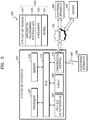
- FIG. 2 is a diagram of an electronic apparatus 201 in a network environment 200, according to various embodiments.
- the electronic apparatus 201 may include the electronic apparatus 100 of FIG. 1 .
- the electronic apparatus 201 may include a bus 210, a processor 220, a memory 230, an input and output interface 250, a display 260, and a communication interface 270. In some embodiments, the electronic apparatus 201 may omit at least one of the components or may further include other components.
- the bus 210 may interconnect the components 210 through 270, and may include a circuit to enable communication among the components 210 through 270, for example, the circuit to transmit a control message and/or data.
- the processor 220 may include one or more of a CPU, an AP, a communication processor (CP), and an image signal processor.
- the processor 220 may perform calculation or data processing related to controlling and/or communication of one or more other components of the electronic apparatus 201.
- the memory 230 may include a volatile and/or a nonvolatile memory.
- the memory 230 may store a command or data related to one or more other components of the electronic apparatus 201.
- the memory 230 may store software and/or a program 240.
- the program 240 may include, for example, a kernel 241, middleware 243, an application programming interface (API) 245, and/or an application program (or "an application") 247.
- At least one of the kernel 241, the middleware 243, and the API 245 may be referred to as an operating system (OS).
- OS operating system
- the kernel 241 may control or manage system resources (for example, the bus 210, the processor 220, the memory 230, or the like) used to execute operations or functions realized by other programs (for example, the middleware 243, the API 245, or the application program 247). Also, the kernel 241 may access separate components of the electronic apparatus 201 via the middleware 243, the API 245, or the application program 247, thereby providing an interface through which the system resources may be controlled or managed.
- system resources for example, the bus 210, the processor 220, the memory 230, or the like
- other programs for example, the middleware 243, the API 245, or the application program 247.
- the kernel 241 may access separate components of the electronic apparatus 201 via the middleware 243, the API 245, or the application program 247, thereby providing an interface through which the system resources may be controlled or managed.
- the middleware 243 may perform an intervention function such that the API 245 or the application program 247 may communicate and exchange data with the kernel 241.
- the middleware 243 may process one or more operation requests received from the application program 247 according to a priority order. For example, the middleware 243 may assign, to at least one of the application programs 247, a priority order to use the system resource (for example, the bus 210, the processor 220, the memory 230, or the like) of the electronic apparatus 201. For example, the middleware 243 may process the one or more operation requests according to the priority order assigned to the at least one of the application program 247, and thus, may perform scheduling or load balancing with respect to the one or more operation requests.
- a priority order for example, the system resource (for example, the bus 210, the processor 220, the memory 230, or the like) of the electronic apparatus 201.
- the middleware 243 may process the one or more operation requests according to the priority order assigned to the at least one of the application program 247, and thus, may perform scheduling or load balancing with respect to the one or more operation requests.
- the API 245 may be an interface via which the application program 247 may control a function provided by the kernel 241 or the middleware 243.
- the API 245 may include at least one interface or function (for example, an instruction) for controlling of a file, a window, or text, processing of an image, or the like.
- the input and output interface 250 may perform a function of an interface to transmit commands or data input from a user or other external apparatuses to (an)other component(s) of the electronic apparatus 201. Also, the input and output interface 250 may output commands or data received from the other component(s) of the electronic apparatus 201 to the user or other external apparatuses.
- the display 260 may include a liquid crystal display (LCD), an LED display, an organic LED (OLED) display, a microelectromechanical systems (MEMS) display, or an electronic paper display.
- the display 260 may display to the user various content, for example, text, an image, a video, an icon, a symbol, or the like.
- the display 260 may include a touch screen.
- the display 260 may receive a touch, a gesture, a proximity, or a hovering input using an electronic pen or part of a body of the user.
- the communication interface 270 may establish communication between the electronic apparatus 201 and an external apparatus (for example, a first external electronic apparatus 202, a second external electronic apparatus 204, or a server 206).
- the communication interface 270 may be connected to a network 262 via wireless communication or wired communication and may communicate with the external apparatus (for example, the second external electronic apparatus 204 or the server 206).
- the wireless communication may include, for example, a cellular communication protocol, and may include, for example, at least one of long-term evolution (LTE), LTE advance (LTE-A), code division multiple access (CDMA), wideband CDMA (WCDMA), a universal mobile telecommunication system (UMTS), wireless broadband (WiBro), and a global system for mobile communications (GSM).
- LTE long-term evolution
- LTE-A LTE advance
- CDMA code division multiple access
- WCDMA wideband CDMA
- UMTS universal mobile telecommunication system
- WiBro wireless broadband
- GSM global system for mobile communications
- the wireless communication may include, for example, short-range wireless communication 264.
- the short-range wireless communication 264 may include, for example, at least one of wireless fidelity (Wifi), Bluetooth, near field communication (NFC), and a global navigation satellite system (GNSS).
- WLAN global navigation satellite system
- the GNSS may include, for example, at least one of a global positioning system (GPS), a global navigation satellite system (Glonass), a Beidou navigation satellite system (hereinafter, "Beidou”), Galileo, and the European global satellite-based navigation system, based on a region of use or a bandwidth.
- GPS global positioning system
- Beidou Beidou navigation satellite system
- the wired communication may include, for example, at least one of a universal serial bus (USB), a high definition multimedia interface (HDMI), recommended standard 232 (RS-232), and a plain old telephone service (POTS).
- the network 262 may include a telecommunications network.
- the network 262 may include at least one of a computer network (for example, a local area network (LAN) or a wide area network (WAN)), the Internet, and a telephone network.
- Each of the first and second external electronic apparatuses 202 and 204 may be the same apparatus as the electronic apparatus 201 or a different apparatus from the electronic apparatus 201.
- the server 206 may include a group of one or more servers.
- all or part of operations executed by the electronic apparatus 201 may be executed by another electronic apparatus or a plurality of other electronic apparatuses (for example, the first and second external electronic apparatuses 202 and 204 or the server 206).
- the electronic apparatus 201 may request at least a function related to the certain function or service from the other electronic apparatuses (for example, the first and second external electronic apparatuses 202 and 204 or the server 206), additionally, or rather than the electronic apparatus 201 performs the certain function or service on its own.
- the other electronic apparatuses for example, the first and second external electronic apparatuses 202 and 204 or the server 206) may perform the requested function or an additional function and may transmit a result of the performance to the electronic apparatus 201.
- the electronic apparatus 201 may provide the requested function or service by intactly providing the received result or by additionally processing the received result.
- a cloud computing, a distributed computing, or a client-server computing technique may be used.
- the electronic apparatus 201 and the first and second external electronic apparatuses 202 and 204 may transmit an image captured by a camera of each of the electronic apparatus 201 and the first and second external electronic apparatuses 202 and 204 to one electronic apparatus by using the described communication methods and may synthesize the images into one image. For example, an image having a viewing angle of 180 degrees, captured by the electronic apparatus 201, and an image having a viewing angle of 180 degrees, captured by the second external electronic apparatus 202, may be synthesized to generate an image having a viewing angle of 360 degrees.
- FIG. 3 is a schematic block diagram of the electronic apparatus 100 illustrated in FIG. 1 .
- the electronic apparatus 100 may include a processor 310, a temporary memory 320, image sensor A 330, and image sensor B 340.
- the electronic apparatus 100 may include, for example, a touch panel, a physical key, a proximity sensor, and a biometric sensor, as an input module, and may include a memory, an analog/digital (A/D) converter, a power supply, etc.
- the processor 310 may denote a processor configured to control the image sensor A 330 and the image sensor B 330 and perform image processing by receiving image data.
- the image sensor A 330 and the image sensor B 340 may receive light incident through a lens (not shown) and convert the light into an electrical signal.
- the image sensor A 330 may be referred to as a first image sensor and the image sensor B 340 may be referred to as a second image sensor.
- the first and second image sensors 330 and 340 may include a pixel sensor configured to sense at least two mixed colors information, for example, a white (w) pixel and a brightness pixel.
- the first image sensor 330 and the second image sensor 340 may include a pixel array in which red (R), green (G), and blue (B), and white (W) pixel sensors are arranged in a set pattern.
- the temporary memory 320 may temporarily store image signals generated and read from the second image sensor 340.
- the temporary memory 320 may be provided separately from the processor 310, and may include a buffer memory or a line memory.
- the image signals may be indicated and stored as a general data format transmitted between electronic apparatuses.
- the temporary memory 320 may temporarily store image signals read from only one of the two image sensors 330 and 340. As illustrated in FIG. 3 , the image signal generated by the first image sensor 330 may be directly transmitted to the processor 310 without passing through the temporary memory 320, and the image signal generated by the second image sensor 340 may be temporarily stored in the temporary memory 320 and transmitted to the processor 310.
- the processor 310 may control the image signal stored in the temporary memory 320 to be received at a time point in which the reception of the image signal read from the first image sensor 330 is ended.
- the processor 310 must not receive a next image signal read from the first image sensor 330 while the processor 310 receives the image signal from the temporary memory 320, and thus, the processor 310 may insert a blanking period with respect to a read control signal output to the first image sensor 330, so as not to allow the image signals received from the first image sensor 330 and the second image sensor 340 to overlap each other. Aspects regarding the setting of the blanking period will be described below with reference to FIG. 8 .
- the electronic apparatus 100 may realize the temporary memory 320 configured to store the image signals output from the two image sensors 330 and 340 via only a line memory corresponding to the image signal output from one image sensor, for example, data of one horizontal line, thereby reducing the number of line memories that are needed. Also, the electronic apparatus 100 may process the image signals input from the two image sensors 330 and 340 like an image signal input from one image sensor.
- a camera including a plurality of sensors or lenses such as a three-dimensional (3D) camera, a dual camera, or a 360 degrees omnidirectional camera
- exposure is precisely simultaneously started and ended, and thus, even if a quick object is captured, a user may conveniently obtain an effect of capturing the object via one sensor.
- the electronic apparatus 100 includes the two image sensors 330 and 340.
- the electronic apparatus 100 may receive data by simultaneously or separately controlling the N image sensors based on a synchronization signal and a control signal, and may generate an image simultaneously merged, by using N-1 line memories.
- the processor 310 may control operations of the described components. For example, the processor 310 may generate a synchronization signal so that an image signal is generated at a certain time point or at a certain time interval. The processor 310 may control generated image signals to be sequentially transmitted to the temporary memory 320. For example, after some of signals generated by the image sensor A 330 may be transmitted to the temporary memory 320, some of signals generated by the image sensor B 340 may be transmitted to the temporary memory 320.
- the electronic apparatus 100 may additionally include an image processor (not shown) configured to process the image signals, or may have an image processor in the processor 310.
- the processor 310 processes the image.
- the processor 310 may perform various post-processing by using the image signals received via the temporary memory 320.
- the processor 310 may perform signal processing of gain adjustment or waveform standardization with respect to the received image signals.
- the processor 310 may perform a process of removing noise with respect to the image signals.
- the processor 310 may perform signal processing for image quality improvement, such as gamma correction, color filter array interpolation, color matrix, color correction, color enhancement, etc.
- FIG. 4 illustrates the image sensor module 401 of the electronic apparatus 100 according to an embodiment.
- the image sensor module 401 may include a covering member 450, a lens 410, a lens barrel 420, a coil portion 430, a magnet portion 440, a base 470, an image sensor 460, and a circuit substrate 480.
- the covering member 450 may form an exterior boundary of the image sensor module 401.
- the covering member 450 may protect various components arranged inside the image sensor module 401.
- the lens 410 may include a plurality of lenses.
- the plurality of lenses may include a lens moving for an auto-focus operation, a lens moving for a zooming operation, etc.
- An image obtained from the lens 410 may be transmitted to the image sensor 460.
- the lens barrel 420 may receive the lens 410 therein.
- the coil portion 430 may be arranged at the outside of the lens barrel 420.
- the magnet portion 440 may be arranged at a location corresponding to the coil portion 430.
- the magnet portion 440 may be arranged to face the coil portion 430.
- the electronic apparatus 100 may perform optical image stabilization with respect to user vibration, by moving the lens 410 based on interaction of electromagnetic fields or magnetic fields between the magnet portion 440 and the coil portion 430, by using an optical image stabilizer (OIS) driving module (not shown).
- OIS optical image stabilizer
- the electronic apparatus 100 may move the lens 410, based on the interaction of the electromagnetic field generated from the coil portion 430 and the magnetic field generated from the magnet portion 440, when power is applied to the coil portion 430. Via this, the electronic apparatus 100 may sense hand-shaking of the user and move the lens 410 in a direction opposite to a direction of the hand-shaking, so as to prevent blurriness in images.
- the electronic apparatus 100 may sense hand-shaking of the user and move the image sensor 460 in a direction opposite to a direction of the hand-shaking, so as to prevent blurriness in images.
- the base 470 may be coupled to the covering member 450.
- the base 470 may support a bottom side of the covering member 450.
- An infrared prevention filter may further be arranged on the base 470 at a location thereof corresponding to the image sensor 460.
- the base 470 may operate as a sensor holder configured to protect the image sensor 460.
- the image sensor 460 may be arranged on the circuit substrate 480.
- the image sensor 460 may be electrically connected to the circuit substrate 480 via wire-bonding or may be electrically connected to the circuit substrate 480 via flip bonding by using conductive pastes.
- the circuit substrate 480 may include a plurality of circuit patterns (not shown) and may transmit, to the processor 310, a signal converted by using the image sensor 460.
- the image sensor 460 may include a pixel array in which color pixel sensors (for example, R, G, B pixels) and white pixels (for example, W pixels) are arranged in a set pattern.
- the pixel array may convert an optical image signal of an external object, which is incident through the lens 410, into an electric image signal.
- FIG. 5 illustrates pixels 501 included in an image sensor of an electronic apparatus according to embodiments.
- each of the pixels 501 may convert an optical signal into an electrical signal.
- Each of the pixels 501 may include at least one micro-lens (not shown), at least one color filter 510, and at least one photodiode 520.
- the micro-lens may focus light incident from the outside.
- the color filter 510 may include at least one of a red filter, a green filter, a blue filter, a white filter, a cyan filter, a magenta filter, and a yellow filter.
- the photodiode 650 may convert an optical signal into an electrical signal.
- FIG. 6 is an example view for describing pixels included in an image sensor of an electronic apparatus according to embodiments.
- the red filter may allow light of a red wavelength range to pass therethrough.
- the green filter may allow light of a green wavelength range to pass therethrough.
- the blue filter may allow light of a blue wavelength range to pass therethrough.
- the white filter may allow light of all visible wavelength ranges to pass therethrough.
- the cyan filter may allow light of the green wavelength range and the blue wavelength range to pass therethrough.
- the magenta filter may allow light of the red wavelength range and the blue wavelength range to pass therethrough.
- the yellow filter may allow light of the red wavelength range and the green wavelength range to pass therethrough.
- FIG. 7 is a view for describing a situation in which an electronic apparatus transmits an image signal to a temporary memory 730, according to an embodiment.
- image sensors include 8x8 pixels.
- the processor 310 may capture an object by controlling the image sensor module 401 illustrated in FIG. 4 .
- the processor 310 may control a plurality of image sensors A and B 710 and 720 to substantially simultaneously capture the object by using a synchronization signal, etc.
- the image sensors A and B 710 and 720 may convert a received optical signal into an image signal.
- the image sensors A and B 710 and 720 may transmit a charge generated in each of pixels 711 and 721, that is, the optical signal, to the processor 310.
- the image signal read from the image sensor A 710 may be directly transmitted to the processor 310 and the image signal read from the image sensor B 720 may be transmitted to the temporary memory 730.
- the image sensors A and B 710 and 720 may transmit the image signals to the processor 310 and the temporary memory 730 based on each line.
- the image sensor A 710 may transmit the image signal to the processor 310 from a first line 715.
- the image sensor B 720 may transmit the image signal to the temporary memory 730 from a first line 725. Accordingly, there is only a space in the temporary memory 730 to receive data of the first line 725 of the image sensor B 720, and thus, the received data may be smoothly output to the processor 310.
- the temporary memory 730 may output, to the processor 310, the data of the first line 725, the data being read from the image sensor B 720 and stored in the temporary memory 730 when the processor 310 finishes receiving the data of the first line 715, the data being read from the image sensor A 710.
- the electronic apparatus may simultaneously receive, from the processor 310, the image signal read from each of the image sensors A and B 710 and 720, and generate a merged image, by including only one temporary memory, for example, only a line of the image sensor B 720, that is, the line memory configured to store data of 8 pixels.
- the processor 310 may not receive next image signals a9 through a16 from the image sensor A 710, while receiving the image signal from the temporary memory 730, and thus, may set a section before outputting a next horizontal synchronization signal or a next read control signal configured to control the image signal to be read from the image sensor A 710, as a blanking period.
- the processor 310 may form one line by connecting the first line 715 received from the image sensor A 710 and the first line 725 received from the image sensor B 720. By repeating this process, the processor 310 may generate one image by synthesizing an image generated by the image sensor A 710 and an image generated by the image sensor B 720.
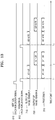
- FIG. 8 is a view for describing a process in which an electronic apparatus transmits an image signal based on a synchronization signal of the processor 310, according to an embodiment.
- the processor 310 may control each of the image sensors A and B 710 and 720 by using a vertical synchronization signal 810 and a horizontal synchronization signal 812.
- the vertical synchronization signal 810 is configured to synchronize each of frames
- the horizontal synchronization signal 812 is configured to synchronize each of lines included in the frames.
- the vertical synchronization signal 810 and/or the horizontal synchronization signal 812 may be a read control signal configured to control data to be read from each of the image sensors A and B 710 and 720.
- the processor 310 may simultaneously or sequentially output the read control signals output to the image sensor A 710 and the image sensor B 720.
- the processor 310 may synchronize or asynchronize the read control signals and output the read control signals to the image sensors A and B 710 and 720.
- the image sensor A 710 may transmit the image signal or data corresponding to the first line 715, to the processor 310.
- the processor 310 may start to receive the data of the first line 715.
- the image sensor B 720 may output the data of the first line 725 to the temporary memory 730, and the data of the first line 725 may be sequentially stored in the temporary memory 730.
- the reception of the data from the image sensor A 710 may be ended, and the data in the temporary memory 730 may be output to the processor 310.
- the processor 310 may control data a9 through a16 of a second line not to be received from the image sensor A 710 while receiving the data from the temporary memory 730.
- a timing of the horizontal synchronization signal 812 configured to control the reception of the data a9 through a16 of the second line from the image sensor A 710 may be controlled.
- a section between the time point T2 in which the data is received from the temporary memory 730 and a time point T3 in which the data a9 through a16 of the second line is received from the image sensor A 710 may be set as a blanking period.
- the processor 310 may receive the data a9 through a16 of the second line from the image sensor A 710 in response to a next horizontal synchronization signal, and data b9 through b16 read from the image sensor B 720 may be stored again in the temporary memory 730. Then, the processor 310 may receive the data b9 through b16 stored in the temporary memory 730 at a time point when the processor 310 finishes receiving the data a9 through a16 from the image sensor A 710.
- the processor 310 may smoothly receive the data output from the two image sensors A and B 710 and 720 by using only the line memory corresponding to one line of the image sensor B 720, by inserting a certain blanking period in a section in which the data received from the image sensor A 710 is read.
- the processor 310 may connect two lines, that is, horizontal lines of the imaging devices 710 and 720, into one line, when all of the data of the first line 715 of the image sensor A 710 and all of the data of the first line 725 of the image sensor B 720 are received. Also, the processor 310 may accumulate and merge all lines from the image sensors A and B 710 and 720 and may generate one image.
- FIG. 9 is a flowchart of a method of controlling the electronic apparatus 100, according to another embodiment.
- the electronic apparatus 100 may generate a capturing signal based on an event, such as a user input, etc.
- the electronic apparatus 100 may capture an object by operating, for example, the image sensor module 401.
- the electronic apparatus 100 may capture the object by using the image sensor A 710 and the image sensor B 720.
- the electronic apparatus 100 may directly transmit the first line 715 of the image sensor A 710 to the processor 310, without passing through the temporary memory 730.
- the processor 310 may start to store the first line 725 of the image sensor B 720 in the temporary memory 730.
- operations S930 and S940 may be simultaneously or time-sequentially performed.
- the processor 310 may merge the first line 715 of the image sensor A 710 and the first line 725 of the image sensor B 720 into one continuous line.
- the processor 310 may generate merged image data of one horizontal line, after receiving all of the data of the first lines 715 and 725 or the horizontal lines of the image sensor A 710 and the image sensor B 720.
- the processor 310 may generate image data merged in a frame unit after receiving all of data of second and third lines after receiving all of the data of the first lines 715 and 725 or the horizontal lines of the image sensor A 710 and the image sensor B 720.
- the electronic apparatus 100 may generate one synthesized image by repeating these operations with respect to the lines transmitted from the image sensors A and B 710 and 720.
- hardware may be formed by using only a temporary memory corresponding to one line of one image sensor with respect to the data read from a plurality of image sensors, and a timing of a synchronization signal of the image sensors may be adjusted so that the data read from the plurality of image sensors may be efficiently stored and a synthesized image may be generated, by having a minimum capacity of the temporary memory.
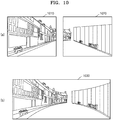
- FIG. 10 is a view of a result of merging two images into one image via the electronic apparatus 100, according to an embodiment.
- image 1 1010 may be an image generated by the image sensor A 710.
- the image sensor A 710 may include, for example, an image sensor included in the camera 150 located at the front surface of the electronic apparatus 100 illustrated in FIG. 1 .
- the image 1 1010 may include, for example, an image having a viewing angle of 180 degrees.
- Image 2 1020 may include an image generated by the image sensor B 720.
- the image sensor B 720 may include, for example, an image sensor included in the camera 150' located at a surface opposite to the front surface of the electronic apparatus 100 of FIG. 1 .
- the image 2 1020 may include an image having a viewing angle of 180 degrees.
- image 3 1030 may be an image generated by merging the image 1 1010 and the image 2 1020.
- Each of the image 1 1010 and the image 2 1020 has the viewing angle of 180 degrees, and thus, the image 1030 generated by merging the two images may have a viewing angle of 360 degrees.
- a user may easily obtain an image having a viewing angle of 360 degrees via one time capturing.
- FIG. 11 is a view of a result of synthesizing four images into one image, via the electronic apparatus 100, according to an embodiment.
- image 1 1110 may be an image generated by a first image sensor, and may be, for example, an image having a viewing angle of 90 degrees.
- Image 2 1120 may be an image generated by a second image sensor, and may be, for example, an image having a viewing angle of 90 degrees.
- Image 3 1130 may be an image generated by a third image sensor, and may be, for example, an image having a viewing angle of 90 degrees.
- Image 4 1140 may be an image generated by a fourth image sensor, and may be, for example, an image having a viewing angle of 90 degrees.
- image 5 1150 may be an image generated by merging the image 1 1310, the image 2 1320, the image 3 1330, and the image 4 1340.
- Each of the images has the viewing angle of 90 degrees, and thus, the image 5 1150 in which the images are merged may have a viewing angle of 360 degrees.
- a user may easily obtain an image having a viewing angle of 360 degrees via one time capturing.
- FIG. 12 is a flowchart of a method of controlling an electronic apparatus, according to another embodiment.
- a processor may output a first read control signal to a first image sensor and receive first data that is read.
- the processor may output a second read control signal to a second image sensor and store second data that is read in a temporary memory.
- Operations S1200 and S1210 may be simultaneously or sequentially performed.
- the first read control signal and the second read control signal may be horizontal synchronization signals or sensor control signals corresponding to the horizontal synchronization signals, output to the image sensors.
- the processor may control the second data stored in the temporary memory to be output based on an output control signal generated between the first read control signal and a next first read control signal.
- a blanking period may be inserted between the first read control signal for reading data of a first line of the first image sensor and the next first read control signal for reading data of a second line of the first image sensor.
- the processor may receive the second data stored in the temporary memory after receiving the first data from the first image sensor, and may not receive the data from the first image sensor while receiving the second data.
- a length of the blanking period may be variably set by taking into account the number of image sensors, a size of one line of the image sensors, etc.
- the processor may generate merged data in which the first data and the second data are merged.
- the use of the temporary memory may be minimized, and even if a data input clock and a data output clock are the same, it may not be inconvenient for the processor to synthesize a plurality of pieces of image data.
- FIG. 13 is a view for describing a situation in which an electronic apparatus transmits an image signal to a temporary memory.
- the electronic apparatus according to the embodiment of FIG. 13 does not include an additional temporary memory.
- read timings of the image sensor A 710 and the image sensor B 720 may be adjusted so that the image sensor A 710 and the image sensor B 720 may sequentially output data to the processor 310 without a temporary memory.
- the processor 310 may control the image sensors A and B 710 and 720 by using the vertical synchronization signal 810 and the horizontal synchronization signal 812.
- the processor 310 may start to receive the data a1 through a8 of the first line 715.
- Data b1 through b8 of the first line 725 of the image sensor B 720 may be started to be output to the processor 310, at a timing in which the processor 310 finishes receiving the data a1 through a8 of the first line 715. That is, the sensor output timings of the image sensor A 710 and the image sensor B 720 may have a difference between the time point T2 and the time point T1.
- the processor 310 may control the data not to be received from the image sensor A 710, while receiving the data b1 through b8 from the image sensor B 720. To this end, the processor 310 may control a timing of the horizontal synchronization signal 812 configured to control receiving data a9 through a16 of a second line from the image sensor A 710. That is, a blanking period may be set between the time point T2 in which the data is received from the temporary memory 730 and a time point T3 in which the data a9 through a16 of the second line is received from the image sensor A 710.
- the processor 310 may receive the data a9 through a16 of the second line from the image sensor A 710 in response to a next horizontal synchronization signal, after receiving all of the data b1 through b8 from the image sensor B 720 after receiving all of the data a1 through a8 from the image sensor A 710. Also, the processor 310 may receive data b9 through b16 of a next line from the image sensor B 720 at a time point when the processor 310 finishes receiving the data a9 through al6 from the image sensor A 710.
- the processor 310 may control the data read timings of the image sensor A 710 and the image sensor B 720 to be different, and may set a certain blanking period with respect to the read control signal of the image sensor A 710, so as to receive the data from the image sensor A 710 and the image sensor B 720 in a non-overlapped manner and generate image data simultaneously merged, without using a temporary memory.
- At least one of apparatuses may be implemented as computer instructions which may be executed by various computer means, and recorded on a non-transitory computer-readable recording medium.
- a processor for example, the processor 310
- one or more processors may perform functions corresponding to the instructions.
- the non-transitory computer-readable recording medium may include, for example, the memory 130.
- the non-transitory computer-readable recording medium may include a hard disk, a floppy disk, magnetic media (e.g., magnetic tapes), optical media (e.g., compact disc-read only memories (CD-ROMs), or digital versatile discs (DVDs)), magneto-optical media (e.g., floptical disks), and hardware devices (e.g., read only memory (ROM), random access memory (RAM), or flash memories).
- Examples of the program commands include a high-level programming language code that may be executed by a computer using an interpreter as well as a machine language code made by a complier.
- the hardware devices may be configured to operate as one or more software modules to perform operations according to various embodiments, and vice versa.
Landscapes
- Engineering & Computer Science (AREA)
- Multimedia (AREA)
- Signal Processing (AREA)
- Physics & Mathematics (AREA)
- Spectroscopy & Molecular Physics (AREA)
- Computing Systems (AREA)
- Theoretical Computer Science (AREA)
- Human Computer Interaction (AREA)
- Studio Devices (AREA)
Description
- The present disclosure relates to an electronic apparatus and a method of controlling the electronic apparatus, and more particularly, to an efficient use of a memory by controlling a read time of an image signal generated by a plurality of image sensors.
- An electronic apparatus may process an image obtained by an image sensor. Also, recent electronic apparatuses have reached the stage of mobile convergence encompassing the functionality of other apparatuses. Electronic apparatuses may provide a call function and a message exchange function, and may further provide a photographing function, etc., by including an image sensor.
- The image sensor may convert received optical signals into electrical signals via pixels. The pixels may be arranged in a pixel array of a pre-set color pattern. For example, the pixels of the image sensor may include red (R), green (G), and blue (B) pixels, and the red (R), green (G), and blue (B) pixels may be arranged in the pixel array of the pre-set color pattern. Also, the pixels may be arranged in a pixel array of a color and brightness pattern. For example, the pixels of the image sensor may include red (R), green (G), blue (B), and white (W) pixels, and the red (R), green (G), blue (B), and white (W) pixels may be arranged in the pixel array of the pre-set color pattern.
- A single image sensor or two or more image sensors may be provided in an electronic apparatus. The electronic apparatus may synthesize images captured by the two or more image sensors and generate one image. For instance,
US 2009/0128854 A1 describes using several adjacent image sensors, capturing overlapping images, and using the data from the multiple sensors to correct for a position shift amount.US 2003/0222987 A1 describes a line scan image recording device with an internal system for delaying signals from multiple photosensor arrays. The imaging apparatus described inUS 2015/0070530 A1 has a single sensor, but data from a part of the captured image is pre-processed apart from data from the remainder of the image.US 2011/0242342 describes a way to combine data from multiple image sensors using a combiner including a line buffer. The devices and methods described inUS 2010/0259798 A1 andUS 2013/0235149 also include multiple sensors. - When photographing is performed by using a plurality of image sensors, and data read from the plurality of image sensors is stored or processed, an increased amount of hardware of an electronic apparatus is required to provide a temporary memory or a processing circuit based on the amount of data read from each image sensor, and the increased amount of hardware may increase overall expenses.
- Thus, provided are an electronic apparatus and a method of controlling the electronic apparatus according to various embodiments. The electronic apparatus is configured to optimize a capacity of a temporary memory and efficiently form hardware, by adjusting read timings of data read from a plurality of image sensors.
- According to an aspect of the present disclosure, an electronic apparatus is provided according to any of claims 1-4
- According to another aspect of the present disclosure, a method of controlling an electronic apparatus including a plurality of image sensors including a first image sensor and a second image sensor is provided according to any of claims 5-7.
- According to another aspect of the present disclosure, a non-transitory recording medium has recorded thereon a program for executing the method of controlling the electronic apparatus.
- According to the embodiments, an electronic apparatus may efficiently store data read from a plurality of image sensors while having a minimum capacity of a temporary memory, and may generate a synthesized image.
-
-
FIG. 1 is a view of an exterior shape of an electronic apparatus according to an embodiment. -
FIG. 2 is a diagram of an electronic apparatus in a network environment, according to embodiments. -
FIG. 3 is a schematic block diagram of the electronic apparatus illustrated inFIG. 1 . -
FIG. 4 is an example view for describing an image sensor module of the electronic apparatus illustrated inFIG. 1 . -
FIG. 5 is an example view for describing pixels included in an image sensor of the electronic apparatus illustrated inFIG. 1 . -
FIG. 6 is an example view for describing pixels included in the image sensor of the electronic apparatus illustrated inFIG. 1 . -
FIG. 7 is a view for describing a process of transmitting an image signal via an electronic apparatus, according to an embodiment. -
FIG. 8 is a view for describing a process of transmitting an image signal based on a synchronization signal of a processor, via an electronic apparatus, according to an embodiment. -
FIG. 9 is a flowchart of a method of controlling an electronic apparatus, according to another embodiment. -
FIGS. 10 and11 illustrate results of synthesizing a plurality of images into one image, via an electronic apparatus, according to an embodiment. -
FIG. 12 is a flowchart of a method of controlling an electronic apparatus, according to another embodiment. -
FIG. 13 is a view for describing a process of transmitting an image signal based on a synchronization signal of a processor, via an electronic apparatus. - Hereinafter, various embodiments will be described with reference to the accompanying drawings. However, the embodiments should not be construed as limiting the technical concept of the present disclosure, and it will be understood to encompass various modifications, equivalents, and/or alternatives. Regarding the description of the drawings, like reference numerals may refer to the like elements.
- In the present disclosure, when a part "has," "may have," "includes," or "may include" an element, it is to be understood that the part includes the element (for example, a numeral value, a function, an operation, a component, or the like), while the part does not exclude other additional elements.
- In the present disclosure, expressions, such as "A or B," "at least one of A and/or B," "one or more of A and/or B," etc., may include all possible combinations of arranged items. For example, expressions "A or B," "at least one of A and B," and "at least one of A or B" may refer to all of the cases (1) including at least one A, (2) including at least one B, and (3) including both at least one A and at least one B.
- Expressions, such as "first," "second," etc., used in this disclosure may modify various components irrespective of an order and/or importance, and may be used to distinguish one element from other elements and should not be construed as limiting the components. For example, a first user device and a second user device may indicate different user devices, irrespective of an order or importance. That is, a first component may be referred to as a second component, and alternatively, a second component may be referred to as a first component, without departing from the scope of the present disclosure as defined by the claims.
- A term used in the present disclosure "configured to" may be alternatively used as, for example, "suitable for," "having the capacity to," "designed to," "adapted to," "made to," or "capable of," depending on situations. The term "configured to" may not necessarily denote "specifically designed to" in a hardware manner. Rather, in some situations, an expression "a device configured to" may denote that the device is "capable of doing something" with other devices or components. For example, an expression "a processor configured to perform A, B, and C" may denote an exclusive processor (for example, an embedded processor) configured to perform the operations, or a generic-purpose processor (for example, a central processing unit (CPU) or an application processor (AP)) configured to perform the operations by executing one or more software programs stored in a memory device.
- The terms used herein are for the purpose of describing particular embodiments only and are not intended to be limiting of the present disclosure. As used herein, the singular forms "a," "an" and "the" are intended to include the plural forms as well, unless the context clearly indicates otherwise. All terms (including technical and scientific terms) used herein have the same meaning as commonly understood by one of ordinary skill in the art to which the present disclosure belongs. It will be further understood that terms, such as those defined in commonly used dictionaries, should be interpreted as having a meaning that is consistent with their meaning in the context of the relevant art, and, unless clearly defined otherwise, will not be interpreted in an idealized or overly formal sense. Depending on cases, although some terms are defined in the present disclosure, they should not be interpreted to exclude embodiments of the present disclosure.
- An electronic apparatus according to embodiments may include, for example, at least one of a smartphone, a tablet personal computer (PC), a mobile phone, a video phone, an electronic(e)-book reader, a desktop PC, a laptop PC, a netbook computer, a workstation, a server, a personal digital assistant (PDA), a portable multimedia player (PMP), an MP3 player, a mobile medical device, a camera, and a wearable device. According to embodiments, the wearable device may include at least one of an accessory-type wearable device (for example, a watch, a ring, a bracelet, an anklet, a necklace, glasses, contact lenses, or a head-mounted-device (HMD)), a fabric or clothing-integrated-type wearable device (for example, electronic clothing), a body-mounted-type wearable device (for example, a skin pad or tattoos), and a bio-implantable circuit-type wearable device.
- In some embodiments, the electronic apparatus may include home appliances. The home appliances may include, for example, at least one of a television, a digital video disk (DVD) player, an audio player, a refrigerator, an air-conditioner, a vacuum cleaner, an oven, a microwave, a laundry machine, an air-cleaner, a set-top box, a home automation control panel, a security control panel, a TV box, a game console, an electronic dictionary, an electronic key, a camcorder, and an electronic frame.
- According to other embodiments, the electronic apparatus may include at least one of: various medical devices (for example, various portable medical measuring devices (a blood sugar measuring device, a heartbeat measuring device, a blood pressure measuring device, a body-temperature measuring device, or the like), magnetic resonance angiography (MRA), magnetic resonance imaging (MRI), computed tomography (CT), ultrasonic devices, or the like); a navigation device; a global navigation satellite system (GNSS); an event data recorder (EDR); a flight data recorder (FDR); a vehicle infotainment device; electronic equipment for a ship (for example, a navigation device for a ship, a gyrocompass, etc.); an avionics device; a security device; a vehicle head unit; an industrial or a household robot; an automatic teller's machine of financial institutions; a point of sales of a store; and Internet of things (IoT) devices (for example, a bulb, various sensors, an electricity or gas meter, a sprinkler, a fire alarm, a thermostat, a streetlight, a toaster, sports equipment, a hot-water tank, a heater, a boiler, etc.).
- In some embodiments, the electronic apparatus may include at least one of furniture, a part of a building/structure, an electronic board, an electronic signature receiving device, a projector, and various measuring devices (for example, waterworks, electricity, gas, and radio wave measuring devices). According to embodiments, the electronic apparatus may include a combination of one or more of the described apparatuses.
- In some embodiments, the electronic apparatus may include a flexible electronic apparatus. Also, the electronic apparatus according to the present disclosure are not limited to the apparatuses described above, and may include new electronic apparatuses according to the development of technology.
- Hereinafter, electronic apparatuses according to embodiments will be described by referring to the accompanying drawings. In this specification, a term "user" may refer to a person using an electronic apparatus, or an apparatus using an electronic apparatus, for example, an artificial intelligence (AI) electronic apparatus.
-
FIG. 1 is a view of an exterior shape of anelectronic apparatus 100 according to an embodiment. - Referring to
FIG. 1 , theelectronic apparatus 100 may be embodied as devices for various purposes. For example, theelectronic apparatus 100 may be embodied, for example, as a cellular phone, a smartphone, a notebook computer, a tablet device, etc., as described above, but is not limited thereto. - Referring to (a) of
FIG. 1 , adisplay 110 may be mounted at afront surface 101 of theelectronic apparatus 100. Aspeaker 120 configured to receive a voice of the other party may be mounted above thedisplay 110. A microphone 103 configured to transmit a voice of a user of theelectronic apparatus 100 may be mounted under thedisplay 110. - According to an embodiment, components configured to perform various functions of the
electronic apparatus 100 may be arranged around thespeaker 120. The components may include at least onesensor module 140. The at least onesensor module 140 may include, for example, at least one of an illuminance sensor (for example, an optical sensor), a proximity sensor, an infrared sensor, and an ultrasonic sensor. The components may include acamera 150. According to an embodiment, the components may include a light-emitting diode (LED)indicator 160 configured to inform the user of information about a state of theelectronic apparatus 100. - The
electronic apparatus 100 may capture an object by using thecamera 150. (b) ofFIG. 1 is a side view of theelectronic apparatus 100. Referring to (b) ofFIG. 1 , theelectronic apparatus 100 may further include a camera 150'. However, theelectronic apparatus 100 is not limited thereto, and may further include cameras. Thecameras 150 and 150' of theelectronic apparatus 100 may form various viewing angles. The viewing angles may include, for example, 30 degrees, 50 degrees, 90 degrees, and 180 degrees. Theelectronic apparatus 100 may generate images captured by thecameras 150 and 150' as separate images or may synthesize the captured images into one image. For example, when thecameras 150 and 150' have the viewing angles of 180 degrees, theelectronic apparatus 100 may generate an image having a viewing angle of 360 degrees. A camera which may capture an image having the viewing angle of 360 degrees may be referred to as an omnidirectional camera or a 360 degrees camera. Theelectronic apparatus 100 according to embodiments is not limited to the omnidirectional camera or the 360 degrees camera, and may include a plurality of cameras or a camera capable of synthesizing a plurality of images captured by a plurality of image sensors. -
FIG. 2 is a diagram of anelectronic apparatus 201 in anetwork environment 200, according to various embodiments. Theelectronic apparatus 201 may include theelectronic apparatus 100 ofFIG. 1 . - Referring to
FIG. 2 , theelectronic apparatus 201 may include abus 210, aprocessor 220, amemory 230, an input andoutput interface 250, adisplay 260, and acommunication interface 270. In some embodiments, theelectronic apparatus 201 may omit at least one of the components or may further include other components. - The
bus 210 may interconnect thecomponents 210 through 270, and may include a circuit to enable communication among thecomponents 210 through 270, for example, the circuit to transmit a control message and/or data. - The
processor 220 may include one or more of a CPU, an AP, a communication processor (CP), and an image signal processor. Theprocessor 220 may perform calculation or data processing related to controlling and/or communication of one or more other components of theelectronic apparatus 201. - The
memory 230 may include a volatile and/or a nonvolatile memory. For example, thememory 230 may store a command or data related to one or more other components of theelectronic apparatus 201. According to an embodiment, thememory 230 may store software and/or aprogram 240. Theprogram 240 may include, for example, akernel 241,middleware 243, an application programming interface (API) 245, and/or an application program (or "an application") 247. At least one of thekernel 241, themiddleware 243, and theAPI 245 may be referred to as an operating system (OS). - For example, the
kernel 241 may control or manage system resources (for example, thebus 210, theprocessor 220, thememory 230, or the like) used to execute operations or functions realized by other programs (for example, themiddleware 243, theAPI 245, or the application program 247). Also, thekernel 241 may access separate components of theelectronic apparatus 201 via themiddleware 243, theAPI 245, or theapplication program 247, thereby providing an interface through which the system resources may be controlled or managed. - For example, the
middleware 243 may perform an intervention function such that theAPI 245 or theapplication program 247 may communicate and exchange data with thekernel 241. - Also, the
middleware 243 may process one or more operation requests received from theapplication program 247 according to a priority order. For example, themiddleware 243 may assign, to at least one of theapplication programs 247, a priority order to use the system resource (for example, thebus 210, theprocessor 220, thememory 230, or the like) of theelectronic apparatus 201. For example, themiddleware 243 may process the one or more operation requests according to the priority order assigned to the at least one of theapplication program 247, and thus, may perform scheduling or load balancing with respect to the one or more operation requests. - For example, the
API 245 may be an interface via which theapplication program 247 may control a function provided by thekernel 241 or themiddleware 243. For example, theAPI 245 may include at least one interface or function (for example, an instruction) for controlling of a file, a window, or text, processing of an image, or the like. - For example, the input and
output interface 250 may perform a function of an interface to transmit commands or data input from a user or other external apparatuses to (an)other component(s) of theelectronic apparatus 201. Also, the input andoutput interface 250 may output commands or data received from the other component(s) of theelectronic apparatus 201 to the user or other external apparatuses. - For example, the
display 260 may include a liquid crystal display (LCD), an LED display, an organic LED (OLED) display, a microelectromechanical systems (MEMS) display, or an electronic paper display. For example, thedisplay 260 may display to the user various content, for example, text, an image, a video, an icon, a symbol, or the like. Thedisplay 260 may include a touch screen. For example, thedisplay 260 may receive a touch, a gesture, a proximity, or a hovering input using an electronic pen or part of a body of the user. - For example, the
communication interface 270 may establish communication between theelectronic apparatus 201 and an external apparatus (for example, a first externalelectronic apparatus 202, a second externalelectronic apparatus 204, or a server 206). For example, thecommunication interface 270 may be connected to a network 262 via wireless communication or wired communication and may communicate with the external apparatus (for example, the second externalelectronic apparatus 204 or the server 206). - The wireless communication may include, for example, a cellular communication protocol, and may include, for example, at least one of long-term evolution (LTE), LTE advance (LTE-A), code division multiple access (CDMA), wideband CDMA (WCDMA), a universal mobile telecommunication system (UMTS), wireless broadband (WiBro), and a global system for mobile communications (GSM). Also, the wireless communication may include, for example, short-
range wireless communication 264. The short-range wireless communication 264 may include, for example, at least one of wireless fidelity (Wifi), Bluetooth, near field communication (NFC), and a global navigation satellite system (GNSS). The GNSS may include, for example, at least one of a global positioning system (GPS), a global navigation satellite system (Glonass), a Beidou navigation satellite system (hereinafter, "Beidou"), Galileo, and the European global satellite-based navigation system, based on a region of use or a bandwidth. Hereinafter, in this specification, the "GPS" may be interchangeably used with the "GNSS." The wired communication may include, for example, at least one of a universal serial bus (USB), a high definition multimedia interface (HDMI), recommended standard 232 (RS-232), and a plain old telephone service (POTS). The network 262 may include a telecommunications network. For example, the network 262 may include at least one of a computer network (for example, a local area network (LAN) or a wide area network (WAN)), the Internet, and a telephone network. - Each of the first and second external
electronic apparatuses electronic apparatus 201 or a different apparatus from theelectronic apparatus 201. According to an embodiment, theserver 206 may include a group of one or more servers. According to embodiments, all or part of operations executed by theelectronic apparatus 201 may be executed by another electronic apparatus or a plurality of other electronic apparatuses (for example, the first and second externalelectronic apparatuses electronic apparatus 201 is to perform a certain function or service automatically or in response to a request, theelectronic apparatus 201 may request at least a function related to the certain function or service from the other electronic apparatuses (for example, the first and second externalelectronic apparatuses electronic apparatus 201 performs the certain function or service on its own. The other electronic apparatuses (for example, the first and second externalelectronic apparatuses electronic apparatus 201. Theelectronic apparatus 201 may provide the requested function or service by intactly providing the received result or by additionally processing the received result. To this end, for example, a cloud computing, a distributed computing, or a client-server computing technique may be used. - According to an embodiment, the
electronic apparatus 201 and the first and second externalelectronic apparatuses electronic apparatus 201 and the first and second externalelectronic apparatuses electronic apparatus 201, and an image having a viewing angle of 180 degrees, captured by the second externalelectronic apparatus 202, may be synthesized to generate an image having a viewing angle of 360 degrees. -
FIG. 3 is a schematic block diagram of theelectronic apparatus 100 illustrated inFIG. 1 . - Referring to
FIG. 3 , theelectronic apparatus 100 may include aprocessor 310, atemporary memory 320,image sensor A 330, andimage sensor B 340. - For example, the
electronic apparatus 100 may include, for example, a touch panel, a physical key, a proximity sensor, and a biometric sensor, as an input module, and may include a memory, an analog/digital (A/D) converter, a power supply, etc. Here, theprocessor 310 may denote a processor configured to control theimage sensor A 330 and theimage sensor B 330 and perform image processing by receiving image data. - The
image sensor A 330 and theimage sensor B 340 may receive light incident through a lens (not shown) and convert the light into an electrical signal. Theimage sensor A 330 may be referred to as a first image sensor and theimage sensor B 340 may be referred to as a second image sensor. The first andsecond image sensors first image sensor 330 and thesecond image sensor 340 may include a pixel array in which red (R), green (G), and blue (B), and white (W) pixel sensors are arranged in a set pattern. - The
temporary memory 320 may temporarily store image signals generated and read from thesecond image sensor 340. Thetemporary memory 320 may be provided separately from theprocessor 310, and may include a buffer memory or a line memory. The image signals may be indicated and stored as a general data format transmitted between electronic apparatuses. Thetemporary memory 320 may temporarily store image signals read from only one of the twoimage sensors FIG. 3 , the image signal generated by thefirst image sensor 330 may be directly transmitted to theprocessor 310 without passing through thetemporary memory 320, and the image signal generated by thesecond image sensor 340 may be temporarily stored in thetemporary memory 320 and transmitted to theprocessor 310. Theprocessor 310 may control the image signal stored in thetemporary memory 320 to be received at a time point in which the reception of the image signal read from thefirst image sensor 330 is ended. Theprocessor 310 must not receive a next image signal read from thefirst image sensor 330 while theprocessor 310 receives the image signal from thetemporary memory 320, and thus, theprocessor 310 may insert a blanking period with respect to a read control signal output to thefirst image sensor 330, so as not to allow the image signals received from thefirst image sensor 330 and thesecond image sensor 340 to overlap each other. Aspects regarding the setting of the blanking period will be described below with reference toFIG. 8 . Theelectronic apparatus 100 according to the present embodiment may realize thetemporary memory 320 configured to store the image signals output from the twoimage sensors electronic apparatus 100 may process the image signals input from the twoimage sensors - It is described that the
electronic apparatus 100 according to the present embodiment includes the twoimage sensors electronic apparatus 100 includes N (N is an integer equal to or greater than 2) image sensors, theelectronic apparatus 100 may receive data by simultaneously or separately controlling the N image sensors based on a synchronization signal and a control signal, and may generate an image simultaneously merged, by using N-1 line memories. - The
processor 310 may control operations of the described components. For example, theprocessor 310 may generate a synchronization signal so that an image signal is generated at a certain time point or at a certain time interval. Theprocessor 310 may control generated image signals to be sequentially transmitted to thetemporary memory 320. For example, after some of signals generated by theimage sensor A 330 may be transmitted to thetemporary memory 320, some of signals generated by theimage sensor B 340 may be transmitted to thetemporary memory 320. - The
electronic apparatus 100 may additionally include an image processor (not shown) configured to process the image signals, or may have an image processor in theprocessor 310. Hereinafter, it is assumed that theprocessor 310 processes the image. Theprocessor 310 may perform various post-processing by using the image signals received via thetemporary memory 320. For example, theprocessor 310 may perform signal processing of gain adjustment or waveform standardization with respect to the received image signals. - The
processor 310 may perform a process of removing noise with respect to the image signals. For example, theprocessor 310 may perform signal processing for image quality improvement, such as gamma correction, color filter array interpolation, color matrix, color correction, color enhancement, etc. - Each of the first and
second image sensors image sensor module 401.FIG. 4 illustrates theimage sensor module 401 of theelectronic apparatus 100 according to an embodiment. - Referring to
FIG. 4 , theimage sensor module 401 according to various embodiments may include a coveringmember 450, alens 410, alens barrel 420, acoil portion 430, amagnet portion 440, abase 470, animage sensor 460, and acircuit substrate 480. - The covering
member 450 may form an exterior boundary of theimage sensor module 401. The coveringmember 450 may protect various components arranged inside theimage sensor module 401. - The
lens 410 may include a plurality of lenses. For example, the plurality of lenses may include a lens moving for an auto-focus operation, a lens moving for a zooming operation, etc. An image obtained from thelens 410 may be transmitted to theimage sensor 460. - The
lens barrel 420 may receive thelens 410 therein. Thecoil portion 430 may be arranged at the outside of thelens barrel 420. Themagnet portion 440 may be arranged at a location corresponding to thecoil portion 430. Themagnet portion 440 may be arranged to face thecoil portion 430. According to embodiments, theelectronic apparatus 100 may perform optical image stabilization with respect to user vibration, by moving thelens 410 based on interaction of electromagnetic fields or magnetic fields between themagnet portion 440 and thecoil portion 430, by using an optical image stabilizer (OIS) driving module (not shown). - For example, the
electronic apparatus 100 may move thelens 410, based on the interaction of the electromagnetic field generated from thecoil portion 430 and the magnetic field generated from themagnet portion 440, when power is applied to thecoil portion 430. Via this, theelectronic apparatus 100 may sense hand-shaking of the user and move thelens 410 in a direction opposite to a direction of the hand-shaking, so as to prevent blurriness in images. Theelectronic apparatus 100 according to an embodiment may sense hand-shaking of the user and move theimage sensor 460 in a direction opposite to a direction of the hand-shaking, so as to prevent blurriness in images. - The base 470 may be coupled to the covering
member 450. The base 470 may support a bottom side of the coveringmember 450. An infrared prevention filter may further be arranged on the base 470 at a location thereof corresponding to theimage sensor 460. The base 470 may operate as a sensor holder configured to protect theimage sensor 460. - The
image sensor 460 may be arranged on thecircuit substrate 480. Theimage sensor 460 may be electrically connected to thecircuit substrate 480 via wire-bonding or may be electrically connected to thecircuit substrate 480 via flip bonding by using conductive pastes. - The
circuit substrate 480 may include a plurality of circuit patterns (not shown) and may transmit, to theprocessor 310, a signal converted by using theimage sensor 460. - The
image sensor 460 may include a pixel array in which color pixel sensors (for example, R, G, B pixels) and white pixels (for example, W pixels) are arranged in a set pattern. The pixel array may convert an optical image signal of an external object, which is incident through thelens 410, into an electric image signal.FIG. 5 illustratespixels 501 included in an image sensor of an electronic apparatus according to embodiments. - As illustrated in
FIG. 5 , each of thepixels 501 may convert an optical signal into an electrical signal. Each of thepixels 501 may include at least one micro-lens (not shown), at least onecolor filter 510, and at least onephotodiode 520. - The micro-lens may focus light incident from the outside.
- The
color filter 510 may include at least one of a red filter, a green filter, a blue filter, a white filter, a cyan filter, a magenta filter, and a yellow filter. - The photodiode 650 may convert an optical signal into an electrical signal.
-
FIG. 6 is an example view for describing pixels included in an image sensor of an electronic apparatus according to embodiments. - As illustrated in
FIGS. 5 and6 , the red filter may allow light of a red wavelength range to pass therethrough. The green filter may allow light of a green wavelength range to pass therethrough. The blue filter may allow light of a blue wavelength range to pass therethrough. The white filter may allow light of all visible wavelength ranges to pass therethrough. The cyan filter may allow light of the green wavelength range and the blue wavelength range to pass therethrough. The magenta filter may allow light of the red wavelength range and the blue wavelength range to pass therethrough. The yellow filter may allow light of the red wavelength range and the green wavelength range to pass therethrough. -
FIG. 7 is a view for describing a situation in which an electronic apparatus transmits an image signal to atemporary memory 730, according to an embodiment. Hereinafter, it is assumed that image sensors include 8x8 pixels. - Referring to
FIG. 7 , theprocessor 310 may capture an object by controlling theimage sensor module 401 illustrated inFIG. 4 . Theprocessor 310 may control a plurality of image sensors A andB B B pixels 711 and 721, that is, the optical signal, to theprocessor 310. In this case, the image signal read from theimage sensor A 710 may be directly transmitted to theprocessor 310 and the image signal read from theimage sensor B 720 may be transmitted to thetemporary memory 730. - The image sensors A and
B processor 310 and thetemporary memory 730 based on each line. In detail, theimage sensor A 710 may transmit the image signal to theprocessor 310 from afirst line 715. Theimage sensor B 720 may transmit the image signal to thetemporary memory 730 from afirst line 725. Accordingly, there is only a space in thetemporary memory 730 to receive data of thefirst line 725 of theimage sensor B 720, and thus, the received data may be smoothly output to theprocessor 310. Thetemporary memory 730 may output, to theprocessor 310, the data of thefirst line 725, the data being read from theimage sensor B 720 and stored in thetemporary memory 730 when theprocessor 310 finishes receiving the data of thefirst line 715, the data being read from theimage sensor A 710. Thus, the electronic apparatus according to an embodiment may simultaneously receive, from theprocessor 310, the image signal read from each of the image sensors A andB image sensor B 720, that is, the line memory configured to store data of 8 pixels. Theprocessor 310 may not receive next image signals a9 through a16 from theimage sensor A 710, while receiving the image signal from thetemporary memory 730, and thus, may set a section before outputting a next horizontal synchronization signal or a next read control signal configured to control the image signal to be read from theimage sensor A 710, as a blanking period. - A detailed process in which the image signals are transmitted to the
processor 310 from the image sensors A andB temporary memory 730 will be described below inFIG. 8 . - The
processor 310 may form one line by connecting thefirst line 715 received from theimage sensor A 710 and thefirst line 725 received from theimage sensor B 720. By repeating this process, theprocessor 310 may generate one image by synthesizing an image generated by theimage sensor A 710 and an image generated by theimage sensor B 720. -
FIG. 8 is a view for describing a process in which an electronic apparatus transmits an image signal based on a synchronization signal of theprocessor 310, according to an embodiment. - Referring to
FIGS. 7 and8 , theprocessor 310 may control each of the image sensors A andB vertical synchronization signal 810 and ahorizontal synchronization signal 812. Thevertical synchronization signal 810 is configured to synchronize each of frames, and thehorizontal synchronization signal 812 is configured to synchronize each of lines included in the frames. Here, thevertical synchronization signal 810 and/or thehorizontal synchronization signal 812 may be a read control signal configured to control data to be read from each of the image sensors A andB processor 310 may simultaneously or sequentially output the read control signals output to theimage sensor A 710 and theimage sensor B 720. Also, theprocessor 310 may synchronize or asynchronize the read control signals and output the read control signals to the image sensors A andB - Based on the
vertical synchronization signal 810 and thehorizontal synchronization signal 812, theimage sensor A 710 may transmit the image signal or data corresponding to thefirst line 715, to theprocessor 310. - At a time point T1, when the
image sensor A 710 may output the data of thefirst line 715, theprocessor 310 may start to receive the data of thefirst line 715. In the same manner, theimage sensor B 720 may output the data of thefirst line 725 to thetemporary memory 730, and the data of thefirst line 725 may be sequentially stored in thetemporary memory 730. - At a time point T2, the reception of the data from the
image sensor A 710 may be ended, and the data in thetemporary memory 730 may be output to theprocessor 310. Also, theprocessor 310 may control data a9 through a16 of a second line not to be received from theimage sensor A 710 while receiving the data from thetemporary memory 730. To this end, a timing of thehorizontal synchronization signal 812 configured to control the reception of the data a9 through a16 of the second line from theimage sensor A 710 may be controlled. That is, a section between the time point T2 in which the data is received from thetemporary memory 730 and a time point T3 in which the data a9 through a16 of the second line is received from theimage sensor A 710 may be set as a blanking period. - After the
processor 310 receives all of the data from theimage sensor B 720 through thetemporary memory 730 after receiving all of the data from theimage sensor A 710, theprocessor 310 may receive the data a9 through a16 of the second line from theimage sensor A 710 in response to a next horizontal synchronization signal, and data b9 through b16 read from theimage sensor B 720 may be stored again in thetemporary memory 730. Then, theprocessor 310 may receive the data b9 through b16 stored in thetemporary memory 730 at a time point when theprocessor 310 finishes receiving the data a9 through a16 from theimage sensor A 710. - Accordingly, as described above, the
processor 310 may smoothly receive the data output from the two image sensors A andB image sensor B 720, by inserting a certain blanking period in a section in which the data received from theimage sensor A 710 is read. - As described above in detail with reference to
FIG. 7 , theprocessor 310 may connect two lines, that is, horizontal lines of theimaging devices first line 715 of theimage sensor A 710 and all of the data of thefirst line 725 of theimage sensor B 720 are received. Also, theprocessor 310 may accumulate and merge all lines from the image sensors A andB -
FIG. 9 is a flowchart of a method of controlling theelectronic apparatus 100, according to another embodiment. - In operation S910, the
electronic apparatus 100 may generate a capturing signal based on an event, such as a user input, etc. When the capturing signal is generated, theelectronic apparatus 100 may capture an object by operating, for example, theimage sensor module 401. In operation S920, theelectronic apparatus 100 may capture the object by using theimage sensor A 710 and theimage sensor B 720. - In operation S930, the
electronic apparatus 100 may directly transmit thefirst line 715 of theimage sensor A 710 to theprocessor 310, without passing through thetemporary memory 730. - In operation S940, the
processor 310 may start to store thefirst line 725 of theimage sensor B 720 in thetemporary memory 730. Here, operations S930 and S940 may be simultaneously or time-sequentially performed. - In operation S950, when the
processor 310 receives the last data of thefirst line 715 of theimage sensor A 710, the first data of thefirst line 725 of theimage sensor B 720, stored in thetemporary memory 730, may be transmitted to theprocessor 310. - In operation S960, the
processor 310 may merge thefirst line 715 of theimage sensor A 710 and thefirst line 725 of theimage sensor B 720 into one continuous line. Theprocessor 310 may generate merged image data of one horizontal line, after receiving all of the data of thefirst lines image sensor A 710 and theimage sensor B 720. Also, selectively, theprocessor 310 may generate image data merged in a frame unit after receiving all of data of second and third lines after receiving all of the data of thefirst lines image sensor A 710 and theimage sensor B 720. - The
electronic apparatus 100 may generate one synthesized image by repeating these operations with respect to the lines transmitted from the image sensors A andB - According to the method of controlling the
electronic apparatus 100, according to an embodiment, hardware may be formed by using only a temporary memory corresponding to one line of one image sensor with respect to the data read from a plurality of image sensors, and a timing of a synchronization signal of the image sensors may be adjusted so that the data read from the plurality of image sensors may be efficiently stored and a synthesized image may be generated, by having a minimum capacity of the temporary memory. -
FIG. 10 is a view of a result of merging two images into one image via theelectronic apparatus 100, according to an embodiment. - Referring to (a) of
FIG. 10 , image 1 1010 may be an image generated by theimage sensor A 710. Theimage sensor A 710 may include, for example, an image sensor included in thecamera 150 located at the front surface of theelectronic apparatus 100 illustrated inFIG. 1 . The image 1 1010 may include, for example, an image having a viewing angle of 180 degrees. - Image 2 1020 may include an image generated by the
image sensor B 720. Theimage sensor B 720 may include, for example, an image sensor included in the camera 150' located at a surface opposite to the front surface of theelectronic apparatus 100 ofFIG. 1 . The image 2 1020 may include an image having a viewing angle of 180 degrees. - Referring to (b) of
FIG. 10 , image 3 1030 may be an image generated by merging the image 1 1010 and the image 2 1020. Each of the image 1 1010 and the image 2 1020 has the viewing angle of 180 degrees, and thus, theimage 1030 generated by merging the two images may have a viewing angle of 360 degrees. - When an object is captured by using the
electronic apparatus 100 according to the present embodiment, a user may easily obtain an image having a viewing angle of 360 degrees via one time capturing. -
FIG. 11 is a view of a result of synthesizing four images into one image, via theelectronic apparatus 100, according to an embodiment. - Referring to (a) of
FIG. 11 , image 1 1110 may be an image generated by a first image sensor, and may be, for example, an image having a viewing angle of 90 degrees. Image 2 1120 may be an image generated by a second image sensor, and may be, for example, an image having a viewing angle of 90 degrees. Image 3 1130 may be an image generated by a third image sensor, and may be, for example, an image having a viewing angle of 90 degrees. Image 4 1140 may be an image generated by a fourth image sensor, and may be, for example, an image having a viewing angle of 90 degrees. - Referring to (b) of
FIG. 11 , image 5 1150 may be an image generated by merging the image 1 1310, the image 2 1320, the image 3 1330, and the image 4 1340. Each of the images has the viewing angle of 90 degrees, and thus, the image 5 1150 in which the images are merged may have a viewing angle of 360 degrees. - When an object is captured by using the
electronic apparatus 100 according to the present embodiment, a user may easily obtain an image having a viewing angle of 360 degrees via one time capturing. -
FIG. 12 is a flowchart of a method of controlling an electronic apparatus, according to another embodiment. - Referring to
FIG. 12 , in operation S1200, a processor may output a first read control signal to a first image sensor and receive first data that is read. - In operation S1210, the processor may output a second read control signal to a second image sensor and store second data that is read in a temporary memory.
- Operations S1200 and S1210 may be simultaneously or sequentially performed. The first read control signal and the second read control signal may be horizontal synchronization signals or sensor control signals corresponding to the horizontal synchronization signals, output to the image sensors.
- In operation S1220, the processor may control the second data stored in the temporary memory to be output based on an output control signal generated between the first read control signal and a next first read control signal. Here, a blanking period may be inserted between the first read control signal for reading data of a first line of the first image sensor and the next first read control signal for reading data of a second line of the first image sensor. Thus, the processor may receive the second data stored in the temporary memory after receiving the first data from the first image sensor, and may not receive the data from the first image sensor while receiving the second data. A length of the blanking period may be variably set by taking into account the number of image sensors, a size of one line of the image sensors, etc.
- In operation S1230, the processor may generate merged data in which the first data and the second data are merged.
- According to the method of controlling the electronic apparatus according to an embodiment, only by setting a certain blanking period with respect to a data read timing of a certain sensor of the plurality of image sensors, the use of the temporary memory may be minimized, and even if a data input clock and a data output clock are the same, it may not be inconvenient for the processor to synthesize a plurality of pieces of image data.
-
FIG. 13 is a view for describing a situation in which an electronic apparatus transmits an image signal to a temporary memory. Compared with the embodiment ofFIG. 8 , the electronic apparatus according to the embodiment ofFIG. 13 does not include an additional temporary memory. Here, read timings of theimage sensor A 710 and theimage sensor B 720 may be adjusted so that theimage sensor A 710 and theimage sensor B 720 may sequentially output data to theprocessor 310 without a temporary memory. - Referring to
FIG. 13 , theprocessor 310 may control the image sensors A andB vertical synchronization signal 810 and thehorizontal synchronization signal 812. - At a time point T1, when the
image sensor A 710 outputs data a1 through a8 of thefirst line 715, theprocessor 310 may start to receive the data a1 through a8 of thefirst line 715. Data b1 through b8 of thefirst line 725 of theimage sensor B 720 may be started to be output to theprocessor 310, at a timing in which theprocessor 310 finishes receiving the data a1 through a8 of thefirst line 715. That is, the sensor output timings of theimage sensor A 710 and theimage sensor B 720 may have a difference between the time point T2 and the time point T1. Also, theprocessor 310 may control the data not to be received from theimage sensor A 710, while receiving the data b1 through b8 from theimage sensor B 720. To this end, theprocessor 310 may control a timing of thehorizontal synchronization signal 812 configured to control receiving data a9 through a16 of a second line from theimage sensor A 710. That is, a blanking period may be set between the time point T2 in which the data is received from thetemporary memory 730 and a time point T3 in which the data a9 through a16 of the second line is received from theimage sensor A 710. - The
processor 310 may receive the data a9 through a16 of the second line from theimage sensor A 710 in response to a next horizontal synchronization signal, after receiving all of the data b1 through b8 from theimage sensor B 720 after receiving all of the data a1 through a8 from theimage sensor A 710. Also, theprocessor 310 may receive data b9 through b16 of a next line from theimage sensor B 720 at a time point when theprocessor 310 finishes receiving the data a9 through al6 from theimage sensor A 710. - Accordingly, as described above, the
processor 310 may control the data read timings of theimage sensor A 710 and theimage sensor B 720 to be different, and may set a certain blanking period with respect to the read control signal of theimage sensor A 710, so as to receive the data from theimage sensor A 710 and theimage sensor B 720 in a non-overlapped manner and generate image data simultaneously merged, without using a temporary memory. - At least one of apparatuses (for example, modules or functions thereof) and methods (for example, operations) according to embodiments may be implemented as computer instructions which may be executed by various computer means, and recorded on a non-transitory computer-readable recording medium. When the instructions are executed by a processor (for example, the processor 310), one or more processors may perform functions corresponding to the instructions. The non-transitory computer-readable recording medium may include, for example, the
memory 130. - The non-transitory computer-readable recording medium may include a hard disk, a floppy disk, magnetic media (e.g., magnetic tapes), optical media (e.g., compact disc-read only memories (CD-ROMs), or digital versatile discs (DVDs)), magneto-optical media (e.g., floptical disks), and hardware devices (e.g., read only memory (ROM), random access memory (RAM), or flash memories). Examples of the program commands include a high-level programming language code that may be executed by a computer using an interpreter as well as a machine language code made by a complier. The hardware devices may be configured to operate as one or more software modules to perform operations according to various embodiments, and vice versa.
Claims (8)
- An electronic apparatus (100) comprising:a plurality of image sensors (330, 340) comprising N image sensors, where N is an integer equal to or greater than 2;a temporary memory (320) electrically connected to the second to Nth image sensors anda processor (310) electrically connected to the first image sensor (330), such that an image signal generated by the first image sensor (330) is directly transmitted to the processor without passing through the temporary memory (320), and electrically connected to the temporary memory (320), thereby also being electrically connected to the second to Nth image sensors the processor (310) being configured to output read control signals and synchronization signals to the plurality of image sensors (330, 340),wherein the processor (310) is further configured to:output a first read control signal to the first image sensor (330) and receive first data read from the first image sensor (330), the first data comprising data generated in a horizontal axis line of pixels comprised in the first image sensor (330);output further read control signals to the second to Nth image sensors (340) and cause data read from the second to Nth image sensors (340) to be stored in the temporary memory (320), the data from each of said second to Nth sensors comprising data generated in a horizontal axis line of pixels comprised in the respective image sensor (340), wherein the temporary memory (320) comprises N-1 line memories; andwhen the receiving of the first data is ended, sequentially output the data from the second to Nth sensors stored in the temporary memory (320), based on output control signals generated between the first read control signal and a next first read control signal, and generate merged data in which the first data and the data from the second to Nth sensors are merged into one horizontal axis line.
- The electronic apparatus (100) of claim 1, wherein the processor (310) is further configured to insert a blanking period between the first read control signal and the next first read control signal while receiving data from the temporary memory (320).
- The electronic apparatus (100) of any of claims 1-2, wherein N is equal to 2 and the first image sensor (330) is comprised in a first image sensor module having a viewing angle of 180 degrees and the second image sensor (340) is comprised in a second image sensor module having a viewing angle of 180 degrees, and
the processor (310) is further configured to generate an image having a viewing angle of 360 degrees by merging an image generated by the first image sensor module and an image generated by the second image sensor module. - The electronic apparatus (100) of any of the previous claims, wherein the processor (310) is further configured to output the first and second read control signals to the first and second image sensors (330, 340), respectively, simultaneously, or time-sequentially.
- A method of controlling an electronic apparatus (100) comprising a plurality of N image sensors (330, 340) where N is an integer greater than or equal to 2, the method comprising:outputting (1200) a first read control signal to the first image sensor (330) and transmitting first data read from the first image sensor (330) directly to a processor (310), the first data comprising data generated in a horizontal axis line of pixels comprised in the first image sensor (330);outputting (1210) further read control signals to the second to Nth image sensors (340) and storing data read therefrom in a temporary memory (320), the data from each of the second to Nth sensors comprising data generated in a horizontal axis line of pixels comprised in the respective image sensor, the temporary memory (320) being electrically connected between each of the second to Nth image sensors and the processor (310) and comprising N-1 line memorie,when the receiving of the first data is ended, controlling (1220) the data from the second to Nth sensors stored in the temporary memory (320) to be sequentially output based on output control signals generated between the first read control signal and a next first read control signal; andgenerating (1230) merged data in which the first data and the data from the second to Nth sensors are merged into one horizontal axis line.
- The method of claim 5, further comprising:
inserting a blanking period between the first read control signal and the next first read control signal, while receiving the data from the temporary memory (320). - The method of claim 5, wherein N is equal to 2 and the first image sensor (330) is comprised in a first image sensor module having a viewing angle of 180 degrees and the second image sensor (340) is comprised in a second image sensor module having a viewing angle of 180 degrees, the method further comprising:
generating an image having a viewing angle of 360 degrees by merging an image generated by the first image sensor module and an image generated by the second image sensor module. - A non-transitory recording medium having recorded thereon a program for executing the method of any of claims 5-7 on an electronic apparatus according to any of claims 1-4.
Applications Claiming Priority (2)
| Application Number | Priority Date | Filing Date | Title |
|---|---|---|---|
| KR1020150186784A KR102503442B1 (en) | 2015-12-24 | 2015-12-24 | Electronic device and operating method thereof |
| PCT/KR2016/013833 WO2017111332A1 (en) | 2015-12-24 | 2016-11-29 | Electronic device and control method for electronic device |
Publications (3)
| Publication Number | Publication Date |
|---|---|
| EP3386185A1 EP3386185A1 (en) | 2018-10-10 |
| EP3386185A4 EP3386185A4 (en) | 2018-11-14 |
| EP3386185B1 true EP3386185B1 (en) | 2021-03-24 |
Family
ID=59090773
Family Applications (1)
| Application Number | Title | Priority Date | Filing Date |
|---|---|---|---|
| EP16879199.4A Not-in-force EP3386185B1 (en) | 2015-12-24 | 2016-11-29 | Electronic imaging device and electronic imaging method |
Country Status (5)
| Country | Link |
|---|---|
| US (1) | US10701283B2 (en) |
| EP (1) | EP3386185B1 (en) |
| KR (1) | KR102503442B1 (en) |
| CN (1) | CN108432237B (en) |
| WO (1) | WO2017111332A1 (en) |
Families Citing this family (10)
| Publication number | Priority date | Publication date | Assignee | Title |
|---|---|---|---|---|
| KR102385333B1 (en) * | 2017-09-15 | 2022-04-12 | 삼성전자주식회사 | Electronic device and method for controlling a plurality of image sensors |
| CN110177199A (en) * | 2019-06-28 | 2019-08-27 | Oppo广东移动通信有限公司 | Image sensor chip, camera module, electronic equipment and image shooting method |
| US11816757B1 (en) * | 2019-12-11 | 2023-11-14 | Meta Platforms Technologies, Llc | Device-side capture of data representative of an artificial reality environment |
| CN112995447B (en) * | 2019-12-16 | 2022-11-25 | 三赢科技(深圳)有限公司 | Lens module and electronic device |
| CN111064890B (en) * | 2019-12-25 | 2021-08-20 | 安凯(广州)微电子技术有限公司 | Multi-view circuit equipment and multi-view circuit control method |
| US11412190B2 (en) * | 2020-08-03 | 2022-08-09 | Omnivision Technologies, Inc. | Image sensor with subtractive color filter pattern |
| CN113329174B (en) * | 2021-05-21 | 2022-06-03 | 浙江大华技术股份有限公司 | Control method, device and system of multi-view camera and electronic device |
| CN113315926B (en) * | 2021-05-26 | 2022-06-14 | 浙江大华技术股份有限公司 | Image output control method and device, storage medium and electronic device |
| US12361661B1 (en) | 2022-12-21 | 2025-07-15 | Meta Platforms Technologies, Llc | Artificial reality (XR) location-based displays and interactions |
| US20260067442A1 (en) * | 2024-09-05 | 2026-03-05 | Inuitive Ltd. | Synchronization of optical sensors for reducing power comsumption |
Family Cites Families (19)
| Publication number | Priority date | Publication date | Assignee | Title |
|---|---|---|---|---|
| US5634850A (en) | 1993-05-21 | 1997-06-03 | Sega Enterprises, Ltd. | Image processing device and method |
| JP3840671B2 (en) | 1995-03-24 | 2006-11-01 | ソニー株式会社 | Imaging device |
| JP2003230076A (en) * | 2002-02-01 | 2003-08-15 | Clarion Co Ltd | Image processing apparatus and image display system |
| US20030222987A1 (en) * | 2002-05-30 | 2003-12-04 | Karazuba Paul M. | Line scan image recording device with internal system for delaying signals from multiple photosensor arrays |
| SE0300428D0 (en) | 2003-02-17 | 2003-02-17 | Axis Ab | Digital camera having panning and / or tilting functionality |
| KR100545903B1 (en) * | 2003-11-12 | 2006-01-31 | 김배훈 | 360 ° panoramic camera device and its operation method |
| JP4789494B2 (en) | 2004-05-19 | 2011-10-12 | 株式会社ソニー・コンピュータエンタテインメント | Image frame processing method, apparatus, rendering processor, and moving image display method |
| CN100593188C (en) * | 2004-05-19 | 2010-03-03 | 索尼计算机娱乐公司 | Image frame processing method and apparatus for displaying moving image to various displays |
| US8456515B2 (en) * | 2006-07-25 | 2013-06-04 | Qualcomm Incorporated | Stereo image and video directional mapping of offset |
| US8189100B2 (en) | 2006-07-25 | 2012-05-29 | Qualcomm Incorporated | Mobile device with dual digital camera sensors and methods of using the same |
| US8558929B2 (en) * | 2006-12-20 | 2013-10-15 | Carestream Health, Inc. | Imaging array for multiple frame capture |
| US8264705B2 (en) * | 2007-11-07 | 2012-09-11 | Ricoh Company, Ltd. | Image reading apparatus, image forming apparatus and computer readable information recording medium |
| US8537428B2 (en) * | 2009-04-14 | 2013-09-17 | Kabushiki Kaisha Toshiba | Image reading apparatus, control method thereof, and image forming apparatus |
| KR20110076729A (en) * | 2009-12-18 | 2011-07-06 | 삼성전자주식회사 | Multi-level exposure image acquisition method using an electronic shutter and photographing apparatus using the same |
| US20110242355A1 (en) | 2010-04-05 | 2011-10-06 | Qualcomm Incorporated | Combining data from multiple image sensors |
| US8896668B2 (en) * | 2010-04-05 | 2014-11-25 | Qualcomm Incorporated | Combining data from multiple image sensors |
| JP6123274B2 (en) * | 2012-03-08 | 2017-05-10 | 株式会社リコー | Imaging device |
| JP2015053644A (en) | 2013-09-09 | 2015-03-19 | オリンパス株式会社 | Imaging device |
| US10204658B2 (en) * | 2014-07-14 | 2019-02-12 | Sony Interactive Entertainment Inc. | System and method for use in playing back panorama video content |
-
2015
- 2015-12-24 KR KR1020150186784A patent/KR102503442B1/en active Active
-
2016
- 2016-11-29 EP EP16879199.4A patent/EP3386185B1/en not_active Not-in-force
- 2016-11-29 WO PCT/KR2016/013833 patent/WO2017111332A1/en not_active Ceased
- 2016-11-29 US US15/779,923 patent/US10701283B2/en active Active
- 2016-11-29 CN CN201680075877.4A patent/CN108432237B/en not_active Expired - Fee Related
Non-Patent Citations (1)
| Title |
|---|
| None * |
Also Published As
| Publication number | Publication date |
|---|---|
| KR20170076483A (en) | 2017-07-04 |
| CN108432237B (en) | 2021-09-24 |
| US10701283B2 (en) | 2020-06-30 |
| CN108432237A (en) | 2018-08-21 |
| KR102503442B1 (en) | 2023-02-28 |
| EP3386185A1 (en) | 2018-10-10 |
| EP3386185A4 (en) | 2018-11-14 |
| WO2017111332A1 (en) | 2017-06-29 |
| US20180376076A1 (en) | 2018-12-27 |
Similar Documents
| Publication | Publication Date | Title |
|---|---|---|
| US10701283B2 (en) | Digital photographing apparatus and method of controlling the same | |
| US12520045B2 (en) | Apparatus and method for operating multiple cameras for digital photography | |
| US10484600B2 (en) | Electronic apparatus and controlling method thereof | |
| US10255689B2 (en) | Electronic device for selecting image processing technique based on shape and operating method thereof | |
| US10771706B2 (en) | Method and electronic device for focus control | |
| EP3342156B1 (en) | Electronic device and method for generating image data | |
| KR102524498B1 (en) | The Electronic Device including the Dual Camera and Method for controlling the Dual Camera | |
| US10979612B2 (en) | Electronic device comprising plurality of cameras using rolling shutter mode | |
| US20180025478A1 (en) | Electronic device for processing image | |
| KR102469426B1 (en) | Image processing apparatus and operating method thereof | |
| US20180213142A1 (en) | Image sensor and electronic device comprising the same | |
| KR102508663B1 (en) | Method for editing sphere contents and electronic device supporting the same | |
| US20160373653A1 (en) | Method for processing image and electronic device thereof | |
| KR102489279B1 (en) | Apparatus and method for processing an image | |
| EP3471400B1 (en) | Image signal processor, and electronic device | |
| KR20200094500A (en) | Electronic device and method for processing line data included in image frame data into multiple intervals | |
| KR102849286B1 (en) | Apparatus for stabilizing digital image, operating method thereof, and electronic device having the same | |
| US10250842B2 (en) | Electronic device and method of controlling the same | |
| US9800793B2 (en) | Method for generating target gain value of wide dynamic range operation | |
| US10817983B1 (en) | Method and device for combining real and virtual images | |
| KR20250028168A (en) | Electronic device including a plurality of cameras and operating method thereof |
Legal Events
| Date | Code | Title | Description |
|---|---|---|---|
| STAA | Information on the status of an ep patent application or granted ep patent |
Free format text: STATUS: THE INTERNATIONAL PUBLICATION HAS BEEN MADE |
|
| PUAI | Public reference made under article 153(3) epc to a published international application that has entered the european phase |
Free format text: ORIGINAL CODE: 0009012 |
|
| STAA | Information on the status of an ep patent application or granted ep patent |
Free format text: STATUS: REQUEST FOR EXAMINATION WAS MADE |
|
| 17P | Request for examination filed |
Effective date: 20180705 |
|
| AK | Designated contracting states |
Kind code of ref document: A1 Designated state(s): AL AT BE BG CH CY CZ DE DK EE ES FI FR GB GR HR HU IE IS IT LI LT LU LV MC MK MT NL NO PL PT RO RS SE SI SK SM TR |
|
| AX | Request for extension of the european patent |
Extension state: BA ME |
|
| A4 | Supplementary search report drawn up and despatched |
Effective date: 20181012 |
|
| RIC1 | Information provided on ipc code assigned before grant |
Ipc: H04N 5/341 20110101ALI20181008BHEP Ipc: H04N 5/225 20060101AFI20181008BHEP Ipc: H04N 5/265 20060101ALI20181008BHEP Ipc: H04N 5/232 20060101ALI20181008BHEP Ipc: H04N 13/106 20180101ALI20181008BHEP Ipc: H04N 9/09 20060101ALI20181008BHEP |
|
| DAV | Request for validation of the european patent (deleted) | ||
| DAX | Request for extension of the european patent (deleted) | ||
| STAA | Information on the status of an ep patent application or granted ep patent |
Free format text: STATUS: EXAMINATION IS IN PROGRESS |
|
| 17Q | First examination report despatched |
Effective date: 20200310 |
|
| REG | Reference to a national code |
Ref country code: DE Ref legal event code: R079 Ref document number: 602016055022 Country of ref document: DE Free format text: PREVIOUS MAIN CLASS: H04N0005341000 Ipc: H04N0005225000 |
|
| GRAP | Despatch of communication of intention to grant a patent |
Free format text: ORIGINAL CODE: EPIDOSNIGR1 |
|
| STAA | Information on the status of an ep patent application or granted ep patent |
Free format text: STATUS: GRANT OF PATENT IS INTENDED |
|
| RIC1 | Information provided on ipc code assigned before grant |
Ipc: H04N 5/225 20060101AFI20201019BHEP Ipc: H04N 9/04 20060101ALI20201019BHEP Ipc: H04N 9/09 20060101ALI20201019BHEP Ipc: H04N 5/265 20060101ALI20201019BHEP Ipc: H04N 5/232 20060101ALI20201019BHEP Ipc: H04N 5/341 20110101ALI20201019BHEP |
|
| INTG | Intention to grant announced |
Effective date: 20201103 |
|
| GRAS | Grant fee paid |
Free format text: ORIGINAL CODE: EPIDOSNIGR3 |
|
| GRAA | (expected) grant |
Free format text: ORIGINAL CODE: 0009210 |
|
| STAA | Information on the status of an ep patent application or granted ep patent |
Free format text: STATUS: THE PATENT HAS BEEN GRANTED |
|
| AK | Designated contracting states |
Kind code of ref document: B1 Designated state(s): AL AT BE BG CH CY CZ DE DK EE ES FI FR GB GR HR HU IE IS IT LI LT LU LV MC MK MT NL NO PL PT RO RS SE SI SK SM TR |
|
| REG | Reference to a national code |
Ref country code: GB Ref legal event code: FG4D |
|
| REG | Reference to a national code |
Ref country code: CH Ref legal event code: EP |
|
| REG | Reference to a national code |
Ref country code: IE Ref legal event code: FG4D |
|
| REG | Reference to a national code |
Ref country code: AT Ref legal event code: REF Ref document number: 1375691 Country of ref document: AT Kind code of ref document: T Effective date: 20210415 Ref country code: DE Ref legal event code: R096 Ref document number: 602016055022 Country of ref document: DE |
|
| REG | Reference to a national code |
Ref country code: LT Ref legal event code: MG9D |
|
| PG25 | Lapsed in a contracting state [announced via postgrant information from national office to epo] |
Ref country code: FI Free format text: LAPSE BECAUSE OF FAILURE TO SUBMIT A TRANSLATION OF THE DESCRIPTION OR TO PAY THE FEE WITHIN THE PRESCRIBED TIME-LIMIT Effective date: 20210324 Ref country code: HR Free format text: LAPSE BECAUSE OF FAILURE TO SUBMIT A TRANSLATION OF THE DESCRIPTION OR TO PAY THE FEE WITHIN THE PRESCRIBED TIME-LIMIT Effective date: 20210324 Ref country code: GR Free format text: LAPSE BECAUSE OF FAILURE TO SUBMIT A TRANSLATION OF THE DESCRIPTION OR TO PAY THE FEE WITHIN THE PRESCRIBED TIME-LIMIT Effective date: 20210625 Ref country code: NO Free format text: LAPSE BECAUSE OF FAILURE TO SUBMIT A TRANSLATION OF THE DESCRIPTION OR TO PAY THE FEE WITHIN THE PRESCRIBED TIME-LIMIT Effective date: 20210624 Ref country code: BG Free format text: LAPSE BECAUSE OF FAILURE TO SUBMIT A TRANSLATION OF THE DESCRIPTION OR TO PAY THE FEE WITHIN THE PRESCRIBED TIME-LIMIT Effective date: 20210624 |
|
| PG25 | Lapsed in a contracting state [announced via postgrant information from national office to epo] |
Ref country code: RS Free format text: LAPSE BECAUSE OF FAILURE TO SUBMIT A TRANSLATION OF THE DESCRIPTION OR TO PAY THE FEE WITHIN THE PRESCRIBED TIME-LIMIT Effective date: 20210324 Ref country code: LV Free format text: LAPSE BECAUSE OF FAILURE TO SUBMIT A TRANSLATION OF THE DESCRIPTION OR TO PAY THE FEE WITHIN THE PRESCRIBED TIME-LIMIT Effective date: 20210324 Ref country code: SE Free format text: LAPSE BECAUSE OF FAILURE TO SUBMIT A TRANSLATION OF THE DESCRIPTION OR TO PAY THE FEE WITHIN THE PRESCRIBED TIME-LIMIT Effective date: 20210324 |
|
| REG | Reference to a national code |
Ref country code: NL Ref legal event code: MP Effective date: 20210324 |
|
| REG | Reference to a national code |
Ref country code: AT Ref legal event code: MK05 Ref document number: 1375691 Country of ref document: AT Kind code of ref document: T Effective date: 20210324 |
|
| PG25 | Lapsed in a contracting state [announced via postgrant information from national office to epo] |
Ref country code: NL Free format text: LAPSE BECAUSE OF FAILURE TO SUBMIT A TRANSLATION OF THE DESCRIPTION OR TO PAY THE FEE WITHIN THE PRESCRIBED TIME-LIMIT Effective date: 20210324 |
|
| PG25 | Lapsed in a contracting state [announced via postgrant information from national office to epo] |
Ref country code: LT Free format text: LAPSE BECAUSE OF FAILURE TO SUBMIT A TRANSLATION OF THE DESCRIPTION OR TO PAY THE FEE WITHIN THE PRESCRIBED TIME-LIMIT Effective date: 20210324 Ref country code: EE Free format text: LAPSE BECAUSE OF FAILURE TO SUBMIT A TRANSLATION OF THE DESCRIPTION OR TO PAY THE FEE WITHIN THE PRESCRIBED TIME-LIMIT Effective date: 20210324 Ref country code: CZ Free format text: LAPSE BECAUSE OF FAILURE TO SUBMIT A TRANSLATION OF THE DESCRIPTION OR TO PAY THE FEE WITHIN THE PRESCRIBED TIME-LIMIT Effective date: 20210324 Ref country code: SM Free format text: LAPSE BECAUSE OF FAILURE TO SUBMIT A TRANSLATION OF THE DESCRIPTION OR TO PAY THE FEE WITHIN THE PRESCRIBED TIME-LIMIT Effective date: 20210324 Ref country code: AT Free format text: LAPSE BECAUSE OF FAILURE TO SUBMIT A TRANSLATION OF THE DESCRIPTION OR TO PAY THE FEE WITHIN THE PRESCRIBED TIME-LIMIT Effective date: 20210324 |
|
| PG25 | Lapsed in a contracting state [announced via postgrant information from national office to epo] |
Ref country code: RO Free format text: LAPSE BECAUSE OF FAILURE TO SUBMIT A TRANSLATION OF THE DESCRIPTION OR TO PAY THE FEE WITHIN THE PRESCRIBED TIME-LIMIT Effective date: 20210324 Ref country code: SK Free format text: LAPSE BECAUSE OF FAILURE TO SUBMIT A TRANSLATION OF THE DESCRIPTION OR TO PAY THE FEE WITHIN THE PRESCRIBED TIME-LIMIT Effective date: 20210324 Ref country code: PT Free format text: LAPSE BECAUSE OF FAILURE TO SUBMIT A TRANSLATION OF THE DESCRIPTION OR TO PAY THE FEE WITHIN THE PRESCRIBED TIME-LIMIT Effective date: 20210726 Ref country code: PL Free format text: LAPSE BECAUSE OF FAILURE TO SUBMIT A TRANSLATION OF THE DESCRIPTION OR TO PAY THE FEE WITHIN THE PRESCRIBED TIME-LIMIT Effective date: 20210324 Ref country code: IS Free format text: LAPSE BECAUSE OF FAILURE TO SUBMIT A TRANSLATION OF THE DESCRIPTION OR TO PAY THE FEE WITHIN THE PRESCRIBED TIME-LIMIT Effective date: 20210724 |
|
| REG | Reference to a national code |
Ref country code: DE Ref legal event code: R097 Ref document number: 602016055022 Country of ref document: DE |
|
| PG25 | Lapsed in a contracting state [announced via postgrant information from national office to epo] |
Ref country code: DK Free format text: LAPSE BECAUSE OF FAILURE TO SUBMIT A TRANSLATION OF THE DESCRIPTION OR TO PAY THE FEE WITHIN THE PRESCRIBED TIME-LIMIT Effective date: 20210324 Ref country code: AL Free format text: LAPSE BECAUSE OF FAILURE TO SUBMIT A TRANSLATION OF THE DESCRIPTION OR TO PAY THE FEE WITHIN THE PRESCRIBED TIME-LIMIT Effective date: 20210324 Ref country code: ES Free format text: LAPSE BECAUSE OF FAILURE TO SUBMIT A TRANSLATION OF THE DESCRIPTION OR TO PAY THE FEE WITHIN THE PRESCRIBED TIME-LIMIT Effective date: 20210324 |
|
| PLBE | No opposition filed within time limit |
Free format text: ORIGINAL CODE: 0009261 |
|
| STAA | Information on the status of an ep patent application or granted ep patent |
Free format text: STATUS: NO OPPOSITION FILED WITHIN TIME LIMIT |
|
| PG25 | Lapsed in a contracting state [announced via postgrant information from national office to epo] |
Ref country code: SI Free format text: LAPSE BECAUSE OF FAILURE TO SUBMIT A TRANSLATION OF THE DESCRIPTION OR TO PAY THE FEE WITHIN THE PRESCRIBED TIME-LIMIT Effective date: 20210324 |
|
| 26N | No opposition filed |
Effective date: 20220104 |
|
| PG25 | Lapsed in a contracting state [announced via postgrant information from national office to epo] |
Ref country code: IS Free format text: LAPSE BECAUSE OF FAILURE TO SUBMIT A TRANSLATION OF THE DESCRIPTION OR TO PAY THE FEE WITHIN THE PRESCRIBED TIME-LIMIT Effective date: 20210724 |
|
| PG25 | Lapsed in a contracting state [announced via postgrant information from national office to epo] |
Ref country code: MC Free format text: LAPSE BECAUSE OF FAILURE TO SUBMIT A TRANSLATION OF THE DESCRIPTION OR TO PAY THE FEE WITHIN THE PRESCRIBED TIME-LIMIT Effective date: 20210324 |
|
| REG | Reference to a national code |
Ref country code: CH Ref legal event code: PL |
|
| GBPC | Gb: european patent ceased through non-payment of renewal fee |
Effective date: 20211129 |
|
| PG25 | Lapsed in a contracting state [announced via postgrant information from national office to epo] |
Ref country code: LU Free format text: LAPSE BECAUSE OF NON-PAYMENT OF DUE FEES Effective date: 20211129 Ref country code: BE Free format text: LAPSE BECAUSE OF NON-PAYMENT OF DUE FEES Effective date: 20211130 |
|
| REG | Reference to a national code |
Ref country code: BE Ref legal event code: MM Effective date: 20211130 |
|
| PG25 | Lapsed in a contracting state [announced via postgrant information from national office to epo] |
Ref country code: IE Free format text: LAPSE BECAUSE OF NON-PAYMENT OF DUE FEES Effective date: 20211129 Ref country code: GB Free format text: LAPSE BECAUSE OF NON-PAYMENT OF DUE FEES Effective date: 20211129 |
|
| REG | Reference to a national code |
Ref country code: DE Ref legal event code: R079 Ref document number: 602016055022 Country of ref document: DE Free format text: PREVIOUS MAIN CLASS: H04N0005225000 Ipc: H04N0023000000 |
|
| PG25 | Lapsed in a contracting state [announced via postgrant information from national office to epo] |
Ref country code: FR Free format text: LAPSE BECAUSE OF NON-PAYMENT OF DUE FEES Effective date: 20211130 |
|
| PG25 | Lapsed in a contracting state [announced via postgrant information from national office to epo] |
Ref country code: IT Free format text: LAPSE BECAUSE OF FAILURE TO SUBMIT A TRANSLATION OF THE DESCRIPTION OR TO PAY THE FEE WITHIN THE PRESCRIBED TIME-LIMIT Effective date: 20210324 |
|
| PGFP | Annual fee paid to national office [announced via postgrant information from national office to epo] |
Ref country code: DE Payment date: 20220621 Year of fee payment: 7 |
|
| PG25 | Lapsed in a contracting state [announced via postgrant information from national office to epo] |
Ref country code: HU Free format text: LAPSE BECAUSE OF FAILURE TO SUBMIT A TRANSLATION OF THE DESCRIPTION OR TO PAY THE FEE WITHIN THE PRESCRIBED TIME-LIMIT; INVALID AB INITIO Effective date: 20161129 |
|
| PG25 | Lapsed in a contracting state [announced via postgrant information from national office to epo] |
Ref country code: CY Free format text: LAPSE BECAUSE OF FAILURE TO SUBMIT A TRANSLATION OF THE DESCRIPTION OR TO PAY THE FEE WITHIN THE PRESCRIBED TIME-LIMIT Effective date: 20210324 |
|
| PG25 | Lapsed in a contracting state [announced via postgrant information from national office to epo] |
Ref country code: LI Free format text: LAPSE BECAUSE OF NON-PAYMENT OF DUE FEES Effective date: 20220630 Ref country code: CH Free format text: LAPSE BECAUSE OF NON-PAYMENT OF DUE FEES Effective date: 20220630 |
|
| PG25 | Lapsed in a contracting state [announced via postgrant information from national office to epo] |
Ref country code: MK Free format text: LAPSE BECAUSE OF FAILURE TO SUBMIT A TRANSLATION OF THE DESCRIPTION OR TO PAY THE FEE WITHIN THE PRESCRIBED TIME-LIMIT Effective date: 20210324 |
|
| REG | Reference to a national code |
Ref country code: DE Ref legal event code: R119 Ref document number: 602016055022 Country of ref document: DE |
|
| PG25 | Lapsed in a contracting state [announced via postgrant information from national office to epo] |
Ref country code: MT Free format text: LAPSE BECAUSE OF FAILURE TO SUBMIT A TRANSLATION OF THE DESCRIPTION OR TO PAY THE FEE WITHIN THE PRESCRIBED TIME-LIMIT Effective date: 20210324 |
|
| PG25 | Lapsed in a contracting state [announced via postgrant information from national office to epo] |
Ref country code: DE Free format text: LAPSE BECAUSE OF NON-PAYMENT OF DUE FEES Effective date: 20240601 |
|
| PG25 | Lapsed in a contracting state [announced via postgrant information from national office to epo] |
Ref country code: DE Free format text: LAPSE BECAUSE OF NON-PAYMENT OF DUE FEES Effective date: 20240601 |
|
| PG25 | Lapsed in a contracting state [announced via postgrant information from national office to epo] |
Ref country code: TR Free format text: LAPSE BECAUSE OF FAILURE TO SUBMIT A TRANSLATION OF THE DESCRIPTION OR TO PAY THE FEE WITHIN THE PRESCRIBED TIME-LIMIT Effective date: 20210324 |