EP3386173A1 - Electronic device with slidable connector port - Google Patents
Electronic device with slidable connector port Download PDFInfo
- Publication number
- EP3386173A1 EP3386173A1 EP17165361.1A EP17165361A EP3386173A1 EP 3386173 A1 EP3386173 A1 EP 3386173A1 EP 17165361 A EP17165361 A EP 17165361A EP 3386173 A1 EP3386173 A1 EP 3386173A1
- Authority
- EP
- European Patent Office
- Prior art keywords
- physical port
- electronic device
- housing
- sliding
- section
- Prior art date
- Legal status (The legal status is an assumption and is not a legal conclusion. Google has not performed a legal analysis and makes no representation as to the accuracy of the status listed.)
- Granted
Links
Images
Classifications
-
- H—ELECTRICITY
- H04—ELECTRIC COMMUNICATION TECHNIQUE
- H04M—TELEPHONIC COMMUNICATION
- H04M1/00—Substation equipment, e.g. for use by subscribers
- H04M1/02—Constructional features of telephone sets
- H04M1/0202—Portable telephone sets, e.g. cordless phones, mobile phones or bar type handsets
- H04M1/026—Details of the structure or mounting of specific components
- H04M1/0274—Details of the structure or mounting of specific components for an electrical connector module
-
- G—PHYSICS
- G06—COMPUTING OR CALCULATING; COUNTING
- G06F—ELECTRIC DIGITAL DATA PROCESSING
- G06F1/00—Details not covered by groups G06F3/00 - G06F13/00 and G06F21/00
- G06F1/16—Constructional details or arrangements
- G06F1/1613—Constructional details or arrangements for portable computers
- G06F1/1633—Constructional details or arrangements of portable computers not specific to the type of enclosures covered by groups G06F1/1615 - G06F1/1626
- G06F1/1656—Details related to functional adaptations of the enclosure, e.g. to provide protection against EMI, shock, water, or to host detachable peripherals like a mouse or removable expansions units like PCMCIA cards, or to provide access to internal components for maintenance or to removable storage supports like CDs or DVDs, or to mechanically mount accessories
-
- H—ELECTRICITY
- H04—ELECTRIC COMMUNICATION TECHNIQUE
- H04M—TELEPHONIC COMMUNICATION
- H04M1/00—Substation equipment, e.g. for use by subscribers
- H04M1/02—Constructional features of telephone sets
- H04M1/0202—Portable telephone sets, e.g. cordless phones, mobile phones or bar type handsets
- H04M1/0206—Portable telephones comprising a plurality of mechanically joined movable body parts, e.g. hinged housings
- H04M1/0208—Portable telephones comprising a plurality of mechanically joined movable body parts, e.g. hinged housings characterized by the relative motions of the body parts
- H04M1/0235—Slidable or telescopic telephones, i.e. with a relative translation movement of the body parts; Telephones using a combination of translation and other relative motions of the body parts
Definitions
- the present invention refers according to claim 1 to an electronic device.
- Document CN106208232A discloses a mobile power source which is portable and securely placed, and relates to the field of digital product accessories.
- the device according to CN106208232A includes a mobile power source, an end side interface, an annular side interface, a charging interface, an end side indicator lamp and an annular side indicator lamp.
- the end side interface is located on both ends of the mobile power source, and at least three of the ring side interfaces are arranged at the side of the mobile power source and the side indicator light are located on the upper side of the end side interface.
- the side indicator light is located on the upper side of the ring side interface.
- the respective indicator lights are installed on each external transmission interface of the mobile power supply. If the mobile phone charging cable connector is completely connected with the external power transmission interface of the mobile power supply, the indicator light will be bright and vice versa.
- the bottom side of the cylindrical mobile power supply is arranged in a flat structure, and the mobile power source can be firmly placed.
- charging or headphone connector jacks are limited by a few designs for bottom and top part of the phone, respectively. Due to the classical and deep-seated designs, cell phone utilization while charging can be frustrating and this situation can be result with the cutting off the cable (or ports (jack box) can be unwind) in time.
- the electronic device preferably comprises at least a housing, a processor unit arranged inside said housing, a physical port for inputting electric energy for operating said processor unit and/or for outputting of acoustic signals or acoustic data, wherein the physical port is coupled via a sliding means to the housing, wherein the sliding means provides a sliding path for repositioning of the physical port with respect to the housing.
- the processor unit is preferably a processor unit for operating a cell phone or smart phone or tablet PC or smart watch or e-book reader, etc.
- This invention is beneficial since preferably at the bottom side of the phone, tablet, etc., a power jack is arranged which has moving ability to the margent side by using of the short line between the bottom and the margent. However, at the up side of the phone, tablet, etc., earphone jack has moving ability to the margent side by using of the short line between the up and the margent of the device.
- a movable jack port for power and/or earphone of cellphone, tablet, TV, charge cable, connector, etc.
- a movable or flexible cover member is provided, wherein the cover member covers the sliding path.
- Said cover member preferably seals the housing to prevent access of dust and/or water into the inside of the housing. This embodiment is beneficial since due to the cover member the inside of the housing is protected respectively kept clean.
- the sliding path comprises according to a further preferred embodiment of the present invention at least a first section and a second section, wherein the first section and second section are connected to each other, wherein the physical port is slidable from the first section to the second section and/or from the second section to the first section, wherein the first section and the second section are inclined to each other, in particularly inclined in an angle between 10° and 170°, in particularly in an angle between 45° and 135°, in particularly in an angle between 80° and 100° or in an angle of 90°.
- This embodiment is beneficial since the port orientation can be changed without the need of changing the position of the electronic device.
- the electronic device is more flexible compared to know devices.
- a signal and/or energy connection for connecting the physical port with the processor unit, in particular a battery or acoustic data/signal processing means is provided according to a further preferred embodiment of the present invention.
- the signal and/or energy connection is preferably part of the sliding means, wherein the physical port is electronically coupled with the signal and/or energy connection for exchanging signals and/or energy.
- the signal and/or energy connection is highly preferably arranged in a static, in particular printed, manner. This embodiment is beneficial since no cables are necessary for directly connecting the port and a battery or the port and an acoustic data/signal processing means.
- the sliding path extends according to a further preferred embodiment into the inside of the housing. Sliding directions of the physical port inside said housing are defining a siding plane, wherein the physical port extends into the sliding path inside the housing, wherein battery components, processor components and/or screen components are arranged on at least one side of the sliding path between the sliding plane and the housing, wherein the battery components, processor components and/or screen components are at least partially overlaying the sliding path.
- a detection means for detecting the position of the physical port is provided according to a further preferred embodiment of the present invention, wherein signals and/or data representing the position of the physical port is generated and outputted by the detection means in dependency of the actual position of the physical port.
- This embodiment is beneficial since features like screen orientation can be adapted in dependency of port orientation.
- a lock mechanism is provided for locking the physical port in place.
- the locking mechanism preferably comprises an electronic actuator, wherein the electronic actuator is operated in dependency of software commands. This embodiment is beneficial since unintended sliding of one or multiple ports can be avoided.
- An electric motor for sliding the physical port along the sliding path is provided according to a further preferred embodiment of the present invention, wherein the electric motor is preferably operated via software executed on said electronic device.
- This embodiment is beneficial since it causes more comfort for the user.
- the electronic device is according to a further preferred embodiment of the present invention a smartphone, tablet PC, laptop, television, digital signage unit, e-book reader, videowall, Smart Board, smart watch, head-mounted display.
- a second physical port for inputting electric energy for operating said processor unit and/or for outputting of acoustic signals or acoustic data is provided according to a further preferred embodiment of the present invention, wherein the second physical port is coupled via a second sliding means to the housing, wherein the second sliding means provides a second sliding path for repositioning of the second physical port with respect to the housing.
- This embodiment is beneficial since multiple ports can be modified to better fit to user needs.
- the physical port is a power jack and/or an ear phone jack.
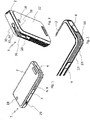
- Fig. 1 shows an electronic device 1 according to the present invention.
- the shown electronic device 1 is preferably a smartphone.
- the electronic device 1 comprises a housing 2, wherein electronic components are arranged inside said housing 2.
- a light source 18 or a camera 18 might be part of the housing 2.
- one or more buttons 20, in particularly for adjusting system parameters like loudness or camera, are present.
- the electronic device comprises as input means for inputting commands a touch screen only.
- Reference number 6 indicates a sliding means for repositioning of port 4.
- Port 4 is preferably a power jack. It is conceivable that sliding means 6 forms a sliding path 8 that extends only in one direction. In the shown example sliding path 8 extends into two directions. It is further conceivable that reference number 4 indicates multiple ports, in particularly for connecting multiple external devices at the same time, such a combined port or the individual ports are movable along the same sliding path 6.
- Fig. 2 shows a larger illustration of an electronic device 1 according to the present invention.
- the sliding means 6 comprise at least a first section 12 and a second section 14, wherein a port can be moved along both sections, since both sections 12, 14 are forming said sliding path 8.
- the second section 14 is preferably arranged along a lower end of the electronic device 1.
- Fig. 3 shows a further example of the present invention.
- Said sliding means 34 preferably comprises a first section 36 and a second section 38.
- the second section 38 preferably extends along the upper end of the electronic device 1 respectively housing 2.
- the first section 36 and the second section 38 are preferably connected to each other, in particularly forming the sliding path 34.
- Reference number 30 indicates physical port, in particularly a second physical port like a head phone jack.
- the electronic device 1 comprises the first sliding means 6 and the second sliding means 34 for modifying the position of a first physical port and a second port.
- the present invention discloses an electronic device 1, which comprises at least a housing 2, a processor unit arranged inside said housing 2, a physical port 4 for inputting electric energy for operating said processor unit and/or for outputting of acoustic signals or acoustic data, wherein the physical port 4 is coupled via a sliding means 6 to the housing 2, wherein the sliding means 6 provides a sliding path 8 for repositioning of the physical port 4 with respect to the housing 2.
Landscapes
- Engineering & Computer Science (AREA)
- Computer Hardware Design (AREA)
- General Engineering & Computer Science (AREA)
- Theoretical Computer Science (AREA)
- Human Computer Interaction (AREA)
- Physics & Mathematics (AREA)
- General Physics & Mathematics (AREA)
- Signal Processing (AREA)
- Telephone Set Structure (AREA)
- Casings For Electric Apparatus (AREA)
Abstract
Description
- The present invention refers according to
claim 1 to an electronic device. - Document
CN106208232A discloses a mobile power source which is portable and securely placed, and relates to the field of digital product accessories. The device according toCN106208232A includes a mobile power source, an end side interface, an annular side interface, a charging interface, an end side indicator lamp and an annular side indicator lamp. The end side interface is located on both ends of the mobile power source, and at least three of the ring side interfaces are arranged at the side of the mobile power source and the side indicator light are located on the upper side of the end side interface. The side indicator light is located on the upper side of the ring side interface. According toCN106208232A the respective indicator lights are installed on each external transmission interface of the mobile power supply. If the mobile phone charging cable connector is completely connected with the external power transmission interface of the mobile power supply, the indicator light will be bright and vice versa. The bottom side of the cylindrical mobile power supply is arranged in a flat structure, and the mobile power source can be firmly placed. - There are many types of charging or earphone (headset) jacks that are placed on cell phones, tablets, televisions, smart walls etc.. However, none of them supports further needs of the user.
- Thus, charging or headphone connector jacks are limited by a few designs for bottom and top part of the phone, respectively. Due to the classical and deep-seated designs, cell phone utilization while charging can be frustrating and this situation can be result with the cutting off the cable (or ports (jack box) can be unwind) in time.
- It is the object of the present invention to provide an electronic device with improved connector properties.
- The before mentioned object is solved by an electronic device according to
claim 1. The electronic device according to the present invention preferably comprises at least a housing, a processor unit arranged inside said housing, a physical port for inputting electric energy for operating said processor unit and/or for outputting of acoustic signals or acoustic data, wherein the physical port is coupled via a sliding means to the housing, wherein the sliding means provides a sliding path for repositioning of the physical port with respect to the housing. The processor unit is preferably a processor unit for operating a cell phone or smart phone or tablet PC or smart watch or e-book reader, etc. - This invention is beneficial since preferably at the bottom side of the phone, tablet, etc., a power jack is arranged which has moving ability to the margent side by using of the short line between the bottom and the margent. However, at the up side of the phone, tablet, etc., earphone jack has moving ability to the margent side by using of the short line between the up and the margent of the device.
- Thus, there is preferably a movable jack port for power and/or earphone of cellphone, tablet, TV, charge cable, connector, etc.
- Further preferred embodiments of the present invention are subject-matter of the specification parts and/or of the dependent claims.
- According to a preferred embodiment of the present invention a movable or flexible cover member is provided, wherein the cover member covers the sliding path. Said cover member preferably seals the housing to prevent access of dust and/or water into the inside of the housing. This embodiment is beneficial since due to the cover member the inside of the housing is protected respectively kept clean.
- The sliding path comprises according to a further preferred embodiment of the present invention at least a first section and a second section, wherein the first section and second section are connected to each other, wherein the physical port is slidable from the first section to the second section and/or from the second section to the first section, wherein the first section and the second section are inclined to each other, in particularly inclined in an angle between 10° and 170°, in particularly in an angle between 45° and 135°, in particularly in an angle between 80° and 100° or in an angle of 90°. This embodiment is beneficial since the port orientation can be changed without the need of changing the position of the electronic device. Thus, the electronic device is more flexible compared to know devices.
- A signal and/or energy connection for connecting the physical port with the processor unit, in particular a battery or acoustic data/signal processing means, is provided according to a further preferred embodiment of the present invention. The signal and/or energy connection is preferably part of the sliding means, wherein the physical port is electronically coupled with the signal and/or energy connection for exchanging signals and/or energy. The signal and/or energy connection is highly preferably arranged in a static, in particular printed, manner. This embodiment is beneficial since no cables are necessary for directly connecting the port and a battery or the port and an acoustic data/signal processing means.
- The sliding path extends according to a further preferred embodiment into the inside of the housing. Sliding directions of the physical port inside said housing are defining a siding plane, wherein the physical port extends into the sliding path inside the housing, wherein battery components, processor components and/or screen components are arranged on at least one side of the sliding path between the sliding plane and the housing, wherein the battery components, processor components and/or screen components are at least partially overlaying the sliding path.
- A detection means for detecting the position of the physical port is provided according to a further preferred embodiment of the present invention, wherein signals and/or data representing the position of the physical port is generated and outputted by the detection means in dependency of the actual position of the physical port. This embodiment is beneficial since features like screen orientation can be adapted in dependency of port orientation.
- According to a further embodiment of the present invention a lock mechanism is provided for locking the physical port in place. The locking mechanism preferably comprises an electronic actuator, wherein the electronic actuator is operated in dependency of software commands. This embodiment is beneficial since unintended sliding of one or multiple ports can be avoided.
- An electric motor for sliding the physical port along the sliding path is provided according to a further preferred embodiment of the present invention, wherein the electric motor is preferably operated via software executed on said electronic device. This embodiment is beneficial since it causes more comfort for the user.
- The electronic device is according to a further preferred embodiment of the present invention a smartphone, tablet PC, laptop, television, digital signage unit, e-book reader, videowall, Smart Board, smart watch, head-mounted display.
- A second physical port for inputting electric energy for operating said processor unit and/or for outputting of acoustic signals or acoustic data is provided according to a further preferred embodiment of the present invention, wherein the second physical port is coupled via a second sliding means to the housing, wherein the second sliding means provides a second sliding path for repositioning of the second physical port with respect to the housing. This embodiment is beneficial since multiple ports can be modified to better fit to user needs.
- According to a further preferred embodiment the physical port is a power jack and/or an ear phone jack.
- Further benefits, goals and features of the present invention will be described by the following specification of the attached figure, in which exemplarily components of the invention are illustrated. Components of the device and methods according to the invention, which match at least essentially with respect to their function can be marked with the same reference sign, wherein such components do not have to be marked or described multiple times with respect to said figure. In the following the invention is just exemplarily described with respect to the attached figure.
-
-
Fig. 1 shows exemplarily a first illustration of an electronic device according to the present invention, -
Fig. 2 shows a more detailed illustration of an example of a sliding path of a device according to the present invention, and -
Fig. 3 shows a further perspective of device shown infigures 1 and 2 . -
Fig. 1 shows anelectronic device 1 according to the present invention. The shownelectronic device 1 is preferably a smartphone. Theelectronic device 1 comprises ahousing 2, wherein electronic components are arranged inside saidhousing 2. Furthermore, alight source 18 or acamera 18 might be part of thehousing 2. It is further conceivable that one ormore buttons 20, in particularly for adjusting system parameters like loudness or camera, are present. However, it is also possible that the electronic device comprises as input means for inputting commands a touch screen only. - Reference number 6 indicates a sliding means for repositioning of
port 4.Port 4 is preferably a power jack. It is conceivable that sliding means 6 forms a sliding path 8 that extends only in one direction. In the shown example sliding path 8 extends into two directions. It is further conceivable thatreference number 4 indicates multiple ports, in particularly for connecting multiple external devices at the same time, such a combined port or the individual ports are movable along the same sliding path 6. -
Fig. 2 shows a larger illustration of anelectronic device 1 according to the present invention. The sliding means 6 comprise at least afirst section 12 and asecond section 14, wherein a port can be moved along both sections, since bothsections second section 14 is preferably arranged along a lower end of theelectronic device 1. -
Fig. 3 shows a further example of the present invention. According to this illustration an additional or alternative sliding means 6, 34 is provided. Said sliding means 34 preferably comprises afirst section 36 and asecond section 38. Thesecond section 38 preferably extends along the upper end of theelectronic device 1 respectivelyhousing 2. Thefirst section 36 and thesecond section 38 are preferably connected to each other, in particularly forming the sliding path 34.Reference number 30 indicates physical port, in particularly a second physical port like a head phone jack. - According to a preferred embodiment the
electronic device 1 comprises the first sliding means 6 and the second sliding means 34 for modifying the position of a first physical port and a second port. - Thus, the present invention discloses an
electronic device 1, which comprises at least ahousing 2, a processor unit arranged inside saidhousing 2, aphysical port 4 for inputting electric energy for operating said processor unit and/or for outputting of acoustic signals or acoustic data, wherein thephysical port 4 is coupled via a sliding means 6 to thehousing 2, wherein the sliding means 6 provides a sliding path 8 for repositioning of thephysical port 4 with respect to thehousing 2. -
- 1
- electronic device
- 2
- housing
- 4
- physical port
- 6
- sliding means
- 8
- sliding path
- 10
- cover member
- 12
- first section
- 14
- second section
- 16
- sliding plane
- 18
- camera / light
- 20
- button
- 22
- backside
- 30
- second physical port
- 32
- second sliding means
- 34
- second sliding path
- 36
- first section of second sliding path
- 38
- second section of second sliding path
Claims (14)
- Electronic device (1),
at least comprising
a housing (2),
a processor unit arranged inside said housing (2),
a physical port (4) for inputting electric energy for operating said processor unit and/or for outputting of acoustic signals or acoustic data,
wherein the physical port (4) is coupled via a sliding means (6) to the housing (2),
wherein the sliding means (6) provides a sliding path (8) for repositioning of the physical port (4) with respect to the housing (2). - Electronic device according to claim 1,
characterized in that
a movable or flexible cover member (10) is provided,
wherein the cover member (10) covers the sliding path (8). - Electronic device according to claim 1 or claim 2,
characterized in that
the sliding path (8) comprises at least a first section (12) and a second section (14), wherein the first section (12) and second section (14) are connected to each other, wherein the physical port (4) is slidable from the first section (12) to the second section (12) and/or from the second section (14) to the first section (12),
wherein the first section (12) and the second section (14) are inclined to each other, in particularly inclined in an angle of 90°. - Electronic device according to any of the proceeding claims,
characterized in that
a signal and/or energy connection for connecting the physical port (4) with the processor unit, in particular a battery or acoustic data/signal processing means, is provided, wherein the signal and/or energy connection is part of the sliding means (6), wherein the physical port (4) is electronically coupled with the signal and/or energy connection for exchanging signals and/or energy. - Electronic device according to claim 1,
characterized in that
the signal and/or energy connection is arranged in a static, in particular printed, manner. - Electronic device according to any of the proceeding claims,
characterized in that
the sliding path (8) extends into the inside of the housing (2),
wherein sliding directions of the physical port (4) inside said housing (2) are defining a siding plane (16),
wherein the physical port (4) extends into the sliding path (8) inside the housing (2),
wherein battery components, processor components and/or screen components are arranged on at least one side of the sliding path (8) between the sliding plane (16) and the housing, wherein the battery components, processor components and/or screen components are at least partially overlaying the sliding path (8). - Electronic device according to any of the proceeding claims,
characterized in that
a detection means for detecting the position of the physical port (4) is provided, wherein signals and/or data representing the position of the physical port is generated and outputted by the detection means in dependency of the actual position of the physical port (4). - Electronic device according to any of the proceeding claims,
characterized in that
a lock mechanism is provided for locking the physical port (4) in place. - Electronic device according to claim 1,
characterized in that
wherein the locking mechanism comprises an electronic actuator, wherein the electronic actuator is operated in dependency of software commands. - Electronic device according to any of the proceeding claims,
characterized in that
an electric motor for sliding the physical port (4) along the sliding path is provided, wherein the electric motor is preferably operated via software executed on said electronic device. - Electronic device according to any of the proceeding claims,
characterized in that
the electronic device is a smartphone, tablet PC, laptop, television, digital signage unit, e-book reader, videowall, Smart Board, smart watch, head-mounted display. - Electronic device according to any of the proceeding claims,
characterized in that
the physical port (4) is a power jack. - Electronic device according to any of the proceeding claims,
characterized in that
the physical port (4) is an ear phone jack. - Electronic device according to any of the proceeding claims,
characterized in that
a second physical port (30) for inputting electric energy for operating said processor unit and/or for outputting of acoustic signals or acoustic data is provided,
wherein the second physical port (30) is coupled via a second sliding means (32) to the housing (2),
wherein the second sliding means (32) provides a second sliding path (34) for repositioning of the second physical port (30) with respect to the housing (2).
Priority Applications (1)
| Application Number | Priority Date | Filing Date | Title |
|---|---|---|---|
| EP17165361.1A EP3386173B1 (en) | 2017-04-06 | 2017-04-06 | Electronic device with slidable connector port |
Applications Claiming Priority (1)
| Application Number | Priority Date | Filing Date | Title |
|---|---|---|---|
| EP17165361.1A EP3386173B1 (en) | 2017-04-06 | 2017-04-06 | Electronic device with slidable connector port |
Publications (2)
| Publication Number | Publication Date |
|---|---|
| EP3386173A1 true EP3386173A1 (en) | 2018-10-10 |
| EP3386173B1 EP3386173B1 (en) | 2020-01-08 |
Family
ID=58671339
Family Applications (1)
| Application Number | Title | Priority Date | Filing Date |
|---|---|---|---|
| EP17165361.1A Active EP3386173B1 (en) | 2017-04-06 | 2017-04-06 | Electronic device with slidable connector port |
Country Status (1)
| Country | Link |
|---|---|
| EP (1) | EP3386173B1 (en) |
Citations (4)
| Publication number | Priority date | Publication date | Assignee | Title |
|---|---|---|---|---|
| US6439900B1 (en) * | 2000-10-13 | 2002-08-27 | 3Com Corporation | Sliding connector interface with non-metallic contacts |
| EP2093979A1 (en) * | 2008-02-19 | 2009-08-26 | Research In Motion Limited | Multi-function slide mechanism for a mobile communication device |
| US20110228495A1 (en) * | 2010-03-16 | 2011-09-22 | Hong Fu Jin Precision Industry (Shenzhen) Co., Ltd . | Electronic device with multiple usb ports |
| CN106208232A (en) | 2016-08-17 | 2016-12-07 | 合肥召洋电子科技有限公司 | A kind of portable power source being easy to carry and consolidate placement |
-
2017
- 2017-04-06 EP EP17165361.1A patent/EP3386173B1/en active Active
Patent Citations (4)
| Publication number | Priority date | Publication date | Assignee | Title |
|---|---|---|---|---|
| US6439900B1 (en) * | 2000-10-13 | 2002-08-27 | 3Com Corporation | Sliding connector interface with non-metallic contacts |
| EP2093979A1 (en) * | 2008-02-19 | 2009-08-26 | Research In Motion Limited | Multi-function slide mechanism for a mobile communication device |
| US20110228495A1 (en) * | 2010-03-16 | 2011-09-22 | Hong Fu Jin Precision Industry (Shenzhen) Co., Ltd . | Electronic device with multiple usb ports |
| CN106208232A (en) | 2016-08-17 | 2016-12-07 | 合肥召洋电子科技有限公司 | A kind of portable power source being easy to carry and consolidate placement |
Also Published As
| Publication number | Publication date |
|---|---|
| EP3386173B1 (en) | 2020-01-08 |
Similar Documents
| Publication | Publication Date | Title |
|---|---|---|
| CN205809767U (en) | Tablet PC and accessory system | |
| EP3699724B1 (en) | Electronic device comprising flexible hinge | |
| EP2922149B1 (en) | Audio jack, electronic equipment and electronic system | |
| KR20150124710A (en) | Mobile terminal case and mobile terminal | |
| KR102196475B1 (en) | Detachable cover device | |
| US20130206803A1 (en) | Smartphone Holder | |
| KR102689437B1 (en) | Mobile terminal for setting home screen and method of controlling it | |
| US20140306919A1 (en) | Tablet device, information display method, display system, and display method | |
| KR20110113243A (en) | Mobile terminal | |
| KR20170137365A (en) | Mobile terminal | |
| KR20180010866A (en) | Mobile terminal | |
| KR20170088046A (en) | Circuit structure and mobile terminal | |
| KR20160016412A (en) | Mobile terminal case, mobile terminal and mobile terminal case's method for controlling the mobile terminal | |
| EP3386173B1 (en) | Electronic device with slidable connector port | |
| KR20160047180A (en) | Mobile terminal | |
| KR102639610B1 (en) | Mobile terminal, electronic device equipped with mobile terminal, and method of controlling the electronic device | |
| US11856120B2 (en) | Mobile terminal | |
| KR101580316B1 (en) | Input and output device for smartphone | |
| CN106101305A (en) | Electronic installation waterproof construction and waterproof mobile phone | |
| KR20170072724A (en) | A mobile terminal comprising a case and a manufacturing method thereof | |
| WO2019075451A2 (en) | System, method and apparatus for smart multiple devices | |
| US11509754B1 (en) | Mobile communication and gaming device | |
| US20160118205A1 (en) | Keyboard | |
| US11181943B2 (en) | Electronic device with self-aligning accessory | |
| KR20170017204A (en) | Connector and mobile terminal including the same |
Legal Events
| Date | Code | Title | Description |
|---|---|---|---|
| PUAI | Public reference made under article 153(3) epc to a published international application that has entered the european phase |
Free format text: ORIGINAL CODE: 0009012 |
|
| STAA | Information on the status of an ep patent application or granted ep patent |
Free format text: STATUS: THE APPLICATION HAS BEEN PUBLISHED |
|
| AK | Designated contracting states |
Kind code of ref document: A1 Designated state(s): AL AT BE BG CH CY CZ DE DK EE ES FI FR GB GR HR HU IE IS IT LI LT LU LV MC MK MT NL NO PL PT RO RS SE SI SK SM TR |
|
| AX | Request for extension of the european patent |
Extension state: BA ME |
|
| STAA | Information on the status of an ep patent application or granted ep patent |
Free format text: STATUS: REQUEST FOR EXAMINATION WAS MADE |
|
| 17P | Request for examination filed |
Effective date: 20190410 |
|
| RBV | Designated contracting states (corrected) |
Designated state(s): AL AT BE BG CH CY CZ DE DK EE ES FI FR GB GR HR HU IE IS IT LI LT LU LV MC MK MT NL NO PL PT RO RS SE SI SK SM TR |
|
| GRAP | Despatch of communication of intention to grant a patent |
Free format text: ORIGINAL CODE: EPIDOSNIGR1 |
|
| STAA | Information on the status of an ep patent application or granted ep patent |
Free format text: STATUS: GRANT OF PATENT IS INTENDED |
|
| INTG | Intention to grant announced |
Effective date: 20190730 |
|
| GRAS | Grant fee paid |
Free format text: ORIGINAL CODE: EPIDOSNIGR3 |
|
| GRAA | (expected) grant |
Free format text: ORIGINAL CODE: 0009210 |
|
| STAA | Information on the status of an ep patent application or granted ep patent |
Free format text: STATUS: THE PATENT HAS BEEN GRANTED |
|
| AK | Designated contracting states |
Kind code of ref document: B1 Designated state(s): AL AT BE BG CH CY CZ DE DK EE ES FI FR GB GR HR HU IE IS IT LI LT LU LV MC MK MT NL NO PL PT RO RS SE SI SK SM TR |
|
| REG | Reference to a national code |
Ref country code: GB Ref legal event code: FG4D |
|
| REG | Reference to a national code |
Ref country code: CH Ref legal event code: EP |
|
| REG | Reference to a national code |
Ref country code: IE Ref legal event code: FG4D |
|
| REG | Reference to a national code |
Ref country code: DE Ref legal event code: R096 Ref document number: 602017010541 Country of ref document: DE |
|
| REG | Reference to a national code |
Ref country code: AT Ref legal event code: REF Ref document number: 1224123 Country of ref document: AT Kind code of ref document: T Effective date: 20200215 |
|
| REG | Reference to a national code |
Ref country code: NL Ref legal event code: MP Effective date: 20200108 |
|
| REG | Reference to a national code |
Ref country code: LT Ref legal event code: MG4D |
|
| PG25 | Lapsed in a contracting state [announced via postgrant information from national office to epo] |
Ref country code: FI Free format text: LAPSE BECAUSE OF FAILURE TO SUBMIT A TRANSLATION OF THE DESCRIPTION OR TO PAY THE FEE WITHIN THE PRESCRIBED TIME-LIMIT Effective date: 20200108 Ref country code: NO Free format text: LAPSE BECAUSE OF FAILURE TO SUBMIT A TRANSLATION OF THE DESCRIPTION OR TO PAY THE FEE WITHIN THE PRESCRIBED TIME-LIMIT Effective date: 20200408 Ref country code: PT Free format text: LAPSE BECAUSE OF FAILURE TO SUBMIT A TRANSLATION OF THE DESCRIPTION OR TO PAY THE FEE WITHIN THE PRESCRIBED TIME-LIMIT Effective date: 20200531 Ref country code: RS Free format text: LAPSE BECAUSE OF FAILURE TO SUBMIT A TRANSLATION OF THE DESCRIPTION OR TO PAY THE FEE WITHIN THE PRESCRIBED TIME-LIMIT Effective date: 20200108 Ref country code: LT Free format text: LAPSE BECAUSE OF FAILURE TO SUBMIT A TRANSLATION OF THE DESCRIPTION OR TO PAY THE FEE WITHIN THE PRESCRIBED TIME-LIMIT Effective date: 20200108 Ref country code: NL Free format text: LAPSE BECAUSE OF FAILURE TO SUBMIT A TRANSLATION OF THE DESCRIPTION OR TO PAY THE FEE WITHIN THE PRESCRIBED TIME-LIMIT Effective date: 20200108 |
|
| PGFP | Annual fee paid to national office [announced via postgrant information from national office to epo] |
Ref country code: DE Payment date: 20200525 Year of fee payment: 4 |
|
| PG25 | Lapsed in a contracting state [announced via postgrant information from national office to epo] |
Ref country code: GR Free format text: LAPSE BECAUSE OF FAILURE TO SUBMIT A TRANSLATION OF THE DESCRIPTION OR TO PAY THE FEE WITHIN THE PRESCRIBED TIME-LIMIT Effective date: 20200409 Ref country code: BG Free format text: LAPSE BECAUSE OF FAILURE TO SUBMIT A TRANSLATION OF THE DESCRIPTION OR TO PAY THE FEE WITHIN THE PRESCRIBED TIME-LIMIT Effective date: 20200408 Ref country code: HR Free format text: LAPSE BECAUSE OF FAILURE TO SUBMIT A TRANSLATION OF THE DESCRIPTION OR TO PAY THE FEE WITHIN THE PRESCRIBED TIME-LIMIT Effective date: 20200108 Ref country code: SE Free format text: LAPSE BECAUSE OF FAILURE TO SUBMIT A TRANSLATION OF THE DESCRIPTION OR TO PAY THE FEE WITHIN THE PRESCRIBED TIME-LIMIT Effective date: 20200108 Ref country code: IS Free format text: LAPSE BECAUSE OF FAILURE TO SUBMIT A TRANSLATION OF THE DESCRIPTION OR TO PAY THE FEE WITHIN THE PRESCRIBED TIME-LIMIT Effective date: 20200508 Ref country code: LV Free format text: LAPSE BECAUSE OF FAILURE TO SUBMIT A TRANSLATION OF THE DESCRIPTION OR TO PAY THE FEE WITHIN THE PRESCRIBED TIME-LIMIT Effective date: 20200108 |
|
| REG | Reference to a national code |
Ref country code: DE Ref legal event code: R097 Ref document number: 602017010541 Country of ref document: DE |
|
| PG25 | Lapsed in a contracting state [announced via postgrant information from national office to epo] |
Ref country code: ES Free format text: LAPSE BECAUSE OF FAILURE TO SUBMIT A TRANSLATION OF THE DESCRIPTION OR TO PAY THE FEE WITHIN THE PRESCRIBED TIME-LIMIT Effective date: 20200108 Ref country code: CZ Free format text: LAPSE BECAUSE OF FAILURE TO SUBMIT A TRANSLATION OF THE DESCRIPTION OR TO PAY THE FEE WITHIN THE PRESCRIBED TIME-LIMIT Effective date: 20200108 Ref country code: RO Free format text: LAPSE BECAUSE OF FAILURE TO SUBMIT A TRANSLATION OF THE DESCRIPTION OR TO PAY THE FEE WITHIN THE PRESCRIBED TIME-LIMIT Effective date: 20200108 Ref country code: SM Free format text: LAPSE BECAUSE OF FAILURE TO SUBMIT A TRANSLATION OF THE DESCRIPTION OR TO PAY THE FEE WITHIN THE PRESCRIBED TIME-LIMIT Effective date: 20200108 Ref country code: EE Free format text: LAPSE BECAUSE OF FAILURE TO SUBMIT A TRANSLATION OF THE DESCRIPTION OR TO PAY THE FEE WITHIN THE PRESCRIBED TIME-LIMIT Effective date: 20200108 Ref country code: SK Free format text: LAPSE BECAUSE OF FAILURE TO SUBMIT A TRANSLATION OF THE DESCRIPTION OR TO PAY THE FEE WITHIN THE PRESCRIBED TIME-LIMIT Effective date: 20200108 Ref country code: DK Free format text: LAPSE BECAUSE OF FAILURE TO SUBMIT A TRANSLATION OF THE DESCRIPTION OR TO PAY THE FEE WITHIN THE PRESCRIBED TIME-LIMIT Effective date: 20200108 |
|
| PLBE | No opposition filed within time limit |
Free format text: ORIGINAL CODE: 0009261 |
|
| STAA | Information on the status of an ep patent application or granted ep patent |
Free format text: STATUS: NO OPPOSITION FILED WITHIN TIME LIMIT |
|
| REG | Reference to a national code |
Ref country code: AT Ref legal event code: MK05 Ref document number: 1224123 Country of ref document: AT Kind code of ref document: T Effective date: 20200108 |
|
| PG25 | Lapsed in a contracting state [announced via postgrant information from national office to epo] |
Ref country code: MC Free format text: LAPSE BECAUSE OF FAILURE TO SUBMIT A TRANSLATION OF THE DESCRIPTION OR TO PAY THE FEE WITHIN THE PRESCRIBED TIME-LIMIT Effective date: 20200108 |
|
| REG | Reference to a national code |
Ref country code: CH Ref legal event code: PL |
|
| 26N | No opposition filed |
Effective date: 20201009 |
|
| PG25 | Lapsed in a contracting state [announced via postgrant information from national office to epo] |
Ref country code: FR Free format text: LAPSE BECAUSE OF NON-PAYMENT OF DUE FEES Effective date: 20200430 Ref country code: LU Free format text: LAPSE BECAUSE OF NON-PAYMENT OF DUE FEES Effective date: 20200406 Ref country code: LI Free format text: LAPSE BECAUSE OF NON-PAYMENT OF DUE FEES Effective date: 20200430 Ref country code: CH Free format text: LAPSE BECAUSE OF NON-PAYMENT OF DUE FEES Effective date: 20200430 Ref country code: IT Free format text: LAPSE BECAUSE OF FAILURE TO SUBMIT A TRANSLATION OF THE DESCRIPTION OR TO PAY THE FEE WITHIN THE PRESCRIBED TIME-LIMIT Effective date: 20200108 Ref country code: AT Free format text: LAPSE BECAUSE OF FAILURE TO SUBMIT A TRANSLATION OF THE DESCRIPTION OR TO PAY THE FEE WITHIN THE PRESCRIBED TIME-LIMIT Effective date: 20200108 |
|
| REG | Reference to a national code |
Ref country code: BE Ref legal event code: MM Effective date: 20200430 |
|
| PG25 | Lapsed in a contracting state [announced via postgrant information from national office to epo] |
Ref country code: PL Free format text: LAPSE BECAUSE OF FAILURE TO SUBMIT A TRANSLATION OF THE DESCRIPTION OR TO PAY THE FEE WITHIN THE PRESCRIBED TIME-LIMIT Effective date: 20200108 Ref country code: BE Free format text: LAPSE BECAUSE OF NON-PAYMENT OF DUE FEES Effective date: 20200430 Ref country code: SI Free format text: LAPSE BECAUSE OF FAILURE TO SUBMIT A TRANSLATION OF THE DESCRIPTION OR TO PAY THE FEE WITHIN THE PRESCRIBED TIME-LIMIT Effective date: 20200108 |
|
| PG25 | Lapsed in a contracting state [announced via postgrant information from national office to epo] |
Ref country code: IE Free format text: LAPSE BECAUSE OF NON-PAYMENT OF DUE FEES Effective date: 20200406 |
|
| REG | Reference to a national code |
Ref country code: DE Ref legal event code: R119 Ref document number: 602017010541 Country of ref document: DE |
|
| GBPC | Gb: european patent ceased through non-payment of renewal fee |
Effective date: 20210406 |
|
| PG25 | Lapsed in a contracting state [announced via postgrant information from national office to epo] |
Ref country code: GB Free format text: LAPSE BECAUSE OF NON-PAYMENT OF DUE FEES Effective date: 20210406 Ref country code: DE Free format text: LAPSE BECAUSE OF NON-PAYMENT OF DUE FEES Effective date: 20211103 |
|
| PG25 | Lapsed in a contracting state [announced via postgrant information from national office to epo] |
Ref country code: MT Free format text: LAPSE BECAUSE OF FAILURE TO SUBMIT A TRANSLATION OF THE DESCRIPTION OR TO PAY THE FEE WITHIN THE PRESCRIBED TIME-LIMIT Effective date: 20200108 Ref country code: CY Free format text: LAPSE BECAUSE OF FAILURE TO SUBMIT A TRANSLATION OF THE DESCRIPTION OR TO PAY THE FEE WITHIN THE PRESCRIBED TIME-LIMIT Effective date: 20200108 |
|
| PG25 | Lapsed in a contracting state [announced via postgrant information from national office to epo] |
Ref country code: MK Free format text: LAPSE BECAUSE OF FAILURE TO SUBMIT A TRANSLATION OF THE DESCRIPTION OR TO PAY THE FEE WITHIN THE PRESCRIBED TIME-LIMIT Effective date: 20200108 Ref country code: AL Free format text: LAPSE BECAUSE OF FAILURE TO SUBMIT A TRANSLATION OF THE DESCRIPTION OR TO PAY THE FEE WITHIN THE PRESCRIBED TIME-LIMIT Effective date: 20200108 |
|
| PGFP | Annual fee paid to national office [announced via postgrant information from national office to epo] |
Ref country code: TR Payment date: 20250403 Year of fee payment: 9 |