EP3386154A1 - Method for connecting a household appliance to a wireless home network - Google Patents
Method for connecting a household appliance to a wireless home network Download PDFInfo
- Publication number
- EP3386154A1 EP3386154A1 EP18163297.7A EP18163297A EP3386154A1 EP 3386154 A1 EP3386154 A1 EP 3386154A1 EP 18163297 A EP18163297 A EP 18163297A EP 3386154 A1 EP3386154 A1 EP 3386154A1
- Authority
- EP
- European Patent Office
- Prior art keywords
- network
- household appliance
- hotspot identification
- hotspot
- user terminal
- Prior art date
- Legal status (The legal status is an assumption and is not a legal conclusion. Google has not performed a legal analysis and makes no representation as to the accuracy of the status listed.)
- Granted
Links
Images

Classifications
-
- H—ELECTRICITY
- H04—ELECTRIC COMMUNICATION TECHNIQUE
- H04W—WIRELESS COMMUNICATION NETWORKS
- H04W12/00—Security arrangements; Authentication; Protecting privacy or anonymity
- H04W12/08—Access security
-
- H—ELECTRICITY
- H04—ELECTRIC COMMUNICATION TECHNIQUE
- H04L—TRANSMISSION OF DIGITAL INFORMATION, e.g. TELEGRAPHIC COMMUNICATION
- H04L12/00—Data switching networks
- H04L12/28—Data switching networks characterised by path configuration, e.g. LAN [Local Area Networks] or WAN [Wide Area Networks]
- H04L12/2803—Home automation networks
- H04L12/2807—Exchanging configuration information on appliance services in a home automation network
-
- G—PHYSICS
- G06—COMPUTING; CALCULATING OR COUNTING
- G06K—GRAPHICAL DATA READING; PRESENTATION OF DATA; RECORD CARRIERS; HANDLING RECORD CARRIERS
- G06K7/00—Methods or arrangements for sensing record carriers, e.g. for reading patterns
- G06K7/10—Methods or arrangements for sensing record carriers, e.g. for reading patterns by electromagnetic radiation, e.g. optical sensing; by corpuscular radiation
- G06K7/10544—Methods or arrangements for sensing record carriers, e.g. for reading patterns by electromagnetic radiation, e.g. optical sensing; by corpuscular radiation by scanning of the records by radiation in the optical part of the electromagnetic spectrum
- G06K7/10821—Methods or arrangements for sensing record carriers, e.g. for reading patterns by electromagnetic radiation, e.g. optical sensing; by corpuscular radiation by scanning of the records by radiation in the optical part of the electromagnetic spectrum further details of bar or optical code scanning devices
- G06K7/1095—Methods or arrangements for sensing record carriers, e.g. for reading patterns by electromagnetic radiation, e.g. optical sensing; by corpuscular radiation by scanning of the records by radiation in the optical part of the electromagnetic spectrum further details of bar or optical code scanning devices the scanner comprising adaptations for scanning a record carrier that is displayed on a display-screen or the like
-
- H—ELECTRICITY
- H04—ELECTRIC COMMUNICATION TECHNIQUE
- H04L—TRANSMISSION OF DIGITAL INFORMATION, e.g. TELEGRAPHIC COMMUNICATION
- H04L12/00—Data switching networks
- H04L12/28—Data switching networks characterised by path configuration, e.g. LAN [Local Area Networks] or WAN [Wide Area Networks]
- H04L12/2854—Wide area networks, e.g. public data networks
- H04L12/2856—Access arrangements, e.g. Internet access
- H04L12/2858—Access network architectures
- H04L12/2859—Point-to-point connection between the data network and the subscribers
-
- H—ELECTRICITY
- H04—ELECTRIC COMMUNICATION TECHNIQUE
- H04L—TRANSMISSION OF DIGITAL INFORMATION, e.g. TELEGRAPHIC COMMUNICATION
- H04L12/00—Data switching networks
- H04L12/28—Data switching networks characterised by path configuration, e.g. LAN [Local Area Networks] or WAN [Wide Area Networks]
- H04L12/2854—Wide area networks, e.g. public data networks
- H04L12/2856—Access arrangements, e.g. Internet access
- H04L12/2869—Operational details of access network equipments
- H04L12/287—Remote access server, e.g. BRAS
- H04L12/2876—Handling of subscriber policies
-
- H—ELECTRICITY
- H04—ELECTRIC COMMUNICATION TECHNIQUE
- H04L—TRANSMISSION OF DIGITAL INFORMATION, e.g. TELEGRAPHIC COMMUNICATION
- H04L63/00—Network architectures or network communication protocols for network security
- H04L63/18—Network architectures or network communication protocols for network security using different networks or channels, e.g. using out of band channels
-
- H—ELECTRICITY
- H04—ELECTRIC COMMUNICATION TECHNIQUE
- H04W—WIRELESS COMMUNICATION NETWORKS
- H04W76/00—Connection management
- H04W76/10—Connection setup
- H04W76/11—Allocation or use of connection identifiers
-
- H—ELECTRICITY
- H04—ELECTRIC COMMUNICATION TECHNIQUE
- H04L—TRANSMISSION OF DIGITAL INFORMATION, e.g. TELEGRAPHIC COMMUNICATION
- H04L12/00—Data switching networks
- H04L12/28—Data switching networks characterised by path configuration, e.g. LAN [Local Area Networks] or WAN [Wide Area Networks]
- H04L12/2803—Home automation networks
- H04L2012/284—Home automation networks characterised by the type of medium used
- H04L2012/2841—Wireless
-
- H—ELECTRICITY
- H04—ELECTRIC COMMUNICATION TECHNIQUE
- H04L—TRANSMISSION OF DIGITAL INFORMATION, e.g. TELEGRAPHIC COMMUNICATION
- H04L12/00—Data switching networks
- H04L12/28—Data switching networks characterised by path configuration, e.g. LAN [Local Area Networks] or WAN [Wide Area Networks]
- H04L12/2803—Home automation networks
- H04L2012/2847—Home automation networks characterised by the type of home appliance used
-
- H—ELECTRICITY
- H04—ELECTRIC COMMUNICATION TECHNIQUE
- H04L—TRANSMISSION OF DIGITAL INFORMATION, e.g. TELEGRAPHIC COMMUNICATION
- H04L41/00—Arrangements for maintenance, administration or management of data switching networks, e.g. of packet switching networks
- H04L41/08—Configuration management of networks or network elements
- H04L41/0803—Configuration setting
- H04L41/0806—Configuration setting for initial configuration or provisioning, e.g. plug-and-play
Definitions
- the invention relates to a method for connecting a household appliance with a wireless home network, wherein the household appliance provides a temporary network with a hotspot identification, wherein a user terminal is connected using the hotspot identification via the temporary network with the household appliance, wherein the User terminal transmitted network access information to the household appliance, and wherein the home appliance after receipt of the network access information closes the temporary network and logs on the home network using the received network access information.
- the invention relates to a household appliance with a hotspot device for providing a temporary network and with a device for providing a hotspot identification for access to the temporary network.
- the patent EP 1 309 127 B1 discloses, for example, a method of connecting a device to an existing wireless network to which a plurality of communication devices are connected.
- the communication devices have the same identification for communication.
- the new device to be connected to the network has a memory in which a switching identification for a temporary wireless network is stored in advance. Based on this switch identification, the device establishes a temporary wireless network to which a communication device, already subscribing to the existing wireless network, can connect to provide network access information to the newly connected device for the existing wireless network.
- the device to be connected stores the network access information, closes the temporary wireless network, and connects to the existing wireless network using the obtained network access information.
- the invention proposes that the hotspot identification of the temporary network is randomly generated by means of a random character generator.
- the hotspot identification for the temporary network is no longer stored in a memory of the household appliance, or in a label on a housing of the household appliance, but is generated up-to-date and individually as needed.
- a different hotspot identification is generated for each case of the establishment of a temporary network, which serves for the connection of a user terminal with the temporary network of the household appliance. That's it on the one hand it is possible to allocate the hotspot identification used to a specific issue time and also to restrict the access authorization to the temporary network.
- the hotspot identification is only available during or shortly before the establishment of the temporary network and is not, as is common in the prior art, visible to anyone on either the household appliance itself or in a technical manual of the household appliance.
- the random character generator generates a sequence of random characters which are extracted from a particular area.
- two different types of random character generators can be distinguished, namely, on the one hand, the deterministic random character generators and the non-deterministic random character generators.
- Non-deterministic is a random character generator which generates different random characters under the same initial conditions. For this purpose, the generation of the random character is made dependent on an external, non-deterministic parameter, for example pulse fluctuations of an electronic circuit of the household appliance or the like.
- a deterministic random-character generator always delivers the same sequence of characters selected from a defined quantity under the same initial conditions. Both types of random character generators can be used in the method according to the invention.
- the random character generator generates the hotspot identification in time immediately before the construction of the temporary network or at the moment of the construction of the temporary network.
- the hotspot identification is thus generated exactly at the moment in which the temporary network is to be established or set up.
- the hotspot identification is also available available, which requires a user terminal to transmit the network access information to the household appliance. Storage of the hotspot identification in advance is therefore not required.
- the hotspot identification is rather existing only in the moment in which it is needed. It is possible to send out the same hotspot identification several times during the existence of the temporary network. Alternatively, it is possible that in each case a new hotspot identification is generated at certain time intervals. Especially in the latter case, no storage of the hotspot identification is required even after the construction of the temporary network.
- the hotspot identification be generated as a sequence of randomly selected numbers and / or letters and / or special characters.
- the hotspot identification thus has a plurality of characters, which may be digits, letters and / or special characters. Particularly advantageous is a number-letter combination chosen.
- the number of characters of the hotspot identification is basically not limited.
- the hotspot identification can thus be selected from at least one character to a sequence of ten, twenty or even more characters. The security of the hotspot identification increases with increasing number of characters.
- the hotspot identification can be displayed as a two-dimensional code on a display of the household appliance.
- the two-dimensional code is a QR code® (Quick Response Code).
- the optical code has a pattern, for example a black-and-white pattern, in which the hotspot identification is encoded.
- Such an optical code can For example, it may also be a barcode, a QR code, or some other sample code.
- the household appliance has a computing device, for example a QR code generator, which can transform a multi-character hotspot identification into an optical code.
- the optical code is received by means of an image sensor of the user terminal.
- the image sensor of the user terminal may, for example, be a camera or at least a camera chip.
- the user terminal is, for example, a mobile phone, a tablet computer or a laptop of the user, this user terminal usually already has an image sensor.
- the optical code is processed by means of an application installed on the user terminal and the hotspot identification is read from the optical code.
- the optical code received by the image sensor of the user terminal is further processed by means of the application installed on the user terminal such that the hotspot identification is available in a form which enables the user terminal to connect to the temporary network of the household appliance.
- the hotspot identification becomes invalid at the latest at the time of termination of the temporary network.
- the usability of the hotspot identification output from the random character generator is limited in time.
- the validity of the hotspot identification may be limited to a few minutes after the issue. A hotspot identification transmitted to the household appliance after its expiry date is ignored, so that a Access to the temporary network or a transmission of network access information to the home appliance is no longer possible, even if a temporary network is opened again.
- the invention also proposes a household appliance with a hotspot device for providing a temporary network and with a device for providing a hotspot identification for access to the temporary network wherein the means for providing the hotspot identification comprises a random character generator configured to generate the hotspot identification from randomly selected numbers and / or letters and / or special characters.
- the household appliance is thus designed according to the invention to carry out a method of the type described above in order to provide network access information to a household appliance which itself does not have a user interface for manual input of network access information.
- the hotspot device for providing a temporary network is preferably a network module, for example a WLAN module, which can take over the function of an access point.
- the device for providing the hotspot identification according to the invention has a random character generator which generates the hotspot identification at random.
- the household appliance has a display for displaying a two-dimensional optical code containing the hotspot identification.
- the two-dimensional optical code may in particular be a QR code.
- the household appliance may be a soil cultivating device, for example a cleaning device.
- the household appliance can be designed either as a user-controlled household appliance or as a self-propelled domestic appliance, in particular as a robot.
- the invention is also applicable to other household appliances, such as polishing, grinding, over-floor cleaning equipment, mowers, kitchen appliances, other service equipment, entertainment equipment or the like.
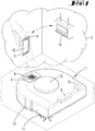
- FIG. 1 shows a home network 2, here for example a standard WiFi network, with an access point 14 and a user terminal 5. Furthermore, the FIG. 1 a household appliance 1, which, however, is not a participant of the home network 2.
- the household appliance 1, the user terminal 5 and the Access point 14 have WiFi radio modules for communication.
- the household appliance 1 here is a self-cleaning device, namely a vacuum cleaner.
- the user terminal 5 is a smartphone.
- the household appliance 1 has a navigation and self-locating device, not shown, by means of which the household appliance 1 can orient itself within an environment and move on.
- the navigation and self-locating device evaluates measurement data of a distance measuring device 12, which here is, for example, an all-round laser scanner in the manner of a laser triangulation measuring system.
- a distance measuring device 12 By means of the distance measuring device 12, distances to obstacles and room boundaries are measured.
- These measurement data are preferably compared with measurement data of an odometry sensor which detects a distance traveled by the household appliance 1.
- the information about obstacles and space limitations of the environment are further processed to a map of the household appliance 1, with the help of which the household appliance 1 can orient in the environment.
- the domestic appliance 1 has a cleaning element 11 for processing a surface to be cleaned.
- the cleaning element 11 is here, for example, an electric motor driven bristle roller.
- the household appliance 1 has wheels 13, which are motor-driven and serve to move the household appliance 1 within the environment.
- a display 8 is further arranged, on which various information can be displayed.
- the user terminal 5 has a display 15 and an image sensor 9, namely a camera.
- the display 15 is preferably a touch screen which serves to display various information and key areas. The key areas can be actuated by pressure.
- an application for communication and cooperation with the home appliance 1 is installed on the user terminal 5.
- FIG. 1 illustrated situation shows a time at which the household appliance 1 is not yet participants of the home network 2.
- the household appliance 1 requires network access information 16 for the access point 14.
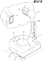
- the household appliance 1 opens a temporary network 3, with which the user terminal 5 can connect. This situation is in FIG. 2 shown.
- FIG. 2 shows the temporary network 3 of the household appliance 1 with a user terminal 5.
- a hotspot device 10 of the household appliance 1 for example, a network module with an access point function opens the temporary network 3 with a hotspot identification 4, which generates by means of a random character generator 6 becomes.
- This hotspot identification 4 is considered to be the SSID of the temporary network 3.
- the random character generator 6 generates the hotspot identification 4 from randomly selected characters, which here form, for example, a random sequence of letters and numbers, namely here, for example, the hotspot identification 4 "XY123" ,
- a computing device of the household appliance 1 then transforms the hotspot identification 4 into an optical code 7, here a QR code which contains the hotspot identification 4 in coded form.
- the optical code 7 is displayed on the display 8 of the household appliance 1.
- the application installed on the user terminal 5 is opened and controls the image sensor 9.
- the image sensor 9 detects the optical code 7 and forwards it to a computing device of the user terminal 5, which extracts the hotspot identification 4 from the optical code 7.
- the user terminal 5 can now log on to the temporary network 3 of the household appliance 1.
- the user terminal 5 subsequently transmits network access information 16 to the household appliance 1 via the temporary network 3.
- the hotspot information 4 and the network access information 16 are transmitted by means of the WiFi radio modules of the user terminal 5 and the household appliance 1.
- the network access information 16 is here, for example String "Access Point ABC ##". This serves to register the household appliance 1 on the home network 2.
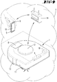
- the hotspot device 10 closes the temporary network 3. Then the home appliance 1 logs in as in FIG. 3 displayed on the home network 2. In detail, the household appliance 1 transmits the previously obtained network access information 16 "Access Point ABC ##" to the access point 14 of the home network 2. The access point 14 checks whether the network access information 16 is correct and takes the household appliance 1 in accordance as a participant in the home network 2 on.
- FIG. 4 shows the home network 2 after receiving the household appliance 1 as a participant.
- this home network 2 both the access point 14 and the user terminal 5 communicate with one another, as well as the access point 14 and the household appliance 1.
Abstract
Die Erfindung betrifft ein Verfahren zum Verbinden eines Haushaltsgerätes (1) mit einem drahtlosen Heimnetzwerk (2), wobei das Haushaltsgerät (1) ein temporäres Netzwerk (3) mit einer Hotspot-Identifikation (4) zur Verfügung stellt, wobei ein Nutzerendgerät (5) unter Nutzung der Hotspot-Identifikation (4) über das temporäre Netzwerk (3) mit dem Haushaltsgerät (1) verbunden wird, wobei das Nutzerendgerät (5) Netzwerkzugangsinformationen (16) an das Haushaltsgerät (1) übermittelt, und wobei das Haushaltsgerät (1) nach Empfang der Netzwerkzugangsinformationen (16) das temporäre Netzwerk (3) schließt und sich unter Nutzung der empfangenen Netzwerkzugangsinformationen (16) an dem Heimnetzwerk (2) anmeldet. Als Weiterbildung für die im Stand der Technik bekannten Verfahren, wird vorgeschlagen, dass die Hotspot-Identifikation (4) des temporären Netzwerkes (3) zufällig mittels eines Zufallszeichengenerators (6) generiert wird.

Description
Die Erfindung betrifft ein Verfahren zum Verbinden eines Haushaltsgerätes mit einem drahtlosen Heimnetzwerk, wobei das Haushaltsgerät ein temporäres Netzwerk mit einer Hotspot-Identifikation zur Verfügung stellt, wobei ein Nutzerendgerät unter Nutzung der Hotspot-Identifikation über das temporäre Netzwerk mit dem Haushaltsgerät verbunden wird, wobei das Nutzerendgerät Netzwerkzugangsinformationen an das Haushaltsgerät übermittelt, und wobei das Haushaltsgerät nach Empfang der Netzwerkzugangsinformationen das temporäre Netzwerk schließt und sich unter Nutzung der empfangenen Netzwerkzugangsinformationen an dem Heimnetzwerk anmeldet.The invention relates to a method for connecting a household appliance with a wireless home network, wherein the household appliance provides a temporary network with a hotspot identification, wherein a user terminal is connected using the hotspot identification via the temporary network with the household appliance, wherein the User terminal transmitted network access information to the household appliance, and wherein the home appliance after receipt of the network access information closes the temporary network and logs on the home network using the received network access information.
Darüber hinaus betrifft die Erfindung ein Haushaltsgerät mit einer Hotspot-Einrichtung zum Bereitstellen eines temporären Netzwerkes und mit einer Einrichtung zum Bereitstellen einer Hotspot-Identifikation für einen Zugang zu dem temporären Netzwerk.Moreover, the invention relates to a household appliance with a hotspot device for providing a temporary network and with a device for providing a hotspot identification for access to the temporary network.
Verfahren und Haushaltsgeräte der vorgenannten Art sind im Stand der Technik bekannt.Methods and household appliances of the aforementioned type are known in the art.
Die Patentschrift
Ausgehend von dem vorgenannten Stand der Technik ist es Aufgabe der Erfindung, ein alternatives Verfahren zum Verbinden eines Haushaltsgerätes mit einem drahtlosen Heimnetzwerk zu schaffen, bei welchem die Hotspot-Identifikation nicht im Voraus innerhalb des Haushaltsgerätes gespeichert sein muss.Based on the aforementioned prior art, it is an object of the invention to provide an alternative method for connecting a household appliance to a home wireless network, in which the hotspot identification does not have to be stored in advance within the household appliance.
Zur Lösung der vorgenannten Aufgabe wird mit der Erfindung vorgeschlagen, dass die Hotspot-Identifikation des temporären Netzwerkes zufällig mittels eines Zufallszeichengenerators generiert wird.To solve the above object, the invention proposes that the hotspot identification of the temporary network is randomly generated by means of a random character generator.
Entgegen dem Stand der Technik ist die Hotspot-Identifikation für das temporäre Netzwerk nun nicht mehr in einem Speicher des Haushaltsgerätes, oder in einem Label auf einem Gehäuse des Haushaltsgerätes, hinterlegt, sondern wird bei Bedarf aktuell und individuell generiert. Somit wird für jeden Fall der Errichtung eines temporären Netzwerkes eine andere Hotspot-Identifikation generiert, welche zur Verbindung eines Nutzerendgerätes mit dem temporären Netzwerk des Haushaltsgerätes dient. Dadurch ist es einerseits möglich, die verwendete Hotspot-Identifikation einem bestimmten Ausgabezeitpunkt zuzuordnen und andererseits auch, die Zugangsberechtigung zu dem temporären Netzwerk zu beschränken. Darüber hinaus ist die Hotspot-Identifikation nur während bzw. kurz vor dem Errichten des temporären Netzwerks verfügbar und befindet sich nicht, wie beispielsweise im Stand der Technik üblich, für jedermann sichtbar auf entweder dem Haushaltsgerät selbst oder in einer technischen Anleitung des Haushaltsgerätes. Dies schützt nicht zuletzt auch vor einem unbefugten Zugriff auf das temporäre Netzwerk des Haushaltsgerätes. Der Zufallszeichengenerator erzeugt eine Folge von Zufallszeichen, welche aus einem bestimmten Bereich entnommen werden. Grundsätzlich können zwei unterschiedliche Arten von Zufallszeichengeneratoren unterschieden werden, nämlich einerseits die deterministischen Zufallszeichengeneratoren und die nicht-deterministischen Zufallszeichengeneratoren. Nicht-deterministisch ist ein Zufallszeichengenerator, welcher bei gleichen Ausgangsbedingungen unterschiedliche Zufallszeichen generiert. Zu diesem Zweck wird die Generierung des Zufallszeichens beispielsweise von einem äußeren, nicht-deterministischen Parameter abhängig gemacht, beispielsweise von Impulsschwankungen einer elektronischen Schaltung des Haushaltsgerätes oder dergleichen. Ein deterministischer Zufallszeichengenerator liefert hingegen bei gleichen Ausgangsbedingungen eine immer gleiche Abfolge von Zeichen, die aus einer definierten Menge ausgewählt sind. Beide Arten von Zufallszeichengeneratoren können bei dem erfindungsgemäßen Verfahren Einsatz finden.Contrary to the prior art, the hotspot identification for the temporary network is no longer stored in a memory of the household appliance, or in a label on a housing of the household appliance, but is generated up-to-date and individually as needed. Thus, a different hotspot identification is generated for each case of the establishment of a temporary network, which serves for the connection of a user terminal with the temporary network of the household appliance. That's it on the one hand it is possible to allocate the hotspot identification used to a specific issue time and also to restrict the access authorization to the temporary network. In addition, the hotspot identification is only available during or shortly before the establishment of the temporary network and is not, as is common in the prior art, visible to anyone on either the household appliance itself or in a technical manual of the household appliance. This not least protects against unauthorized access to the temporary network of the household appliance. The random character generator generates a sequence of random characters which are extracted from a particular area. In principle, two different types of random character generators can be distinguished, namely, on the one hand, the deterministic random character generators and the non-deterministic random character generators. Non-deterministic is a random character generator which generates different random characters under the same initial conditions. For this purpose, the generation of the random character is made dependent on an external, non-deterministic parameter, for example pulse fluctuations of an electronic circuit of the household appliance or the like. On the other hand, a deterministic random-character generator always delivers the same sequence of characters selected from a defined quantity under the same initial conditions. Both types of random character generators can be used in the method according to the invention.
Es wird vorgeschlagen, dass der Zufallszeichengenerator die Hotspot-Identifikation zeitlich unmittelbar vor dem Aufbau des temporären Netzwerkes oder im Moment des Aufbaus des temporären Netzwerkes generiert. Die Hotspot-Identifikation wird somit genau in dem Moment generiert, in welchem das temporäre Netzwerk aufgebaut werden soll oder aufgebaut wird. Sobald das Haushaltsgerät ein temporäres Netzwerk zur Verfügung stellt, ist auch die Hotspot-Identifikation verfügbar, die ein Nutzerendgerät benötigt, um die Netzwerkzugangsinformationen an das Haushaltsgerät zu übermitteln. Eine Speicherung der Hotspot-Identifikation im Voraus ist somit nicht erforderlich. Die Hotspot-Identifikation ist vielmehr erst in dem Moment existent, in welchem sie auch benötigt wird. Ein mehrmaliges Aussenden derselben Hotspot-Identifikation während des Bestehens des temporären Netzwerkes ist möglich. Alternativ ist es möglich, dass in bestimmten zeitlichen Abständen jeweils eine neue Hotspot-Identifikation generiert wird. Insbesondere im zuletzt genannten Fall ist auch nach Aufbau des temporären Netzwerkes keine Speicherung der Hotspot-Identifikation erforderlich.It is proposed that the random character generator generates the hotspot identification in time immediately before the construction of the temporary network or at the moment of the construction of the temporary network. The hotspot identification is thus generated exactly at the moment in which the temporary network is to be established or set up. As soon as the household appliance provides a temporary network, the hotspot identification is also available available, which requires a user terminal to transmit the network access information to the household appliance. Storage of the hotspot identification in advance is therefore not required. The hotspot identification is rather existing only in the moment in which it is needed. It is possible to send out the same hotspot identification several times during the existence of the temporary network. Alternatively, it is possible that in each case a new hotspot identification is generated at certain time intervals. Especially in the latter case, no storage of the hotspot identification is required even after the construction of the temporary network.
Insbesondere wird vorgeschlagen, dass die Hotspot-Identifikation als eine Folge von zufällig gewählten Ziffern und/ oder Buchstaben und/ oder Sonderzeichen generiert wird. Die Hotspot-Identifikation weist somit eine Mehrzahl von Zeichen auf, welche Ziffern, Buchstaben und/ oder Sonderzeichen sein können. Besonders vorteilhaft ist eine Zahlen-Buchstaben-Kombination gewählt. Die Anzahl der Zeichen der Hotspot-Identifikation ist grundsätzlich nicht beschränkt. Die Hotspot-Identifikation kann somit aus zumindest einem Zeichen bis hin zu einer Folge aus zehn, zwanzig oder noch mehr Zeichen gewählt sein. Dabei steigt die Sicherheit der Hotspot-Identifikation mit zunehmender Zeichenanzahl.In particular, it is proposed that the hotspot identification be generated as a sequence of randomly selected numbers and / or letters and / or special characters. The hotspot identification thus has a plurality of characters, which may be digits, letters and / or special characters. Particularly advantageous is a number-letter combination chosen. The number of characters of the hotspot identification is basically not limited. The hotspot identification can thus be selected from at least one character to a sequence of ten, twenty or even more characters. The security of the hotspot identification increases with increasing number of characters.
Gemäß einer Ausführungsform kann vorgesehen sein, dass die Hotspot-Identifikation als optischer Code ausgegeben wird. Insbesondere kann die Hotspot-Identifikation als ein zweidimensionaler Code auf einem Display des Haushaltsgerätes angezeigt werden. Besonders bevorzugt ist der zweidimensionale Code ein QR-Code® (Quick Response Code). Vorteilhaft weist der optische Code ein Muster auf, beispielsweise ein Schwarzweiß-Muster, in welchem die Hotspot-Identifikation codiert vorliegt. Ein solcher optischer Code kann beispielsweise auch ein Barcode sein, ein QR-Code oder ein anderer musterartiger Code. Zum Erstellen des optischen Codes weist das Haushaltsgerät eine Recheneinrichtung auf, beispielsweise einen QR-Code-Generator, welcher eine aus mehreren Zeichen bestehende Hotspot-Identifikation in einen optischen Code transformieren kann.According to one embodiment, provision may be made for the hotspot identification to be output as an optical code. In particular, the hotspot identification can be displayed as a two-dimensional code on a display of the household appliance. Particularly preferably, the two-dimensional code is a QR code® (Quick Response Code). Advantageously, the optical code has a pattern, for example a black-and-white pattern, in which the hotspot identification is encoded. Such an optical code can For example, it may also be a barcode, a QR code, or some other sample code. To create the optical code, the household appliance has a computing device, for example a QR code generator, which can transform a multi-character hotspot identification into an optical code.
Es wird vorgeschlagen, dass der optische Code mittels eines Bildsensors des Nutzerendgerätes empfangen wird. Der Bildsensor des Nutzerendgerätes kann beispielsweise eine Kamera oder zumindest ein Kamerachip sein. In dem Fall, dass es sich bei dem Nutzerendgerät beispielsweise um ein Mobiltelefon, einen Tablet-Computer oder ein Laptop des Nutzers handelt, verfügt dieses Nutzerendgerät üblicherweise ohnehin über einen Bildsensor.It is proposed that the optical code is received by means of an image sensor of the user terminal. The image sensor of the user terminal may, for example, be a camera or at least a camera chip. In the event that the user terminal is, for example, a mobile phone, a tablet computer or a laptop of the user, this user terminal usually already has an image sensor.
Insbesondere wird in diesem Zusammenhang vorgeschlagen, dass der optische Code mittels einer auf dem Nutzerendgerät installierten Applikation verarbeitet und die Hotspot-Identifikation aus dem optischen Code gelesen wird. Der von dem Bildsensor des Nutzerendgerätes empfangene optische Code wird mittels der auf dem Nutzerendgerät installierten Applikation derart weiterverarbeitet, dass die Hotspot-Identifikation in einer Form zur Verfügung steht, die dem Nutzerendgerät eine Verbindung mit dem temporären Netzwerk des Haushaltsgerätes ermöglicht.In particular, it is proposed in this context that the optical code is processed by means of an application installed on the user terminal and the hotspot identification is read from the optical code. The optical code received by the image sensor of the user terminal is further processed by means of the application installed on the user terminal such that the hotspot identification is available in a form which enables the user terminal to connect to the temporary network of the household appliance.
Des Weiteren wird vorgeschlagen, dass die Hotspot-Identifikation spätestens zum Zeitpunkt der Beendigung des temporären Netzwerkes ungültig wird. Gemäß dieser Ausführung ist die Verwendbarkeit der von dem Zufallszeichengenerator ausgegebenen Hotspot-Identifikation zeitlich beschränkt. Beispielsweise kann die Gültigkeit der Hotspot-Identifikation auf wenige Minuten nach der Ausgabe beschränkt sein. Eine nach Ende ihrer Gültigkeit an das Haushaltsgerät übermittelte Hotspot-Identifikation wird ignoriert, so dass ein Zugriff auf das temporäre Netzwerk bzw. eine Übermittlung von Netzwerkzugangsinformationen an das Haushaltsgerät nicht mehr möglich ist, selbst dann, wenn erneut ein temporäres Netzwerk eröffnet wird.Furthermore, it is proposed that the hotspot identification becomes invalid at the latest at the time of termination of the temporary network. According to this embodiment, the usability of the hotspot identification output from the random character generator is limited in time. For example, the validity of the hotspot identification may be limited to a few minutes after the issue. A hotspot identification transmitted to the household appliance after its expiry date is ignored, so that a Access to the temporary network or a transmission of network access information to the home appliance is no longer possible, even if a temporary network is opened again.
Neben dem zuvor beschriebenen Verfahren zum Verbinden eines Haushaltsgerätes mit einem drahtlosen Heimnetzwerk wird mit der Erfindung des Weiteren auch ein Haushaltsgerät mit einer Hotspot-Einrichtung zum Bereitstellen eines temporären Netzwerkes und mit einer Einrichtung zum Bereitstellen einer Hotspot-Identifikation für einen Zugang zu dem temporären Netzwerk vorgeschlagen, wobei die Einrichtung zum Bereitstellen der Hotspot-Identifikation einen Zufallszeichengenerator aufweist, welcher eingerichtet ist, die Hotspot-Identifikation aus zufällig gewählten Ziffern und/oder Buchstaben und/oder Sonderzeichen zu generieren. Das Haushaltsgerät ist somit erfindungsgemäß ausgebildet, ein Verfahren der zuvor beschriebenen Art auszuführen, um ein Haushaltsgerät, welches selber nicht über eine Benutzerschnittstelle zur manuellen Eingabe von Netzwerkzugangsinformationen verfügt, mit Netzwerkzugangsinformationen zu versorgen. Die Hotspot-Einrichtung zum Bereitstellen eines temporären Netzwerkes ist vorzugsweise ein Netzwerkmodul, beispielsweise ein WLAN-Modul, welches die Funktion eines Access Points übernehmen kann. Die Einrichtung zum Bereitstellen der Hotspot-Identifikation weist erfindungsgemäß einen Zufallszeichengenerator auf, welcher die Hotspot-Identifikation zufällig generiert. Die damit verbundenen Vorteile und Merkmale ergeben sich wie zuvor in Bezug auf das erfindungsgemäße Verfahren beschrieben.In addition to the above-described method for connecting a household appliance to a home wireless network, the invention also proposes a household appliance with a hotspot device for providing a temporary network and with a device for providing a hotspot identification for access to the temporary network wherein the means for providing the hotspot identification comprises a random character generator configured to generate the hotspot identification from randomly selected numbers and / or letters and / or special characters. The household appliance is thus designed according to the invention to carry out a method of the type described above in order to provide network access information to a household appliance which itself does not have a user interface for manual input of network access information. The hotspot device for providing a temporary network is preferably a network module, for example a WLAN module, which can take over the function of an access point. The device for providing the hotspot identification according to the invention has a random character generator which generates the hotspot identification at random. The associated advantages and features are as described above with respect to the method according to the invention.
Des Weiteren wird vorgeschlagen, dass das Haushaltsgerät ein Display zur Anzeige eines die Hotspot-Identifikation enthaltenden zweidimensionalen optischen Codes aufweist. Der zweidimensionale optische Code kann insbesondere ein QR-Code sein.Furthermore, it is proposed that the household appliance has a display for displaying a two-dimensional optical code containing the hotspot identification. The two-dimensional optical code may in particular be a QR code.
Das Haushaltsgerät kann ein Bodenbearbeitungsgerät, beispielsweise ein Reinigungsgerät, sein. Das Haushaltsgerät kann entweder als nutzergeführtes Haushaltsgerät oder als sich selbsttätig fortbewegendes Haushaltsgerät, insbesondere als Roboter, ausgebildet sein. Des Weiteren ist die Erfindung auch auf andere Haushaltsgeräte anwendbar, beispielsweise Poliergeräte, Schleifgeräte, Überbodenreinigungsgeräte, Mähgeräte, Küchengeräte, sonstige Servicegeräte, Unterhaltungsgeräte oder dergleichen.The household appliance may be a soil cultivating device, for example a cleaning device. The household appliance can be designed either as a user-controlled household appliance or as a self-propelled domestic appliance, in particular as a robot. Furthermore, the invention is also applicable to other household appliances, such as polishing, grinding, over-floor cleaning equipment, mowers, kitchen appliances, other service equipment, entertainment equipment or the like.
Im Folgenden wird die Erfindung anhand von Ausführungsbeispielen näher erläutert. Es zeigen:
- Fig. 1
- ein Haushaltsgerät und ein Heimnetzwerk mit einem Access Point und einem Nutzerendgerät,
- Fig. 2
- Übermittlung von Hotspot-Identifikation und Netzwerkzugangsinformation über ein temporäres Netzwerk des Haushaltsgerätes,
- Fig. 3
- Verbinden des Haushaltsgerätes mit dem Heimnetzwerk,
- Fig. 4
- das Heimnetzwerk mit Haushaltsgerät, Access Point und Nutzerendgerät.
- Fig. 1
- a home appliance and a home network with an access point and a user terminal,
- Fig. 2
- Transmission of hotspot identification and network access information via a temporary network of the household appliance,
- Fig. 3
- Connecting the home appliance to the home network,
- Fig. 4
- the home network with home appliance, access point and user terminal.
Das Haushaltsgerät 1 weist eine nicht weiter dargestellte Navigations- und Selbstlokalisierungseinrichtung auf, mittels welcher sich das Haushaltsgerät 1 innerhalb einer Umgebung orientieren und fortbewegen kann. Die Navigations- und Selbstlokalisierungseinrichtung wertet Messdaten einer Abstandsmesseinrichtung 12 auf, welche hier beispielsweise ein Rundum-Laserscanner nach der Art eines Lasertriangulationsmesssystems ist. Mittels der Abstandsmesseinrichtung 12 werden Abstände zu Hindernissen und Raumbegrenzungen gemessen. Diese Messdaten werden vorzugsweise mit Messdaten eines Odometriesensors verglichen, welcher eine von dem Haushaltsgerät 1 zurückgelegte Strecke erfasst. Die Information über Hindernisse und Raumbegrenzungen der Umgebung werden zu einer Umgebungskarte des Haushaltsgerätes 1 weiterverarbeitet, mit deren Hilfe sich das Haushaltsgerät 1 in der Umgebung orientieren kann. Des Weiteren weist das Haushaltsgerät 1 ein Reinigungselement 11 zur Bearbeitung einer zu reinigenden Fläche auf. Das Reinigungselement 11 ist hier beispielsweise eine elektromotorisch angetriebene Borstenwalze. Das Haushaltsgerät 1 verfügt über Räder 13, welche motorisch angetrieben sind und der Fortbewegung des Haushaltsgerätes 1 innerhalb der Umgebung dienen. Auf einer Oberseite des Haushaltsgerätes 1 ist des Weiteren ein Display 8 angeordnet, auf welchem verschiedene Informationen angezeigt werden können.The
Das Nutzerendgerät 5 weist ein Display 15 und einen Bildsensor 9, nämlich eine Kamera, auf. Das Display 15 ist vorzugsweise ein Touchscreen, welches zur Darstellung verschiedener Informationen und Tastenbereiche dient. Die Tastenbereiche können durch Druck betätigt werden. Auf dem Nutzerendgerät 5 ist eine Applikation zur Kommunikation und Zusammenarbeit mit dem Haushaltsgerät 1 installiert.The
Die in
Nachdem die in
- 11
- Haushaltsgeräthousehold appliance
- 22
- HeimnetzwerkHome Network
- 33
- Temporäres NetzwerkTemporary network
- 44
- Hotspot-IdentifikationHotspot identification
- 55
- Nutzerendgerätuser terminal
- 66
- ZufallszeichengeneratorRandom character generator
- 77
- Optischer CodeOptical code
- 88th
- Displaydisplay
- 99
- Bildsensorimage sensor
- 1010
- Hotspot-EinrichtungHotspot device
- 1111
- Reinigungselementcleaning element
- 1212
- AbstandsmesseinrichtungDistance measuring device
- 1313
- Radwheel
- 1414
- Access PointAccess point
- 1515
- Displaydisplay
- 1616
- NetzwerkzugangsinformationNetwork access information
Claims (9)
Applications Claiming Priority (1)
| Application Number | Priority Date | Filing Date | Title |
|---|---|---|---|
| DE102017107088.5A DE102017107088A1 (en) | 2017-04-03 | 2017-04-03 | A method of connecting a home appliance to a home wireless network |
Publications (2)
| Publication Number | Publication Date |
|---|---|
| EP3386154A1 true EP3386154A1 (en) | 2018-10-10 |
| EP3386154B1 EP3386154B1 (en) | 2019-08-07 |
Family
ID=61801847
Family Applications (1)
| Application Number | Title | Priority Date | Filing Date |
|---|---|---|---|
| EP18163297.7A Active EP3386154B1 (en) | 2017-04-03 | 2018-03-22 | Method for connecting a household appliance to a wireless home network |
Country Status (6)
| Country | Link |
|---|---|
| US (1) | US20180288818A1 (en) |
| EP (1) | EP3386154B1 (en) |
| JP (1) | JP2018182732A (en) |
| CN (1) | CN108696410A (en) |
| DE (1) | DE102017107088A1 (en) |
| ES (1) | ES2748239T3 (en) |
Families Citing this family (4)
| Publication number | Priority date | Publication date | Assignee | Title |
|---|---|---|---|---|
| KR102201002B1 (en) | 2019-03-26 | 2021-01-12 | 엘지전자 주식회사 | Robot cleaner |
| CN111935802A (en) * | 2020-07-24 | 2020-11-13 | 深圳创维数字技术有限公司 | Equipment network distribution method and device and computer readable storage medium |
| EP3986005B1 (en) | 2020-10-16 | 2022-11-30 | Axis AB | Establishment of a wireless network |
| US20220344040A1 (en) * | 2021-04-27 | 2022-10-27 | Stryker Corporation | Wireless service technology for patient support apparatuses |
Citations (3)
| Publication number | Priority date | Publication date | Assignee | Title |
|---|---|---|---|---|
| US20060208088A1 (en) * | 2005-03-16 | 2006-09-21 | Sony Corporation | Communication system, communication apparatus and method, recording medium, and program |
| WO2015043649A1 (en) * | 2013-09-27 | 2015-04-02 | Arcelik Anonim Sirketi | Connecting a household appliance to wlan using a temporary network |
| US20150097689A1 (en) * | 2013-10-07 | 2015-04-09 | Google Inc. | Hazard detection unit facilitating convenient setup of plural instances thereof in the smart home |
Family Cites Families (9)
| Publication number | Priority date | Publication date | Assignee | Title |
|---|---|---|---|---|
| JP3888130B2 (en) | 2001-11-01 | 2007-02-28 | セイコーエプソン株式会社 | Wireless network station |
| US20140068727A1 (en) * | 2012-09-05 | 2014-03-06 | Apple Inc. | Wi-fi credential sharing using images |
| US8948390B2 (en) * | 2012-09-29 | 2015-02-03 | Microsoft Corporation | Securely joining a secure wireless communications network |
| CA2905862A1 (en) * | 2013-03-12 | 2014-10-09 | Gthrive, Inc. | Network setup for limited user interface devices |
| CN104469981A (en) * | 2014-11-21 | 2015-03-25 | 广东瑞德智能科技股份有限公司 | Method and system for connecting intelligent household appliance into router |
| JP6166746B2 (en) * | 2015-04-10 | 2017-07-19 | キヤノン株式会社 | COMMUNICATION DEVICE, ITS CONTROL METHOD, AND PROGRAM |
| CN105722073A (en) * | 2015-09-10 | 2016-06-29 | 哈尔滨安天科技股份有限公司 | Terminal self-service networking method and system based on two-dimensional codes |
| JP6655924B2 (en) * | 2015-09-17 | 2020-03-04 | キヤノン株式会社 | Communication device, communication device control method, and program |
| CN105430761B (en) * | 2015-10-30 | 2018-12-11 | 小米科技有限责任公司 | Establish the method, apparatus and system of wireless network connection |
-
2017
- 2017-04-03 DE DE102017107088.5A patent/DE102017107088A1/en not_active Withdrawn
-
2018
- 2018-03-22 ES ES18163297T patent/ES2748239T3/en active Active
- 2018-03-22 EP EP18163297.7A patent/EP3386154B1/en active Active
- 2018-03-23 JP JP2018055771A patent/JP2018182732A/en active Pending
- 2018-04-03 CN CN201810303728.XA patent/CN108696410A/en active Pending
- 2018-04-03 US US15/943,878 patent/US20180288818A1/en not_active Abandoned
Patent Citations (3)
| Publication number | Priority date | Publication date | Assignee | Title |
|---|---|---|---|---|
| US20060208088A1 (en) * | 2005-03-16 | 2006-09-21 | Sony Corporation | Communication system, communication apparatus and method, recording medium, and program |
| WO2015043649A1 (en) * | 2013-09-27 | 2015-04-02 | Arcelik Anonim Sirketi | Connecting a household appliance to wlan using a temporary network |
| US20150097689A1 (en) * | 2013-10-07 | 2015-04-09 | Google Inc. | Hazard detection unit facilitating convenient setup of plural instances thereof in the smart home |
Also Published As
| Publication number | Publication date |
|---|---|
| JP2018182732A (en) | 2018-11-15 |
| ES2748239T3 (en) | 2020-03-16 |
| DE102017107088A1 (en) | 2018-10-04 |
| EP3386154B1 (en) | 2019-08-07 |
| US20180288818A1 (en) | 2018-10-04 |
| CN108696410A (en) | 2018-10-23 |
Similar Documents
| Publication | Publication Date | Title |
|---|---|---|
| EP3386154B1 (en) | Method for connecting a household appliance to a wireless home network | |
| EP3386153B1 (en) | Method for connecting a domestic appliance with a wireless domestic network | |
| EP2923338A1 (en) | Method and device for remote querying of vehicle data | |
| DE102007038810A1 (en) | Method for transmission of digital coded data from processor-controlled device to other processor-controlled device, involves generating image data, which is produced from digital coded data that has to be transmitted | |
| DE102013220865A1 (en) | Method and system for remote operation of a machine tool by means of a mobile communication device | |
| WO2008037094A1 (en) | Automatic device registration system with barcode identification and maintenance information generation | |
| DE102011118565A1 (en) | Smart home device, smart home control unit, smart home system and method for integrating a smart home device into a smart home system | |
| EP3096021B1 (en) | Remote diagnosis of vacuum devices | |
| DE102005011436B4 (en) | Method and system for remote control of devices and components in a commercial vehicle | |
| EP3590279B1 (en) | Method, system and application program for the assignment of industrial field devices in a cloud environment | |
| WO2012150244A1 (en) | System for providing information to customers in a sales room for domestic appliances in an enhanced manner, corresponding method, and computer program product | |
| EP2634652B1 (en) | Device for configuration of at least one device involved in building system technology or door communication | |
| EP1093091A2 (en) | Installation for data acquisition | |
| DE102017119589A1 (en) | A method of connecting a home appliance to a home wireless network | |
| DE102013218360A1 (en) | Method and device for operating a welding system | |
| DE102013012998B3 (en) | Method for providing a function in a computer system of a vehicle | |
| EP2996286A1 (en) | System comprising an electric kitchen device and an additional module | |
| DE60222435T2 (en) | SYSTEM AND METHOD FOR REMOTE MONITORING OF MODEM STATUS | |
| DE102006010379A1 (en) | Device for controlling or querying of terminal, has control instructions or inquiries conveyed as text message are receivable over mobile network using device | |
| EP3298464B1 (en) | Remote maintenance system having a mobile remote maintenance unit, and configuration method | |
| DE102010044500A1 (en) | Method, device and device arrangement for the selective provision of consumption data | |
| AT400786B (en) | DEVICE FOR TRANSMITTING DATA BETWEEN A FAX MACHINE AND A REMOTE STATION | |
| DE102014003937A1 (en) | Method for bidirectional communication between a motor vehicle and an infrastructure device and motor vehicle | |
| DE102013222791A1 (en) | Method for operating network, involves providing information source e.g. bar code, at each network component, where information source incorporates essential data of network component, and source is readable by mobile electronic device | |
| DE10211064A1 (en) | Portable information device and method for providing information about a plurality of different objects |
Legal Events
| Date | Code | Title | Description |
|---|---|---|---|
| PUAI | Public reference made under article 153(3) epc to a published international application that has entered the european phase |
Free format text: ORIGINAL CODE: 0009012 |
|
| STAA | Information on the status of an ep patent application or granted ep patent |
Free format text: STATUS: THE APPLICATION HAS BEEN PUBLISHED |
|
| AK | Designated contracting states |
Kind code of ref document: A1 Designated state(s): AL AT BE BG CH CY CZ DE DK EE ES FI FR GB GR HR HU IE IS IT LI LT LU LV MC MK MT NL NO PL PT RO RS SE SI SK SM TR |
|
| AX | Request for extension of the european patent |
Extension state: BA ME |
|
| STAA | Information on the status of an ep patent application or granted ep patent |
Free format text: STATUS: REQUEST FOR EXAMINATION WAS MADE |
|
| GRAP | Despatch of communication of intention to grant a patent |
Free format text: ORIGINAL CODE: EPIDOSNIGR1 |
|
| STAA | Information on the status of an ep patent application or granted ep patent |
Free format text: STATUS: GRANT OF PATENT IS INTENDED |
|
| 17P | Request for examination filed |
Effective date: 20190111 |
|
| RBV | Designated contracting states (corrected) |
Designated state(s): AL AT BE BG CH CY CZ DE DK EE ES FI FR GB GR HR HU IE IS IT LI LT LU LV MC MK MT NL NO PL PT RO RS SE SI SK SM TR |
|
| INTG | Intention to grant announced |
Effective date: 20190227 |
|
| GRAS | Grant fee paid |
Free format text: ORIGINAL CODE: EPIDOSNIGR3 |
|
| GRAA | (expected) grant |
Free format text: ORIGINAL CODE: 0009210 |
|
| STAA | Information on the status of an ep patent application or granted ep patent |
Free format text: STATUS: THE PATENT HAS BEEN GRANTED |
|
| AK | Designated contracting states |
Kind code of ref document: B1 Designated state(s): AL AT BE BG CH CY CZ DE DK EE ES FI FR GB GR HR HU IE IS IT LI LT LU LV MC MK MT NL NO PL PT RO RS SE SI SK SM TR |
|
| REG | Reference to a national code |
Ref country code: GB Ref legal event code: FG4D Free format text: NOT ENGLISH |
|
| REG | Reference to a national code |
Ref country code: CH Ref legal event code: EP Ref country code: AT Ref legal event code: REF Ref document number: 1165532 Country of ref document: AT Kind code of ref document: T Effective date: 20190815 |
|
| REG | Reference to a national code |
Ref country code: DE Ref legal event code: R096 Ref document number: 502018000123 Country of ref document: DE |
|
| REG | Reference to a national code |
Ref country code: IE Ref legal event code: FG4D Free format text: LANGUAGE OF EP DOCUMENT: GERMAN |
|
| REG | Reference to a national code |
Ref country code: NL Ref legal event code: MP Effective date: 20190807 |
|
| REG | Reference to a national code |
Ref country code: LT Ref legal event code: MG4D |
|
| PG25 | Lapsed in a contracting state [announced via postgrant information from national office to epo] |
Ref country code: SE Free format text: LAPSE BECAUSE OF FAILURE TO SUBMIT A TRANSLATION OF THE DESCRIPTION OR TO PAY THE FEE WITHIN THE PRESCRIBED TIME-LIMIT Effective date: 20190807 Ref country code: HR Free format text: LAPSE BECAUSE OF FAILURE TO SUBMIT A TRANSLATION OF THE DESCRIPTION OR TO PAY THE FEE WITHIN THE PRESCRIBED TIME-LIMIT Effective date: 20190807 Ref country code: PT Free format text: LAPSE BECAUSE OF FAILURE TO SUBMIT A TRANSLATION OF THE DESCRIPTION OR TO PAY THE FEE WITHIN THE PRESCRIBED TIME-LIMIT Effective date: 20191209 Ref country code: NO Free format text: LAPSE BECAUSE OF FAILURE TO SUBMIT A TRANSLATION OF THE DESCRIPTION OR TO PAY THE FEE WITHIN THE PRESCRIBED TIME-LIMIT Effective date: 20191107 Ref country code: FI Free format text: LAPSE BECAUSE OF FAILURE TO SUBMIT A TRANSLATION OF THE DESCRIPTION OR TO PAY THE FEE WITHIN THE PRESCRIBED TIME-LIMIT Effective date: 20190807 Ref country code: LT Free format text: LAPSE BECAUSE OF FAILURE TO SUBMIT A TRANSLATION OF THE DESCRIPTION OR TO PAY THE FEE WITHIN THE PRESCRIBED TIME-LIMIT Effective date: 20190807 Ref country code: NL Free format text: LAPSE BECAUSE OF FAILURE TO SUBMIT A TRANSLATION OF THE DESCRIPTION OR TO PAY THE FEE WITHIN THE PRESCRIBED TIME-LIMIT Effective date: 20190807 Ref country code: BG Free format text: LAPSE BECAUSE OF FAILURE TO SUBMIT A TRANSLATION OF THE DESCRIPTION OR TO PAY THE FEE WITHIN THE PRESCRIBED TIME-LIMIT Effective date: 20191107 |
|
| PG25 | Lapsed in a contracting state [announced via postgrant information from national office to epo] |
Ref country code: GR Free format text: LAPSE BECAUSE OF FAILURE TO SUBMIT A TRANSLATION OF THE DESCRIPTION OR TO PAY THE FEE WITHIN THE PRESCRIBED TIME-LIMIT Effective date: 20191108 Ref country code: LV Free format text: LAPSE BECAUSE OF FAILURE TO SUBMIT A TRANSLATION OF THE DESCRIPTION OR TO PAY THE FEE WITHIN THE PRESCRIBED TIME-LIMIT Effective date: 20190807 Ref country code: RS Free format text: LAPSE BECAUSE OF FAILURE TO SUBMIT A TRANSLATION OF THE DESCRIPTION OR TO PAY THE FEE WITHIN THE PRESCRIBED TIME-LIMIT Effective date: 20190807 Ref country code: AL Free format text: LAPSE BECAUSE OF FAILURE TO SUBMIT A TRANSLATION OF THE DESCRIPTION OR TO PAY THE FEE WITHIN THE PRESCRIBED TIME-LIMIT Effective date: 20190807 Ref country code: IS Free format text: LAPSE BECAUSE OF FAILURE TO SUBMIT A TRANSLATION OF THE DESCRIPTION OR TO PAY THE FEE WITHIN THE PRESCRIBED TIME-LIMIT Effective date: 20191207 |
|
| REG | Reference to a national code |
Ref country code: ES Ref legal event code: FG2A Ref document number: 2748239 Country of ref document: ES Kind code of ref document: T3 Effective date: 20200316 |
|
| PG25 | Lapsed in a contracting state [announced via postgrant information from national office to epo] |
Ref country code: TR Free format text: LAPSE BECAUSE OF FAILURE TO SUBMIT A TRANSLATION OF THE DESCRIPTION OR TO PAY THE FEE WITHIN THE PRESCRIBED TIME-LIMIT Effective date: 20190807 |
|
| PG25 | Lapsed in a contracting state [announced via postgrant information from national office to epo] |
Ref country code: PL Free format text: LAPSE BECAUSE OF FAILURE TO SUBMIT A TRANSLATION OF THE DESCRIPTION OR TO PAY THE FEE WITHIN THE PRESCRIBED TIME-LIMIT Effective date: 20190807 Ref country code: RO Free format text: LAPSE BECAUSE OF FAILURE TO SUBMIT A TRANSLATION OF THE DESCRIPTION OR TO PAY THE FEE WITHIN THE PRESCRIBED TIME-LIMIT Effective date: 20190807 Ref country code: EE Free format text: LAPSE BECAUSE OF FAILURE TO SUBMIT A TRANSLATION OF THE DESCRIPTION OR TO PAY THE FEE WITHIN THE PRESCRIBED TIME-LIMIT Effective date: 20190807 Ref country code: DK Free format text: LAPSE BECAUSE OF FAILURE TO SUBMIT A TRANSLATION OF THE DESCRIPTION OR TO PAY THE FEE WITHIN THE PRESCRIBED TIME-LIMIT Effective date: 20190807 |
|
| PG25 | Lapsed in a contracting state [announced via postgrant information from national office to epo] |
Ref country code: SK Free format text: LAPSE BECAUSE OF FAILURE TO SUBMIT A TRANSLATION OF THE DESCRIPTION OR TO PAY THE FEE WITHIN THE PRESCRIBED TIME-LIMIT Effective date: 20190807 Ref country code: SM Free format text: LAPSE BECAUSE OF FAILURE TO SUBMIT A TRANSLATION OF THE DESCRIPTION OR TO PAY THE FEE WITHIN THE PRESCRIBED TIME-LIMIT Effective date: 20190807 Ref country code: IS Free format text: LAPSE BECAUSE OF FAILURE TO SUBMIT A TRANSLATION OF THE DESCRIPTION OR TO PAY THE FEE WITHIN THE PRESCRIBED TIME-LIMIT Effective date: 20200224 |
|
| PGFP | Annual fee paid to national office [announced via postgrant information from national office to epo] |
Ref country code: CZ Payment date: 20200312 Year of fee payment: 3 |
|
| REG | Reference to a national code |
Ref country code: DE Ref legal event code: R097 Ref document number: 502018000123 Country of ref document: DE |
|
| PLBE | No opposition filed within time limit |
Free format text: ORIGINAL CODE: 0009261 |
|
| STAA | Information on the status of an ep patent application or granted ep patent |
Free format text: STATUS: NO OPPOSITION FILED WITHIN TIME LIMIT |
|
| PG2D | Information on lapse in contracting state deleted |
Ref country code: IS |
|
| 26N | No opposition filed |
Effective date: 20200603 |
|
| PG25 | Lapsed in a contracting state [announced via postgrant information from national office to epo] |
Ref country code: SI Free format text: LAPSE BECAUSE OF FAILURE TO SUBMIT A TRANSLATION OF THE DESCRIPTION OR TO PAY THE FEE WITHIN THE PRESCRIBED TIME-LIMIT Effective date: 20190807 |
|
| PG25 | Lapsed in a contracting state [announced via postgrant information from national office to epo] |
Ref country code: MC Free format text: LAPSE BECAUSE OF FAILURE TO SUBMIT A TRANSLATION OF THE DESCRIPTION OR TO PAY THE FEE WITHIN THE PRESCRIBED TIME-LIMIT Effective date: 20190807 |
|
| REG | Reference to a national code |
Ref country code: BE Ref legal event code: MM Effective date: 20200331 |
|
| PG25 | Lapsed in a contracting state [announced via postgrant information from national office to epo] |
Ref country code: LU Free format text: LAPSE BECAUSE OF NON-PAYMENT OF DUE FEES Effective date: 20200322 |
|
| PG25 | Lapsed in a contracting state [announced via postgrant information from national office to epo] |
Ref country code: IE Free format text: LAPSE BECAUSE OF NON-PAYMENT OF DUE FEES Effective date: 20200322 |
|
| PG25 | Lapsed in a contracting state [announced via postgrant information from national office to epo] |
Ref country code: BE Free format text: LAPSE BECAUSE OF NON-PAYMENT OF DUE FEES Effective date: 20200331 |
|
| PG25 | Lapsed in a contracting state [announced via postgrant information from national office to epo] |
Ref country code: CZ Free format text: LAPSE BECAUSE OF NON-PAYMENT OF DUE FEES Effective date: 20210322 |
|
| REG | Reference to a national code |
Ref country code: CH Ref legal event code: PL |
|
| PG25 | Lapsed in a contracting state [announced via postgrant information from national office to epo] |
Ref country code: LI Free format text: LAPSE BECAUSE OF NON-PAYMENT OF DUE FEES Effective date: 20210331 Ref country code: CH Free format text: LAPSE BECAUSE OF NON-PAYMENT OF DUE FEES Effective date: 20210331 |
|
| PG25 | Lapsed in a contracting state [announced via postgrant information from national office to epo] |
Ref country code: MT Free format text: LAPSE BECAUSE OF FAILURE TO SUBMIT A TRANSLATION OF THE DESCRIPTION OR TO PAY THE FEE WITHIN THE PRESCRIBED TIME-LIMIT Effective date: 20190807 Ref country code: CY Free format text: LAPSE BECAUSE OF FAILURE TO SUBMIT A TRANSLATION OF THE DESCRIPTION OR TO PAY THE FEE WITHIN THE PRESCRIBED TIME-LIMIT Effective date: 20190807 |
|
| PG25 | Lapsed in a contracting state [announced via postgrant information from national office to epo] |
Ref country code: MK Free format text: LAPSE BECAUSE OF FAILURE TO SUBMIT A TRANSLATION OF THE DESCRIPTION OR TO PAY THE FEE WITHIN THE PRESCRIBED TIME-LIMIT Effective date: 20190807 |
|
| GBPC | Gb: european patent ceased through non-payment of renewal fee |
Effective date: 20220322 |
|
| PG25 | Lapsed in a contracting state [announced via postgrant information from national office to epo] |
Ref country code: GB Free format text: LAPSE BECAUSE OF NON-PAYMENT OF DUE FEES Effective date: 20220322 |
|
| PGFP | Annual fee paid to national office [announced via postgrant information from national office to epo] |
Ref country code: FR Payment date: 20230320 Year of fee payment: 6 |
|
| PGFP | Annual fee paid to national office [announced via postgrant information from national office to epo] |
Ref country code: DE Payment date: 20230320 Year of fee payment: 6 |
|
| P01 | Opt-out of the competence of the unified patent court (upc) registered |
Effective date: 20230517 |
|
| PGFP | Annual fee paid to national office [announced via postgrant information from national office to epo] |
Ref country code: IT Payment date: 20230331 Year of fee payment: 6 Ref country code: ES Payment date: 20230414 Year of fee payment: 6 |