EP3386153A1 - Method for connecting a domestic appliance with a wireless domestic network - Google Patents
Method for connecting a domestic appliance with a wireless domestic network Download PDFInfo
- Publication number
- EP3386153A1 EP3386153A1 EP18163296.9A EP18163296A EP3386153A1 EP 3386153 A1 EP3386153 A1 EP 3386153A1 EP 18163296 A EP18163296 A EP 18163296A EP 3386153 A1 EP3386153 A1 EP 3386153A1
- Authority
- EP
- European Patent Office
- Prior art keywords
- household appliance
- optical code
- user terminal
- appliance
- application
- Prior art date
- Legal status (The legal status is an assumption and is not a legal conclusion. Google has not performed a legal analysis and makes no representation as to the accuracy of the status listed.)
- Granted
Links
Images


Classifications
-
- H—ELECTRICITY
- H04—ELECTRIC COMMUNICATION TECHNIQUE
- H04L—TRANSMISSION OF DIGITAL INFORMATION, e.g. TELEGRAPHIC COMMUNICATION
- H04L67/00—Network arrangements or protocols for supporting network services or applications
- H04L67/34—Network arrangements or protocols for supporting network services or applications involving the movement of software or configuration parameters
-
- H—ELECTRICITY
- H04—ELECTRIC COMMUNICATION TECHNIQUE
- H04W—WIRELESS COMMUNICATION NETWORKS
- H04W76/00—Connection management
- H04W76/10—Connection setup
- H04W76/11—Allocation or use of connection identifiers
-
- H—ELECTRICITY
- H04—ELECTRIC COMMUNICATION TECHNIQUE
- H04L—TRANSMISSION OF DIGITAL INFORMATION, e.g. TELEGRAPHIC COMMUNICATION
- H04L12/00—Data switching networks
- H04L12/28—Data switching networks characterised by path configuration, e.g. LAN [Local Area Networks] or WAN [Wide Area Networks]
- H04L12/2803—Home automation networks
-
- G—PHYSICS
- G06—COMPUTING; CALCULATING OR COUNTING
- G06K—GRAPHICAL DATA READING; PRESENTATION OF DATA; RECORD CARRIERS; HANDLING RECORD CARRIERS
- G06K17/00—Methods or arrangements for effecting co-operative working between equipments covered by two or more of main groups G06K1/00 - G06K15/00, e.g. automatic card files incorporating conveying and reading operations
- G06K17/0022—Methods or arrangements for effecting co-operative working between equipments covered by two or more of main groups G06K1/00 - G06K15/00, e.g. automatic card files incorporating conveying and reading operations arrangements or provisious for transferring data to distant stations, e.g. from a sensing device
-
- G—PHYSICS
- G06—COMPUTING; CALCULATING OR COUNTING
- G06K—GRAPHICAL DATA READING; PRESENTATION OF DATA; RECORD CARRIERS; HANDLING RECORD CARRIERS
- G06K7/00—Methods or arrangements for sensing record carriers, e.g. for reading patterns
- G06K7/10—Methods or arrangements for sensing record carriers, e.g. for reading patterns by electromagnetic radiation, e.g. optical sensing; by corpuscular radiation
- G06K7/10544—Methods or arrangements for sensing record carriers, e.g. for reading patterns by electromagnetic radiation, e.g. optical sensing; by corpuscular radiation by scanning of the records by radiation in the optical part of the electromagnetic spectrum
- G06K7/10821—Methods or arrangements for sensing record carriers, e.g. for reading patterns by electromagnetic radiation, e.g. optical sensing; by corpuscular radiation by scanning of the records by radiation in the optical part of the electromagnetic spectrum further details of bar or optical code scanning devices
- G06K7/1095—Methods or arrangements for sensing record carriers, e.g. for reading patterns by electromagnetic radiation, e.g. optical sensing; by corpuscular radiation by scanning of the records by radiation in the optical part of the electromagnetic spectrum further details of bar or optical code scanning devices the scanner comprising adaptations for scanning a record carrier that is displayed on a display-screen or the like
-
- H—ELECTRICITY
- H04—ELECTRIC COMMUNICATION TECHNIQUE
- H04L—TRANSMISSION OF DIGITAL INFORMATION, e.g. TELEGRAPHIC COMMUNICATION
- H04L12/00—Data switching networks
- H04L12/28—Data switching networks characterised by path configuration, e.g. LAN [Local Area Networks] or WAN [Wide Area Networks]
- H04L12/2803—Home automation networks
- H04L12/2807—Exchanging configuration information on appliance services in a home automation network
-
- H—ELECTRICITY
- H04—ELECTRIC COMMUNICATION TECHNIQUE
- H04L—TRANSMISSION OF DIGITAL INFORMATION, e.g. TELEGRAPHIC COMMUNICATION
- H04L67/00—Network arrangements or protocols for supporting network services or applications
- H04L67/14—Session management
- H04L67/141—Setup of application sessions
-
- H—ELECTRICITY
- H04—ELECTRIC COMMUNICATION TECHNIQUE
- H04W—WIRELESS COMMUNICATION NETWORKS
- H04W4/00—Services specially adapted for wireless communication networks; Facilities therefor
- H04W4/30—Services specially adapted for particular environments, situations or purposes
- H04W4/33—Services specially adapted for particular environments, situations or purposes for indoor environments, e.g. buildings
-
- H—ELECTRICITY
- H04—ELECTRIC COMMUNICATION TECHNIQUE
- H04L—TRANSMISSION OF DIGITAL INFORMATION, e.g. TELEGRAPHIC COMMUNICATION
- H04L12/00—Data switching networks
- H04L12/28—Data switching networks characterised by path configuration, e.g. LAN [Local Area Networks] or WAN [Wide Area Networks]
- H04L12/2803—Home automation networks
- H04L2012/284—Home automation networks characterised by the type of medium used
- H04L2012/2841—Wireless
-
- H—ELECTRICITY
- H04—ELECTRIC COMMUNICATION TECHNIQUE
- H04L—TRANSMISSION OF DIGITAL INFORMATION, e.g. TELEGRAPHIC COMMUNICATION
- H04L41/00—Arrangements for maintenance, administration or management of data switching networks, e.g. of packet switching networks
- H04L41/08—Configuration management of networks or network elements
- H04L41/0803—Configuration setting
- H04L41/0806—Configuration setting for initial configuration or provisioning, e.g. plug-and-play
-
- H—ELECTRICITY
- H04—ELECTRIC COMMUNICATION TECHNIQUE
- H04L—TRANSMISSION OF DIGITAL INFORMATION, e.g. TELEGRAPHIC COMMUNICATION
- H04L41/00—Arrangements for maintenance, administration or management of data switching networks, e.g. of packet switching networks
- H04L41/08—Configuration management of networks or network elements
- H04L41/0803—Configuration setting
- H04L41/084—Configuration by using pre-existing information, e.g. using templates or copying from other elements
-
- H—ELECTRICITY
- H04—ELECTRIC COMMUNICATION TECHNIQUE
- H04L—TRANSMISSION OF DIGITAL INFORMATION, e.g. TELEGRAPHIC COMMUNICATION
- H04L41/00—Arrangements for maintenance, administration or management of data switching networks, e.g. of packet switching networks
- H04L41/08—Configuration management of networks or network elements
- H04L41/0866—Checking the configuration
- H04L41/0869—Validating the configuration within one network element
Definitions
- the application relates to a method for connecting a home appliance to a home wireless network, wherein network access information is transmitted from the user terminal to the home appliance by means of an optical code displayed on a user terminal and wherein the home appliance logs on to the home wireless network using the received network access information.
- Methods of the aforementioned type are known in the art. These are used in particular for connecting a device, which itself does not have a manual input interface, with a home network. To connect the device, another device transmits the network access information required to log in to the home network to the device.
- the patent FR 2 938 393 B1 discloses a method for connecting a conversation robot to a router.
- the entertainment robot has a camera by means of which a displayed on a display of a computer QR code is read, which contains an identifier of the router. By means of the identifier of the router, the entertainment robot can then log on to the network of the router.
- the disadvantage here is that the device to be connected can not distinguish whether a read-in optical code for this device is suitable. This may result, for example, malfunction or other fault conditions of the device, in particular those that prevent or at least complicate a proper connection of the device to the home network.
- an application identification of an application which generates the optical code and is installed on the user terminal be transmitted in the optical code.
- an identification is now contained in the transmitted optical code which identifies the application used and installed on the user terminal.
- an evaluation device of the household appliance can recognize that the optical code is suitable for the household appliance. If the home appliance receives optical codes from multiple user terminals or a user terminal with an outdated version of the application, at least one of the optical codes may be identified as valid or not valid. Thus, it is not possible that, for example, an outdated application leads to a malfunction or non-function of the logon process for logging the home appliance on the home network.
- an evaluation device of the household appliance contains the application identification contained in the optical code compares a valid application identification stored in the household appliance and, if they match, releases the network access information contained in the optical code for logging on to the home network.
- One or more valid application identifications are stored in the household appliance, which can then be compared with an application identification contained in a received optical code. Only when a match is found does the user terminal use the network access information contained in the code for connection to the home network.
- the information contained in the optical code is not used by the household appliance if the application identification does not match or if there is no application identification. If no match can be found between the application identification contained in the code and an application identification stored in the household appliance, or if no application identification is contained in the transmitted code, the optical code is ignored by the household appliance and is no longer used , d. h.
- An evaluation device of the household appliance does not extract the network access information from the optical code and / or processed and / or transmitted to a router or access point of the home network.
- the optical code is a two-dimensional code displayed on a display of the user terminal.
- the optical code may be a QR code® (Quick Response Code).
- the two-dimensional code displayed on the display of the user terminal can be particularly advantageously a black and white pattern, which is designed in the manner of a barcode or a QR code is.
- the pattern contains information in encrypted form which, among other things, concerns the network access to the home network.
- the optical code is preferably displayed as a still image on the display, although it may also be provided that the optical code changes over a certain period of time, for example in the sense of individual successive images, in the form of a video or the like.
- the household appliance or an evaluation device of the household appliance has corresponding to the type of optical code means for decoding the optical code and for extracting the network access information contained therein.
- the optical code is read by means of an image sensor of the household appliance.
- the image sensor of the household appliance is guided in front of the display of the user terminal that a detection range of the image sensor includes the surface of the display.
- the user of the household appliance leads his user terminal, such as a mobile device such as a mobile phone, a laptop, a tablet computer or the like, in front of the image sensor of the household appliance, so that the image sensor can perceive the displayed on the display of the user terminal optical code.
- the image sensor of the household appliance is preferably a camera or a camera chip, which is attached to the housing of the household appliance.
- the image sensor is an external image sensor to the household appliance, which transmits the recorded data to an evaluation device of the household appliance.
- the user selects an SSID of the household appliance by means of the application installed on the user terminal and / or a password for the household appliance and / or determines a name for the household appliance.
- the user can press a button of the user terminal, for example, also a region of a touchscreen shown as a button, which contains the function "Add home appliance".
- an input mask opens on the display of the user terminal, in which the user can enter a SSID for the household appliance, an associated password and / or a name for the household appliance.
- the aforementioned selection or inputs can be made in a common input mask, or alternatively in several masks.
- an optical code is displayed on the display of the user terminal, which contains the aforementioned information, the network access information and the application identification.
- the SSID, the password and / or the name are transmitted to the household appliance by means of the optical code.
- the user holds the user terminal in front of the household appliance in such a way that the display indicating the optical code can be detected by a corresponding detection device of the household appliance, namely here preferably a camera of the household appliance.
- the household appliance generates and displays an optical code, wherein the optical code is read by the user terminal.
- the domestic appliance also has a display for displaying an optical code, which may also be a two-dimensional code, in particular a QR code.
- the optical code is used to transmit information from the household appliance to a user of the household appliance or a User terminal of the user.
- a bidirectional communication between the household appliance and the user terminal is possible.
- an integration of the household appliance into the home network precedes a dialogue by means of a mutual data exchange by means of optical codes.
- This data exchange may include, for example, a mutual confirmation that the user terminal an original application of a manufacturer of the household appliance is operated, and that the part of the household appliance, an original home appliance of the manufacturer in question is used.
- the home appliance and the user terminal exchange original certificates to ensure network connectivity, inter-component communication, and control of specific device functions.
- the household appliance transmits in the optical code a configuration to be set for the application installed on the user terminal.
- specific functions of the household appliance can be controlled.
- a basic configuration of the application for a particular household appliance type can be made so that suitable functions are available in the application only for this particular household appliance type.
- the household appliance can detect whether an application suitable for the household appliance is present on the user terminal and possibly make the user aware of an unsuitable application or reject a connection with the application.
- the method described above can be used in conjunction with various household appliances.
- the method is suitable for household robots, such as tillage robots, such as vacuum robots, wiping robots, polishing robots, robotic lawnmowers and the like.
- the household appliance may also have several of these or other functions.
- the domestic appliance it is likewise possible for the domestic appliance to be a domestic appliance which is guided by a user, for example a vacuum cleaner or the like hand-operated by a user.
- the household appliance may also be an attachment for a household appliance, an accessory or the like.
- the method is suitable for household appliances which themselves do not have a user interface for entering the network access information.
- FIG. 1 shows a home network 2, for example, a standard WiFi network with an access point 13, a home appliance 1 and a user terminal 3.
- the home appliance 1, the user terminal 3 and the access point 13 have WiFi wireless modules for communication.
- the household appliance 1 here is a self-propelled cleaning device, namely a vacuum cleaner.
- the user terminal 3 is a smartphone.
- the household appliance 1 has a navigation and self-locating device, not shown, by means of which the household appliance 1 can orient itself within an environment and move on.
- the navigation and self-locating device evaluates measurement data of a distance measuring device 11, which here is, for example, an all-round laser scanner in the manner of a laser triangulation measuring system.
- a distance measuring device 11 is, for example, an all-round laser scanner in the manner of a laser triangulation measuring system.
- distance measuring device 11 distances to obstacles and room boundaries are measured.
- These measurement data are preferably compared with measurement data of an odometry sensor which detects a distance traveled by the household appliance 1.
- the information about obstacles and space limitations of the environment are further processed to a map of the household appliance 1, with the help of which the household appliance 1 can orient in the environment.
- the household appliance 1 has a cleaning element 10 for processing a surface to be cleaned.
- the cleaning element 10 is here, for example, an electric motor driven bristle roller.
- the household appliance 1 has a plurality of wheels 12, which are motor-driven and serve the locomotion of the household appliance 1 within the environment.
- the household appliance 1 also has an image sensor 6, here a camera.
- a display 8 is further arranged, on which various information can be displayed.
- the user terminal 3 has a display 5 and an image sensor 9, namely a camera.
- an optical code 4 is shown in the form of a QR code, which will be discussed further below.
- FIG. 2 shows the household appliance 1 and the user terminal 3 during a readout of the optical code 4 shown on the display 5 of the user terminal 3 by means of the image sensor 6 of the household appliance.
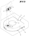
- FIG. 3 shows the household appliance 1 and the user terminal 3 during a bidirectional communication.
- an optical code 4 is displayed on the display 5 of the user terminal 3.
- an optical code 7 is displayed on the display 8 of the household appliance 1.
- the household appliance 1 and the user terminal 3 are positioned relative to one another such that the detection area of the image sensor 6 of the household appliance 1 comprises the display 5 of the user terminal 3, and the detection area of the image sensor 9 of the user terminal 3 contains the display 8 of the household appliance 1.
- the invention now works to connect the household appliance 1 to the home network 2 so that first the user terminal 3 is connected to the home network 2 provided by the access point 13.
- the network access information of the access point 13 is usually transmitted to the user terminal 3 via an operator interface, namely here the display 5 of the user terminal 3, for example.
- the household appliance 1 which does not have a user interface to integrate into the home network 2, the user terminal 3 transmits the network access information to the household appliance 1.
- an application is installed, which is the communication with the household appliance 1 is used.
- the user starts the application and opens an input mask in which he enters an SSID of the household appliance 1, an associated password and a name for the household appliance 1.
- the SSID of the household appliance 1 may be provided by the manufacturer, for example, on a print or sticker on the housing of the household appliance 1.
- a QR code in which additionally the network access information for the home network 2 and an application identification are included.
- the generated QR code is displayed on the display 5 of the user terminal 3.
- the user terminal 3 is held with the display 5 in front of the image sensor 6 of the household appliance 1, so that the display 5 projects into the detection range of the image sensor 6.
- the image sensor 6 detects the presence of an optical code 4 within its detection range, optionally after requesting a corresponding detection function by the user, and reads in the optical code 4.
- the image sensor 6 transmits the optical code 4 to an evaluation device of the household appliance 1, which then evaluates the contents of the optical code 4. In this case, it is first checked whether the SSID and the password match the data stored in the household appliance 1. Furthermore, it is checked whether the application identification contained in the optical code 4 coincides with an application identification stored in the household appliance 1, ie whether it is a valid application identification. If a match is found, the network access information is extracted from the optical code 4. The household appliance 1 can then log on to the access point 13 of the home network 2 by means of the network access information.
- FIG. 3 shows a bidirectional communication between the household appliance 1 and the user terminal 3.
- data is simultaneously transmitted to the household appliance 1 from the user terminal 3 at the same time or in terms of time, as well as data from the household appliance 1 to the user terminal 3.
- this embodiment functions as follows, that the user terminal 3 as already with respect to FIGS. 1 and 2 represented, an optical code 4 on its display 5 indicating which an SSID, a password and a name of the household appliance 1, network access information for logging on to the home network 2, and an application identification of the application installed on the user terminal 3.
- the optical code 4 is also a QR code here.
- a control device of the household appliance 1 also generates an optical code 7, which is then brought to display on the display 8 of the household appliance 1.
- the optical code 7 contains, for example, a basic configuration to be set for an application installed on the user terminal 3.
- the household appliance 1 transmits, for example, information about functions of the application, which are suitable for the particular type of household appliance 1.
- the household appliance 1 can also recognize here, on the basis of the application identification encoded in the optical code 4 of the user terminal 3, whether an application suitable for this particular household appliance 1 is present on the user terminal 3. If necessary, the household appliance 1 can otherwise transmit information to the user, which indicates a non-suitable application. This information can be displayed, for example, on the display 8 of the household appliance 1 or first transmitted to the user terminal 3 and then from there to the user.
Abstract
Die Erfindung betrifft ein Verfahren zum Verbinden eines Haushaltsgerätes (1) mit einem drahtlosen Heimnetzwerk (2), wobei Netzwerkzugangsinformationen mittels eines auf einem Nutzerendgerät (3) dargestellten optischen Codes (4) von dem Nutzerendgerät (3) an das Haushaltsgerät (1) übermittelt werden und wobei sich das Haushaltsgerät (1) unter Nutzung der empfangenen Netzwerkzugangsinformationen an dem drahtlosen Heimnetzwerk (2) anmeldet. Um sicherzustellen, dass der optische Code (4) für das Haushaltsgerät (1) geeignet ist, wird vorgeschlagen, dass in dem optischen Code (4) eine Applikations-Identifikation einer den optischen Code (4) generierenden, auf dem Nutzerendgerät (3) installierten Applikation übertragen wird.

Description
Die Anmeldung betrifft ein Verfahren zum Verbinden eines Haushaltsgerätes mit einem drahtlosen Heimnetzwerk, wobei Netzwerkzugangsinformationen mittels eines auf einem Nutzerendgerät dargestellten optischen Codes von dem Nutzerendgerät an das Haushaltsgerät übermittelt werden und wobei sich das Haushaltsgerät unter Nutzung der empfangenen Netzwerkzugangsinformationen an dem drahtlosen Heimnetzwerk anmeldet.The application relates to a method for connecting a home appliance to a home wireless network, wherein network access information is transmitted from the user terminal to the home appliance by means of an optical code displayed on a user terminal and wherein the home appliance logs on to the home wireless network using the received network access information.
Verfahren der vorgenannten Art sind im Stand der Technik bekannt. Diese dienen insbesondere zum Verbinden eines Gerätes, welches selbst nicht über eine manuelle Eingabeschnittstelle verfügt, mit einem Heimnetzwerk. Um das Gerät verbinden zu können, übermittelt ein anderes Gerät die für die Anmeldung an dem Heimnetzwerk erforderlichen Netzwerkzugangsinformationen an das Gerät.Methods of the aforementioned type are known in the art. These are used in particular for connecting a device, which itself does not have a manual input interface, with a home network. To connect the device, another device transmits the network access information required to log in to the home network to the device.
Die Patentschrift
Nachteilig ist dabei, dass das zu verbindende Gerät nicht unterscheiden kann, ob ein von ihm eingelesener optischer Code für dieses Gerät geeignet ist. Daraus können beispielsweise Fehlfunktionen oder andere Fehlerzustände des Gerätes resultieren, insbesondere solche, die eine ordnungsgemäße Verbindung des Gerätes mit dem Heimnetzwerk verhindern oder zumindest erschweren.The disadvantage here is that the device to be connected can not distinguish whether a read-in optical code for this device is suitable. This may result, for example, malfunction or other fault conditions of the device, in particular those that prevent or at least complicate a proper connection of the device to the home network.
Ausgehend von dem vorgenannten Stand der Technik ist es daher Aufgabe der Erfindung, ein verbessertes Verfahren zum Verbinden eines Haushaltsgerätes mit einem Heimnetzwerk zu schaffen, insbesondere in Bezug auf eine fehlerfreie Funktion des Haushaltsgerätes.Based on the aforementioned prior art, it is therefore an object of the invention to provide an improved method for connecting a household appliance to a home network, in particular with respect to a faultless function of the household appliance.
Zur Lösung der vorgenannten Aufgabe wird vorgeschlagen, dass in dem optischen Code eine Applikations-Identifikation einer den optischen Code generierenden, auf dem Nutzerendgerät installierten Applikation übertragen wird.In order to achieve the above object, it is proposed that an application identification of an application which generates the optical code and is installed on the user terminal be transmitted in the optical code.
Erfindungsgemäß ist in dem übertragenen optischen Code nun eine Identifikation enthalten, welche die verwendete und auf dem Nutzerendgerät installierte Applikation identifiziert. Anhand dieser Applikations-Identifikation kann eine Auswerteeinrichtung des Haushaltsgerätes erkennen, dass der optische Code für das Haushaltsgerät geeignet ist. Falls das Haushaltsgerät optische Codes von mehreren Nutzerendgeräten oder einem Nutzerendgerät mit einer veralteten Version der Applikation erhält, kann zumindest einer der optischen Codes als gültig oder nicht gültig identifiziert werden. Somit ist es nicht möglich, dass beispielsweise eine veraltete Applikation zu einer Fehlfunktion oder Nicht-Funktion des Anmeldevorgangs zur Anmeldung des Haushaltsgerätes an dem Heimnetzwerk führt.According to the invention, an identification is now contained in the transmitted optical code which identifies the application used and installed on the user terminal. On the basis of this application identification, an evaluation device of the household appliance can recognize that the optical code is suitable for the household appliance. If the home appliance receives optical codes from multiple user terminals or a user terminal with an outdated version of the application, at least one of the optical codes may be identified as valid or not valid. Thus, it is not possible that, for example, an outdated application leads to a malfunction or non-function of the logon process for logging the home appliance on the home network.
Es wird vorgeschlagen, dass eine Auswerteeinrichtung des Haushaltsgerätes die in dem optischen Code enthaltene Applikations-Identifikation mit einer in dem Haushaltsgerät gespeicherten validen Applikations-Identifikation vergleicht und bei Übereinstimmung die in dem optischen Code enthaltenen Netzwerkzugangsinformationen für eine Anmeldung an dem Heimnetzwerk freigibt. In dem Haushaltsgerät sind eine oder mehrere valide Applikations-Identifikationen gespeichert, welche dann mit einer in einem empfangenen optischen Code enthaltenen Applikations-Identifikation verglichen werden können. Nur wenn eine Übereinstimmung festgestellt wird, verwendet das Nutzerendgerät die in dem Code enthaltenen Netzwerkzugangsinformationen für eine Verbindung mit dem Heimnetzwerk.It is proposed that an evaluation device of the household appliance contains the application identification contained in the optical code compares a valid application identification stored in the household appliance and, if they match, releases the network access information contained in the optical code for logging on to the home network. One or more valid application identifications are stored in the household appliance, which can then be compared with an application identification contained in a received optical code. Only when a match is found does the user terminal use the network access information contained in the code for connection to the home network.
Es wird vorgeschlagen, dass die in dem optischen Code enthaltenen Informationen bei Nicht-Übereinstimmung der Applikations-Identifikation oder bei fehlender Applikations-Identifikation von dem Haushaltsgerät nicht verwendet werden. Sofern keine Übereinstimmung zwischen der in dem Code enthaltenen Applikations-Identifikation und einer in dem Haushaltsgerät gespeicherten Applikations-Identifikation festgestellt werden kann, oder gar keine Applikations-Identifikation in dem übermittelten Code enthalten ist, wird der optische Code von dem Haushaltsgerät ignoriert und nicht weiter verwendet, d. h., dass eine Auswerteeinrichtung des Haushaltsgerätes die Netzwerkzugangsinformationen nicht aus dem optischen Code extrahiert und/ oder verarbeitet und/oder an einen Router oder Access Point des Heimnetzwerkes übermittelt.It is proposed that the information contained in the optical code is not used by the household appliance if the application identification does not match or if there is no application identification. If no match can be found between the application identification contained in the code and an application identification stored in the household appliance, or if no application identification is contained in the transmitted code, the optical code is ignored by the household appliance and is no longer used , d. h. An evaluation device of the household appliance does not extract the network access information from the optical code and / or processed and / or transmitted to a router or access point of the home network.
Insbesondere wird vorgeschlagen, dass der optische Code ein auf einem Display des Nutzerendgerätes dargestellter zweidimensionaler Code ist. Insbesondere kann es sich bei dem optischen Code um einen QR-Code® (Quick Response Code) handeln. Der auf dem Display des Nutzerendgerätes dargestellte zweidimensionale Code kann besonders vorteilhaft ein Schwarzweiß-Muster sein, welches nach der Art eines Barcodes oder eines QR-Codes ausgestaltet ist. Das Muster enthält Informationen in verschlüsselter Form, welche unter anderem auch den Netzwerkzugang zu dem Heimnetzwerk betreffen. Der optische Code wird vorzugsweise als Standbild auf dem Display angezeigt, wobei es jedoch auch vorgesehen sein kann, dass sich der optische Code über eine bestimmte Zeitdauer ändert, beispielsweise im Sinne einzelner aufeinanderfolgender Bilder, in Form eines Videos oder dergleichen. Darüber hinaus ist es selbstverständlich auch möglich, eine Farbcodierung in dem optischen Code vorzusehen. Das Haushaltsgerät bzw. eine Auswerteeinrichtung des Haushaltsgerätes verfügt korrespondierend zu der Art des optischen Codes über Mittel zur Decodierung des optischen Codes und zur Extrahierung der darin enthaltenen Netzwerkzugangsinformationen.In particular, it is proposed that the optical code is a two-dimensional code displayed on a display of the user terminal. In particular, the optical code may be a QR code® (Quick Response Code). The two-dimensional code displayed on the display of the user terminal can be particularly advantageously a black and white pattern, which is designed in the manner of a barcode or a QR code is. The pattern contains information in encrypted form which, among other things, concerns the network access to the home network. The optical code is preferably displayed as a still image on the display, although it may also be provided that the optical code changes over a certain period of time, for example in the sense of individual successive images, in the form of a video or the like. In addition, of course, it is also possible to provide color coding in the optical code. The household appliance or an evaluation device of the household appliance has corresponding to the type of optical code means for decoding the optical code and for extracting the network access information contained therein.
Es wird vorgeschlagen, dass der optische Code mittels eines Bildsensors des Haushaltsgerätes gelesen wird. Dazu wird der Bildsensor des Haushaltsgerätes so vor das Display des Nutzerendgerätes geführt, dass ein Erfassungsbereich des Bildsensors die Oberfläche des Displays enthält. Üblicherweise führt der Nutzer des Haushaltsgerätes sein Nutzerendgerät, beispielsweise ein mobiles Gerät wie ein Mobiltelefon, ein Laptop, einen Tablet-Computer oder dergleichen, vor den Bildsensor des Haushaltsgerätes, so dass der Bildsensor den auf dem Display des Nutzerendgerätes angezeigten optischen Code wahrnehmen kann. Der Bildsensor des Haushaltsgerätes ist vorzugsweise eine Kamera oder ein Kamerachip, welcher an dem Gehäuse des Haushaltsgerätes befestigt ist. Alternativ ist es auch möglich, dass der Bildsensor ein zu dem Haushaltsgerät externer Bildsensor ist, welcher die aufgenommenen Daten an eine Auswerteeinrichtung des Haushaltsgerätes übermittelt.It is proposed that the optical code is read by means of an image sensor of the household appliance. For this purpose, the image sensor of the household appliance is guided in front of the display of the user terminal that a detection range of the image sensor includes the surface of the display. Usually, the user of the household appliance leads his user terminal, such as a mobile device such as a mobile phone, a laptop, a tablet computer or the like, in front of the image sensor of the household appliance, so that the image sensor can perceive the displayed on the display of the user terminal optical code. The image sensor of the household appliance is preferably a camera or a camera chip, which is attached to the housing of the household appliance. Alternatively, it is also possible that the image sensor is an external image sensor to the household appliance, which transmits the recorded data to an evaluation device of the household appliance.
Des Weiteren wird vorgeschlagen, dass der Nutzer mittels der auf dem Nutzerendgerät installierten Applikation eine SSID des Haushaltsgerätes wählt und/oder ein Passwort für das Haushaltsgerät bestimmt und/oder einen Namen für das Haushaltsgerät bestimmt. Beispielsweise kann der Nutzer eine Taste des Nutzerendgerätes drücken, beispielsweise auch einen als Taste dargestellten Bereich eines Touchscreens, welcher die Funktion "Haushaltsgerät hinzufügen" enthält. Nach Drücken dieser physischen oder virtuellen Taste öffnet sich eine Eingabemaske auf dem Display des Nutzerendgerätes, in welcher der Nutzer eine SSID für das Haushaltsgerät, ein zugehöriges Passwort und/oder einen Namen für das Haushaltsgerät eintragen kann. Die vorgenannte Auswahl bzw. die Eingaben können in einer gemeinsamen Eingabemaske vorgenommen werden, oder alternativ in mehreren Masken. Durch Bestätigung der Eingabe, beispielswese mittels erneutem Tastendruck, wird auf dem Display des Nutzerendgerätes ein optischer Code angezeigt, welcher die vorgenannten Informationen, die Netzwerkzugangsinformationen sowie die Applikations-Identifikation enthält.Furthermore, it is proposed that the user selects an SSID of the household appliance by means of the application installed on the user terminal and / or a password for the household appliance and / or determines a name for the household appliance. For example, the user can press a button of the user terminal, for example, also a region of a touchscreen shown as a button, which contains the function "Add home appliance". After pressing this physical or virtual key, an input mask opens on the display of the user terminal, in which the user can enter a SSID for the household appliance, an associated password and / or a name for the household appliance. The aforementioned selection or inputs can be made in a common input mask, or alternatively in several masks. By confirming the input, beispielswese by pressing the button again, an optical code is displayed on the display of the user terminal, which contains the aforementioned information, the network access information and the application identification.
Des Weiteren ist vorgesehen, dass die SSID, das Passwort und/oder der Name mittels des optischen Codes an das Haushaltsgerät übermittelt werden. Zur Übermittlung des optischen Codes hält der Nutzer das Nutzerendgerät so vor das Haushaltsgerät, dass das den optischen Code anzeigende Display von einer entsprechenden Erfassungseinrichtung des Haushaltsgerätes erfasst werden kann, nämlich hier vorzugsweise einer Kamera des Haushaltsgerätes.Furthermore, it is provided that the SSID, the password and / or the name are transmitted to the household appliance by means of the optical code. To transmit the optical code, the user holds the user terminal in front of the household appliance in such a way that the display indicating the optical code can be detected by a corresponding detection device of the household appliance, namely here preferably a camera of the household appliance.
Gemäß einer Ausführungsform wird des Weiteren vorgeschlagen, dass das Haushaltsgerät einen optischen Code erstellt und anzeigt, wobei der optische Code von dem Nutzerendgerät gelesen wird. Gemäß dieser Ausführungsform weist auch das Haushaltsgerät ein Display zur Anzeige eines optischen Codes auf, welcher ebenfalls ein zweidimensionaler Code, wie insbesondere ein QR-Code, sein kann. Der optische Code dient zur Übermittlung von Informationen des Haushaltsgerätes an einen Nutzer des Haushaltsgerätes bzw. ein Nutzerendgerät des Nutzers. Somit ist unter anderem eine bidirektionale Kommunikation zwischen dem Haushaltsgerät und dem Nutzerendgerät möglich. Insbesondere ist es möglich, dass einer Einbindung des Haushaltsgerätes in das Heimnetzwerk ein Dialog mittels eines gegenseitigen Datenaustausches per optischen Codes vorausgeht. Dieser Datenaustausch kann beispielsweise eine gegenseitige Bestätigung beinhalten, dass seitens des Nutzerendgerätes eine originale Applikation eines Herstellers des Haushaltsgerätes betrieben wird, und dass seitens des Haushaltsgerätes ein originales Haushaltsgerät des betreffenden Herstellers verwendet wird. Über diesen gegenseitigen Sicherheitsscheck tauschen das Haushaltsgerät und das Nutzerendgerät Originalzertifikate aus, um eine Netzwerkeinbindung, eine Kommunikation zwischen den Komponenten und eine Steuerung spezifischer Gerätefunktionen sicherzustellen.According to one embodiment, it is further proposed that the household appliance generates and displays an optical code, wherein the optical code is read by the user terminal. According to this embodiment, the domestic appliance also has a display for displaying an optical code, which may also be a two-dimensional code, in particular a QR code. The optical code is used to transmit information from the household appliance to a user of the household appliance or a User terminal of the user. Thus, among other things, a bidirectional communication between the household appliance and the user terminal is possible. In particular, it is possible that an integration of the household appliance into the home network precedes a dialogue by means of a mutual data exchange by means of optical codes. This data exchange may include, for example, a mutual confirmation that the user terminal an original application of a manufacturer of the household appliance is operated, and that the part of the household appliance, an original home appliance of the manufacturer in question is used. Through this mutual security check, the home appliance and the user terminal exchange original certificates to ensure network connectivity, inter-component communication, and control of specific device functions.
Insbesondere kann vorgesehen sein, dass das Haushaltsgerät in dem optischen Code eine einzustellende Konfiguration für die auf dem Nutzerendgerät installierte Applikation übermittelt. Durch diese Ausgestaltung lassen sich insbesondere spezifische Funktionen des Haushaltsgerätes steuern. Beispielsweise kann eine Grundkonfiguration der Applikation für einen bestimmten Haushaltsgerät-Typus vorgenommen werden, so dass nur für diesen bestimmten Haushaltsgerät-Typus geeignete Funktionen in der Applikation zur Verfügung stehen. Andererseits kann das Haushaltsgerät erkennen, ob eine für das Haushaltsgerät geeignete Applikation auf dem Nutzerendgerät vorhanden ist und den Nutzer gegebenenfalls auf eine ungeeignete Applikation aufmerksam machen bzw. eine Verbindung mit der Applikation ablehnen.In particular, it can be provided that the household appliance transmits in the optical code a configuration to be set for the application installed on the user terminal. By this embodiment, in particular specific functions of the household appliance can be controlled. For example, a basic configuration of the application for a particular household appliance type can be made so that suitable functions are available in the application only for this particular household appliance type. On the other hand, the household appliance can detect whether an application suitable for the household appliance is present on the user terminal and possibly make the user aware of an unsuitable application or reject a connection with the application.
Das zuvor beschriebene Verfahren kann in Verbindung mit unterschiedlichen Haushaltsgeräten verwendet werden. Insbesondere eignet sich das Verfahren bei Haushaltsrobotern, wie beispielsweise Bodenbearbeitungsrobotern, wie Saugrobotern, Wischrobotern, Polierrobotern, Mährobotern und dergleichen. Des Weiteren kann das Haushaltsgerät auch mehrere dieser oder anderer Funktionen aufweisen. Grundsätzlich ist es ebenfalls möglich, dass das Haushaltsgerät ein von einem Nutzer handgeführtes Haushaltsgerät ist, beispielsweise ein von einem Nutzer handgeführter Staubsauger oder dergleichen. Des Weiteren kann das Haushaltsgerät auch ein Vorsatzgerät für ein Haushaltsgerät sein, ein Zubehör oder dergleichen. Insbesondere eignet sich das Verfahren bei solchen Haushaltsgeräten, die selbst nicht über eine Benutzerschnittstelle zur Eingabe der Netzwerkzugangsinformationen verfügen.The method described above can be used in conjunction with various household appliances. In particular, the method is suitable for household robots, such as tillage robots, such as vacuum robots, wiping robots, polishing robots, robotic lawnmowers and the like. Furthermore, the household appliance may also have several of these or other functions. In principle, it is likewise possible for the domestic appliance to be a domestic appliance which is guided by a user, for example a vacuum cleaner or the like hand-operated by a user. Furthermore, the household appliance may also be an attachment for a household appliance, an accessory or the like. In particular, the method is suitable for household appliances which themselves do not have a user interface for entering the network access information.
Im Folgenden wird die Erfindung anhand von Ausführungsbeispielen näher erläutert. Es zeigen:
- Fig. 1
- ein Heimnetzwerk mit einem Haushaltsgerät, einem Nutzerendgerät und einem Access Point,
- Fig. 2
- das Haushaltsgerät und das Nutzerendgerät während einer Übermittlung eines optischen Codes von dem Nutzerendgerät an das Haushaltsgerät,
- Fig. 3
- das Haushaltsgerät und das Nutzerendgerät während einer bidirektionalen Kommunikation.
- Fig. 1
- a home network with a home appliance, a user terminal and an access point,
- Fig. 2
- the household appliance and the user terminal during a transmission of an optical code from the user terminal to the household appliance,
- Fig. 3
- the home appliance and the user terminal during bidirectional communication.
Das Haushaltsgerät 1 weist eine nicht weiter dargestellte Navigations- und Selbstlokalisierungseinrichtung auf, mittels welcher sich das Haushaltsgerät 1 innerhalb einer Umgebung orientieren und fortbewegen kann. Die Navigations- und Selbstlokalisierungseinrichtung wertet Messdaten einer Abstandsmesseinrichtung 11 auf, welche hier beispielsweise ein Rundum-Laserscanner nach der Art eines Lasertriangulationsmesssystems ist. Mittels der Abstandsmesseinrichtung 11 werden Abstände zu Hindernissen und Raumbegrenzungen gemessen. Diese Messdaten werden vorzugsweise mit Messdaten eines Odometriesensors verglichen, welcher eine von dem Haushaltsgerät 1 zurückgelegte Strecke erfasst. Die Informationen über Hindernisse und Raumbegrenzungen der Umgebung werden zu einer Umgebungskarte des Haushaltsgerätes 1 weiterverarbeitet, mit deren Hilfe sich das Haushaltsgerät 1 in der Umgebung orientieren kann. Des Weiteren weist das Haushaltsgerät 1 ein Reinigungselement 10 zur Bearbeitung einer zu reinigenden Fläche auf. Das Reinigungselement 10 ist hier beispielsweise eine elektromotorisch angetriebene Borstenwalze. Das Haushaltsgerät 1 verfügt über mehrere Räder 12, welche motorisch angetrieben sind und der Fortbewegung des Haushaltsgerätes 1 innerhalb der Umgebung dienen. Das Haushaltsgerät 1 verfügt zudem über einen Bildsensor 6, hier eine Kamera. Auf einer Oberseite des Haushaltsgerätes 1 ist des Weiteren ein Display 8 angeordnet, auf welchem verschiedene Informationen angezeigt werden können.The
Das Nutzerendgerät 3 weist ein Display 5 und einen Bildsensor 9, nämlich eine Kamera, auf. Auf dem Display 5 ist ein optischer Code 4 in Form eines QR-Codes dargestellt, auf welchen im Folgenden noch weiter eingegangen wird.The
Die Erfindung funktioniert zur Verbindung des Haushaltsgerätes 1 mit dem Heimnetzwerk 2 nun so, dass zunächst das Nutzerendgerät 3 mit dem von dem Access Point 13 bereitgestellten Heimnetzwerk 2 verbunden wird. Dazu werden üblicherweise über eine Bedienschnittstelle, nämlich hier beispielsweise das Display 5 des Nutzerendgerätes 3, die Netzwerkzugangsinformationen des Access Points 13 an das Nutzerendgerät 3 übermittelt. Um davon ausgehend auch das Haushaltsgerät 1, welches nicht über eine Benutzerschnittstelle verfügt, in das Heimnetzwerk 2 einzubinden, übermittelt das Nutzerendgerät 3 die Netzwerkzugangsinformationen an das Haushaltsgerät 1. Dazu ist es erforderlich, dass auf dem Nutzerendgerät 3 eine Applikation installiert ist, welche der Kommunikation mit dem Haushaltsgerät 1 dient. Der Nutzer startet die Applikation und öffnet eine Eingabemaske, in welcher er eine SSID des Haushaltsgerätes 1, ein zugehöriges Passwort und einen Namen für das Haushaltsgerät 1 eingibt. Die SSID des Haushaltsgerätes 1 kann herstellerseitig beispielsweise auf einem Aufdruck oder Aufkleber auf dem Gehäuse des Haushaltsgerätes 1 bereitgestellt sein. Nach einer Bestätigung der getätigten Eingaben durch den Nutzer wird mittels der Applikation ein QR-Code generiert, in welchen zusätzlich die Netzwerkzugangsinformationen für das Heimnetzwerk 2 und eine Applikations-Identifikation eingebunden werden. Der generierte QR-Code wird auf dem Display 5 des Nutzerendgerätes 3 angezeigt. Um den optischen Code 4 bzw. die darin enthaltenen Netzwerkzugangsinformationen nun an das Haushaltsgerät 1 zu übermitteln, wird das Nutzerendgerät 3 mit dem Display 5 vor den Bildsensor 6 des Haushaltsgerätes 1 gehalten, so dass das Display 5 in den Erfassungsbereich des Bildsensors 6 ragt. Der Bildsensor 6 erkennt die Anwesenheit eines optischen Codes 4 innerhalb seines Erfassungsbereiches, gegebenenfalls nach Anforderung einer entsprechenden Erfassungsfunktion durch den Nutzer, und liest den optischen Code 4 ein. Der Bildsensor 6 übermittelt den optischen Code 4 an eine Auswerteeinrichtung des Haushaltsgerätes 1, welche die Inhalte des optischen Codes 4 daraufhin auswertet. Dabei wird zunächst geprüft, ob die SSID und das Passwort mit in dem Haushaltsgerät 1 hinterlegten Daten übereinstimmen. Des Weiteren wird überprüft, ob die in dem optischen Code 4 enthaltene Applikations-Identifikation mit einer in dem Haushaltsgerät 1 gespeicherten Applikations-Identifikation übereinstimmt, d. h. ob es sich um eine valide Applikations-Identifikation handelt. Sofern eine Übereinstimmung gefunden wird, wird die Netzwerkzugangsinformation aus dem optischen Code 4 extrahiert. Daraufhin kann sich das Haushaltsgerät 1 mittels der Netzwerkzugangsinformationen an dem Access Point 13 des Heimnetzwerkes 2 anmelden.The invention now works to connect the
Des Weiteren können über die bidirektionale Kommunikation mittels der optischen Codes 4, 7 Originalzertifikate des Nutzerendgerätes 3 und des Haushaltsgerätes 1 ausgetauscht werden, so dass eine Netzwerkeinbindung, eine Kommunikation zwischen den Komponenten und eine Steuerung der spezifischen Gerätefunktionen sichergestellt ist. Des Weiteren kann das Haushaltsgerät 1 auch hier anhand der in dem optischen Code 4 des Nutzerendgerätes 3 codierten Applikations-Identifikation erkennen, ob eine für dieses spezielle Haushaltsgerät 1 geeignete Applikation auf dem Nutzerendgerät 3 vorhanden ist. Gegebenenfalls kann das Haushaltsgerät 1 andernfalls eine Information an den Nutzer übermitteln, welche auf eine nicht geeignete Applikation hinweist. Dieser Hinweis kann beispielsweise auf dem Display 8 des Haushaltsgerätes 1 angezeigt werden oder zunächst an das Nutzerendgerät 3 und dann von dort aus an den Nutzer übermittelt werden.Furthermore, via the bidirectional communication by means of the
- 11
- Haushaltsgeräthousehold appliance
- 22
- HeimnetzwerkHome Network
- 33
- Nutzerendgerätuser terminal
- 44
- Optischer CodeOptical code
- 55
- Displaydisplay
- 66
- Bildsensorimage sensor
- 77
- Optischer CodeOptical code
- 88th
- Displaydisplay
- 99
- Bildsensorimage sensor
- 1010
- Reinigungselementcleaning element
- 1111
- AbstandsmesseinrichtungDistance measuring device
- 1212
- Radwheel
- 1313
- Access PointAccess point
Claims (9)
Applications Claiming Priority (1)
| Application Number | Priority Date | Filing Date | Title |
|---|---|---|---|
| DE102017107087.7A DE102017107087A1 (en) | 2017-04-03 | 2017-04-03 | A method of connecting a home appliance to a home wireless network |
Publications (2)
| Publication Number | Publication Date |
|---|---|
| EP3386153A1 true EP3386153A1 (en) | 2018-10-10 |
| EP3386153B1 EP3386153B1 (en) | 2019-11-13 |
Family
ID=61801846
Family Applications (1)
| Application Number | Title | Priority Date | Filing Date |
|---|---|---|---|
| EP18163296.9A Active EP3386153B1 (en) | 2017-04-03 | 2018-03-22 | Method for connecting a domestic appliance with a wireless domestic network |
Country Status (7)
| Country | Link |
|---|---|
| US (1) | US10939482B2 (en) |
| EP (1) | EP3386153B1 (en) |
| JP (1) | JP2018181320A (en) |
| CN (1) | CN108696409B (en) |
| DE (1) | DE102017107087A1 (en) |
| ES (1) | ES2763146T3 (en) |
| TW (1) | TW201842753A (en) |
Cited By (2)
| Publication number | Priority date | Publication date | Assignee | Title |
|---|---|---|---|---|
| EP3569126A4 (en) * | 2017-01-13 | 2020-07-08 | LG Electronics Inc. -1- | Household electrical appliance for registering information and method for registering information relating to household electrical appliance |
| AT522953B1 (en) * | 2020-03-17 | 2021-04-15 | Gharb Samy | Remote control system in seconds with mobile phone and optical reader |
Families Citing this family (3)
| Publication number | Priority date | Publication date | Assignee | Title |
|---|---|---|---|---|
| US11240854B2 (en) | 2017-08-22 | 2022-02-01 | AI Incorporated | Methods and systems for pairing mobile robotic device docking stations with a wireless router and cloud service |
| CN110209070A (en) * | 2019-04-10 | 2019-09-06 | 浙江捷昌线性驱动科技股份有限公司 | The means of communication, device and same table based on two dimensional code |
| CN111383368A (en) * | 2020-03-13 | 2020-07-07 | 巴江物联技术(东莞)有限公司 | Configuration method for intelligent door lock, display terminal, intelligent door lock and server |
Citations (3)
| Publication number | Priority date | Publication date | Assignee | Title |
|---|---|---|---|---|
| US20080250122A1 (en) * | 2006-11-06 | 2008-10-09 | Ikan Technologies, Inc. | Methods and systems for network configuration |
| FR2938393A1 (en) * | 2008-11-10 | 2010-05-14 | Gostai | Method for connecting communicating robot to wireless access point e.g. router, involves utilizing values of predetermined parameters to establish connection between communicating equipment and access point |
| WO2014036272A1 (en) * | 2012-08-29 | 2014-03-06 | Siemens Industry, Inc. | Shared configuration data in a building automation system controller |
Family Cites Families (19)
| Publication number | Priority date | Publication date | Assignee | Title |
|---|---|---|---|---|
| JP3207192B1 (en) * | 2000-05-02 | 2001-09-10 | 株式会社 ジェネス | Authentication method and device |
| DE102005001723B4 (en) * | 2005-01-13 | 2009-06-18 | Infineon Technologies Ag | Data processing device, method for controlling a data processing device using a graphic code, data carrier, on which a machine-readable computer program is stored, and computer program element |
| JP2006261938A (en) * | 2005-03-16 | 2006-09-28 | Sony Corp | Communications system, communications apparatus and method, recording medium, and program |
| US8823494B1 (en) * | 2010-11-19 | 2014-09-02 | Logitech Europe S.A. | Systems and methods for wireless device connection and pairing |
| KR101330807B1 (en) * | 2011-08-31 | 2013-11-18 | 주식회사 팬택 | Apparatus and method for sharing data using augmented reality |
| US9143402B2 (en) * | 2012-02-24 | 2015-09-22 | Qualcomm Incorporated | Sensor based configuration and control of network devices |
| US20140013100A1 (en) * | 2012-07-05 | 2014-01-09 | Martin M. Menzel | Establish bidirectional wireless communication between electronic devices using visual codes |
| US20140087661A1 (en) * | 2012-09-24 | 2014-03-27 | Lg Electronics Inc. | Home appliance using terminal and operating method thereof |
| US10735408B2 (en) * | 2013-03-14 | 2020-08-04 | Samsung Electronics Co., Ltd. | Application connection for devices in a network |
| TW201607357A (en) * | 2014-08-07 | 2016-02-16 | 國立臺北科技大學 | Toning control method of WiFi device setting by smart device |
| US20160121487A1 (en) * | 2014-11-03 | 2016-05-05 | Qualcomm Incorporated | Communicating Configurable Instruction Sets to Robots for Controlling Robot Behavior |
| CN104581997B (en) * | 2014-12-29 | 2018-07-06 | 广东欧珀移动通信有限公司 | A kind of mobile WIFI hot spot connection method and mobile equipment |
| JP6482299B2 (en) * | 2015-01-30 | 2019-03-13 | キヤノン株式会社 | COMMUNICATION DEVICE, COMMUNICATION DEVICE CONTROL METHOD, AND PROGRAM |
| WO2016202827A1 (en) * | 2015-06-18 | 2016-12-22 | Hicof Inc. | Authentication feature in a barcode |
| US9946874B2 (en) * | 2015-08-06 | 2018-04-17 | International Business Machines Corporation | Authenticating application legitimacy |
| CN105306264A (en) * | 2015-10-09 | 2016-02-03 | 四川长虹电器股份有限公司 | Network configuration and remote registration binding method and system for intelligent household appliance |
| CN105553798A (en) * | 2016-01-29 | 2016-05-04 | 青岛海尔智能家电科技有限公司 | Method for verifying device, device and instant messaging APP (Application) binding method and related apparatus |
| CN106385347A (en) * | 2016-09-09 | 2017-02-08 | 珠海格力电器股份有限公司 | Household appliances control method and device |
| US10691788B2 (en) * | 2017-02-03 | 2020-06-23 | Ademco Inc. | Systems and methods for provisioning a camera with a dynamic QR code and a BLE connection |
-
2017
- 2017-04-03 DE DE102017107087.7A patent/DE102017107087A1/en not_active Withdrawn
-
2018
- 2018-03-22 ES ES18163296T patent/ES2763146T3/en active Active
- 2018-03-22 EP EP18163296.9A patent/EP3386153B1/en active Active
- 2018-03-23 JP JP2018055770A patent/JP2018181320A/en active Pending
- 2018-04-02 TW TW107111662A patent/TW201842753A/en unknown
- 2018-04-03 US US15/943,862 patent/US10939482B2/en active Active
- 2018-04-03 CN CN201810288879.2A patent/CN108696409B/en active Active
Patent Citations (3)
| Publication number | Priority date | Publication date | Assignee | Title |
|---|---|---|---|---|
| US20080250122A1 (en) * | 2006-11-06 | 2008-10-09 | Ikan Technologies, Inc. | Methods and systems for network configuration |
| FR2938393A1 (en) * | 2008-11-10 | 2010-05-14 | Gostai | Method for connecting communicating robot to wireless access point e.g. router, involves utilizing values of predetermined parameters to establish connection between communicating equipment and access point |
| WO2014036272A1 (en) * | 2012-08-29 | 2014-03-06 | Siemens Industry, Inc. | Shared configuration data in a building automation system controller |
Cited By (4)
| Publication number | Priority date | Publication date | Assignee | Title |
|---|---|---|---|---|
| EP3569126A4 (en) * | 2017-01-13 | 2020-07-08 | LG Electronics Inc. -1- | Household electrical appliance for registering information and method for registering information relating to household electrical appliance |
| US11071153B2 (en) | 2017-01-13 | 2021-07-20 | Lg Electronics Inc. | Home appliance for information registration and method for registering information of home appliance |
| AT522953B1 (en) * | 2020-03-17 | 2021-04-15 | Gharb Samy | Remote control system in seconds with mobile phone and optical reader |
| AT522953A4 (en) * | 2020-03-17 | 2021-04-15 | Gharb Samy | Remote control system in seconds with mobile phone and optical reader |
Also Published As
| Publication number | Publication date |
|---|---|
| DE102017107087A1 (en) | 2018-10-04 |
| EP3386153B1 (en) | 2019-11-13 |
| CN108696409A (en) | 2018-10-23 |
| ES2763146T3 (en) | 2020-05-27 |
| TW201842753A (en) | 2018-12-01 |
| US20180288817A1 (en) | 2018-10-04 |
| US10939482B2 (en) | 2021-03-02 |
| CN108696409B (en) | 2022-08-16 |
| JP2018181320A (en) | 2018-11-15 |
Similar Documents
| Publication | Publication Date | Title |
|---|---|---|
| EP3386153B1 (en) | Method for connecting a domestic appliance with a wireless domestic network | |
| EP3427906B1 (en) | Method for operating an automatically moving robot | |
| DE102013220865A1 (en) | Method and system for remote operation of a machine tool by means of a mobile communication device | |
| EP3281076B1 (en) | Method for processing a floor | |
| DE10226610A1 (en) | Method and system for transferring data between a digital camera and a host | |
| DE102014007915A1 (en) | Method and device for remote control of a function of a vehicle by means of a mobile unit | |
| WO2016020165A1 (en) | Method for operating a field device | |
| EP2894816A1 (en) | Method of establishing a wireless communication connection between at least two household appliances | |
| EP3386154B1 (en) | Method for connecting a household appliance to a wireless home network | |
| DE102014112033B4 (en) | Electric measuring device with coding unit for generating QR codes | |
| EP3455121B1 (en) | Method for controlling a process for providing motor vehicles in a parking environment, and operating system for a parking environment | |
| EP3590279B1 (en) | Method, system and application program for the assignment of industrial field devices in a cloud environment | |
| DE60117197T2 (en) | Communication system and method for identifying a person by means of biological information | |
| DE102015217385A1 (en) | Method and device for determining whether an object is located in the environment of a motor vehicle located within a parking space | |
| EP3451589B1 (en) | Method for connecting a domestic appliance with a wireless home network | |
| EP2634652B1 (en) | Device for configuration of at least one device involved in building system technology or door communication | |
| EP3298350B1 (en) | System and method for intelligently coupling and connecting mobile terminals to a coordinate-measuring device | |
| EP3489800A1 (en) | Safety system | |
| WO2015007315A1 (en) | Method for wirelessly transmitting information from an auxiliary unit to a floor cleaning unit, and floor cleaning device | |
| EP3812869B1 (en) | Method for creating an environment map for an automatically moving earth working device, and system comprising two automatically moving earth working devices | |
| EP3833565B1 (en) | Method and a display device for visualising an arrangement and method of operation of surroundings sensors of a motor vehicle | |
| DE102008015652A1 (en) | Hand-guided detection device for detecting handwritten or printed symbols or texts, has detecting unit for detecting symbols or texts and transformation unit for transforming detected symbols or texts in digital data | |
| EP2916272A1 (en) | Method and system for quality assurance of services and computer program product for carrying out the method | |
| EP3298464B1 (en) | Remote maintenance system having a mobile remote maintenance unit, and configuration method | |
| DE102008056258A1 (en) | Data-entry system is provided for scanning information displayed on screen, and information is scanned by reading device, where signals representing scanned information are supplied to processor as input signals |
Legal Events
| Date | Code | Title | Description |
|---|---|---|---|
| PUAI | Public reference made under article 153(3) epc to a published international application that has entered the european phase |
Free format text: ORIGINAL CODE: 0009012 |
|
| STAA | Information on the status of an ep patent application or granted ep patent |
Free format text: STATUS: THE APPLICATION HAS BEEN PUBLISHED |
|
| AK | Designated contracting states |
Kind code of ref document: A1 Designated state(s): AL AT BE BG CH CY CZ DE DK EE ES FI FR GB GR HR HU IE IS IT LI LT LU LV MC MK MT NL NO PL PT RO RS SE SI SK SM TR |
|
| AX | Request for extension of the european patent |
Extension state: BA ME |
|
| STAA | Information on the status of an ep patent application or granted ep patent |
Free format text: STATUS: REQUEST FOR EXAMINATION WAS MADE |
|
| 17P | Request for examination filed |
Effective date: 20190307 |
|
| RBV | Designated contracting states (corrected) |
Designated state(s): AL AT BE BG CH CY CZ DE DK EE ES FI FR GB GR HR HU IE IS IT LI LT LU LV MC MK MT NL NO PL PT RO RS SE SI SK SM TR |
|
| GRAP | Despatch of communication of intention to grant a patent |
Free format text: ORIGINAL CODE: EPIDOSNIGR1 |
|
| STAA | Information on the status of an ep patent application or granted ep patent |
Free format text: STATUS: GRANT OF PATENT IS INTENDED |
|
| RIC1 | Information provided on ipc code assigned before grant |
Ipc: G06K 7/10 20060101ALI20190510BHEP Ipc: H04W 4/33 20180101ALI20190510BHEP Ipc: H04W 76/11 20180101ALI20190510BHEP Ipc: H04L 12/24 20060101ALI20190510BHEP Ipc: H04L 12/28 20060101AFI20190510BHEP |
|
| INTG | Intention to grant announced |
Effective date: 20190604 |
|
| GRAS | Grant fee paid |
Free format text: ORIGINAL CODE: EPIDOSNIGR3 |
|
| GRAA | (expected) grant |
Free format text: ORIGINAL CODE: 0009210 |
|
| STAA | Information on the status of an ep patent application or granted ep patent |
Free format text: STATUS: THE PATENT HAS BEEN GRANTED |
|
| AK | Designated contracting states |
Kind code of ref document: B1 Designated state(s): AL AT BE BG CH CY CZ DE DK EE ES FI FR GB GR HR HU IE IS IT LI LT LU LV MC MK MT NL NO PL PT RO RS SE SI SK SM TR |
|
| REG | Reference to a national code |
Ref country code: CH Ref legal event code: EP Ref country code: AT Ref legal event code: REF Ref document number: 1202828 Country of ref document: AT Kind code of ref document: T Effective date: 20191115 |
|
| REG | Reference to a national code |
Ref country code: DE Ref legal event code: R096 Ref document number: 502018000354 Country of ref document: DE |
|
| REG | Reference to a national code |
Ref country code: IE Ref legal event code: FG4D Free format text: LANGUAGE OF EP DOCUMENT: GERMAN |
|
| REG | Reference to a national code |
Ref country code: NL Ref legal event code: MP Effective date: 20191113 |
|
| REG | Reference to a national code |
Ref country code: LT Ref legal event code: MG4D |
|
| PG25 | Lapsed in a contracting state [announced via postgrant information from national office to epo] |
Ref country code: PL Free format text: LAPSE BECAUSE OF FAILURE TO SUBMIT A TRANSLATION OF THE DESCRIPTION OR TO PAY THE FEE WITHIN THE PRESCRIBED TIME-LIMIT Effective date: 20191113 Ref country code: NL Free format text: LAPSE BECAUSE OF FAILURE TO SUBMIT A TRANSLATION OF THE DESCRIPTION OR TO PAY THE FEE WITHIN THE PRESCRIBED TIME-LIMIT Effective date: 20191113 Ref country code: SE Free format text: LAPSE BECAUSE OF FAILURE TO SUBMIT A TRANSLATION OF THE DESCRIPTION OR TO PAY THE FEE WITHIN THE PRESCRIBED TIME-LIMIT Effective date: 20191113 Ref country code: LV Free format text: LAPSE BECAUSE OF FAILURE TO SUBMIT A TRANSLATION OF THE DESCRIPTION OR TO PAY THE FEE WITHIN THE PRESCRIBED TIME-LIMIT Effective date: 20191113 Ref country code: BG Free format text: LAPSE BECAUSE OF FAILURE TO SUBMIT A TRANSLATION OF THE DESCRIPTION OR TO PAY THE FEE WITHIN THE PRESCRIBED TIME-LIMIT Effective date: 20200213 Ref country code: FI Free format text: LAPSE BECAUSE OF FAILURE TO SUBMIT A TRANSLATION OF THE DESCRIPTION OR TO PAY THE FEE WITHIN THE PRESCRIBED TIME-LIMIT Effective date: 20191113 Ref country code: PT Free format text: LAPSE BECAUSE OF FAILURE TO SUBMIT A TRANSLATION OF THE DESCRIPTION OR TO PAY THE FEE WITHIN THE PRESCRIBED TIME-LIMIT Effective date: 20200313 Ref country code: NO Free format text: LAPSE BECAUSE OF FAILURE TO SUBMIT A TRANSLATION OF THE DESCRIPTION OR TO PAY THE FEE WITHIN THE PRESCRIBED TIME-LIMIT Effective date: 20200213 Ref country code: GR Free format text: LAPSE BECAUSE OF FAILURE TO SUBMIT A TRANSLATION OF THE DESCRIPTION OR TO PAY THE FEE WITHIN THE PRESCRIBED TIME-LIMIT Effective date: 20200214 Ref country code: LT Free format text: LAPSE BECAUSE OF FAILURE TO SUBMIT A TRANSLATION OF THE DESCRIPTION OR TO PAY THE FEE WITHIN THE PRESCRIBED TIME-LIMIT Effective date: 20191113 |
|
| REG | Reference to a national code |
Ref country code: ES Ref legal event code: FG2A Ref document number: 2763146 Country of ref document: ES Kind code of ref document: T3 Effective date: 20200527 |
|
| PG25 | Lapsed in a contracting state [announced via postgrant information from national office to epo] |
Ref country code: RS Free format text: LAPSE BECAUSE OF FAILURE TO SUBMIT A TRANSLATION OF THE DESCRIPTION OR TO PAY THE FEE WITHIN THE PRESCRIBED TIME-LIMIT Effective date: 20191113 Ref country code: IS Free format text: LAPSE BECAUSE OF FAILURE TO SUBMIT A TRANSLATION OF THE DESCRIPTION OR TO PAY THE FEE WITHIN THE PRESCRIBED TIME-LIMIT Effective date: 20200313 Ref country code: HR Free format text: LAPSE BECAUSE OF FAILURE TO SUBMIT A TRANSLATION OF THE DESCRIPTION OR TO PAY THE FEE WITHIN THE PRESCRIBED TIME-LIMIT Effective date: 20191113 |
|
| PGFP | Annual fee paid to national office [announced via postgrant information from national office to epo] |
Ref country code: CZ Payment date: 20200312 Year of fee payment: 3 |
|
| PG25 | Lapsed in a contracting state [announced via postgrant information from national office to epo] |
Ref country code: AL Free format text: LAPSE BECAUSE OF FAILURE TO SUBMIT A TRANSLATION OF THE DESCRIPTION OR TO PAY THE FEE WITHIN THE PRESCRIBED TIME-LIMIT Effective date: 20191113 |
|
| PG25 | Lapsed in a contracting state [announced via postgrant information from national office to epo] |
Ref country code: RO Free format text: LAPSE BECAUSE OF FAILURE TO SUBMIT A TRANSLATION OF THE DESCRIPTION OR TO PAY THE FEE WITHIN THE PRESCRIBED TIME-LIMIT Effective date: 20191113 Ref country code: DK Free format text: LAPSE BECAUSE OF FAILURE TO SUBMIT A TRANSLATION OF THE DESCRIPTION OR TO PAY THE FEE WITHIN THE PRESCRIBED TIME-LIMIT Effective date: 20191113 Ref country code: EE Free format text: LAPSE BECAUSE OF FAILURE TO SUBMIT A TRANSLATION OF THE DESCRIPTION OR TO PAY THE FEE WITHIN THE PRESCRIBED TIME-LIMIT Effective date: 20191113 |
|
| REG | Reference to a national code |
Ref country code: DE Ref legal event code: R097 Ref document number: 502018000354 Country of ref document: DE |
|
| PG25 | Lapsed in a contracting state [announced via postgrant information from national office to epo] |
Ref country code: SM Free format text: LAPSE BECAUSE OF FAILURE TO SUBMIT A TRANSLATION OF THE DESCRIPTION OR TO PAY THE FEE WITHIN THE PRESCRIBED TIME-LIMIT Effective date: 20191113 Ref country code: SK Free format text: LAPSE BECAUSE OF FAILURE TO SUBMIT A TRANSLATION OF THE DESCRIPTION OR TO PAY THE FEE WITHIN THE PRESCRIBED TIME-LIMIT Effective date: 20191113 |
|
| PLBE | No opposition filed within time limit |
Free format text: ORIGINAL CODE: 0009261 |
|
| STAA | Information on the status of an ep patent application or granted ep patent |
Free format text: STATUS: NO OPPOSITION FILED WITHIN TIME LIMIT |
|
| 26N | No opposition filed |
Effective date: 20200814 |
|
| PG25 | Lapsed in a contracting state [announced via postgrant information from national office to epo] |
Ref country code: MC Free format text: LAPSE BECAUSE OF FAILURE TO SUBMIT A TRANSLATION OF THE DESCRIPTION OR TO PAY THE FEE WITHIN THE PRESCRIBED TIME-LIMIT Effective date: 20191113 |
|
| PG25 | Lapsed in a contracting state [announced via postgrant information from national office to epo] |
Ref country code: SI Free format text: LAPSE BECAUSE OF FAILURE TO SUBMIT A TRANSLATION OF THE DESCRIPTION OR TO PAY THE FEE WITHIN THE PRESCRIBED TIME-LIMIT Effective date: 20191113 |
|
| REG | Reference to a national code |
Ref country code: BE Ref legal event code: MM Effective date: 20200331 |
|
| PG25 | Lapsed in a contracting state [announced via postgrant information from national office to epo] |
Ref country code: LU Free format text: LAPSE BECAUSE OF NON-PAYMENT OF DUE FEES Effective date: 20200322 |
|
| PG25 | Lapsed in a contracting state [announced via postgrant information from national office to epo] |
Ref country code: IE Free format text: LAPSE BECAUSE OF NON-PAYMENT OF DUE FEES Effective date: 20200322 |
|
| PG25 | Lapsed in a contracting state [announced via postgrant information from national office to epo] |
Ref country code: BE Free format text: LAPSE BECAUSE OF NON-PAYMENT OF DUE FEES Effective date: 20200331 |
|
| PG25 | Lapsed in a contracting state [announced via postgrant information from national office to epo] |
Ref country code: CZ Free format text: LAPSE BECAUSE OF NON-PAYMENT OF DUE FEES Effective date: 20210322 |
|
| REG | Reference to a national code |
Ref country code: CH Ref legal event code: PL |
|
| PG25 | Lapsed in a contracting state [announced via postgrant information from national office to epo] |
Ref country code: CH Free format text: LAPSE BECAUSE OF NON-PAYMENT OF DUE FEES Effective date: 20210331 Ref country code: LI Free format text: LAPSE BECAUSE OF NON-PAYMENT OF DUE FEES Effective date: 20210331 |
|
| PG25 | Lapsed in a contracting state [announced via postgrant information from national office to epo] |
Ref country code: TR Free format text: LAPSE BECAUSE OF FAILURE TO SUBMIT A TRANSLATION OF THE DESCRIPTION OR TO PAY THE FEE WITHIN THE PRESCRIBED TIME-LIMIT Effective date: 20191113 Ref country code: MT Free format text: LAPSE BECAUSE OF FAILURE TO SUBMIT A TRANSLATION OF THE DESCRIPTION OR TO PAY THE FEE WITHIN THE PRESCRIBED TIME-LIMIT Effective date: 20191113 Ref country code: CY Free format text: LAPSE BECAUSE OF FAILURE TO SUBMIT A TRANSLATION OF THE DESCRIPTION OR TO PAY THE FEE WITHIN THE PRESCRIBED TIME-LIMIT Effective date: 20191113 |
|
| PG25 | Lapsed in a contracting state [announced via postgrant information from national office to epo] |
Ref country code: MK Free format text: LAPSE BECAUSE OF FAILURE TO SUBMIT A TRANSLATION OF THE DESCRIPTION OR TO PAY THE FEE WITHIN THE PRESCRIBED TIME-LIMIT Effective date: 20191113 |
|
| GBPC | Gb: european patent ceased through non-payment of renewal fee |
Effective date: 20220322 |
|
| PG25 | Lapsed in a contracting state [announced via postgrant information from national office to epo] |
Ref country code: GB Free format text: LAPSE BECAUSE OF NON-PAYMENT OF DUE FEES Effective date: 20220322 |
|
| PGFP | Annual fee paid to national office [announced via postgrant information from national office to epo] |
Ref country code: FR Payment date: 20230321 Year of fee payment: 6 |
|
| PGFP | Annual fee paid to national office [announced via postgrant information from national office to epo] |
Ref country code: DE Payment date: 20230320 Year of fee payment: 6 |
|
| P01 | Opt-out of the competence of the unified patent court (upc) registered |
Effective date: 20230517 |
|
| PGFP | Annual fee paid to national office [announced via postgrant information from national office to epo] |
Ref country code: IT Payment date: 20230331 Year of fee payment: 6 Ref country code: ES Payment date: 20230414 Year of fee payment: 6 |