EP3386090A1 - Molecular machine - Google Patents
Molecular machine Download PDFInfo
- Publication number
- EP3386090A1 EP3386090A1 EP17165250.6A EP17165250A EP3386090A1 EP 3386090 A1 EP3386090 A1 EP 3386090A1 EP 17165250 A EP17165250 A EP 17165250A EP 3386090 A1 EP3386090 A1 EP 3386090A1
- Authority
- EP
- European Patent Office
- Prior art keywords
- molecular
- molecular element
- movement
- machine
- dna
- Prior art date
- Legal status (The legal status is an assumption and is not a legal conclusion. Google has not performed a legal analysis and makes no representation as to the accuracy of the status listed.)
- Withdrawn
Links
- 230000033001 locomotion Effects 0.000 claims abstract description 66
- 230000005684 electric field Effects 0.000 claims abstract description 30
- 108090000623 proteins and genes Proteins 0.000 claims description 3
- 102000004169 proteins and genes Human genes 0.000 claims description 3
- 238000009792 diffusion process Methods 0.000 claims description 2
- 108020004414 DNA Proteins 0.000 description 26
- 102000053602 DNA Human genes 0.000 description 26
- 239000000975 dye Substances 0.000 description 15
- 238000000034 method Methods 0.000 description 12
- 238000006243 chemical reaction Methods 0.000 description 11
- 230000009456 molecular mechanism Effects 0.000 description 11
- 230000008859 change Effects 0.000 description 5
- 230000007246 mechanism Effects 0.000 description 5
- 238000010586 diagram Methods 0.000 description 4
- 230000000694 effects Effects 0.000 description 4
- 238000002474 experimental method Methods 0.000 description 4
- 238000004519 manufacturing process Methods 0.000 description 4
- 239000002245 particle Substances 0.000 description 4
- 230000004044 response Effects 0.000 description 4
- 239000000126 substance Substances 0.000 description 4
- 238000003786 synthesis reaction Methods 0.000 description 4
- 238000013459 approach Methods 0.000 description 3
- 230000015572 biosynthetic process Effects 0.000 description 3
- 238000002866 fluorescence resonance energy transfer Methods 0.000 description 3
- 125000000524 functional group Chemical group 0.000 description 3
- 230000004001 molecular interaction Effects 0.000 description 3
- 229920002477 rna polymer Polymers 0.000 description 3
- 108090000790 Enzymes Proteins 0.000 description 2
- 102000004190 Enzymes Human genes 0.000 description 2
- 102000029749 Microtubule Human genes 0.000 description 2
- 108091022875 Microtubule Proteins 0.000 description 2
- 239000000853 adhesive Substances 0.000 description 2
- 230000001070 adhesive effect Effects 0.000 description 2
- 230000008878 coupling Effects 0.000 description 2
- 238000010168 coupling process Methods 0.000 description 2
- 238000005859 coupling reaction Methods 0.000 description 2
- 238000011161 development Methods 0.000 description 2
- 239000007850 fluorescent dye Substances 0.000 description 2
- 239000000499 gel Substances 0.000 description 2
- 238000011065 in-situ storage Methods 0.000 description 2
- 230000003993 interaction Effects 0.000 description 2
- 239000012528 membrane Substances 0.000 description 2
- 210000004688 microtubule Anatomy 0.000 description 2
- 230000000737 periodic effect Effects 0.000 description 2
- BASFCYQUMIYNBI-UHFFFAOYSA-N platinum Chemical compound [Pt] BASFCYQUMIYNBI-UHFFFAOYSA-N 0.000 description 2
- 238000011160 research Methods 0.000 description 2
- 238000004498 smFRET spectroscopy Methods 0.000 description 2
- 238000012546 transfer Methods 0.000 description 2
- YIXZUOWWYKISPQ-UHFFFAOYSA-N ATTO 565 para-isomer Chemical compound [O-]Cl(=O)(=O)=O.C=12C=C3CCC[N+](CC)=C3C=C2OC=2C=C3N(CC)CCCC3=CC=2C=1C1=CC(C(O)=O)=CC=C1C(O)=O YIXZUOWWYKISPQ-UHFFFAOYSA-N 0.000 description 1
- 239000012103 Alexa Fluor 488 Substances 0.000 description 1
- 108091027757 Deoxyribozyme Proteins 0.000 description 1
- 102000010638 Kinesin Human genes 0.000 description 1
- 108010063296 Kinesin Proteins 0.000 description 1
- 108091028043 Nucleic acid sequence Proteins 0.000 description 1
- 108020004682 Single-Stranded DNA Proteins 0.000 description 1
- 238000003556 assay Methods 0.000 description 1
- DMLAVOWQYNRWNQ-UHFFFAOYSA-N azobenzene Chemical compound C1=CC=CC=C1N=NC1=CC=CC=C1 DMLAVOWQYNRWNQ-UHFFFAOYSA-N 0.000 description 1
- 230000031018 biological processes and functions Effects 0.000 description 1
- 238000013378 biophysical characterization Methods 0.000 description 1
- 238000001311 chemical methods and process Methods 0.000 description 1
- 238000007385 chemical modification Methods 0.000 description 1
- 238000010276 construction Methods 0.000 description 1
- 230000001276 controlling effect Effects 0.000 description 1
- 238000007796 conventional method Methods 0.000 description 1
- 230000001419 dependent effect Effects 0.000 description 1
- 238000013461 design Methods 0.000 description 1
- 238000009429 electrical wiring Methods 0.000 description 1
- 238000005516 engineering process Methods 0.000 description 1
- 230000005284 excitation Effects 0.000 description 1
- 238000001298 force spectroscopy Methods 0.000 description 1
- 239000000446 fuel Substances 0.000 description 1
- PCHJSUWPFVWCPO-UHFFFAOYSA-N gold Chemical compound [Au] PCHJSUWPFVWCPO-UHFFFAOYSA-N 0.000 description 1
- 239000010931 gold Substances 0.000 description 1
- 229910052737 gold Inorganic materials 0.000 description 1
- 238000010438 heat treatment Methods 0.000 description 1
- 238000009396 hybridization Methods 0.000 description 1
- 238000000338 in vitro Methods 0.000 description 1
- 238000010348 incorporation Methods 0.000 description 1
- 239000010954 inorganic particle Substances 0.000 description 1
- 230000010354 integration Effects 0.000 description 1
- 239000000463 material Substances 0.000 description 1
- 238000005259 measurement Methods 0.000 description 1
- 230000010534 mechanism of action Effects 0.000 description 1
- 230000001404 mediated effect Effects 0.000 description 1
- 229910052751 metal Inorganic materials 0.000 description 1
- 239000002184 metal Substances 0.000 description 1
- 238000001000 micrograph Methods 0.000 description 1
- 230000004899 motility Effects 0.000 description 1
- 239000002105 nanoparticle Substances 0.000 description 1
- 230000003287 optical effect Effects 0.000 description 1
- 230000000144 pharmacologic effect Effects 0.000 description 1
- 229910052697 platinum Inorganic materials 0.000 description 1
- 230000025600 response to UV Effects 0.000 description 1
- 238000012216 screening Methods 0.000 description 1
- 239000004065 semiconductor Substances 0.000 description 1
- 238000004627 transmission electron microscopy Methods 0.000 description 1
- 229910052727 yttrium Inorganic materials 0.000 description 1
Images

Classifications
-
- H—ELECTRICITY
- H02—GENERATION; CONVERSION OR DISTRIBUTION OF ELECTRIC POWER
- H02N—ELECTRIC MACHINES NOT OTHERWISE PROVIDED FOR
- H02N1/00—Electrostatic generators or motors using a solid moving electrostatic charge carrier
- H02N1/002—Electrostatic motors
- H02N1/004—Electrostatic motors in which a body is moved along a path due to interaction with an electric field travelling along the path
-
- B—PERFORMING OPERATIONS; TRANSPORTING
- B82—NANOTECHNOLOGY
- B82B—NANOSTRUCTURES FORMED BY MANIPULATION OF INDIVIDUAL ATOMS, MOLECULES, OR LIMITED COLLECTIONS OF ATOMS OR MOLECULES AS DISCRETE UNITS; MANUFACTURE OR TREATMENT THEREOF
- B82B1/00—Nanostructures formed by manipulation of individual atoms or molecules, or limited collections of atoms or molecules as discrete units
- B82B1/003—Devices comprising elements which are movable in relation to each other, e.g. slidable or rotatable
-
- C—CHEMISTRY; METALLURGY
- C12—BIOCHEMISTRY; BEER; SPIRITS; WINE; VINEGAR; MICROBIOLOGY; ENZYMOLOGY; MUTATION OR GENETIC ENGINEERING
- C12Q—MEASURING OR TESTING PROCESSES INVOLVING ENZYMES, NUCLEIC ACIDS OR MICROORGANISMS; COMPOSITIONS OR TEST PAPERS THEREFOR; PROCESSES OF PREPARING SUCH COMPOSITIONS; CONDITION-RESPONSIVE CONTROL IN MICROBIOLOGICAL OR ENZYMOLOGICAL PROCESSES
- C12Q1/00—Measuring or testing processes involving enzymes, nucleic acids or microorganisms; Compositions therefor; Processes of preparing such compositions
- C12Q1/68—Measuring or testing processes involving enzymes, nucleic acids or microorganisms; Compositions therefor; Processes of preparing such compositions involving nucleic acids
Definitions
- the invention regards the field of nanotechnology and describes the utilization of electric fields for the manipulation of molecular mechanisms. In this way, a molecular machine is provided, which allows movement in response to said electrical fields.
- kinesin motors and microtubules were deployed, e.g., for the transport of nanoparticles (cf. prior art references 1 to 3).
- in vitro motility assays kinesin motors were fixed on lithographically patterned chip surfaces to transport microtubules through lithographically produced channel systems.
- electric manipulation was also used e.g. for the sorting of microtubules (cf. prior art reference 4).
- Prior art reference 22 describes a biosensor including a gold platform. This biosensor allows only binary switching between an adhesive state and a non-adhesive state. No fine adjustment of the movement is possible.
- Prior art reference 23 describes the movement of molecular mechanisms in response to UV light.
- the object is therefore solved by a molecular machine comprising a movement part and a control part.
- the movement part comprises several machine elements which are adapted to be moved with respect to each other. These machine parts are molecular structures, particularly nanomolecular structures.
- the movement part includes a first molecular element, a second molecular element and a linking element.
- the first molecular element and the second molecular element preferably are separate and/or independent elements.
- the linking element is adapted to constrain a relative movement of the first molecular element and the second molecular element while allowing a relative movement between the first molecular element and the second molecular element in at least one degree of freedom.
- the first molecular element and the second molecular element can not be separated from each other and establish a moving mechanism with the linking element acting as bearing and/or joint.
- the control part is configured to generate an electrical field around the movement part.
- the control part includes an electrical device which applies said electrical field.
- the first molecular element is fixed relative to the control part such that the first molecular element is fixed relative to the electrical field generating means. Hence, even a change in the electrical field cannot cause a movement of the first molecular element.
- the first molecular element rather acts as a base for movement of the second molecular element.
- the second molecular element is therefore the only part which can be moved in response to the electrical field.
- the second molecular element is electrically charged.
- the second molecular element can be an electrically charged molecule, particularly a biomolecule, or can be artificially electrically charged.
- an electrically charged functional group can be added to a molecular structure in order to create the electrically charged second molecular element. Due to the electrical charge, the second molecular element aligns to said electrical field. In case the electrical field is changed in orientation, the orientation of the second molecular element is also changed. This means that the control part can control fine adjustment of the second molecular element with respect to the first molecular element.
- the second molecular element can be transferred to and held in any orientation with respect to the first molecular element that is not prevented by the linking element. Additionally, a continuous movement of the second molecular element can be realized.
- the movement part sets up the kinematics of the molecular machine, while the control part powers and controls any movement of said kinematics via electric actuation.
- Electric actuation solves several technical challenges that are currently faced by molecular nanomachines.
- electric actuation allows controlling molecular switches and mechanisms faster, with higher precision, and with less complex instrumentation compared to conventional methods.
- the invention offers the solution to a central challenge of nanomanipulation (the "fat fingers" problem) since the externally controlled nanomanipulators are of the same small length scale as the manipulated nanoscale objects and molecules.
- control part comprises a fluidic channel.
- the movement part is provided in the fluidic channel.
- the control part further comprises an electrical device including electrodes.
- the electrodes are connected to the fluidic channel.
- the electrical device comprises a voltage source and electrical wiring to apply the voltage to the electrodes.
- the electrical device comprises two electrodes for generating the electrical field.
- the voltage source can be a three-phase voltage source such that the electrical device has three electrodes. This allows providing a rotating electrical field such that the second molecular element can be rotated in a simple way.
- control part comprises at least two electrical devices and fluidic channels with different orientations.
- the fluidic channels are arranged to intersect at an intersection area and the movement part is placed at the intersection area. Therefore, a two-dimensional movement of the second molecular element can be controlled.
- the above described three-phase voltage and the three electrodes might be used for two-dimensional movement control.
- the first molecular element is fixed to the fluidic channel. This means that the first molecular element can not move in response to the electrical field.
- the molecular element rather is a fixed base for the movement of the second molecular element. In this way, it is ensured that only the second molecular element can be moved. Further the fixation of the first molecular element allows very fine adjustment of the second molecular element, which aligns to the electrical field while the first molecular element does not move and/or align to the electrical field.
- the electrical device preferably includes an isolating element for isolating the electrodes from the movement part.
- the isolating elements particularly comprise membranes and/or gels and/or salt bridges. This means that only selected molecules can pass through the isolating elements such that the electrodes are separated from the movement part.
- the electrical field generated by the electrical devices is not influenced or at least not significantly influenced by the isolating element. Therefore, the control of movement of the second molecular element is not affected.
- the isolating element preferably also reduces the volume provided for reactions. This particularly allows holding the components of a desired reaction close to the movement part such that the components can manipulated and/or moved by the molecular machine.
- the linking element is favorably part of the first molecular element or the second molecular element.
- the first molecular element and/or the second molecular element might comprise a functional group which is adapted to link the first molecular element and the second molecular element.
- the linking element can be part of at least one of two or more mechanically interlocked molecules. This is particularly preferred in a case in which the movement part comprises rotaxanes.
- the first molecular element comprises a linear part and the linking element and the second molecular element comprises a ring structure. The ring structure can rotate about the linear part and the linking element avoids the ring structure slipping off the linear part.
- the first molecular element and/or the second molecular element and/or the linking element preferably are biomolecules.
- the biomolecules are particularly electrically charged.
- the first molecular element and/or the second molecular element and/or the linking element are made of DNA (deoxyribonucleic acid), preferably DNA-origami, and/or RNA (ribonucleic acid) and/or protein and/or artificial charged supramolecular structures.
- the first molecular element is a platform and the second molecular element is a positioning arm.
- the positioning arm is fixed to the platform via the linking element.
- the linking element constrains all relative movement of the first molecular element and the second molecular element except of a rotation of the second molecular element within a plane parallel to the first molecular element. Therefore, the positioning arm is preferably moved by aligning to two overlaid electrical fields. This allows adjusting the positioning arm in relation to the platform. Particularly, a full rotation of the positioning arm is possible, wherein the positioning arm can be stopped and hold in any position. Further, high forces are generated which allow manipulation of further molecules.
- the first molecular element and/or the second molecular element are addressable. This means, that functional groups can be provided on the first molecular element and the second molecular element. Preferably, both, the first molecular element and the second molecular element can be addressed. Therefore, the movement part can be adapted to specific needs. This allows employing the molecular machine in various environments and/or for various purposes.
- fluctuations of the first molecular element and/or the second molecular element due to diffusion are within a tolerance of at most 10 nm, preferably at most 1 nm, particularly preferable at most 0.5 nm. Hence, a fine adjustment of the second molecular element is facilitated.
- any dimension of the first molecular element and the second molecular element is less than 1000 nm.
- the above described platform is preferably made of square shape with a length of 50 nm.
- the positioning arm is preferably shorter than said length.
- the positioning arm is adequately addressable within the overlap with the platform.
- Such dimensions allow manipulation of molecules with the molecular machine. Therefore, the molecular machine is a molecular nanomechanism.
- Figure 1 is a schematic view of a movement part 2 of a molecular machine 1 according to an embodiment of the invention.
- the movement part 2 comprises a platform 4, which corresponds to the first molecular element.
- a position arm 5 is mounted, which corresponds to the second molecular element.
- a linking element 6 constrains the relative movement between platform 4 and positioning arm 5 such that the only possible relative movement is a rotation of the positioning arm 5 in a plane parallel to the platform 4.
- Platform 4 and positioning arm 5 are constructed with the DNA origami method.
- the DNA origami method is well-known in the art and is for example described in prior art references 17 to 18.
- the square platform 4 consists of two layers of DNA double helices. In all figures, each double helix is represented by a cylinder.
- the positioning arm 5 is a six helix bundle.
- the linking element 7 comprises two DNA strands and connects the positioning arm 5 to the platform 4. Transmission electron microscopy micrographs can show the structure and quality of these objects.
- the platform 4 and the positioning arm 5 can be built from different molecules e.g. RNA, proteins, artificial charged supramolecular structures.
- the positioning arm 5 might be elongated by coupling to further structures. An example for such elongation is described with respect to figure 4 .
- DNA molecules and thus also DNA origami structures are heavily charged biomolecules that can be electrophoretically manipulated. This fact can be exploited to achieve control and movement of molecular mechanisms.
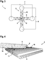
- FIG. 2 is a schematic view of the molecular machine 1 including a control part 3 according to a first alternative
- figure 3 is a schematic view of the molecular machine including a control part 3 according to a second alternative.
- a fluidic channel 9 is provided which is contacted by platinum electrodes 11 of an electrical device 7.
- the movement part 2 is placed in the center of this fluidic channel 7, preferably as far away from the electrodes as possible.
- Isolating elements 13 might be provided in order to isolate the electrodes 13 from the movement part 2.
- the Isolating elements 13 preferably comprise membranes, gels or salt bridges. The isolating elements 13 do not allow transfer of selected molecules such that the electrodes are separated form the movement part 2 such that no unwanted traveling of elements from the movement part 2 to the electrodes 11 can take place. This avoids unwanted electrochemical influences of the electrodes 11.
- Electric control is achieved by applying voltages to the electrodes.
- low control voltages as output channels of a DAQ board (data acquisition board) are amplified to adequate voltages by an operational amplifier.
- the electrical device 7 applies voltages of 200 V.
- the control part 3 comprises a first electrical device 7 and a second electrical device 8, both are identical to the above described electrical device of figure 2 .
- the first electrical device 7 is connected to a first fluidic channel 9 and the second electrical device 9 is connected to a second fluidic channel 10, wherein the first fluidic channel 9 and second fluidic channel 10 are both identical as the above described fluidic channel of figure 2 .
- the first fluidic channel 9 and the second fluidic channel 10 intersect at an intersection area 12 and are orientated perpendicular to each other.
- the movement part 2 is placed in the intersection area 12. Due to such a design, the electrical fields of the first electrical device 7 and the second electrical device 8 are superposed. Superposition of electrical fields in the fluidic channels 9, 10 allows to adjust the positioning arm 5 in arbitrary angles or to rotate it in circles relative to the platform 4.
- the platform 4 is fixed to at least one of the fluidic channels 9, 10 of the control part 3. In this way, the platform is fixed relative to the control part 3 which means that no movement of the platform 4 is possible in response to the electrical field.
- lithographically designed microelectrodes can be used, which require much smaller voltages for manipulation. In principle, this enables the miniaturization of the whole setup and the integration e.g. on a USB-Stick.
- the electrically charged positioning arm 5 aligns to the electrical fields generated via the first electrical device 7 and the second electrical device 8. In this way, an exact positioning of the positioning arm 5 can be reached. Particularly, the positioning arm 5 can be moved with a tolerance of at most 1 nm.
- Evidence for the electro-controlled movement of positioning arms 5 can be provided in several ways.
- Figure 4 is a sketch of the DNA platform 4 with the positioning arm 5 that is modified with a blue donor dye 15.
- the platform 4 was labeled at two positions with a green first acceptor dye 16 and red second acceptor dye 17, respectively.
- the positioning arm 5 movement can be proven via single molecule FRET (fluorescence resonance energy transfer). Further, for better electric coupling (via the DNA-structures charge) and to enable direct optical observation an additional lever/pointer structure 14 is provided to extend the positioning arm 5 to a length of several 100 nm (in this example ⁇ 400nm).
- the movement of the positioning arm can be characterized by means of single molecule fluorescence resonance energy transfer (smFRET), which demonstrates the system's positioning precision on the nanometer scale.
- smFRET single molecule fluorescence resonance energy transfer
- Alexa Fluor 488 is employed
- the green first acceptor dye 16 is employed
- the red second acceptor dye 17, ATTO 647N is employed.
- the blue donor dye 15 can excite the first acceptor dye 16 and second acceptor dye 17 via FRET if donor and acceptor are in closer proximity than the Foerster radius ( ⁇ 6 nm).
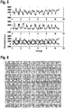
- Figure 5 illustrates a single molecule FRET traces corresponding to the sketch in figure 4 .
- the rotation of the positioning arm 5 is externally driven at 1 Hz while the donor dye 15 on the positioning arm 5 is being excited. This results in an alternating emission of green by the first acceptor dye 16, as shown in the top diagram of figure 5 , and red by the second acceptor dye 17, as shown in the middle diagram of figure 5 .
- An overlay of both traces, which is shown in the bottom diagram of figure 5 clearly shows the periodic alternating excitation.
- the invention can prove a periodic movement of the positioning arm 5 from one position of the platform 4 to the other.
- This experiment also demonstrates the potential of the invention to transport and position molecules on the platform 4, which is of great importance for a wide range of applications.
- Figure 6 shows a montage of single images from a microscope video, which shows the electrically driven rotation of the positioning arm (exposure per frame: 50 ms, Scale bar: 500 nm). Fluorescent dyes are fixed to the tip of positioning arm 5.
- the origami platform 4 is located in the image center and is indicated by a cross. The particle rotates in an external field.
- fluorescent dyes have been placed on the tip of the extension of the positioning arm 5, i.e. on the additional lever/pointer structure 14.
- the positioning arm 5 is rotated in circles with a frequency of 1 Hz.
- the particle at the tip of the positioning arm is performing the desired rotational movement. This also shows the controlled movement of a nanoscale object on a length scale of 1 ⁇ m.
- the movement part 2 of platform 4 and positioning arm 5 make it possible to apply forces to molecules in situ. That is to say, in case of the invention, the force applying lever itself is a molecular structure. Contrary to the other methods mentioned, it is relatively simple to conjugate the molecules and binding partners that are to be characterized to the platform 4 and the positioning arm 5.
- the experimental setup used to create electric forces is much simpler. This enables highly parallelizable execution of force measurements of molecular interaction partners since a vast number of measuring platforms 4 can be actuated at the same time.
- the sensor principle can also be used for screening of molecule libraries by "barcoding" (cf. prior art reference 19) of single platforms 4.
- DNA templated synthesis was established as a novel method to increase the efficiency of chemical reactions and for the sequence based production of molecule libraries. This approach exploits the highly increased local concentration of molecules that were conjugated to a DNA strand and are thereby colocalized by sequence specific base pairing on the template (cf. prior art references 20 and 21).
- This principle can be transferred to reactions with electrically driven molecular mechanisms. Electrically addressable moving molecular mechanisms can bring molecules into close proximity to induce their reaction. In this way for example, the same reaction can be repeated depending on an external clocking signal or sequential reactions can be performed according to a programmable protocol. Contrary to existing "proof of principle" experiments, the possibility of repeated and highly parallelized performance of such reactions enable the production of technologically relevant amounts of substances.
- the invention i.e. the development of the electrical switchable molecular machine 1, is therefore an enabling technology for the realization of genuine molecular robotic systems and molecular assembly lines.
- the molecular actuators according to the invention can readily be modified with inorganic particles like e.g. metal or semiconductor particles.
- inorganic particles like e.g. metal or semiconductor particles.
- a change in position of the molecular mechanisms can vary the particles' orientation with respect to a polarized external field.
- plasmonic effects e.g. field enhancement, energy transfer, heating effects
- nanoscale objects or molecules can be controllably moved and positioned.
- a molecular positioning arm 5 from DNA molecules was explained.
- the nanoscale molecular positioning arm 5 is fixated on a specifically addressable platform 4 with a flexible joint that allows rotation around the pivot point.
- the positioning arm 5 movement can be precisely controlled by external electric fields.
- the positioning arm 5 can transport molecules, control chemical processes and exert forces on other molecules "in situ".
- the method exploits the intrinsic electric charge of biomolecules and can be generally applied to synthetic as well as naturally occurring biomolecular mechanisms.
Landscapes
- Chemical & Material Sciences (AREA)
- Engineering & Computer Science (AREA)
- Organic Chemistry (AREA)
- Life Sciences & Earth Sciences (AREA)
- Nanotechnology (AREA)
- Crystallography & Structural Chemistry (AREA)
- Proteomics, Peptides & Aminoacids (AREA)
- Health & Medical Sciences (AREA)
- Zoology (AREA)
- Wood Science & Technology (AREA)
- Microbiology (AREA)
- Molecular Biology (AREA)
- Physics & Mathematics (AREA)
- Immunology (AREA)
- Biotechnology (AREA)
- Biochemistry (AREA)
- Bioinformatics & Cheminformatics (AREA)
- General Engineering & Computer Science (AREA)
- General Health & Medical Sciences (AREA)
- Genetics & Genomics (AREA)
- Biophysics (AREA)
- Analytical Chemistry (AREA)
- Apparatus Associated With Microorganisms And Enzymes (AREA)
Abstract
The invention regards a molecular machine comprising a movement part (2) including a first molecular element (4), a second molecular element (5), and a linking element (6) for constraining a relative movement of the first molecular element (4) and the second molecular element (5), and a control part configured to generate an electrical field around the movement part (2), wherein the first molecular element (4) is fixed relative to the control part, wherein the second molecular element (5) is movable relative to the first molecular element (4) in at least one degree of freedom, and wherein the second molecular element (5) is electrically charged such that the second molecular element (5) aligns to said electrical field.
Description
- The invention regards the field of nanotechnology and describes the utilization of electric fields for the manipulation of molecular mechanisms. In this way, a molecular machine is provided, which allows movement in response to said electrical fields.
-
- 1. Hess, H.; Bachand, G. D.; Vogel, V., Powering Nanodevices with Biomolecular Motors. .
- 2. van den Heuvel, M. G. L.; Dekker, C., Motor Proteins at Work for Nanotechnology. Science (New York, NY) 2007, 317, 333-336.
- 3. Fischer, T.; Agarwal, A.; Hess, H., A Smart Dust Biosensor Powered by Kinesin Motors. Nature Nanotech. 2009, 4, 162-166.
- 4. van den Heuvel, M. G.; de Graaff, M. P.; Dekker, C., Molecular Sorting by Electrical Steering of Microtubules in Kinesin-Coated Channels. Science (New York, NY) 2006, 312, 910-4.
- 5. Krishnan, Y.; Simmel, F. C., Nucleic Acid Based Molecular Devices. Angew. Chem. Int. Ed. 2011, 50, 3124-3156.
- 6. Kopperger, E.; Pirzer, T.; Simmel, F. C., Diffusive Transport of Molecular Cargo Tethered to a DNA Origami Platform. Nano Lett. 2015, 15, 2693-2699.
- 7. Marras, A. E.; Zhou, L.; Su, H.-J.; Castro, C. E., Programmable Motion of DNA Origami Mechanisms. Proc. Natl. Ac. Sci. 2015, 112, 713-8.
- 8. Ketterer, P.; Willner, E. M.; Dietz, H., Nanoscale Rotary Apparatus Formed from Tight-Fitting 3d DNA Components. Sci .
- 9. List, J.; Falgenhauer, E.; Kopperger, E.; Pardatscher, G.; Simmel, F. C., Long-Range Movement of Large Mechanically Interlocked DNA Nanostructures. Nat Commun 2016, 7, 12414.
- 10. Omabegho, T.; Sha, R.; Seeman, N. C., A Bipedal DNA Brownian Motor with Coordinated Legs. Science 2009, 324, 67-71.
- 11. Green, S.; Bath, J.; Turberfield, A., Coordinated Chemomechanical Cycles: A Mechanism for Autonomous Molecular Motion. Phys. Rev. Lett. 2008, 101, art. no. 238101.
- 12. Liber, M.; Tomov, T. E.; Tsukanov, R.; Berger, Y.; Nir, E., A Bipedal DNA Motor That Travels Back and Forth between Two DNA Origami Tiles. Small 2014, n/a-n/a.
- 13. Wickham, S. F. J.; Endo, M.; Katsuda, Y.; Hidaka, K.; Bath, J.; Sugiyama, H.; Turberfield, A. J., Direct Observation of Stepwise Movement of a Synthetic Molecular Transporter. Nature Nanotech. 2011, 6, 166-169.
- 14. Asanuma, H.; Liang, X.; Yoshida, T.; Komiyama, M., Photocontrol of DNA Duplex Formation by Using Azobenzene-Bearing Oligonucleotides. Chembiochem 2001, 2, 39-44.
- 15. Kang, H.; Liu, H.; Phillips, J. A.; Cao, Z.; Kim, Y.; Chen, Y.; Yang, Z.; Li, J.; Tan, W., Single-DNA Molecule Nanomotor Regulated by Photons. Nano Lett. 2009, 9, 2690-2696.
- 16. Suzuki, Y.; Endo, M.; Yang, Y.; Sugiyama, H., Dynamic Assembly/Disassembly Processes of Photoresponsive DNA Origami Nanostructures Directly Visualized on a Lipid Membrane Surface. J. Am. Chem. Soc. 2014, 136, 1714-1717.
- 17. Rothemund, P. W. K., Folding DNA to Create Nanoscale Shapes and Patterns. Nature 2006, 440, 297-302.
- 18. Douglas, S. M.; Dietz, H.; Liedl, T.; Högberg, B.; Graf, F.; Shih, W. M., Self-Assembly of DNA into Nanoscale Three-Dimensional Shapes. Nature 2009, 459, 414-8.
- 19. Lin, C.; Jungmann, R.; Leifer, A. M.; Li, C.; Levner, D.; Church, G. M.; Shih, W. M.; Yin, P., Submicrometre Geometrically Encoded Fluorescent Barcodes Self-Assembled from DNA. Nature Chem. 2012, 4, 832-839.
- 20. Li, X.; Liu, D. R., DNA-Templated Organic Synthesis: Nature's Strategy for Controlling Chemical Reactivity Applied to Synthetic Molecules. Angew. Chem. Int. Ed. 2004, 43, 4848-4870.
- 21. He, Y.; Liu, D. R., Autonomous Multistep Organic Synthesis in a Single Isothermal Solution Mediated by a DNA Walker. Nature Nanotech. 2010, 5, 778-782.
- 22. Rant, U.; Pringsheim, E.; Kaiser, W.; Arinaga, K.; Knezevic, J.; Tornow, M.; Fujita, S.; Yokoyama, N.; Abstreiter, G., Detection and Size Analysis of Proteins with Switchable DNA Layers. Nano Letters 2009, Vol. 9, No. 4, 1290-1295.
- 23. Yang, Y.; Tashiro, R.; Suzuki, Y.; Emura, T.; Hidaka, K.; Sugijama, H.; Endo, M., A Photoregulated DNA-Based Rotary System and Direct Observation of Its Rotational Movement. Chemistry, 2007, 23, 1-8.
- 24. Campos, R.; Zhang, S.; Majikes, J. M.; Ferraz, L. C. C.; LaBean, T.H.; Dong, M. D.; Ferapotova, E. E., Electronically addressable nanomechanical switching of i-motif DNA origami assembled on basal plane HOPG. ChemComm, 2015, 51, 14111-14114.
- In the past decades, several biomolecular mechanisms and machines have been demonstrated for the application in nanotechnology. However, none of them grew past the "proof of principle" phase.
- Among the naturally occurring molecular machines mainly kinesin motors and microtubules were deployed, e.g., for the transport of nanoparticles (cf.
prior art references 1 to 3). In so-called "in vitro motility assays" kinesin motors were fixed on lithographically patterned chip surfaces to transport microtubules through lithographically produced channel systems. Here electric manipulation was also used e.g. for the sorting of microtubules (cf. prior art reference 4). - In the past years, artificial biomolecular nanomachines were mainly produced on the basis of DNA molecules. The production of DNA machines utilizes the characteristic, sequence specific molecular interactions between DNA strands. Adequate choice of DNA sequences allows to "programmably" construct complex molecular structures from single DNA strands. A combination of relatively flexible single stranded DNA components with more rigid double stranded elements allows the construction of molecular mechanisms in which molecular components can be moved relative to each other. These include "DNA tweezers" as well as various "DNA walker" systems. An overview of such systems is given in
prior art reference 5. With the recent development of the so-called "DNA origami method" it has become much easier to construct larger molecular systems (typically on the length scale of 10 - 100 nm). Recently this method was used to construct basic molecular machine elements, including several rotary joint and linear sliding structures (prior art references 6 to 9). - So far, the described molecular mechanisms have been actuated chemically or in some cases photo-chemically. In the case of chemical actuation, e.g., so-called DNA fuel strands were used to drive the movement of a mechanism through DNA strand hybridization reactions. Due to the slow kinetics of these reactions only very slow motion could be realized (prior art references 10 to 12). The same limitations apply to deoxyribozymes and DNA modifying enzymes (prior art reference 13).
- Alternatively, motion of molecular mechanisms was achieved with a change of buffer conditions, e.g. by a change in pH or a change of the solution's ionic conditions. These methods come with the disadvantage that they unspecifically influence all system components and that buffer conditions are often not compatible with the chemistry of potential applications (e.g. enzymes are not functional in the specific conditions, nanoparticles can aggregate, etc.)
- The aforementioned chemical methods typically require the external addition of solutions. In principle, this can be done with the help of microfluidic systems, which could allow a certain degree of automation. However, such an approach requires rather elaborate instruments and causes high material consumption.
- At first glance, an attractive method for external control of nanomachines is based on photoswitchable molecules, typically derivates of the photoswitchable molecule azobenzene (prior art references 14 to 16). Incorporation of such photoswitches into DNA double strands makes it possible to destabilize them upon light irradiation (in UV range) and stabilize them by irradiation with light of larger wavelength, and this procedure can be used to drive molecular mechanisms. The downside of this method, apart from the necessary chemical modification of the mechanisms, again is the slow and incomplete switching behavior.
- Prior art reference 22 describes a biosensor including a gold platform. This biosensor allows only binary switching between an adhesive state and a non-adhesive state. No fine adjustment of the movement is possible. Prior art reference 23 describes the movement of molecular mechanisms in response to UV light.
- None of the described approaches could ever demonstrate the exertion of a relevant force against an external load.
- It is an object of the present invention to provide a molecular machine which allows quick reaction to control commands, which can generate high forces, and which can provide an exact movement.
- The object is solved by the features of the independent claim. The dependent claims contain advantageous embodiments of the present invention.
- The object is therefore solved by a molecular machine comprising a movement part and a control part. The movement part comprises several machine elements which are adapted to be moved with respect to each other. These machine parts are molecular structures, particularly nanomolecular structures. The movement part includes a first molecular element, a second molecular element and a linking element. The first molecular element and the second molecular element preferably are separate and/or independent elements. The linking element is adapted to constrain a relative movement of the first molecular element and the second molecular element while allowing a relative movement between the first molecular element and the second molecular element in at least one degree of freedom. Preferably, the first molecular element and the second molecular element can not be separated from each other and establish a moving mechanism with the linking element acting as bearing and/or joint.
- In order to control the relative movement of first molecular element and second molecular element, the control part is configured to generate an electrical field around the movement part. Preferably, the control part includes an electrical device which applies said electrical field. The first molecular element is fixed relative to the control part such that the first molecular element is fixed relative to the electrical field generating means. Hence, even a change in the electrical field cannot cause a movement of the first molecular element. The first molecular element rather acts as a base for movement of the second molecular element. The second molecular element is therefore the only part which can be moved in response to the electrical field.
- At least the second molecular element is electrically charged. The second molecular element can be an electrically charged molecule, particularly a biomolecule, or can be artificially electrically charged. In particular, an electrically charged functional group can be added to a molecular structure in order to create the electrically charged second molecular element. Due to the electrical charge, the second molecular element aligns to said electrical field. In case the electrical field is changed in orientation, the orientation of the second molecular element is also changed. This means that the control part can control fine adjustment of the second molecular element with respect to the first molecular element. The second molecular element can be transferred to and held in any orientation with respect to the first molecular element that is not prevented by the linking element. Additionally, a continuous movement of the second molecular element can be realized.
- In summary, the movement part sets up the kinematics of the molecular machine, while the control part powers and controls any movement of said kinematics via electric actuation. Electric actuation solves several technical challenges that are currently faced by molecular nanomachines. In particular, electric actuation allows controlling molecular switches and mechanisms faster, with higher precision, and with less complex instrumentation compared to conventional methods. Moreover, the invention offers the solution to a central challenge of nanomanipulation (the "fat fingers" problem) since the externally controlled nanomanipulators are of the same small length scale as the manipulated nanoscale objects and molecules.
- In a preferred embodiment, the control part comprises a fluidic channel. The movement part is provided in the fluidic channel. The control part further comprises an electrical device including electrodes. The electrodes are connected to the fluidic channel. In this way, the electrical field as described above can be created. The electrical device comprises a voltage source and electrical wiring to apply the voltage to the electrodes. Preferably, the electrical device comprises two electrodes for generating the electrical field. Alternatively, the voltage source can be a three-phase voltage source such that the electrical device has three electrodes. This allows providing a rotating electrical field such that the second molecular element can be rotated in a simple way.
- Preferably, the control part comprises at least two electrical devices and fluidic channels with different orientations. In this way, two independent overlaying electrical fields can be created. The fluidic channels are arranged to intersect at an intersection area and the movement part is placed at the intersection area. Therefore, a two-dimensional movement of the second molecular element can be controlled. Alternatively, the above described three-phase voltage and the three electrodes might be used for two-dimensional movement control.
- Favorably, the first molecular element is fixed to the fluidic channel. This means that the first molecular element can not move in response to the electrical field. The molecular element rather is a fixed base for the movement of the second molecular element. In this way, it is ensured that only the second molecular element can be moved. Further the fixation of the first molecular element allows very fine adjustment of the second molecular element, which aligns to the electrical field while the first molecular element does not move and/or align to the electrical field.
- Providing the electrical device including electrodes might cause unwanted electrochemical effects. Particularly in case the movement part is employed for synthesis purposes, electrochemical effects to the synthesized products should be avoided. Therefore, the electrical device preferably includes an isolating element for isolating the electrodes from the movement part. The isolating elements particularly comprise membranes and/or gels and/or salt bridges. This means that only selected molecules can pass through the isolating elements such that the electrodes are separated from the movement part. However, the electrical field generated by the electrical devices is not influenced or at least not significantly influenced by the isolating element. Therefore, the control of movement of the second molecular element is not affected. The isolating element preferably also reduces the volume provided for reactions. This particularly allows holding the components of a desired reaction close to the movement part such that the components can manipulated and/or moved by the molecular machine.
- The linking element is favorably part of the first molecular element or the second molecular element. Particularly, the first molecular element and/or the second molecular element might comprise a functional group which is adapted to link the first molecular element and the second molecular element. In this way, the manufacturing process of the molecular machine is simplified. Additionally, the linking element can be part of at least one of two or more mechanically interlocked molecules. This is particularly preferred in a case in which the movement part comprises rotaxanes. In such structures, the first molecular element comprises a linear part and the linking element and the second molecular element comprises a ring structure. The ring structure can rotate about the linear part and the linking element avoids the ring structure slipping off the linear part.
- The first molecular element and/or the second molecular element and/or the linking element preferably are biomolecules. The biomolecules are particularly electrically charged. In a further preferred embodiment, the first molecular element and/or the second molecular element and/or the linking element are made of DNA (deoxyribonucleic acid), preferably DNA-origami, and/or RNA (ribonucleic acid) and/or protein and/or artificial charged supramolecular structures.
- In a preferred embodiment, the first molecular element is a platform and the second molecular element is a positioning arm. The positioning arm is fixed to the platform via the linking element. The linking element constrains all relative movement of the first molecular element and the second molecular element except of a rotation of the second molecular element within a plane parallel to the first molecular element. Therefore, the positioning arm is preferably moved by aligning to two overlaid electrical fields. This allows adjusting the positioning arm in relation to the platform. Particularly, a full rotation of the positioning arm is possible, wherein the positioning arm can be stopped and hold in any position. Further, high forces are generated which allow manipulation of further molecules.
- The first molecular element and/or the second molecular element are addressable. This means, that functional groups can be provided on the first molecular element and the second molecular element. Preferably, both, the first molecular element and the second molecular element can be addressed. Therefore, the movement part can be adapted to specific needs. This allows employing the molecular machine in various environments and/or for various purposes.
- Preferably, fluctuations of the first molecular element and/or the second molecular element due to diffusion are within a tolerance of at most 10 nm, preferably at most 1 nm, particularly preferable at most 0.5 nm. Hence, a fine adjustment of the second molecular element is facilitated.
- Preferably, any dimension of the first molecular element and the second molecular element is less than 1000 nm. Particularly, the above described platform is preferably made of square shape with a length of 50 nm. The positioning arm is preferably shorter than said length. Particularly, the positioning arm is adequately addressable within the overlap with the platform. Such dimensions allow manipulation of molecules with the molecular machine. Therefore, the molecular machine is a molecular nanomechanism.
- A specific embodiment will be described together with the attached drawings. In the drawings,
- Fig. 1
- is a schematic view of a moving part of a molecular machine according to an embodiment of the invention,
- Fig. 2
- is a schematic view of a first alternative of a control part of the molecular machine according to the embodiment of the invention,
- Fig. 3
- is a schematic view of a second alternative of a control part of the molecular machine according to the embodiment of the invention,
- Fig. 4
- is a schematic view of the moving part of the molecular machine according to the embodiment of the invention, which is modified for proof of functionality,
- Fig. 5
- is a schematic view of montage of single images from a microscope video showing the movement of the molecular machine according to the embodiment of the invention, and
- Fig. 6
- is a schematic view of a diagram showing movement of the molecular machine according to the embodiment of the invention.
-
Figure 1 is a schematic view of amovement part 2 of amolecular machine 1 according to an embodiment of the invention. In the embodiment, themovement part 2 comprises aplatform 4, which corresponds to the first molecular element. On theplatform 4, aposition arm 5 is mounted, which corresponds to the second molecular element. A linkingelement 6 constrains the relative movement betweenplatform 4 andpositioning arm 5 such that the only possible relative movement is a rotation of thepositioning arm 5 in a plane parallel to theplatform 4. -
Platform 4 andpositioning arm 5 are constructed with the DNA origami method. The DNA origami method is well-known in the art and is for example described in prior art references 17 to 18. Thesquare platform 4 consists of two layers of DNA double helices. In all figures, each double helix is represented by a cylinder. Thepositioning arm 5 is a six helix bundle. The linkingelement 7 comprises two DNA strands and connects thepositioning arm 5 to theplatform 4. Transmission electron microscopy micrographs can show the structure and quality of these objects. - The
platform 4 and thepositioning arm 5 can be built from different molecules e.g. RNA, proteins, artificial charged supramolecular structures. Thepositioning arm 5 might be elongated by coupling to further structures. An example for such elongation is described with respect tofigure 4 . - DNA molecules and thus also DNA origami structures are heavily charged biomolecules that can be electrophoretically manipulated. This fact can be exploited to achieve control and movement of molecular mechanisms.
- Electric fields can be created in a simple electrophoretic or micro-electrophoretic setup. In the embodiment, a
control part 3 is employed, which is shown infigures 2 and3 .Figure 2 is a schematic view of themolecular machine 1 including acontrol part 3 according to a first alternative, whilefigure 3 is a schematic view of the molecular machine including acontrol part 3 according to a second alternative. - As shown in
figure 2 , afluidic channel 9 is provided which is contacted byplatinum electrodes 11 of anelectrical device 7. Themovement part 2 is placed in the center of thisfluidic channel 7, preferably as far away from the electrodes as possible. Isolatingelements 13 might be provided in order to isolate theelectrodes 13 from themovement part 2. The Isolatingelements 13 preferably comprise membranes, gels or salt bridges. The isolatingelements 13 do not allow transfer of selected molecules such that the electrodes are separated form themovement part 2 such that no unwanted traveling of elements from themovement part 2 to theelectrodes 11 can take place. This avoids unwanted electrochemical influences of theelectrodes 11. - Electric control is achieved by applying voltages to the electrodes. For that purpose, low control voltages as output channels of a DAQ board (data acquisition board) are amplified to adequate voltages by an operational amplifier. In the embodiments, the
electrical device 7 applies voltages of 200 V. - Two-dimensional movement of the
positioning arm 5 can be realized with a crossed channel geometry. This is shown infigure 3 . Thecontrol part 3 comprises a firstelectrical device 7 and a secondelectrical device 8, both are identical to the above described electrical device offigure 2 . The firstelectrical device 7 is connected to a firstfluidic channel 9 and the secondelectrical device 9 is connected to a secondfluidic channel 10, wherein the firstfluidic channel 9 and secondfluidic channel 10 are both identical as the above described fluidic channel offigure 2 . The firstfluidic channel 9 and the secondfluidic channel 10 intersect at anintersection area 12 and are orientated perpendicular to each other. Themovement part 2 is placed in theintersection area 12. Due to such a design, the electrical fields of the firstelectrical device 7 and the secondelectrical device 8 are superposed. Superposition of electrical fields in thefluidic channels positioning arm 5 in arbitrary angles or to rotate it in circles relative to theplatform 4. - In order to ensure that only the
positioning arm 5 rotates while theplatform 4 remains still, theplatform 4 is fixed to at least one of thefluidic channels control part 3. In this way, the platform is fixed relative to thecontrol part 3 which means that no movement of theplatform 4 is possible in response to the electrical field. - In an alternative setup, lithographically designed microelectrodes can be used, which require much smaller voltages for manipulation. In principle, this enables the miniaturization of the whole setup and the integration e.g. on a USB-Stick.
- The electrically charged
positioning arm 5 aligns to the electrical fields generated via the firstelectrical device 7 and the secondelectrical device 8. In this way, an exact positioning of thepositioning arm 5 can be reached. Particularly, thepositioning arm 5 can be moved with a tolerance of at most 1 nm. - Evidence for the electro-controlled movement of positioning
arms 5 can be provided in several ways. -
Figure 4 is a sketch of theDNA platform 4 with thepositioning arm 5 that is modified with ablue donor dye 15. Theplatform 4 was labeled at two positions with a greenfirst acceptor dye 16 and redsecond acceptor dye 17, respectively. Thepositioning arm 5 movement can be proven via single molecule FRET (fluorescence resonance energy transfer). Further, for better electric coupling (via the DNA-structures charge) and to enable direct optical observation an additional lever/pointer structure 14 is provided to extend thepositioning arm 5 to a length of several 100 nm (in this example ∼400nm). - The movement of the positioning arm can be characterized by means of single molecule fluorescence resonance energy transfer (smFRET), which demonstrates the system's positioning precision on the nanometer scale. As the
blue donor dye 15, Alexa Fluor 488 is employed, as the greenfirst acceptor dye 16, ATTO 565 is employed, and as the redsecond acceptor dye 17, ATTO 647N is employed. Theblue donor dye 15 can excite thefirst acceptor dye 16 andsecond acceptor dye 17 via FRET if donor and acceptor are in closer proximity than the Foerster radius (∼ 6 nm). -
Figure 5 illustrates a single molecule FRET traces corresponding to the sketch infigure 4 . The rotation of thepositioning arm 5 is externally driven at 1 Hz while thedonor dye 15 on thepositioning arm 5 is being excited. This results in an alternating emission of green by thefirst acceptor dye 16, as shown in the top diagram offigure 5 , and red by thesecond acceptor dye 17, as shown in the middle diagram offigure 5 . An overlay of both traces, which is shown in the bottom diagram offigure 5 , clearly shows the periodic alternating excitation. - As shown in
figure 6 , the invention can prove a periodic movement of thepositioning arm 5 from one position of theplatform 4 to the other. This experiment also demonstrates the potential of the invention to transport and position molecules on theplatform 4, which is of great importance for a wide range of applications. - An alternative way of proof of movement of the
positioning arm 5 is shown inFigure 6. Figure 6 shows a montage of single images from a microscope video, which shows the electrically driven rotation of the positioning arm (exposure per frame: 50 ms, Scale bar: 500 nm). Fluorescent dyes are fixed to the tip ofpositioning arm 5. Theorigami platform 4 is located in the image center and is indicated by a cross. The particle rotates in an external field. Forfigure 6 , fluorescent dyes have been placed on the tip of the extension of thepositioning arm 5, i.e. on the additional lever/pointer structure 14. Thepositioning arm 5 is rotated in circles with a frequency of 1 Hz. As shown on the image series, the particle at the tip of the positioning arm is performing the desired rotational movement. This also shows the controlled movement of a nanoscale object on a length scale of 1 µm. - The key capability to position molecules precisely, fast and electrically controlled as well as the possibility to locally exert directed forces trough molecular mechanisms on the nanoscale enables a wide variety of application opportunities in nanotechnology. Below, three possible areas of application will be briefly discussed.
- Highly specific molecular interactions are responsible for a wide range of biological processes and are also the mechanism of action of pharmacological substances. For this reason, biological research has been focused on the precise biochemical and biophysical characterization of these interactions for quite some time. In biophysical research, the strength of interactions is often analyzed in single molecule experiments. Here special instruments are used to exert forces on the binding partners. This includes experiments with atomic force microscopes, optic tweezers and magnetic tweezers.
- The
movement part 2 ofplatform 4 andpositioning arm 5 according to the described embodiment of the invention make it possible to apply forces to molecules in situ. That is to say, in case of the invention, the force applying lever itself is a molecular structure. Contrary to the other methods mentioned, it is relatively simple to conjugate the molecules and binding partners that are to be characterized to theplatform 4 and thepositioning arm 5. The experimental setup used to create electric forces is much simpler. This enables highly parallelizable execution of force measurements of molecular interaction partners since a vast number ofmeasuring platforms 4 can be actuated at the same time. The sensor principle can also be used for screening of molecule libraries by "barcoding" (cf. prior art reference 19) ofsingle platforms 4. - In the past 15 years, DNA templated synthesis was established as a novel method to increase the efficiency of chemical reactions and for the sequence based production of molecule libraries. This approach exploits the highly increased local concentration of molecules that were conjugated to a DNA strand and are thereby colocalized by sequence specific base pairing on the template (cf. prior art references 20 and 21).
- This principle can be transferred to reactions with electrically driven molecular mechanisms. Electrically addressable moving molecular mechanisms can bring molecules into close proximity to induce their reaction. In this way for example, the same reaction can be repeated depending on an external clocking signal or sequential reactions can be performed according to a programmable protocol. Contrary to existing "proof of principle" experiments, the possibility of repeated and highly parallelized performance of such reactions enable the production of technologically relevant amounts of substances. The invention, i.e. the development of the electrical switchable
molecular machine 1, is therefore an enabling technology for the realization of genuine molecular robotic systems and molecular assembly lines. - The molecular actuators according to the invention can readily be modified with inorganic particles like e.g. metal or semiconductor particles. For instance, a change in position of the molecular mechanisms can vary the particles' orientation with respect to a polarized external field. Accordingly, the occurrence of plasmonic effects (e.g. field enhancement, energy transfer, heating effects) can be switched via electric control.
- With the described invention, nanoscale objects or molecules can be controllably moved and positioned. As an embodiment and for the demonstration of the general working principle a
molecular positioning arm 5 from DNA molecules was explained. The nanoscalemolecular positioning arm 5 is fixated on a specificallyaddressable platform 4 with a flexible joint that allows rotation around the pivot point. Thepositioning arm 5 movement can be precisely controlled by external electric fields. Thepositioning arm 5 can transport molecules, control chemical processes and exert forces on other molecules "in situ". The method exploits the intrinsic electric charge of biomolecules and can be generally applied to synthetic as well as naturally occurring biomolecular mechanisms. -
- 1
- molecular machine
- 2
- movement part
- 3
- control part
- 4
- platform (first molecular element)
- 5
- positioning arm(second molecular element)
- 6
- linking element
- 7
- first electrical device
- 8
- second electrical device
- 9
- first fluidic channel
- 10
- second fluidic channel
- 11
- electrode
- 12
- intersection area
- 13
- isolating element
- 14
- additional lever/pointer structure
- 15
- donor dye
- 16
- first acceptor dye
- 17
- second acceptor dye
Claims (10)
- Molecular machine (1) comprising• a movement part (2) including∘ a first molecular element (4),∘ a second molecular element (5), and∘ a linking element (6) for constraining a relative movement of the first molecular element (4) and the second molecular element (5), and• a control part (3) configured to generate an electrical field around the movement part (2),• wherein the first molecular element (4) is fixed relative to the control part (3),• wherein the second molecular element (5) is movable relative to the first molecular element (4) in at least one degree of freedom, and• wherein the second molecular element (5) is electrically charged such that the second molecular element (5) aligns to said electrical field.
- Molecular machine (1) according to claim 1, characterized in that the control part (3) comprises a fluidic channel (9, 10), in which the movement part (2) is provided, wherein the control part (3) has an electrical device (7, 8) including electrodes (11), which are connected to the fluidic channel (9, 10), for creating the electrical field.
- Molecular machine (1) according to claim 2, characterized in that the control part (3) comprises at least two electrical devices (7, 8) and fluidic channels (9, 10) with different orientations in order to create at least two independent overlaying electrical fields, wherein the fluidic channels (9, 10) are arranged to intersect at an intersection area (12) and the movement part (2) is placed at the intersection area (12).
- Molecular machine (1) according to claim 2 or 3, characterized in that the first molecular element (4) is fixed to the fluidic channel (9, 10).
- Molecular machine (1) according to any one of the claims 2 to 4, characterized in that the electrical device (7, 8) includes an isolating element (13) for isolating the electrodes (11) from the movement part (2).
- Molecular machine (1) according to any one of the previous claims, characterized in that the linking element (6) is part of the first molecular element (4) or the second molecular element (5).
- Molecular machine (1) according to any one of the previous claims, characterized in that the first molecular element (4) and/or the second molecular element (5) and/or the linking element (6) are biomolecules, preferably made of DNA, preferably DNA-origami, and/or RNA and/or protein and/or artificial charged supramolecular structures.
- Molecular machine (1) according to any one of the previous claims, characterized in that the first molecular element (4) is a platform and the second molecular element (5) is a positioning arm, wherein the linking element (6) constrains all relative movement of the first molecular element (4) and the second molecular element (5) except of a rotation of the second molecular element (5) within a plane parallel to the first molecular element (4).
- Molecular machine (1) according to any one of the previous claims, characterized in that fluctuations of the first molecular element (4) and/or the second molecular element (5) due to diffusion are within a tolerance of at most 10 nm, preferably at most 1 nm, particularly preferred at most 0.5 nm.
- Molecular machine (1) according to any one of the previous claims, characterized in that any dimension of the first molecular element (4) and the second molecular element (5) is less than 1000 nm.
Priority Applications (5)
| Application Number | Priority Date | Filing Date | Title |
|---|---|---|---|
| EP17165250.6A EP3386090A1 (en) | 2017-04-06 | 2017-04-06 | Molecular machine |
| DK18714543.8T DK3607646T3 (en) | 2017-04-06 | 2018-04-06 | MOLECULAR MACHINE |
| EP18714543.8A EP3607646B1 (en) | 2017-04-06 | 2018-04-06 | Molecular machine |
| US16/500,602 US11352254B2 (en) | 2017-04-06 | 2018-04-06 | Molecular machine |
| PCT/EP2018/058876 WO2018185295A1 (en) | 2017-04-06 | 2018-04-06 | Molecular machine |
Applications Claiming Priority (1)
| Application Number | Priority Date | Filing Date | Title |
|---|---|---|---|
| EP17165250.6A EP3386090A1 (en) | 2017-04-06 | 2017-04-06 | Molecular machine |
Publications (1)
| Publication Number | Publication Date |
|---|---|
| EP3386090A1 true EP3386090A1 (en) | 2018-10-10 |
Family
ID=58714883
Family Applications (1)
| Application Number | Title | Priority Date | Filing Date |
|---|---|---|---|
| EP17165250.6A Withdrawn EP3386090A1 (en) | 2017-04-06 | 2017-04-06 | Molecular machine |
Country Status (1)
| Country | Link |
|---|---|
| EP (1) | EP3386090A1 (en) |
Cited By (3)
| Publication number | Priority date | Publication date | Assignee | Title |
|---|---|---|---|---|
| CN111146969A (en) * | 2019-12-30 | 2020-05-12 | 浙江大学 | Electrostatic energy capture device based on origami springback mechanism |
| US20240060478A1 (en) * | 2020-12-18 | 2024-02-22 | Vladik AVETISOV | Harvesting of thermal energy by nanomachines |
| US20240247645A1 (en) * | 2021-07-20 | 2024-07-25 | Molecular Machines Corporation Ltd. | Harvesting of thermal energy by nanomachines |
-
2017
- 2017-04-06 EP EP17165250.6A patent/EP3386090A1/en not_active Withdrawn
Non-Patent Citations (21)
| Title |
|---|
| CAMPOS, R.; ZHANG, S.; MAJIKES, J. M.; FERRAZ, L. C. C.; LABEAN, T.H.; DONG, M. D.; FERAPOTOVA, E. E.: "Electronically addressable nanomechanical switching of i-motif DNA origami assembled on basal plane HOPG", CHEMCOMM, vol. 51, 2015, pages 14111 - 14114 |
| DOUGLAS, S. M.; DIETZ, H.; LIEDL, T.; HOGBERG, B.; GRAF, F.; SHIH, W. M.: "Self-Assembly of DNA into Nanoscale Three-Dimensional Shapes", NATURE, vol. 459, 2009, pages 414 - 8, XP002690757, DOI: doi:10.1038/nature08016 |
| ENZO KOPPERGER ET AL: "Diffusive Transport of Molecular Cargo Tethered to a DNA Origami Platform", NANO LETTERS, vol. 15, no. 4, 8 April 2015 (2015-04-08), US, pages 2693 - 2699, XP055410594, ISSN: 1530-6984, DOI: 10.1021/acs.nanolett.5b00351 * |
| FISCHER, T.; AGARWAL, A.; HESS, H.: "A Smart Dust Biosensor Powered by Kinesin Motors", NATURE NANOTECH., vol. 4, 2009, pages 162 - 166, XP055071888, DOI: doi:10.1038/nnano.2008.393 |
| GREEN, S.; BATH, J.; TURBERFIELD, A.: "Coordinated Chemomechanical Cycles: A Mechanism for Autonomous Molecular Motion", PHYS. REV. LETT., vol. 101, 2008 |
| HE, Y.; LIU, D. R.: "Autonomous Multistep Organic Synthesis in a Single Isothermal Solution Mediated by a DNA Walker", NATURE NANOTECH, vol. 5, 2010, pages 778 - 782 |
| HESS, H.; BACHAND, G. D.; VOGEL, V.: "Powering Nanodevices with Biomolecular Motors", CHEMISTRY, vol. 10, 2004, pages 2110 - 6, XP001203432, DOI: doi:10.1002/chem.200305712 |
| KETTERER, P.; WILLNER, E. M.; DIETZ, H.: "Nanoscale Rotary Apparatus Formed from Tight-Fitting 3d DNA Components", SCI ADV, vol. 2, 2016, pages E1501209 |
| KOPPERGER, E.; PIRZER, T.; SIMMEL, F. C.: "Diffusive Transport of Molecular Cargo Tethered to a DNA Origami Platform", NANO LETT, vol. 15, 2015, pages 2693 - 2699, XP055410594, DOI: doi:10.1021/acs.nanolett.5b00351 |
| KRISHNAN, Y.; SIMMEL, F. C.: "Nucleic Acid Based Molecular Devices", ANGEW. CHEM. INT. ED., vol. 50, 2011, pages 3124 - 3156, XP055174893, DOI: doi:10.1002/anie.200907223 |
| LI, X.; LIU, D. R.: "DNA-Templated Organic Synthesis: Nature's Strategy for Controlling Chemical Reactivity Applied to Synthetic Molecules", ANGEW. CHEM. INT. ED., vol. 43, 2004, pages 4848 - 4870, XP002392408 |
| LIN, C.; JUNGMANN, R.; LEIFER, A. M.; LI, C.; LEVNER, D.; CHURCH, G. M.; SHIH, W. M.; YIN, P.: "Submicrometre Geometrically Encoded Fluorescent Barcodes Self-Assembled from DNA", NATURE CHEM., vol. 4, 2012, pages 832 - 839, XP055129063, DOI: doi:10.1038/nchem.1451 |
| LIST, J.; FALGENHAUER, E.; KOPPERGER, E.; PARDATSCHER, G.; SIMMEL, F. C.: "Long-Range Movement of Large Mechanically Interlocked DNA Nanostructures", NAT COMMUN, vol. 7, 2016, pages 12414 |
| MARRAS, A. E.; ZHOU, L.; SU, H.-J.; CASTRO, C. E.: "Programmable Motion of DNA Origami Mechanisms", PROC. NATL. AC. SCI., vol. 112, 2015, pages 713 - 8 |
| OMABEGHO, T.; SHA, R.; SEEMAN, N. C.: "A Bipedal DNA Brownian Motor with Coordinated Legs", SCIENCE, vol. 324, 2009, pages 67 - 71 |
| RANT, U.; PRINGSHEIM, E.; KAISER, W.; ARINAGA, K.; KNEZEVIC, J.; TORNOW, M.; FUJITA, S.; YOKOYAMA, N.; ABSTREITER, G.: "Detection and Size Analysis of Proteins with Switchable DNA Layers", NANO LETTERS, vol. 9, no. 4, 2009, pages 1290 - 1295, XP055082708, DOI: doi:10.1021/nl8026789 |
| ROTHEMUND, P. W. K.: "Folding DNA to Create Nanoscale Shapes and Patterns", NATURE, vol. 440, 2006, pages 297 - 302 |
| SUZUKI, Y.; ENDO, M.; YANG, Y.; SUGIYAMA, H.: "Dynamic Assembly/Disassembly Processes of Photoresponsive DNA Origami Nanostructures Directly Visualized on a Lipid Membrane Surface", J. AM. CHEM. SOC., vol. 136, 2014, pages 1714 - 1717 |
| VAN DEN HEUVEL, M. G. L.; DEKKER, C., MOTOR PROTEINS AT WORK FOR NANOTECHNOLOGY. SCIENCE, vol. 317, 2007, pages 333 - 336 |
| VAN DEN HEUVEL, M. G.; DE GRAAFF, M. P.; DEKKER, C.: "Molecular Sorting by Electrical Steering of Microtubules in Kinesin-Coated Channels", SCIENCE, vol. 312, 2006, pages 910 - 4 |
| YANG, Y.; TASHIRO, R.; SUZUKI, Y.; EMURA, T.; HIDAKA, K.; SUGIJAMA, H.; ENDO, M.: "A Photoregulated DNA-Based Rotary System and Direct Observation of Its Rotational Movement", CHEMISTRY, vol. 23, 2007, pages 1 - 8 |
Cited By (5)
| Publication number | Priority date | Publication date | Assignee | Title |
|---|---|---|---|---|
| CN111146969A (en) * | 2019-12-30 | 2020-05-12 | 浙江大学 | Electrostatic energy capture device based on origami springback mechanism |
| US20240060478A1 (en) * | 2020-12-18 | 2024-02-22 | Vladik AVETISOV | Harvesting of thermal energy by nanomachines |
| US12173697B2 (en) * | 2020-12-18 | 2024-12-24 | Molecular Machines Corporation Ltd. | Harvesting of thermal energy by nanomachines |
| US20240247645A1 (en) * | 2021-07-20 | 2024-07-25 | Molecular Machines Corporation Ltd. | Harvesting of thermal energy by nanomachines |
| US12372070B2 (en) * | 2021-07-20 | 2025-07-29 | Molecular Machines Corporation Ltd. | Harvesting of thermal energy by nanomachines |
Similar Documents
| Publication | Publication Date | Title |
|---|---|---|
| Hess et al. | Powering nanodevices with biomolecular motors | |
| Guo et al. | Electric-field-guided precision manipulation of catalytic nanomotors for cargo delivery and powering nanoelectromechanical devices | |
| Kim et al. | Recent progress on man‐made inorganic nanomachines | |
| Whitesides | The'right'size in nanobiotechnology | |
| Kinbara et al. | Toward intelligent molecular machines: directed motions of biological and artificial molecules and assemblies | |
| Klefenz | Nanobiotechnology: from molecules to systems | |
| Hess et al. | Biomolecular motors | |
| Ma et al. | Microfluidic approaches for microactuators: from fabrication, actuation, to functionalization | |
| EP3607646B1 (en) | Molecular machine | |
| DelRosso et al. | Exploiting molecular motors as nanomachines: the mechanisms of de novo and re-engineered cytoskeletal motors | |
| Noy et al. | Bionanoelectronics with 1D materials | |
| Ariga et al. | Interfacial nanoarchitectonics for molecular manipulation and molecular machine operation | |
| Keya et al. | Synchronous operation of biomolecular engines | |
| Li et al. | Principles of molecular machines at the single-molecule scale | |
| Huang et al. | Biological and biomimetic molecular machines | |
| Vogt et al. | Electrokinetic Torque Generation by DNA Nanorobotic Arms Studied via Single-Molecule Fluctuation Analysis | |
| Nguyen et al. | Multifunctional droplet microfluidic platform for rapid immobilization of oligonucleotides on semiconductor quantum dots | |
| Kim et al. | A DNA Origami Pivot Hinge Driven by DNA Intercalators | |
| List et al. | Electrical Actuation of DNA-Based Nanomechanical Systems | |
| Ehsan et al. | Bio-Molecular Analysis at the Nanoscale | |
| Karaca et al. | Modular Peptide-Based Hybrid Nanoprobes for Bio-Imaging and Bio-Sensing | |
| Wang | Microfabrication Technique Applications: From Passive Particle Manipulation to Active Microswimmers, Micromachines, and Fluidic Control | |
| Shoseyov et al. | Nanobiotechnology overview | |
| Patton et al. | Utilizing DNA Origami Nanostructures with Designed Entropic Springs for High Throughput, Single-Molecule Force Spectroscopy | |
| Marras | Fabricating and Actuating DNA Origami Mechanisms |
Legal Events
| Date | Code | Title | Description |
|---|---|---|---|
| PUAI | Public reference made under article 153(3) epc to a published international application that has entered the european phase |
Free format text: ORIGINAL CODE: 0009012 |
|
| AK | Designated contracting states |
Kind code of ref document: A1 Designated state(s): AL AT BE BG CH CY CZ DE DK EE ES FI FR GB GR HR HU IE IS IT LI LT LU LV MC MK MT NL NO PL PT RO RS SE SI SK SM TR |
|
| AX | Request for extension of the european patent |
Extension state: BA ME |
|
| STAA | Information on the status of an ep patent application or granted ep patent |
Free format text: STATUS: THE APPLICATION IS DEEMED TO BE WITHDRAWN |
|
| 18D | Application deemed to be withdrawn |
Effective date: 20190411 |