EP3386037A1 - Seal member and electrical connector - Google Patents
Seal member and electrical connector Download PDFInfo
- Publication number
- EP3386037A1 EP3386037A1 EP18165108.4A EP18165108A EP3386037A1 EP 3386037 A1 EP3386037 A1 EP 3386037A1 EP 18165108 A EP18165108 A EP 18165108A EP 3386037 A1 EP3386037 A1 EP 3386037A1
- Authority
- EP
- European Patent Office
- Prior art keywords
- shell
- seal
- housing
- electric
- wire
- Prior art date
- Legal status (The legal status is an assumption and is not a legal conclusion. Google has not performed a legal analysis and makes no representation as to the accuracy of the status listed.)
- Granted
Links
Images



Classifications
-
- H—ELECTRICITY
- H01—ELECTRIC ELEMENTS
- H01R—ELECTRICALLY-CONDUCTIVE CONNECTIONS; STRUCTURAL ASSOCIATIONS OF A PLURALITY OF MUTUALLY-INSULATED ELECTRICAL CONNECTING ELEMENTS; COUPLING DEVICES; CURRENT COLLECTORS
- H01R13/00—Details of coupling devices of the kinds covered by groups H01R12/70 or H01R24/00 - H01R33/00
- H01R13/46—Bases; Cases
- H01R13/52—Dustproof, splashproof, drip-proof, waterproof, or flameproof cases
- H01R13/5205—Sealing means between cable and housing, e.g. grommet
- H01R13/5208—Sealing means between cable and housing, e.g. grommet having at least two cable receiving openings
-
- H—ELECTRICITY
- H01—ELECTRIC ELEMENTS
- H01R—ELECTRICALLY-CONDUCTIVE CONNECTIONS; STRUCTURAL ASSOCIATIONS OF A PLURALITY OF MUTUALLY-INSULATED ELECTRICAL CONNECTING ELEMENTS; COUPLING DEVICES; CURRENT COLLECTORS
- H01R13/00—Details of coupling devices of the kinds covered by groups H01R12/70 or H01R24/00 - H01R33/00
- H01R13/46—Bases; Cases
- H01R13/52—Dustproof, splashproof, drip-proof, waterproof, or flameproof cases
- H01R13/5202—Sealing means between parts of housing or between housing part and a wall, e.g. sealing rings
-
- H—ELECTRICITY
- H01—ELECTRIC ELEMENTS
- H01B—CABLES; CONDUCTORS; INSULATORS; SELECTION OF MATERIALS FOR THEIR CONDUCTIVE, INSULATING OR DIELECTRIC PROPERTIES
- H01B5/00—Non-insulated conductors or conductive bodies characterised by their form
- H01B5/12—Braided wires or the like
-
- H—ELECTRICITY
- H01—ELECTRIC ELEMENTS
- H01R—ELECTRICALLY-CONDUCTIVE CONNECTIONS; STRUCTURAL ASSOCIATIONS OF A PLURALITY OF MUTUALLY-INSULATED ELECTRICAL CONNECTING ELEMENTS; COUPLING DEVICES; CURRENT COLLECTORS
- H01R13/00—Details of coupling devices of the kinds covered by groups H01R12/70 or H01R24/00 - H01R33/00
- H01R13/46—Bases; Cases
- H01R13/514—Bases; Cases composed as a modular blocks or assembly, i.e. composed of co-operating parts provided with contact members or holding contact members between them
-
- H—ELECTRICITY
- H01—ELECTRIC ELEMENTS
- H01R—ELECTRICALLY-CONDUCTIVE CONNECTIONS; STRUCTURAL ASSOCIATIONS OF A PLURALITY OF MUTUALLY-INSULATED ELECTRICAL CONNECTING ELEMENTS; COUPLING DEVICES; CURRENT COLLECTORS
- H01R13/00—Details of coupling devices of the kinds covered by groups H01R12/70 or H01R24/00 - H01R33/00
- H01R13/46—Bases; Cases
- H01R13/516—Means for holding or embracing insulating body, e.g. casing, hoods
- H01R13/518—Means for holding or embracing insulating body, e.g. casing, hoods for holding or embracing several coupling parts, e.g. frames
-
- H—ELECTRICITY
- H01—ELECTRIC ELEMENTS
- H01R—ELECTRICALLY-CONDUCTIVE CONNECTIONS; STRUCTURAL ASSOCIATIONS OF A PLURALITY OF MUTUALLY-INSULATED ELECTRICAL CONNECTING ELEMENTS; COUPLING DEVICES; CURRENT COLLECTORS
- H01R13/00—Details of coupling devices of the kinds covered by groups H01R12/70 or H01R24/00 - H01R33/00
- H01R13/62—Means for facilitating engagement or disengagement of coupling parts or for holding them in engagement
- H01R13/621—Bolt, set screw or screw clamp
-
- H—ELECTRICITY
- H01—ELECTRIC ELEMENTS
- H01R—ELECTRICALLY-CONDUCTIVE CONNECTIONS; STRUCTURAL ASSOCIATIONS OF A PLURALITY OF MUTUALLY-INSULATED ELECTRICAL CONNECTING ELEMENTS; COUPLING DEVICES; CURRENT COLLECTORS
- H01R13/00—Details of coupling devices of the kinds covered by groups H01R12/70 or H01R24/00 - H01R33/00
- H01R13/648—Protective earth or shield arrangements on coupling devices, e.g. anti-static shielding
- H01R13/658—High frequency shielding arrangements, e.g. against EMI [Electro-Magnetic Interference] or EMP [Electro-Magnetic Pulse]
- H01R13/6591—Specific features or arrangements of connection of shield to conductive members
- H01R13/6592—Specific features or arrangements of connection of shield to conductive members the conductive member being a shielded cable
- H01R13/6593—Specific features or arrangements of connection of shield to conductive members the conductive member being a shielded cable the shield being composed of different pieces
-
- H—ELECTRICITY
- H01—ELECTRIC ELEMENTS
- H01R—ELECTRICALLY-CONDUCTIVE CONNECTIONS; STRUCTURAL ASSOCIATIONS OF A PLURALITY OF MUTUALLY-INSULATED ELECTRICAL CONNECTING ELEMENTS; COUPLING DEVICES; CURRENT COLLECTORS
- H01R13/00—Details of coupling devices of the kinds covered by groups H01R12/70 or H01R24/00 - H01R33/00
- H01R13/648—Protective earth or shield arrangements on coupling devices, e.g. anti-static shielding
- H01R13/658—High frequency shielding arrangements, e.g. against EMI [Electro-Magnetic Interference] or EMP [Electro-Magnetic Pulse]
- H01R13/6591—Specific features or arrangements of connection of shield to conductive members
- H01R13/6596—Specific features or arrangements of connection of shield to conductive members the conductive member being a metal grounding panel
-
- H—ELECTRICITY
- H01—ELECTRIC ELEMENTS
- H01R—ELECTRICALLY-CONDUCTIVE CONNECTIONS; STRUCTURAL ASSOCIATIONS OF A PLURALITY OF MUTUALLY-INSULATED ELECTRICAL CONNECTING ELEMENTS; COUPLING DEVICES; CURRENT COLLECTORS
- H01R2201/00—Connectors or connections adapted for particular applications
- H01R2201/26—Connectors or connections adapted for particular applications for vehicles
Definitions
- the present invention relates to a seal member achieving the protection from water of an electrical connector provided with a shell made of metal.
- a waterproof connector provided with an electric-wire seal (collective rubber plug) positioned in a rear end portion of a housing of a plug type connector and coming into close contact with the peripheries of a plurality of electric-wires is known from patent JP2010-153072A .
- the electric-wire seal of this patent is integrally formed with a housing seal portion brought into close contact with a housing of a cap type connector from the inside.
- the electric-wire seal positioned in the rear end portion of the plug housing is pressed down with a seal cover.
- another seal member in addition to the electric-wire seal, is positioned between the shell and the plug housing or the cap housing.
- the seal cover with which the shield connector is provided is formed with a lock portion caught or retained in the cylindrical shell.
- the shell encloses the seal cover and the plug type housing. If it is intended that the electric-wire seal should have the function of preventing entry of water between the shell and the housing, it is necessary to position a seal member extending from the positions of the electric-wires to the position of the shell and press down the whole of the seal member against the housing with the seal cover which is retained in the shell. Since an entire region of the seal member through which the electric-wires extend is pressed down with a portion of the seal cover where the lock portion is not formed, the lock portion is formed around a portion of the seal cover through which the electric-wires extend.
- the presence of the lock portion results in a distance from the electric-wires to the shell to be undesirably large, and accordingly the area of the seal member extending from the electric-wires to the shell is correspondingly large, and the area of the seal cover to be pressed down is also large.
- the seal cover has a size suitable for sufficiently pressing down and/or sufficiently locking the seal member.
- the presence of the lock portion causes the seal cover to be thick in a front-rear direction.
- an object of the present invention is to achieve size reduction while maintaining the performance of preventing entry of water which is required for an electrical connector providing an electromagnetic shielding effect.
- the present invention provides a seal member used for an electrical connector, the seal member being configured to be penetrated by an electric-wire extending out rearwardly from a housing enclosed with a shell made of metal, and to be pressed between the housing and a bottom portion of the shell.
- the seal member of the present invention is characterized by being integrally provided with an electric-wire seal portion configured to come into contact with an outer peripheral portion of the electric-wire, a housing seal portion located on an outer end portion of a radial outside of a base portion formed with the electric-wire seal portion, and configured to be pressed against the housing, and a shell seal portion configured to be pressed against at least the bottom portion of the shell.
- the seal member of the present invention is further provided with a peripheral wall protruding frontwardly or rearwardly from the base portion, a predetermined region of the bottom portion of the shell being inserted into the peripheral wall, and wherein the shell seal portion is equivalent to an inner peripheral portion or an outer peripheral portion of the peripheral wall.
- the peripheral wall protrudes rearwardly from the base portion in the vicinity of and radially outside the outer end portion of the base portion.
- An electrical connector of the present invention is provided with a housing configured to be mated with a mating object, a shell made of metal and enclosing the housing, and a seal member configured to be penetrated by an electric-wire extending out rearwardly from the housing.
- the shell has a bottom portion pressing the seal member between the housing and the bottom portion.
- the seal member is integrally provided with an electric-wire seal portion configured to come into contact with an outer peripheral portion of the electric-wire, a housing seal portion located on an outer end portion of a radial outside of a base portion formed with the electric-wire seal portion and configured to be pressed against the housing, and a shell seal portion configured to be pressed against at least the bottom portion of the shell.
- the present invention since the functions of preventing entry of water required for a shielded connector are integrated into one seal member, the number of components is reduced as compared with the case that a plurality of seal members are used.
- the locations for preventing entry of water are, around the electric-wire, between the housing and the electric-wire, and between the shell and the housing. Therefore, the manufacturing cost of the electrical connector, including the component cost and assembly cost, can be reduced.
- Usage of a plurality of seal members requires structures supporting them individually, whereas in the present invention it is only necessary to support one seal member between the housing and the bottom portion of the shell, and therefore the present invention also contributes to size reduction of the electrical connector.
- the seal member can be pressed down with the bottom portion with which the shell is provided, a seal cover is not required. This point also contributes to reduction in the number of components and thus reduction in cost. Furthermore, since the position of the seal portion coming into contact with the shell is not limited by a lock portion of the seal cover, the shell seal portion coming into contact with the shell can be positioned in the vicinity of the electric-wire. This allows the seal member to be positioned in a minimal region minimally required for preventing entry of water, so that the size of the seal member can be reduced.
- An electrical connector 1 (plug type connector) shown in Figure 1 and Figure 2 is provided with a housing 10 from which two electric-wires are led out, a shell 20 for electromagnetic shielding, a seal member 3 ( Figure 3 and Figures 4(a) and 4(b) ) positioned in the housing 10, and a mating-portion seal 12 ( Figure 3 ).
- An end side from which the electric-wires 11 are led out from the electrical connector 1 is defined as a "rear end", and the opposite end mated in a mating direction D1 to a mating connector (cap type connector) is defined as a "front end”.
- the mating connector is typically assembled with a part of a case of a device (metal member 9 in Figure 3 ).
- the electrical connector 1 and the mating connector are suitable for electrical connection of high voltage equipment, such as a PCU (Power Control Unit), installed on a vehicle.
- high voltage equipment such as a PCU (Power Control Unit)
- the electrical connector 1 and the mating connector have an electromagnetic shielding function.
- the electric-wire 11 is a covered electric-wire having a core wire covered with an insulation layer. As shown in Figure 3 , the electric-wire 11 is covered with a braided wire 14 for electromagnetic shielding.
- the braided wire 14 includes interlaced metal wires and, if necessary, a reinforcing material.
- Two electric-wires 11 are positioned inside the braided wire 14. An end portion of the braided wire 14 is connected to an outer peripheral portion of the shell 20.
- Two electric-wires 11 and the braided wire 14 are bundled together containing a waterproof layer and/or member (not shown), thereby constituting a bundle cable 2.
- the bundle cable 2 is typically accommodated in a corrugated tube 15 made of resin.
- a distal end 15A of the corrugated tube 15 is connected with a grommet 16 formed from an elastic material, such as rubber and/or elastomer.
- a distal end 16A of the grommet 16 is retained on the outer peripheral portion of the shell 20 with a bundling member 17.
- the grommet 16 covers the electric-wire 11 and the braided wire 14 extending from the distal end 15A of the corrugated tube 15.
- the shell 20 ( Figure 1 to Figure 3 ) made of metal encloses the housing 10 and portions of a housing (hereinafter, referred to as mating housing 8 ( Figure 3 )) of the mating connector which protrude out of the metal member 9 ( Figure 3 ) .
- An end portion of the braided wire 14 is electrically connected to an outer peripheral wall of the shell 20.
- the housing 10 retains a female terminal 18 made of a metal material.
- the housing 10 is formed from an insulating resin material.
- a two-position electrical connector 1 provided with two female terminals 18 is illustrated.
- the electrical connector 1 may be provided with a single position or three or more positions.
- the female terminals 18 are connected with the respective electric-wires 11.
- a front end portion 10A of the housing 10 is positioned inside the metal member 9 ( Figure 3 ).
- the electric-wire 11 extends rearwardly from a rear end portion of the housing 10.
- the electric-wire 11 extending out from the housing 10 penetrates or extends through the seal member 3 ( Figure 3 ).
- the housing 10 is formed with an accommodating portion 10B ( Figure 3 ) for accommodating a base portion 30 of the seal member 3. In a bottom of the housing portion 10B, an opening is formed (not shown) through which the electrical wires 11 extend.
- a mating-portion seal 12 ( Figure 3 ) formed in an annular shape is fitted on an outer peripheral portion 10C of the housing 10.
- the mating-portion seal 12 is positioned in or around a stepped portion of the outer peripheral portion 10C, and a seal presser 19 prevents the mating-portion seal 12 from becoming detached frontwardly.
- the mating-portion seal 12 elastically deforms radially between the outer peripheral portion 10C and an inner peripheral portion of the mating housing 8.
- the outer peripheral portion 10C is formed with a lock beam 10D ( Figure 3 ) caught in or engaged with the shell 20. A part of the lock beam 10D is inserted into an engagement hole 21A of the shell 20.
- the shell 20 ( Figure 1 to Figure 3 ) entirely encloses the housing 10 except for the front end portion 10A of the housing 10.
- the shell 20 is formed typically by die casting from a metal material, such as an aluminum alloy, a zinc alloy, or the like.
- the material of the shell 20 may be any material as long as it is conductive, and any suitable metal material, whether magnetic or nonmagnetic, may be used for the shell 20.
- a conductive metal material can be used for the material of the braided wire 14 ( Figure 3 ).
- the shell 20 is integrally provided with a side wall 21 enclosing the outer peripheral portion 10C of the housing 10, an attachment portion 22 extending from a front end of the side wall 21, and a shell bottom or rear end portion 23 ( Figure 2 , Figure 3 ) at a rear end of the side wall 21.
- the mating housing 8 is inserted between the side wall 21 and the outer peripheral portion 10C of the housing 10.
- the front end of the side wall 21 is open ( Figure 1 , Figure 3 ), and the front end portion 10A of the housing 10 protrudes from an opening 210 of the side wall 21.
- the shell bottom portion 23 is located at the opposite side or end to the opening 210.
- the rear end of the side wall 21 is closed with the shell bottom portion 23.
- the side wall 21 is formed in a cylindrical shape.
- the attachment portion 22 is fastened to the metal member 9 with a bolt 24 which extends through the attachment portion 22. Contact with a predetermined contact pressure between a back surface of the attachment portion 22 and a surface of the metal member 9 fastened together ensures the required electrical connection between the shell 20 and the metal member 9 for electromagnetic shielding.
- the shell bottom or rear portion 23 presses down or against the seal member 3 positioned in the rear end portion of the housing 10 from behind. Since the shell bottom portion 23 is present, the electrical connector 1 is not provided with a seal cover for pressing against the seal member 3.
- the shell bottom portion 23 is formed with a peripheral groove 231 for accommodating a part of the seal member 3.
- the peripheral groove 231 extends along the entire periphery in the vicinity of a radial outer end or surface of the shell bottom portion 23.
- a plug portion 232 enclosed with or encircled by the peripheral groove 231 is inserted into or positioned within a recessed portion 35 ( Figure 4(b) ) of the seal member 3.
- the electric-wire 11 penetrates or extends through the plug portion 232.
- the electrical connector 1 of the present embodiment is provided with two seal members: the mating-portion seal 12 and the seal member 3. These are formed from an elastic material, such as rubber and/or elastomer.
- the mating-portion seal 12 and the seal member 3 block entry of water into the housings (the inside of the housing 10 and the mating housing 8) in which the terminals are housed.
- the seal member 3 and the grommet 16 block water from reaching the connection location 14A of the braided wire 14.
- the seal member 3 provided with a shell seal portion 33 pressed with or against the shell 20 prevents entry of water between the shell 20 and the housing 10 covered with the shell 20.
- the seal member 3 is a multiple seal member having the function of preventing entry of water at a plurality of locations.
- the main characteristics of the present embodiment are that the shell 20 is provided with a shell bottom portion 23 and that the seal member 3 has portions situated at a plurality of locations required where water entry prevention is required.
- seal member 3 With reference to Figure 3 , Figures 4(a) and 4(b) , the seal member 3 will be described.
- the seal member 3 is sandwiched between the rear end portion of the housing 10 and the shell bottom portion 23.
- the electric-wires 11 extend rearwardly from the housing 10 and extend through the seal member 3.
- the seal member 3 is integrally provided with a base portion 30 interposed between the housing 10 and the shell bottom portion 23, the same number of electric-wire seal portions 31 as the electric-wires 11, a housing seal portion 32, the shell seal portion 33, and a peripheral wall 34.
- the plurality of electric-wire seal portions 31, the housing seal portion 32, the shell seal portion 33, and the peripheral wall 34 all extend to the base portion 30, and are integrally connected via the base portion 30.
- the lock beam 10D of the housing 10 enters the engagement hole 21A of the shell 20, and gets caught or engages in the side wall 21.
- the seal member 3 elastically deforms by being pressed between the housing 10 and the shell 20, and consequently each of the seal portions 31, 32, 33 of the seal member 3 comes into close contact with the counter-contact member or confronting surface.
- the base portion 30 is so positioned as to be perpendicular to the mating direction D1 between the bottom of the accommodating portion 10B of the housing 10 and the plug portion 232 of the shell bottom portion 23.
- the base portion 30 has a front portion 30A ( Figure 4(a) ) coming into contact with the bottom of the accommodating portion 10B, and a rear portion 30B ( Figure 4(b) ) coming into contact with the plug portion 232 of the shell bottom portion 23.
- the front portion 30A is pressed against a peripheral portion of the opening in the bottom of the accommodating portion 10B from which the electric-wires 11 extend.
- the base portion 30 is formed with seal holes 301 individually corresponding to the plurality of electric-wires 11.
- the seal holes 301 are formed along a direction (mating direction D1) connecting the front portion 30A and the rear portion 30B.
- the electric-wires 11 extend through the respective seal holes 301.
- the electric-wire seal portions 31 are equivalent to inner peripheral portions of the seal holes 301.
- the plurality of electric-wire seal portions 31 with which the base portion 30 is provided collectively prevent entry of water around the plurality of electric-wires 11.
- Each electric-wire seal portion 31 includes one or more ridges 31A extending along the circumference of the seal hole 301. The ridge 31A elastically deforms radially, thereby coming into close contact with the outer peripheral portion 11A of the electric-wire 11.
- the front portion 30A and the rear portion 30B are formed with depressions having shapes suitable for facilitating elastic deformation at suitable locations in order to allow the seal member 3 to elastically deform sufficiently to enhance close contact with the counter-contact members.
- a groove 302 located between the two seal holes 301 in the front portion 30A and/or a plurality of recessed portions 303 formed in the rear portion 30B constitute such depressions. Except for these depressions and the positions of the seal holes 301, the front portion 30A and the rear portion 30B are flatly formed.
- the housing seal portion 32 is equivalent to an outer end portion 30C located on a radial outside of the base portion 30, and is pressed against the housing 10.
- the housing seal portion 32 includes one or more ridges 32A extending along the periphery. The ridge 32A is pressed radially against an inner wall of the accommodating portion 10B in which the base portion 30 is housed.
- the electric-wire seal portion 31, and the housing seal portion 32 pressed against the housing 10 at a location radially outside a region where the two electric-wires 11 penetrate can block water from entering the housing 10 from the peripheries of the electric-wires 11 frontward and radially outward and further beyond an outer end of the housing 10.
- the shell seal portion 33 is pressed against the shell bottom portion 23 at a location radially inside the connection location 14A ( Figure 3 ) of the braided wire 14.
- the shell seal portion 33 includes a ridge 33A extending along the periphery. The ridge 33A is pressed radially with or against an outer peripheral portion of the plug portion 232 of the shell 20.
- the shell seal portion 33 is equivalent to an inner peripheral portion of the peripheral wall 34 protruding rearwardly from the base portion 30.
- the peripheral wall 34 protrudes rearwardly from the vicinity of the outer end portion 30C (housing seal portion 32) of the base portion 30, and extends along the entire periphery.
- the plug portion 232 of the shell bottom portion 23 is inserted into the recessed portion 35 formed inside the peripheral wall 34, the peripheral wall 34 is accommodated in the peripheral groove 231 of the shell bottom portion 23. It is preferred that the peripheral wall 34 protrudes rearwardly from the base portion 30 in the vicinity of and radially outside the outer end portion 30C of the base portion 30.
- seal member 3 can be pressed down with or against the shell bottom portion 23 and the shell 20 is integrally provided with the side wall 21 and the shell bottom portion 23, a conventional seal cover is not required. This feature also contributes to reduction in the number of components and thus reduction in cost. Furthermore, since the seal cover is not present, a lock portion for catching the seal cover in the shell 20 is not required. Therefore, without being affected by the position of the lock portion of the seal cover, the position of the shell seal portion 33 coming into contact with the shell 20 can be set in the vicinity of the electric-wires 11 to a similar extent to the housing seal portion 32.
- seal member 3 This allows the seal member 3 to be positioned from the positions of the electric-wires 11 to the position of the housing seal portion 32 and/or the shell seal portion 33, namely, in a minimal region minimally required for prevention of entry of water, so that the size of the seal member 3 can be reduced. Since a region not contributing to prevention of entry of water, such as the lock portion of the seal cover, is eliminated, the seal member 3 is not expanded accordingly, and therefore a surface pressure of the seal member 3 pressed between the shell 20 and the housing 10 can be more sufficiently secured as compared with the case that the electrical connector is provided with a seal cover.
- the shell seal portion 33 of the seal member 3 may be formed on an outer peripheral portion of the peripheral wall 34. In that case, the shell seal portion 33 is pressed against an inner wall on an outer peripheral side of the peripheral groove 231 of the shell bottom portion 23. In addition, depending on the shapes of the shell 20 and the seal member 3, the shell seal member 33 may be pressed against both the side wall 21 and the shell bottom portion 23 of the shell 20. Furthermore, unless an interference with the lock beam 10D occurs, it is also possible for the peripheral wall 34 of the seal member 3 to protrude frontwardly from the base portion 30.
- the shell seal portion 33 can be formed on the inner peripheral portion or the outer peripheral portion of that peripheral wall 34.
Landscapes
- Connector Housings Or Holding Contact Members (AREA)
Abstract
Description
- The present invention relates to a seal member achieving the protection from water of an electrical connector provided with a shell made of metal.
- A waterproof connector provided with an electric-wire seal (collective rubber plug) positioned in a rear end portion of a housing of a plug type connector and coming into close contact with the peripheries of a plurality of electric-wires is known from patent
JP2010-153072A - In a shield connector provided with a shell which is made of metal and which encloses the plug housing, the electric-wire seal positioned in the rear end portion of the plug housing is pressed down with a seal cover.
- In such a connector another seal member, in addition to the electric-wire seal, is positioned between the shell and the plug housing or the cap housing.
- The seal cover with which the shield connector is provided is formed with a lock portion caught or retained in the cylindrical shell. The shell encloses the seal cover and the plug type housing. If it is intended that the electric-wire seal should have the function of preventing entry of water between the shell and the housing, it is necessary to position a seal member extending from the positions of the electric-wires to the position of the shell and press down the whole of the seal member against the housing with the seal cover which is retained in the shell. Since an entire region of the seal member through which the electric-wires extend is pressed down with a portion of the seal cover where the lock portion is not formed, the lock portion is formed around a portion of the seal cover through which the electric-wires extend. With such an arrangement, the presence of the lock portion results in a distance from the electric-wires to the shell to be undesirably large, and accordingly the area of the seal member extending from the electric-wires to the shell is correspondingly large, and the area of the seal cover to be pressed down is also large. In addition, the seal cover has a size suitable for sufficiently pressing down and/or sufficiently locking the seal member. For example, the presence of the lock portion causes the seal cover to be thick in a front-rear direction.
- In view of the matters explained above, an object of the present invention is to achieve size reduction while maintaining the performance of preventing entry of water which is required for an electrical connector providing an electromagnetic shielding effect.
- The present invention provides a seal member used for an electrical connector, the seal member being configured to be penetrated by an electric-wire extending out rearwardly from a housing enclosed with a shell made of metal, and to be pressed between the housing and a bottom portion of the shell. The seal member of the present invention is characterized by being integrally provided with an electric-wire seal portion configured to come into contact with an outer peripheral portion of the electric-wire, a housing seal portion located on an outer end portion of a radial outside of a base portion formed with the electric-wire seal portion, and configured to be pressed against the housing, and a shell seal portion configured to be pressed against at least the bottom portion of the shell.
- It is preferred that the seal member of the present invention is further provided with a peripheral wall protruding frontwardly or rearwardly from the base portion, a predetermined region of the bottom portion of the shell being inserted into the peripheral wall, and wherein the shell seal portion is equivalent to an inner peripheral portion or an outer peripheral portion of the peripheral wall.
- It is preferred that, in the seal member of the present invention, the peripheral wall protrudes rearwardly from the base portion in the vicinity of and radially outside the outer end portion of the base portion.
- An electrical connector of the present invention is provided with a housing configured to be mated with a mating object, a shell made of metal and enclosing the housing, and a seal member configured to be penetrated by an electric-wire extending out rearwardly from the housing. The shell has a bottom portion pressing the seal member between the housing and the bottom portion. The seal member is integrally provided with an electric-wire seal portion configured to come into contact with an outer peripheral portion of the electric-wire, a housing seal portion located on an outer end portion of a radial outside of a base portion formed with the electric-wire seal portion and configured to be pressed against the housing, and a shell seal portion configured to be pressed against at least the bottom portion of the shell.
- According to the present invention, since the functions of preventing entry of water required for a shielded connector are integrated into one seal member, the number of components is reduced as compared with the case that a plurality of seal members are used. The locations for preventing entry of water are, around the electric-wire, between the housing and the electric-wire, and between the shell and the housing. Therefore, the manufacturing cost of the electrical connector, including the component cost and assembly cost, can be reduced. Usage of a plurality of seal members requires structures supporting them individually, whereas in the present invention it is only necessary to support one seal member between the housing and the bottom portion of the shell, and therefore the present invention also contributes to size reduction of the electrical connector.
- According to the present invention, since the seal member can be pressed down with the bottom portion with which the shell is provided, a seal cover is not required. This point also contributes to reduction in the number of components and thus reduction in cost. Furthermore, since the position of the seal portion coming into contact with the shell is not limited by a lock portion of the seal cover, the shell seal portion coming into contact with the shell can be positioned in the vicinity of the electric-wire. This allows the seal member to be positioned in a minimal region minimally required for preventing entry of water, so that the size of the seal member can be reduced.
- From the above reasons, according to the present invention, it is possible to achieve size reduction and cost reduction of the electrical connector while keeping the water entry prevention performance required for an electrical connector providing an electromagnetic shielding effect.
-
-
Figure 1 is an isometric view showing an electrical connector according to an embodiment of the present invention (viewed from front); -
Figure 2 is an isometric view showing the electrical connector shown inFigure 1 from behind; -
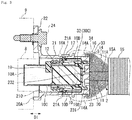
Figure 3 is a cross sectional view taken along line III-III ofFigure 1 , schematically showing a structure around an electric-wire; and -
Figure 4(a) is an isometric view showing a seal member from the front andFigure 4(b) is an isometric view showing the seal member from behind. - An embodiment of the present invention will be described below with reference to the accompanying drawings. An electrical connector 1 (plug type connector) shown in
Figure 1 andFigure 2 is provided with ahousing 10 from which two electric-wires are led out, ashell 20 for electromagnetic shielding, a seal member 3 (Figure 3 andFigures 4(a) and 4(b) ) positioned in thehousing 10, and a mating-portion seal 12 (Figure 3 ). - An end side from which the electric-
wires 11 are led out from the electrical connector 1 is defined as a "rear end", and the opposite end mated in a mating direction D1 to a mating connector (cap type connector) is defined as a "front end". The mating connector is typically assembled with a part of a case of a device (metal member 9 inFigure 3 ). - The electrical connector 1 and the mating connector are suitable for electrical connection of high voltage equipment, such as a PCU (Power Control Unit), installed on a vehicle. In order to reduce or eliminate the emission of electromagnetic noise outward from the equipment and/or the effect of electromagnetic noise from another piece of equipment, the electrical connector 1 and the mating connector have an electromagnetic shielding function.
- The electric-
wire 11 is a covered electric-wire having a core wire covered with an insulation layer. As shown inFigure 3 , the electric-wire 11 is covered with a braidedwire 14 for electromagnetic shielding. The braidedwire 14 includes interlaced metal wires and, if necessary, a reinforcing material. Two electric-wires 11 are positioned inside the braidedwire 14. An end portion of the braidedwire 14 is connected to an outer peripheral portion of theshell 20. Two electric-wires 11 and the braidedwire 14 are bundled together containing a waterproof layer and/or member (not shown), thereby constituting abundle cable 2. Thebundle cable 2 is typically accommodated in acorrugated tube 15 made of resin. Adistal end 15A of thecorrugated tube 15 is connected with a grommet 16 formed from an elastic material, such as rubber and/or elastomer. Adistal end 16A of the grommet 16 is retained on the outer peripheral portion of theshell 20 with abundling member 17. The grommet 16 covers the electric-wire 11 and thebraided wire 14 extending from thedistal end 15A of thecorrugated tube 15. - The shell 20 (
Figure 1 to Figure 3 ) made of metal encloses thehousing 10 and portions of a housing (hereinafter, referred to as mating housing 8 (Figure 3 )) of the mating connector which protrude out of the metal member 9 (Figure 3 ) . An end portion of the braidedwire 14 is electrically connected to an outer peripheral wall of theshell 20. By grounding theshell 20 to the case made of metal via themetal member 9, an electromagnetic shielding function is given to the electrical connector 1 and themating connector 8. - Each component of the electrical connector 1 will be described. The housing 10 (
Figures 1 and3 ) retains afemale terminal 18 made of a metal material. Thehousing 10 is formed from an insulating resin material. In the present embodiment, a two-position electrical connector 1 provided with twofemale terminals 18 is illustrated. The electrical connector 1 may be provided with a single position or three or more positions. Thefemale terminals 18 are connected with the respective electric-wires 11. - A
front end portion 10A of thehousing 10 is positioned inside the metal member 9 (Figure 3 ). The electric-wire 11 extends rearwardly from a rear end portion of thehousing 10. The electric-wire 11 extending out from thehousing 10 penetrates or extends through the seal member 3 (Figure 3 ). Thehousing 10 is formed with an accommodating portion 10B (Figure 3 ) for accommodating abase portion 30 of theseal member 3. In a bottom of the housing portion 10B, an opening is formed (not shown) through which theelectrical wires 11 extend. - On an outer
peripheral portion 10C of thehousing 10, a mating-portion seal 12 (Figure 3 ) formed in an annular shape is fitted. The mating-portion seal 12 is positioned in or around a stepped portion of the outerperipheral portion 10C, and aseal presser 19 prevents the mating-portion seal 12 from becoming detached frontwardly. When thehousing 10 is received inside themating housing 8, the mating-portion seal 12 elastically deforms radially between the outerperipheral portion 10C and an inner peripheral portion of themating housing 8. - The outer
peripheral portion 10C is formed with alock beam 10D (Figure 3 ) caught in or engaged with theshell 20. A part of thelock beam 10D is inserted into anengagement hole 21A of theshell 20. - The shell 20 (
Figure 1 to Figure 3 ) entirely encloses thehousing 10 except for thefront end portion 10A of thehousing 10. Theshell 20 is formed typically by die casting from a metal material, such as an aluminum alloy, a zinc alloy, or the like. The material of theshell 20 may be any material as long as it is conductive, and any suitable metal material, whether magnetic or nonmagnetic, may be used for theshell 20. For the material of the braided wire 14 (Figure 3 ), a conductive metal material can be used. - The
shell 20 is integrally provided with aside wall 21 enclosing the outerperipheral portion 10C of thehousing 10, anattachment portion 22 extending from a front end of theside wall 21, and a shell bottom or rear end portion 23 (Figure 2 ,Figure 3 ) at a rear end of theside wall 21. Themating housing 8 is inserted between theside wall 21 and the outerperipheral portion 10C of thehousing 10. - The front end of the
side wall 21 is open (Figure 1 ,Figure 3 ), and thefront end portion 10A of thehousing 10 protrudes from anopening 210 of theside wall 21. Theshell bottom portion 23 is located at the opposite side or end to theopening 210. The rear end of theside wall 21 is closed with theshell bottom portion 23. - The
side wall 21 is formed in a cylindrical shape. Anengagement hole 21A, into which a part of alock beam 10D is inserted, is formed on both upper and lower sides of theside wall 21 shown inFigure 3 . Theattachment portion 22 is fastened to themetal member 9 with abolt 24 which extends through theattachment portion 22. Contact with a predetermined contact pressure between a back surface of theattachment portion 22 and a surface of themetal member 9 fastened together ensures the required electrical connection between theshell 20 and themetal member 9 for electromagnetic shielding. - The shell bottom or rear portion 23 (
Figure 2 ,Figure 3 ) presses down or against theseal member 3 positioned in the rear end portion of thehousing 10 from behind. Since theshell bottom portion 23 is present, the electrical connector 1 is not provided with a seal cover for pressing against theseal member 3. Theshell bottom portion 23 is formed with aperipheral groove 231 for accommodating a part of theseal member 3. Theperipheral groove 231 extends along the entire periphery in the vicinity of a radial outer end or surface of theshell bottom portion 23. Aplug portion 232 enclosed with or encircled by theperipheral groove 231 is inserted into or positioned within a recessed portion 35 (Figure 4(b) ) of theseal member 3. The electric-wire 11 penetrates or extends through theplug portion 232. - In order to prevent entry of water, the electrical connector 1 of the present embodiment is provided with two seal members: the mating-
portion seal 12 and theseal member 3. These are formed from an elastic material, such as rubber and/or elastomer. In the present embodiment, the mating-portion seal 12 and theseal member 3 block entry of water into the housings (the inside of thehousing 10 and the mating housing 8) in which the terminals are housed. Furthermore, in order to prevent corrosion of aconnection location 14A of thebraided wire 14 to theshell 20, theseal member 3 and the grommet 16 block water from reaching theconnection location 14A of thebraided wire 14. - In order to block entry of water into the housings, it is necessary to individually prevent entry of water between the
housing 10 and themating housing 8 and between thehousing 10 and the electric-wire 11. The mating-portion seal 12 prevents entry of water into between thehousing 10 and themating housing 8. In order to block entry of water between thehousing 10 and the electric-wire 11, it is necessary to press the seal member against thehousing 10 around a region where the electric-wire 11 is positioned as well as to bring the seal member into close contact with the outerperipheral portion 11A of the electric-wire 11. Theseal member 3 bears the function of preventing entry of water between thehousing 10 and the electric-wire 11. - In the present embodiment, the
seal member 3 provided with ashell seal portion 33 pressed with or against theshell 20 prevents entry of water between theshell 20 and thehousing 10 covered with theshell 20. - As described above, the
seal member 3 is a multiple seal member having the function of preventing entry of water at a plurality of locations. The main characteristics of the present embodiment are that theshell 20 is provided with ashell bottom portion 23 and that theseal member 3 has portions situated at a plurality of locations required where water entry prevention is required. - With reference to
Figure 3 ,Figures 4(a) and 4(b) , theseal member 3 will be described. Theseal member 3 is sandwiched between the rear end portion of thehousing 10 and theshell bottom portion 23. The electric-wires 11 extend rearwardly from thehousing 10 and extend through theseal member 3. - The
seal member 3 is integrally provided with abase portion 30 interposed between thehousing 10 and theshell bottom portion 23, the same number of electric-wire seal portions 31 as the electric-wires 11, ahousing seal portion 32, theshell seal portion 33, and aperipheral wall 34. The plurality of electric-wire seal portions 31, thehousing seal portion 32, theshell seal portion 33, and theperipheral wall 34 all extend to thebase portion 30, and are integrally connected via thebase portion 30. - When the
housing 10 is inserted into theshell 20 with theseal member 3 accommodated inside theshell 20, thelock beam 10D of thehousing 10 enters theengagement hole 21A of theshell 20, and gets caught or engages in theside wall 21. Thereupon, theseal member 3 elastically deforms by being pressed between thehousing 10 and theshell 20, and consequently each of theseal portions seal member 3 comes into close contact with the counter-contact member or confronting surface. - The
base portion 30 is so positioned as to be perpendicular to the mating direction D1 between the bottom of the accommodating portion 10B of thehousing 10 and theplug portion 232 of theshell bottom portion 23. Thebase portion 30 has afront portion 30A (Figure 4(a) ) coming into contact with the bottom of the accommodating portion 10B, and arear portion 30B (Figure 4(b) ) coming into contact with theplug portion 232 of theshell bottom portion 23. Thefront portion 30A is pressed against a peripheral portion of the opening in the bottom of the accommodating portion 10B from which the electric-wires 11 extend. Thebase portion 30 is formed withseal holes 301 individually corresponding to the plurality of electric-wires 11. The seal holes 301 are formed along a direction (mating direction D1) connecting thefront portion 30A and therear portion 30B. The electric-wires 11 extend through the respective seal holes 301. The electric-wire seal portions 31 are equivalent to inner peripheral portions of the seal holes 301. The plurality of electric-wire seal portions 31 with which thebase portion 30 is provided collectively prevent entry of water around the plurality of electric-wires 11. Each electric-wire seal portion 31 includes one ormore ridges 31A extending along the circumference of theseal hole 301. Theridge 31A elastically deforms radially, thereby coming into close contact with the outerperipheral portion 11A of the electric-wire 11. - The
front portion 30A and therear portion 30B are formed with depressions having shapes suitable for facilitating elastic deformation at suitable locations in order to allow theseal member 3 to elastically deform sufficiently to enhance close contact with the counter-contact members. Specifically, agroove 302 located between the twoseal holes 301 in thefront portion 30A and/or a plurality of recessedportions 303 formed in therear portion 30B constitute such depressions. Except for these depressions and the positions of the seal holes 301, thefront portion 30A and therear portion 30B are flatly formed. - The
housing seal portion 32 is equivalent to anouter end portion 30C located on a radial outside of thebase portion 30, and is pressed against thehousing 10. Thehousing seal portion 32 includes one ormore ridges 32A extending along the periphery. Theridge 32A is pressed radially against an inner wall of the accommodating portion 10B in which thebase portion 30 is housed. - The electric-
wire seal portion 31, and thehousing seal portion 32 pressed against thehousing 10 at a location radially outside a region where the two electric-wires 11 penetrate can block water from entering thehousing 10 from the peripheries of the electric-wires 11 frontward and radially outward and further beyond an outer end of thehousing 10. - The
shell seal portion 33 is pressed against theshell bottom portion 23 at a location radially inside theconnection location 14A (Figure 3 ) of thebraided wire 14. Theshell seal portion 33 includes aridge 33A extending along the periphery. Theridge 33A is pressed radially with or against an outer peripheral portion of theplug portion 232 of theshell 20. - As shown in
Figure 4(b) , theshell seal portion 33 is equivalent to an inner peripheral portion of theperipheral wall 34 protruding rearwardly from thebase portion 30. Theperipheral wall 34, as shown inFigure 4(b) andFigure 3 , protrudes rearwardly from the vicinity of theouter end portion 30C (housing seal portion 32) of thebase portion 30, and extends along the entire periphery. When theplug portion 232 of theshell bottom portion 23 is inserted into the recessedportion 35 formed inside theperipheral wall 34, theperipheral wall 34 is accommodated in theperipheral groove 231 of theshell bottom portion 23. It is preferred that theperipheral wall 34 protrudes rearwardly from thebase portion 30 in the vicinity of and radially outside theouter end portion 30C of thebase portion 30. If so, an entire radial region of thebase portion 30 is pressed with theplug portion 232 inserted into theperipheral wall 34, and consequently thebase portion 30 can be sufficiently elastically deformed longitudinally (in the mating direction D1). Thereby, the close contact of the electric-wire seal portion 31 and thehousing seal portion 32 with their respective counter-contact members to be contacted can be enhanced. Furthermore, a proximal end of theperipheral wall 34 located radially outside theouter end portion 30C of thebase portion 30 comes into contact with thehousing 10, so that close contact between theshell seal portion 33 and the outer peripheral portion of theplug portion 232 can also be enhanced by elastically deforming theperipheral wall 34 between thehousing 10 and theshell bottom portion 23. - In the present embodiment described above, since the functions of preventing entry of water are integrated into one
seal member 3, the number of components is reduced. Prevention of entry of water is required around the electric-wires 11, between thehousing 10 and the electric-wires 11, and between theshell 20 and thehousing 10. Therefore, the manufacturing cost of the electrical connector 1, including the component cost and assembly cost, can be reduced. Usage of a plurality of seal members requires structures supporting them individually, whereas in the present embodiment it is only necessary to support theseal member 3 between thehousing 10 and theshell bottom portion 23, and therefore the present embodiment can contribute to size reduction of the electrical connector 1. - Since the
seal member 3 can be pressed down with or against theshell bottom portion 23 and theshell 20 is integrally provided with theside wall 21 and theshell bottom portion 23, a conventional seal cover is not required. This feature also contributes to reduction in the number of components and thus reduction in cost. Furthermore, since the seal cover is not present, a lock portion for catching the seal cover in theshell 20 is not required. Therefore, without being affected by the position of the lock portion of the seal cover, the position of theshell seal portion 33 coming into contact with theshell 20 can be set in the vicinity of the electric-wires 11 to a similar extent to thehousing seal portion 32. This allows theseal member 3 to be positioned from the positions of the electric-wires 11 to the position of thehousing seal portion 32 and/or theshell seal portion 33, namely, in a minimal region minimally required for prevention of entry of water, so that the size of theseal member 3 can be reduced. Since a region not contributing to prevention of entry of water, such as the lock portion of the seal cover, is eliminated, theseal member 3 is not expanded accordingly, and therefore a surface pressure of theseal member 3 pressed between theshell 20 and thehousing 10 can be more sufficiently secured as compared with the case that the electrical connector is provided with a seal cover. - As described above, according to the present embodiment, it is possible to achieve size reduction and cost reduction of the electrical connector 1 while keeping the function of preventing entry of water required for the electrical connector 1 and thereby securing the reliability of connection between the terminals.
- In addition to the above, adoption and/or elimination of the structures described in the above embodiment and/or an appropriate change to another structure can be made unless they depart from the present invention as claimed.
- For example, the
shell seal portion 33 of theseal member 3 may be formed on an outer peripheral portion of theperipheral wall 34. In that case, theshell seal portion 33 is pressed against an inner wall on an outer peripheral side of theperipheral groove 231 of theshell bottom portion 23. In addition, depending on the shapes of theshell 20 and theseal member 3, theshell seal member 33 may be pressed against both theside wall 21 and theshell bottom portion 23 of theshell 20. Furthermore, unless an interference with thelock beam 10D occurs, it is also possible for theperipheral wall 34 of theseal member 3 to protrude frontwardly from thebase portion 30. Theshell seal portion 33 can be formed on the inner peripheral portion or the outer peripheral portion of thatperipheral wall 34. -
- 1...electrical connector
- 2...bundle cable
- 3...seal member
- 8...mating housing (mating object)
- 9...metal member,
- 10...housing
- 10A...front end portion
- 10B...accommodating portion
- 10C...outer peripheral portion
- 10D...lock beam
- 11...electric-wire
- 11A...outer peripheral portion
- 12...mating-portion seal
- 14...braided wire
- 14A...connection location
- 15...corrugated tube
- 15A...distal end
- 16...grommet
- 16A...distal end
- 17...bundling member
- 18...female terminal
- 19...seal presser
- 20...shell
- 20A...front end
- 21...side wall
- 21A...engagement hole
- 210...opening
- 22...attachment portion
- 23...shell bottom portion
- 24...bolt
- 30...base portion
- 30A...front portion
- 30B... rear portion
- 30C...outer end portion
- 31...electric-wire seal portion
- 31A...ridge
- 32...housing seal portion
- 32A...ridge
- 33...shell seal portion
- 33A...ridge
- 34...peripheral wall
- 35...recessed portion
- 231...peripheral groove
- 232...plug portion (predetermined region of shell bottom portion)
- 301...seal hole
- 302...groove
- 303...recessed portion
- D1...mating direction
Claims (4)
- A seal member (3) used for an electrical connector (1), the seal member (3) being configured to be penetrated by an electric-wire (11) extending rearwardly from a housing (10) enclosed with a shell (20) made of metal, and to be pressed between the housing (10) and a bottom portion (23) of the shell (20), the seal member (3) integrally comprising:an electric-wire seal portion (31) configured to come into contact with an outer peripheral portion of the electric-wire (11);a housing seal portion (32) located on an outer end portion (30C) of a radial outside of a base portion (30) formed with the electric-wire seal portion (31), and configured to be pressed against the housing (10);a shell seal portion (33) configured to be pressed against at least the bottom portion (23) of the shell (20).
- The seal member (3) for an electrical connector (1) according to claim 1, further comprising:a peripheral wall (34) protruding frontwardly or rearwardly from the base portion (30), a predetermined region of the bottom portion (23) of the shell (20) being inserted into the peripheral wall (34), whereinthe shell seal portion (33) is equivalent to an inner peripheral portion or an outer peripheral portion of the peripheral wall (34).
- The seal member (3) for an electrical connector (1) according to claim 2, wherein
the peripheral wall (34) protrudes rearwardly from the base portion (23) in the vicinity of and radially outside the outer end portion (30C) of the base portion (30). - An electrical connector (1) comprising:a housing (10) configured to be mated with a mating object (8);a shell (20) made of metal and enclosing the housing (10); anda seal member (3) configured to be penetrated by an electric-wire (11) led out rearwardly from the housing (10), whereinthe shell (20) has a bottom portion (23) pressing the seal member (3) between the housing (10) and the bottom portion (23), andthe seal member (3) integrally comprises:an electric-wire seal portion (31) configured to come into contact with an outer peripheral portion of the electric-wire (11);a housing seal portion (32) located on an outer end portion (30C) of a radial outside of a base portion (30) formed with the electric-wire seal portion (31), and configured to be pressed against the housing (10);a shell seal portion (33) configured to be pressed against at least the bottom portion (23) of the shell (20).
Applications Claiming Priority (2)
| Application Number | Priority Date | Filing Date | Title |
|---|---|---|---|
| JP2017073439 | 2017-04-03 | ||
| JP2018037052A JP7072406B2 (en) | 2017-04-03 | 2018-03-02 | Sealing members and electrical connectors |
Publications (2)
| Publication Number | Publication Date |
|---|---|
| EP3386037A1 true EP3386037A1 (en) | 2018-10-10 |
| EP3386037B1 EP3386037B1 (en) | 2022-12-21 |
Family
ID=61868286
Family Applications (1)
| Application Number | Title | Priority Date | Filing Date |
|---|---|---|---|
| EP18165108.4A Active EP3386037B1 (en) | 2017-04-03 | 2018-03-29 | Electrical connector |
Country Status (3)
| Country | Link |
|---|---|
| US (1) | US10490931B2 (en) |
| EP (1) | EP3386037B1 (en) |
| CN (1) | CN108695641A (en) |
Cited By (1)
| Publication number | Priority date | Publication date | Assignee | Title |
|---|---|---|---|---|
| EP4315519A1 (en) | 2021-04-01 | 2024-02-07 | J.S.T. Corporation | Elastomer seal spring |
Families Citing this family (11)
| Publication number | Priority date | Publication date | Assignee | Title |
|---|---|---|---|---|
| US10116078B1 (en) * | 2017-08-01 | 2018-10-30 | Delphi Technologies, Inc. | High current compression blade connection system |
| JP2019033011A (en) * | 2017-08-09 | 2019-02-28 | 矢崎総業株式会社 | Mounting structure for shield connector directly mounted on apparatus |
| JP6939612B2 (en) * | 2018-02-01 | 2021-09-22 | 住友電装株式会社 | Waterproof connector |
| JP6897621B2 (en) * | 2018-03-30 | 2021-06-30 | 株式会社オートネットワーク技術研究所 | Wire harness |
| JP7156167B2 (en) * | 2019-05-14 | 2022-10-19 | 住友電装株式会社 | connector |
| JP7256155B2 (en) * | 2020-09-30 | 2023-04-11 | 矢崎総業株式会社 | connector |
| CN213782344U (en) * | 2020-11-06 | 2021-07-23 | 深圳市大疆创新科技有限公司 | Wire end connector, connector assembly and movable platform |
| CN112582842B (en) * | 2021-01-06 | 2022-03-25 | 山东恒东实业集团有限公司 | Plug connecting device capable of performing overcurrent protection on outdoor electric equipment |
| EP4080687B1 (en) * | 2021-04-21 | 2025-08-27 | Rosenberger Hochfrequenztechnik GmbH & Co. KG | Connector assembly and connector |
| JP7307125B2 (en) * | 2021-07-14 | 2023-07-11 | 矢崎総業株式会社 | Water stop structure and water stop parts for shielded cables |
| US11757228B2 (en) * | 2021-08-25 | 2023-09-12 | Avertronics Inc. | Connector used in underwater environments |
Citations (4)
| Publication number | Priority date | Publication date | Assignee | Title |
|---|---|---|---|---|
| JP2010153072A (en) | 2008-12-24 | 2010-07-08 | Sumitomo Wiring Syst Ltd | Waterproof connector |
| US20140120767A1 (en) * | 2012-10-25 | 2014-05-01 | Sumitomo Wiring Systems, Ltd. | Shield connector |
| US20160072211A1 (en) * | 2013-04-24 | 2016-03-10 | Yazaki Corporation | Electric Wire Connector Structure |
| US9431756B2 (en) * | 2014-06-24 | 2016-08-30 | Japan Aviation Electronics Industry, Limited | Waterproof connector |
Family Cites Families (45)
| Publication number | Priority date | Publication date | Assignee | Title |
|---|---|---|---|---|
| US4030797A (en) * | 1975-06-11 | 1977-06-21 | International Telephone And Telegraph Corporation | Electrical connector |
| US4349241A (en) * | 1980-05-09 | 1982-09-14 | Bunker Ramo Corporation | Electrical connector assembly having enhanced EMI shielding |
| US4447103A (en) * | 1981-12-28 | 1984-05-08 | The Bendix Corporation | Moisture seal for a separable electrical connection |
| US4421373A (en) * | 1981-12-28 | 1983-12-20 | The Bendix Corporation | Electrical connector having means for sealing against moisture |
| US4521064A (en) * | 1983-05-11 | 1985-06-04 | Allied Corporation | Electrical connector having a moisture seal |
| US5057030A (en) * | 1990-07-02 | 1991-10-15 | Itt Corporation | Grommet/seal member for a connector assembly |
| US5092794A (en) * | 1990-12-24 | 1992-03-03 | Molex Incorporated | Shielded electrical connector |
| JP2768626B2 (en) * | 1993-11-10 | 1998-06-25 | 住友電装株式会社 | Waterproof connector |
| DE4418004C2 (en) * | 1994-05-21 | 1998-08-06 | Delphi Automotive Systems Gmbh | Electrical connection, in particular for motor vehicles |
| JPH08180928A (en) * | 1994-10-24 | 1996-07-12 | Yazaki Corp | Waterproof connector |
| JPH09129304A (en) | 1995-11-02 | 1997-05-16 | Sumitomo Wiring Syst Ltd | Sealing member holding structure in water-proof connector |
| US6475008B1 (en) * | 1996-06-24 | 2002-11-05 | The United States Of America As Represented By The Secretary Of The Navy | Underwater mateable electrical connector with anti-hydrolock feature |
| US5720629A (en) * | 1996-10-16 | 1998-02-24 | The Whitaker Corporation | Sealed electrical connector |
| JP3627209B2 (en) * | 1999-04-07 | 2005-03-09 | 矢崎総業株式会社 | Shield connector structure |
| JP3946452B2 (en) * | 2001-02-22 | 2007-07-18 | 矢崎総業株式会社 | Waterproof connector |
| JP4348879B2 (en) * | 2001-07-17 | 2009-10-21 | 住友電装株式会社 | Connector device for equipment |
| US6705894B1 (en) * | 2003-01-02 | 2004-03-16 | Molex Incorporated | Shielded electrical connector |
| JP2004327169A (en) * | 2003-04-23 | 2004-11-18 | Yazaki Corp | Packing and connector with packing |
| US7083471B2 (en) * | 2003-06-18 | 2006-08-01 | Autonetworks Technologies, Ltd. | Connecting structure of connector, shield connector and lever type connector |
| US7097500B2 (en) * | 2004-06-25 | 2006-08-29 | John Mezzalingua Associates, Inc. | Nut seal assembly for coaxial cable system components |
| JP4559369B2 (en) * | 2006-02-03 | 2010-10-06 | 矢崎総業株式会社 | Packing mounting structure |
| JP4970220B2 (en) * | 2007-11-16 | 2012-07-04 | 矢崎総業株式会社 | Shield connector |
| JP5046043B2 (en) * | 2008-07-10 | 2012-10-10 | 住友電装株式会社 | connector |
| JP2011048949A (en) * | 2009-08-25 | 2011-03-10 | Sumitomo Wiring Syst Ltd | Shield connector apparatus |
| JP2013516032A (en) * | 2009-12-24 | 2013-05-09 | エフシーアイ・オートモティヴ・ホールディング | Electrical connector assembly |
| JP5531940B2 (en) * | 2010-12-13 | 2014-06-25 | 住友電装株式会社 | Waterproof connector |
| WO2012124801A1 (en) * | 2011-03-17 | 2012-09-20 | 株式会社オートネットワーク技術研究所 | Connector |
| US9318849B2 (en) * | 2011-04-14 | 2016-04-19 | Yazaki Corporation | Shielded connector |
| JP5917013B2 (en) * | 2011-04-19 | 2016-05-11 | 住友電装株式会社 | Shield connector |
| US8523609B2 (en) * | 2011-06-13 | 2013-09-03 | Tyco Electronics Corporation | Photovoltaic connector assembly |
| JP5864239B2 (en) * | 2011-12-08 | 2016-02-17 | 矢崎総業株式会社 | Connector and connector manufacturing method |
| JP2014007133A (en) * | 2012-05-28 | 2014-01-16 | Auto Network Gijutsu Kenkyusho:Kk | Connector |
| JP2014086349A (en) * | 2012-10-25 | 2014-05-12 | Sumitomo Wiring Syst Ltd | Connector |
| JP6234034B2 (en) * | 2013-02-20 | 2017-11-22 | 矢崎総業株式会社 | Shield connector structure |
| JP6130722B2 (en) * | 2013-04-26 | 2017-05-17 | 矢崎総業株式会社 | Terminal connection structure |
| DE112014002216T5 (en) * | 2013-04-30 | 2016-01-28 | Yazaki Corporation | Interconnects |
| JP6125891B2 (en) * | 2013-05-07 | 2017-05-10 | 矢崎総業株式会社 | Terminal bracket holding structure |
| JP2015005422A (en) * | 2013-06-21 | 2015-01-08 | 矢崎総業株式会社 | connector |
| DE102013112115A1 (en) * | 2013-11-04 | 2015-05-07 | Phoenix Contact Gmbh & Co. Kg | Bridge module for a component assembly system |
| JP6283289B2 (en) * | 2014-09-05 | 2018-02-21 | 矢崎総業株式会社 | Seal member |
| JP2016105350A (en) * | 2014-12-01 | 2016-06-09 | 住友電装株式会社 | Waterproof connector |
| JP6492929B2 (en) * | 2015-04-23 | 2019-04-03 | 住友電装株式会社 | connector |
| FR3051080B1 (en) * | 2016-05-09 | 2022-07-22 | Delphi Int Operations Luxembourg Sarl | CONNECTION ASSEMBLY AND METHOD OF ASSEMBLING THIS CONNECTION ASSEMBLY |
| JP2017208193A (en) * | 2016-05-17 | 2017-11-24 | 日本圧着端子製造株式会社 | Waterproof connector |
| JP6749232B2 (en) * | 2016-12-27 | 2020-09-02 | ホシデン株式会社 | Receptacle connector and camera unit |
-
2018
- 2018-03-29 CN CN201810272038.2A patent/CN108695641A/en active Pending
- 2018-03-29 EP EP18165108.4A patent/EP3386037B1/en active Active
- 2018-04-03 US US15/944,090 patent/US10490931B2/en active Active
Patent Citations (4)
| Publication number | Priority date | Publication date | Assignee | Title |
|---|---|---|---|---|
| JP2010153072A (en) | 2008-12-24 | 2010-07-08 | Sumitomo Wiring Syst Ltd | Waterproof connector |
| US20140120767A1 (en) * | 2012-10-25 | 2014-05-01 | Sumitomo Wiring Systems, Ltd. | Shield connector |
| US20160072211A1 (en) * | 2013-04-24 | 2016-03-10 | Yazaki Corporation | Electric Wire Connector Structure |
| US9431756B2 (en) * | 2014-06-24 | 2016-08-30 | Japan Aviation Electronics Industry, Limited | Waterproof connector |
Cited By (2)
| Publication number | Priority date | Publication date | Assignee | Title |
|---|---|---|---|---|
| EP4315519A1 (en) | 2021-04-01 | 2024-02-07 | J.S.T. Corporation | Elastomer seal spring |
| EP4315519A4 (en) * | 2021-04-01 | 2025-03-05 | J.S.T. Corporation | ELASTOMER SEALING SPRING |
Also Published As
| Publication number | Publication date |
|---|---|
| CN108695641A (en) | 2018-10-23 |
| US20180287293A1 (en) | 2018-10-04 |
| EP3386037B1 (en) | 2022-12-21 |
| US10490931B2 (en) | 2019-11-26 |
Similar Documents
| Publication | Publication Date | Title |
|---|---|---|
| EP3386037B1 (en) | Electrical connector | |
| EP3382820B1 (en) | Seal member and electrical connector | |
| EP2693574B1 (en) | Shield connector | |
| CN110383591B (en) | Shielding terminal and shielding connector | |
| US7618286B2 (en) | Shield connector | |
| EP2355267B1 (en) | Shield connector | |
| KR101938932B1 (en) | Electrical connector | |
| CN113904162B (en) | Connector | |
| JP4909793B2 (en) | Shield connector | |
| US7275960B2 (en) | Wire harness-side shield connector | |
| US8403698B2 (en) | Cable assembly with an improved grounding device | |
| EP3565066B1 (en) | Shielded cable penetrable component with boundary contact | |
| CN113540900B (en) | High voltage shielded connector | |
| US7044795B2 (en) | Miniature, shielded electrical connector with strain relief | |
| JP5170013B2 (en) | Shield connector | |
| US11735335B2 (en) | Water-stop structure and water-stop parts for shielded cable | |
| JP5229580B2 (en) | Shield connector | |
| KR100800789B1 (en) | Shield connector | |
| JP2014112484A (en) | Waterproof connector | |
| CN114041247A (en) | Connector with a locking member | |
| JP7072406B2 (en) | Sealing members and electrical connectors | |
| WO2016134457A1 (en) | Sealing grommet assembly and installation method therefor | |
| JP7827674B2 (en) | connector | |
| WO2024048238A1 (en) | Connector | |
| JP2015011946A (en) | Shield connector |
Legal Events
| Date | Code | Title | Description |
|---|---|---|---|
| PUAI | Public reference made under article 153(3) epc to a published international application that has entered the european phase |
Free format text: ORIGINAL CODE: 0009012 |
|
| STAA | Information on the status of an ep patent application or granted ep patent |
Free format text: STATUS: THE APPLICATION HAS BEEN PUBLISHED |
|
| AK | Designated contracting states |
Kind code of ref document: A1 Designated state(s): AL AT BE BG CH CY CZ DE DK EE ES FI FR GB GR HR HU IE IS IT LI LT LU LV MC MK MT NL NO PL PT RO RS SE SI SK SM TR |
|
| AX | Request for extension of the european patent |
Extension state: BA ME |
|
| STAA | Information on the status of an ep patent application or granted ep patent |
Free format text: STATUS: REQUEST FOR EXAMINATION WAS MADE |
|
| 17P | Request for examination filed |
Effective date: 20190307 |
|
| RBV | Designated contracting states (corrected) |
Designated state(s): AL AT BE BG CH CY CZ DE DK EE ES FI FR GB GR HR HU IE IS IT LI LT LU LV MC MK MT NL NO PL PT RO RS SE SI SK SM TR |
|
| STAA | Information on the status of an ep patent application or granted ep patent |
Free format text: STATUS: EXAMINATION IS IN PROGRESS |
|
| 17Q | First examination report despatched |
Effective date: 20200324 |
|
| RIC1 | Information provided on ipc code assigned before grant |
Ipc: H01R 13/621 20060101ALN20201123BHEP Ipc: H01R 13/52 20060101AFI20201123BHEP Ipc: H01R 13/6593 20110101ALN20201123BHEP Ipc: H01R 13/6596 20110101ALN20201123BHEP |
|
| RIC1 | Information provided on ipc code assigned before grant |
Ipc: H01R 13/621 20060101ALN20220512BHEP Ipc: H01R 13/6596 20110101ALN20220512BHEP Ipc: H01R 13/6593 20110101ALN20220512BHEP Ipc: H01R 13/52 20060101AFI20220512BHEP |
|
| GRAP | Despatch of communication of intention to grant a patent |
Free format text: ORIGINAL CODE: EPIDOSNIGR1 |
|
| STAA | Information on the status of an ep patent application or granted ep patent |
Free format text: STATUS: GRANT OF PATENT IS INTENDED |
|
| RIC1 | Information provided on ipc code assigned before grant |
Ipc: H01R 13/621 20060101ALN20220610BHEP Ipc: H01R 13/6596 20110101ALN20220610BHEP Ipc: H01R 13/6593 20110101ALN20220610BHEP Ipc: H01R 13/52 20060101AFI20220610BHEP |
|
| RIC1 | Information provided on ipc code assigned before grant |
Ipc: H01R 13/621 20060101ALN20220628BHEP Ipc: H01R 13/6596 20110101ALN20220628BHEP Ipc: H01R 13/6593 20110101ALN20220628BHEP Ipc: H01R 13/52 20060101AFI20220628BHEP |
|
| INTG | Intention to grant announced |
Effective date: 20220711 |
|
| GRAS | Grant fee paid |
Free format text: ORIGINAL CODE: EPIDOSNIGR3 |
|
| GRAA | (expected) grant |
Free format text: ORIGINAL CODE: 0009210 |
|
| STAA | Information on the status of an ep patent application or granted ep patent |
Free format text: STATUS: THE PATENT HAS BEEN GRANTED |
|
| AK | Designated contracting states |
Kind code of ref document: B1 Designated state(s): AL AT BE BG CH CY CZ DE DK EE ES FI FR GB GR HR HU IE IS IT LI LT LU LV MC MK MT NL NO PL PT RO RS SE SI SK SM TR |
|
| REG | Reference to a national code |
Ref country code: GB Ref legal event code: FG4D |
|
| REG | Reference to a national code |
Ref country code: CH Ref legal event code: EP |
|
| REG | Reference to a national code |
Ref country code: DE Ref legal event code: R096 Ref document number: 602018044407 Country of ref document: DE |
|
| REG | Reference to a national code |
Ref country code: AT Ref legal event code: REF Ref document number: 1539608 Country of ref document: AT Kind code of ref document: T Effective date: 20230115 |
|
| REG | Reference to a national code |
Ref country code: IE Ref legal event code: FG4D |
|
| REG | Reference to a national code |
Ref country code: LT Ref legal event code: MG9D |
|
| REG | Reference to a national code |
Ref country code: NL Ref legal event code: MP Effective date: 20221221 |
|
| PG25 | Lapsed in a contracting state [announced via postgrant information from national office to epo] |
Ref country code: SE Free format text: LAPSE BECAUSE OF FAILURE TO SUBMIT A TRANSLATION OF THE DESCRIPTION OR TO PAY THE FEE WITHIN THE PRESCRIBED TIME-LIMIT Effective date: 20221221 Ref country code: NO Free format text: LAPSE BECAUSE OF FAILURE TO SUBMIT A TRANSLATION OF THE DESCRIPTION OR TO PAY THE FEE WITHIN THE PRESCRIBED TIME-LIMIT Effective date: 20230321 Ref country code: LT Free format text: LAPSE BECAUSE OF FAILURE TO SUBMIT A TRANSLATION OF THE DESCRIPTION OR TO PAY THE FEE WITHIN THE PRESCRIBED TIME-LIMIT Effective date: 20221221 Ref country code: FI Free format text: LAPSE BECAUSE OF FAILURE TO SUBMIT A TRANSLATION OF THE DESCRIPTION OR TO PAY THE FEE WITHIN THE PRESCRIBED TIME-LIMIT Effective date: 20221221 |
|
| REG | Reference to a national code |
Ref country code: AT Ref legal event code: MK05 Ref document number: 1539608 Country of ref document: AT Kind code of ref document: T Effective date: 20221221 |
|
| PG25 | Lapsed in a contracting state [announced via postgrant information from national office to epo] |
Ref country code: RS Free format text: LAPSE BECAUSE OF FAILURE TO SUBMIT A TRANSLATION OF THE DESCRIPTION OR TO PAY THE FEE WITHIN THE PRESCRIBED TIME-LIMIT Effective date: 20221221 Ref country code: LV Free format text: LAPSE BECAUSE OF FAILURE TO SUBMIT A TRANSLATION OF THE DESCRIPTION OR TO PAY THE FEE WITHIN THE PRESCRIBED TIME-LIMIT Effective date: 20221221 Ref country code: HR Free format text: LAPSE BECAUSE OF FAILURE TO SUBMIT A TRANSLATION OF THE DESCRIPTION OR TO PAY THE FEE WITHIN THE PRESCRIBED TIME-LIMIT Effective date: 20221221 Ref country code: GR Free format text: LAPSE BECAUSE OF FAILURE TO SUBMIT A TRANSLATION OF THE DESCRIPTION OR TO PAY THE FEE WITHIN THE PRESCRIBED TIME-LIMIT Effective date: 20230322 |
|
| PG25 | Lapsed in a contracting state [announced via postgrant information from national office to epo] |
Ref country code: NL Free format text: LAPSE BECAUSE OF FAILURE TO SUBMIT A TRANSLATION OF THE DESCRIPTION OR TO PAY THE FEE WITHIN THE PRESCRIBED TIME-LIMIT Effective date: 20221221 |
|
| PG25 | Lapsed in a contracting state [announced via postgrant information from national office to epo] |
Ref country code: SM Free format text: LAPSE BECAUSE OF FAILURE TO SUBMIT A TRANSLATION OF THE DESCRIPTION OR TO PAY THE FEE WITHIN THE PRESCRIBED TIME-LIMIT Effective date: 20221221 Ref country code: RO Free format text: LAPSE BECAUSE OF FAILURE TO SUBMIT A TRANSLATION OF THE DESCRIPTION OR TO PAY THE FEE WITHIN THE PRESCRIBED TIME-LIMIT Effective date: 20221221 Ref country code: PT Free format text: LAPSE BECAUSE OF FAILURE TO SUBMIT A TRANSLATION OF THE DESCRIPTION OR TO PAY THE FEE WITHIN THE PRESCRIBED TIME-LIMIT Effective date: 20230421 Ref country code: ES Free format text: LAPSE BECAUSE OF FAILURE TO SUBMIT A TRANSLATION OF THE DESCRIPTION OR TO PAY THE FEE WITHIN THE PRESCRIBED TIME-LIMIT Effective date: 20221221 Ref country code: EE Free format text: LAPSE BECAUSE OF FAILURE TO SUBMIT A TRANSLATION OF THE DESCRIPTION OR TO PAY THE FEE WITHIN THE PRESCRIBED TIME-LIMIT Effective date: 20221221 Ref country code: CZ Free format text: LAPSE BECAUSE OF FAILURE TO SUBMIT A TRANSLATION OF THE DESCRIPTION OR TO PAY THE FEE WITHIN THE PRESCRIBED TIME-LIMIT Effective date: 20221221 Ref country code: AT Free format text: LAPSE BECAUSE OF FAILURE TO SUBMIT A TRANSLATION OF THE DESCRIPTION OR TO PAY THE FEE WITHIN THE PRESCRIBED TIME-LIMIT Effective date: 20221221 |
|
| PG25 | Lapsed in a contracting state [announced via postgrant information from national office to epo] |
Ref country code: SK Free format text: LAPSE BECAUSE OF FAILURE TO SUBMIT A TRANSLATION OF THE DESCRIPTION OR TO PAY THE FEE WITHIN THE PRESCRIBED TIME-LIMIT Effective date: 20221221 Ref country code: PL Free format text: LAPSE BECAUSE OF FAILURE TO SUBMIT A TRANSLATION OF THE DESCRIPTION OR TO PAY THE FEE WITHIN THE PRESCRIBED TIME-LIMIT Effective date: 20221221 Ref country code: IS Free format text: LAPSE BECAUSE OF FAILURE TO SUBMIT A TRANSLATION OF THE DESCRIPTION OR TO PAY THE FEE WITHIN THE PRESCRIBED TIME-LIMIT Effective date: 20230421 Ref country code: AL Free format text: LAPSE BECAUSE OF FAILURE TO SUBMIT A TRANSLATION OF THE DESCRIPTION OR TO PAY THE FEE WITHIN THE PRESCRIBED TIME-LIMIT Effective date: 20221221 |
|
| REG | Reference to a national code |
Ref country code: DE Ref legal event code: R097 Ref document number: 602018044407 Country of ref document: DE |
|
| PLBE | No opposition filed within time limit |
Free format text: ORIGINAL CODE: 0009261 |
|
| STAA | Information on the status of an ep patent application or granted ep patent |
Free format text: STATUS: NO OPPOSITION FILED WITHIN TIME LIMIT |
|
| PG25 | Lapsed in a contracting state [announced via postgrant information from national office to epo] |
Ref country code: MC Free format text: LAPSE BECAUSE OF FAILURE TO SUBMIT A TRANSLATION OF THE DESCRIPTION OR TO PAY THE FEE WITHIN THE PRESCRIBED TIME-LIMIT Effective date: 20221221 Ref country code: DK Free format text: LAPSE BECAUSE OF FAILURE TO SUBMIT A TRANSLATION OF THE DESCRIPTION OR TO PAY THE FEE WITHIN THE PRESCRIBED TIME-LIMIT Effective date: 20221221 |
|
| REG | Reference to a national code |
Ref country code: CH Ref legal event code: PL |
|
| 26N | No opposition filed |
Effective date: 20230922 |
|
| GBPC | Gb: european patent ceased through non-payment of renewal fee |
Effective date: 20230329 |
|
| REG | Reference to a national code |
Ref country code: BE Ref legal event code: MM Effective date: 20230331 |
|
| PG25 | Lapsed in a contracting state [announced via postgrant information from national office to epo] |
Ref country code: LU Free format text: LAPSE BECAUSE OF NON-PAYMENT OF DUE FEES Effective date: 20230329 |
|
| REG | Reference to a national code |
Ref country code: IE Ref legal event code: MM4A |
|
| PG25 | Lapsed in a contracting state [announced via postgrant information from national office to epo] |
Ref country code: GB Free format text: LAPSE BECAUSE OF NON-PAYMENT OF DUE FEES Effective date: 20230329 |
|
| PG25 | Lapsed in a contracting state [announced via postgrant information from national office to epo] |
Ref country code: SI Free format text: LAPSE BECAUSE OF FAILURE TO SUBMIT A TRANSLATION OF THE DESCRIPTION OR TO PAY THE FEE WITHIN THE PRESCRIBED TIME-LIMIT Effective date: 20221221 Ref country code: LI Free format text: LAPSE BECAUSE OF NON-PAYMENT OF DUE FEES Effective date: 20230331 Ref country code: IE Free format text: LAPSE BECAUSE OF NON-PAYMENT OF DUE FEES Effective date: 20230329 Ref country code: GB Free format text: LAPSE BECAUSE OF NON-PAYMENT OF DUE FEES Effective date: 20230329 Ref country code: CH Free format text: LAPSE BECAUSE OF NON-PAYMENT OF DUE FEES Effective date: 20230331 |
|
| PG25 | Lapsed in a contracting state [announced via postgrant information from national office to epo] |
Ref country code: BE Free format text: LAPSE BECAUSE OF NON-PAYMENT OF DUE FEES Effective date: 20230331 |
|
| PG25 | Lapsed in a contracting state [announced via postgrant information from national office to epo] |
Ref country code: IT Free format text: LAPSE BECAUSE OF FAILURE TO SUBMIT A TRANSLATION OF THE DESCRIPTION OR TO PAY THE FEE WITHIN THE PRESCRIBED TIME-LIMIT Effective date: 20221221 |
|
| PG25 | Lapsed in a contracting state [announced via postgrant information from national office to epo] |
Ref country code: BG Free format text: LAPSE BECAUSE OF FAILURE TO SUBMIT A TRANSLATION OF THE DESCRIPTION OR TO PAY THE FEE WITHIN THE PRESCRIBED TIME-LIMIT Effective date: 20221221 |
|
| PG25 | Lapsed in a contracting state [announced via postgrant information from national office to epo] |
Ref country code: BG Free format text: LAPSE BECAUSE OF FAILURE TO SUBMIT A TRANSLATION OF THE DESCRIPTION OR TO PAY THE FEE WITHIN THE PRESCRIBED TIME-LIMIT Effective date: 20221221 |
|
| PG25 | Lapsed in a contracting state [announced via postgrant information from national office to epo] |
Ref country code: CY Free format text: LAPSE BECAUSE OF FAILURE TO SUBMIT A TRANSLATION OF THE DESCRIPTION OR TO PAY THE FEE WITHIN THE PRESCRIBED TIME-LIMIT; INVALID AB INITIO Effective date: 20180329 |
|
| PG25 | Lapsed in a contracting state [announced via postgrant information from national office to epo] |
Ref country code: HU Free format text: LAPSE BECAUSE OF FAILURE TO SUBMIT A TRANSLATION OF THE DESCRIPTION OR TO PAY THE FEE WITHIN THE PRESCRIBED TIME-LIMIT; INVALID AB INITIO Effective date: 20180329 |
|
| PG25 | Lapsed in a contracting state [announced via postgrant information from national office to epo] |
Ref country code: TR Free format text: LAPSE BECAUSE OF FAILURE TO SUBMIT A TRANSLATION OF THE DESCRIPTION OR TO PAY THE FEE WITHIN THE PRESCRIBED TIME-LIMIT Effective date: 20221221 |
|
| PGFP | Annual fee paid to national office [announced via postgrant information from national office to epo] |
Ref country code: FR Payment date: 20251231 Year of fee payment: 9 |
|
| PGFP | Annual fee paid to national office [announced via postgrant information from national office to epo] |
Ref country code: DE Payment date: 20260102 Year of fee payment: 9 |