EP3386025A1 - Lithium-ion battery cell and lithium-ion battery - Google Patents
Lithium-ion battery cell and lithium-ion battery Download PDFInfo
- Publication number
- EP3386025A1 EP3386025A1 EP16869830.6A EP16869830A EP3386025A1 EP 3386025 A1 EP3386025 A1 EP 3386025A1 EP 16869830 A EP16869830 A EP 16869830A EP 3386025 A1 EP3386025 A1 EP 3386025A1
- Authority
- EP
- European Patent Office
- Prior art keywords
- positive
- negative
- lugs
- lug
- lithium
- Prior art date
- Legal status (The legal status is an assumption and is not a legal conclusion. Google has not performed a legal analysis and makes no representation as to the accuracy of the status listed.)
- Granted
Links
Images


Classifications
-
- H—ELECTRICITY
- H01—ELECTRIC ELEMENTS
- H01M—PROCESSES OR MEANS, e.g. BATTERIES, FOR THE DIRECT CONVERSION OF CHEMICAL ENERGY INTO ELECTRICAL ENERGY
- H01M50/00—Constructional details or processes of manufacture of the non-active parts of electrochemical cells other than fuel cells, e.g. hybrid cells
- H01M50/50—Current conducting connections for cells or batteries
- H01M50/531—Electrode connections inside a battery casing
- H01M50/538—Connection of several leads or tabs of wound or folded electrode stacks
-
- H—ELECTRICITY
- H01—ELECTRIC ELEMENTS
- H01M—PROCESSES OR MEANS, e.g. BATTERIES, FOR THE DIRECT CONVERSION OF CHEMICAL ENERGY INTO ELECTRICAL ENERGY
- H01M10/00—Secondary cells; Manufacture thereof
- H01M10/04—Construction or manufacture in general
- H01M10/0431—Cells with wound or folded electrodes
-
- H—ELECTRICITY
- H01—ELECTRIC ELEMENTS
- H01M—PROCESSES OR MEANS, e.g. BATTERIES, FOR THE DIRECT CONVERSION OF CHEMICAL ENERGY INTO ELECTRICAL ENERGY
- H01M10/00—Secondary cells; Manufacture thereof
- H01M10/04—Construction or manufacture in general
- H01M10/0459—Cells or batteries with folded separator between plate-like electrodes
-
- H—ELECTRICITY
- H01—ELECTRIC ELEMENTS
- H01M—PROCESSES OR MEANS, e.g. BATTERIES, FOR THE DIRECT CONVERSION OF CHEMICAL ENERGY INTO ELECTRICAL ENERGY
- H01M10/00—Secondary cells; Manufacture thereof
- H01M10/05—Accumulators with non-aqueous electrolyte
- H01M10/052—Li-accumulators
- H01M10/0525—Rocking-chair batteries, i.e. batteries with lithium insertion or intercalation in both electrodes; Lithium-ion batteries
-
- H—ELECTRICITY
- H01—ELECTRIC ELEMENTS
- H01M—PROCESSES OR MEANS, e.g. BATTERIES, FOR THE DIRECT CONVERSION OF CHEMICAL ENERGY INTO ELECTRICAL ENERGY
- H01M10/00—Secondary cells; Manufacture thereof
- H01M10/05—Accumulators with non-aqueous electrolyte
- H01M10/058—Construction or manufacture
- H01M10/0587—Construction or manufacture of accumulators having only wound construction elements, i.e. wound positive electrodes, wound negative electrodes and wound separators
-
- H—ELECTRICITY
- H01—ELECTRIC ELEMENTS
- H01M—PROCESSES OR MEANS, e.g. BATTERIES, FOR THE DIRECT CONVERSION OF CHEMICAL ENERGY INTO ELECTRICAL ENERGY
- H01M4/00—Electrodes
- H01M4/02—Electrodes composed of, or comprising, active material
-
- H—ELECTRICITY
- H01—ELECTRIC ELEMENTS
- H01M—PROCESSES OR MEANS, e.g. BATTERIES, FOR THE DIRECT CONVERSION OF CHEMICAL ENERGY INTO ELECTRICAL ENERGY
- H01M50/00—Constructional details or processes of manufacture of the non-active parts of electrochemical cells other than fuel cells, e.g. hybrid cells
- H01M50/50—Current conducting connections for cells or batteries
- H01M50/531—Electrode connections inside a battery casing
- H01M50/534—Electrode connections inside a battery casing characterised by the material of the leads or tabs
-
- H—ELECTRICITY
- H01—ELECTRIC ELEMENTS
- H01M—PROCESSES OR MEANS, e.g. BATTERIES, FOR THE DIRECT CONVERSION OF CHEMICAL ENERGY INTO ELECTRICAL ENERGY
- H01M4/00—Electrodes
- H01M4/02—Electrodes composed of, or comprising, active material
- H01M2004/026—Electrodes composed of, or comprising, active material characterised by the polarity
- H01M2004/028—Positive electrodes
-
- H—ELECTRICITY
- H01—ELECTRIC ELEMENTS
- H01M—PROCESSES OR MEANS, e.g. BATTERIES, FOR THE DIRECT CONVERSION OF CHEMICAL ENERGY INTO ELECTRICAL ENERGY
- H01M2220/00—Batteries for particular applications
- H01M2220/20—Batteries in motive systems, e.g. vehicle, ship, plane
-
- Y—GENERAL TAGGING OF NEW TECHNOLOGICAL DEVELOPMENTS; GENERAL TAGGING OF CROSS-SECTIONAL TECHNOLOGIES SPANNING OVER SEVERAL SECTIONS OF THE IPC; TECHNICAL SUBJECTS COVERED BY FORMER USPC CROSS-REFERENCE ART COLLECTIONS [XRACs] AND DIGESTS
- Y02—TECHNOLOGIES OR APPLICATIONS FOR MITIGATION OR ADAPTATION AGAINST CLIMATE CHANGE
- Y02E—REDUCTION OF GREENHOUSE GAS [GHG] EMISSIONS, RELATED TO ENERGY GENERATION, TRANSMISSION OR DISTRIBUTION
- Y02E60/00—Enabling technologies; Technologies with a potential or indirect contribution to GHG emissions mitigation
- Y02E60/10—Energy storage using batteries
-
- Y—GENERAL TAGGING OF NEW TECHNOLOGICAL DEVELOPMENTS; GENERAL TAGGING OF CROSS-SECTIONAL TECHNOLOGIES SPANNING OVER SEVERAL SECTIONS OF THE IPC; TECHNICAL SUBJECTS COVERED BY FORMER USPC CROSS-REFERENCE ART COLLECTIONS [XRACs] AND DIGESTS
- Y02—TECHNOLOGIES OR APPLICATIONS FOR MITIGATION OR ADAPTATION AGAINST CLIMATE CHANGE
- Y02P—CLIMATE CHANGE MITIGATION TECHNOLOGIES IN THE PRODUCTION OR PROCESSING OF GOODS
- Y02P70/00—Climate change mitigation technologies in the production process for final industrial or consumer products
- Y02P70/50—Manufacturing or production processes characterised by the final manufactured product
Definitions
- the present disclosure relates to the technical field of lithium-ion batteries, in particular to a lithium-ion battery cell and a lithium-ion battery.
- Power lithium-ion batteries mainly include types of cylindrical, laminated aluminum plastic film, winding square (aluminum cased), laminated square and the like.
- a process for a cylindrical battery is mature, the cylindrical battery has a high consistency and may be designed to have a high rate.
- capacity of the cylindrical battery is small.
- a laminated battery has an advantage of a high rate performance.
- a winding square battery may be designed to have a high capacity, while the rate performance is reduced.
- a battery with an aluminum plastic film case is prone to be deformed and destroyed by an external force.
- An energy storage battery do not have a high requirement on the rate performance, in this case, aluminum cased batteries have advantages in this respect.
- a good rate performance is also required. Therefore, it is of great significance for application fields requiring high-capacity single batteries such as the electric vehicles field and the energy storage field to design a battery packaged in an aluminum case, which has a larger capacity and an improved rate performance.
- the laminated battery is an effective selection for a high rate battery.
- the laminated battery has a superior rate performance and a large number of lugs due to the characteristics of lamination.
- the preparation efficiency is low, a displacement is prone to occur between adjacent layers, and there is a large safety margin due to many burrs on an edge of a plate.
- the amount of self-discharge of the battery is large.
- the number of lugs may be increased by increasing the number of cells connected in parallel, which may reduce capacity and the preparation efficiency of the battery, and may also affect the consistency of the battery. Therefore, a new lithium-ion battery is required.
- the lithium-ion battery cell may have multiple positive lugs and multiple negative lugs, and the multiple positive lugs and the multiple negative lugs are wound to form the lithium-ion battery cell.
- a lithium-ion battery cell which includes a positive plate, a membrane, and a negative plate. Multiple positive lugs are arranged sequentially on the positive plate in a unfolded state. Multiple negative lugs are arranged sequentially on the negative plate in a unfolded state. The positive plate and the negative plate are separated by the membrane and are wound to form the lithium-ion battery cell.
- the multiple positive lugs form a lug laminated structure or a lug staggered structure.
- the multiple negative lugs form a lug laminated structure or a lug staggered structure.
- multiple positive lugs are arranged in parallel in a direction along a length of the positive plate.
- a first lug margin x 1 indicates a distance between a first positive lug and a head of the positive plate.
- the lithium-ion battery cell is square, and the multiple positive lugs form the lug laminated structure.
- t indicates a sum of thicknesses of the positive plate, the membrane and the negative plate.
- w indicates a width of the cell.
- the first positive lug is the one of the positive lugs which is located closest to the head of the positive plate.
- n 1 indicates that a positive lug is located at the n 1 -th w on the positive plate along a direction from the head to a tail of the positive plate.
- n 3 indicates that a positive lug is located at the (n 3 +1)-th w on the positive plate along the direction from the head to the tail of the positive plate.
- the multiple negative lugs are arranged in parallel in a direction along a length of the negative plate.
- a second lug margin x 2 indicates a distance between a first negative lug and a head of the negative plate.
- the multiple negative lugs form the lug laminated structure.
- the first negative lug is the one of the negative lugs which is located closest to the head of the negative plate.
- n 2 indicates that a negative lug is located at the n 2 -th w on the negative plate along a direction from the head to a tail of the negative plate.
- n 4 indicates that a negative lug is located at the (n 4 +1)-th w on the negative plate along the direction from the head to the tail of the negative plate.
- the multiple positive lugs form the lug staggered structure, where d 1 of each of m 1 positive lugs in the multiple positive lugs is increased or decreased by a first interval value corresponding to the positive lug; and/or the multiple negative lugs form the lug staggered structure, where d 2 of each of m 2 negative lugs in the multiple negative lugs is increased or decreased by a second interval value corresponding to the negative lug.
- intervals between adjacent staggered positive lugs in the m 1 positive lugs are the same.
- intervals between adjacent staggered negative lugs in the m 2 negative lugs are the same.
- the first lug margin x 1 is less than or equal to 0.5w
- the second lug margin x 2 is less than or equal to 0.5w.
- the width w of the cell is greater than or equal to 5cm and is less than or equal to 20cm.
- a distance between the tail of the positive plate and a positive lug closest to the tail of the positive plate is less than 8w
- a distance between the tail of the negative plate and a negative lug closest to the tail of the negative plate is less than 8w.
- the positive lug is made of aluminum or aluminum-nickel alloy
- the negative lug is made of nickel, copper or copper-nickel alloy.
- the multiple positive lugs are welded together by using ultrasonic; and the multiple negative lugs are welded together by using ultrasonic.
- the positive plate is coated with positive electrode slurry which is made by mixing a positive electrode powder, a conductive agent, an adhesive and an additive
- the negative plate is coated with negative electrode slurry which is made by mixing a negative electrode powder, a conductive agent, an adhesive and an additive
- a lithium-ion battery which includes a battery case and the above-described lithium-ion battery cell in the battery case.
- the battery case is made of aluminum.
- the rate performance of the battery is improved, and the consistency of the battery cell is improved, thereby facilitating grouping and modularized expansion, thus ensuring a stable operation and prolonging the service life.
- the safety performance and the production efficiency are improved, occurrence of burrs at the edge of the plate and the self-discharging rate are reduced, thereby improving stability of the battery.
- a lithium-ion battery cell is provided according to the present disclosure.
- Multiple positive lugs are arranged sequentially on a positive plate in an unfolded state.
- Multiple negative lugs are arranged sequentially on a negative plate in an unfolded state.
- the positive plate and the negative plate are separated by a membrane and are wound to form the lithium-ion battery cell through a winding manner.
- the multiple positive lugs may form a lug laminated structure or a lug staggered structure.
- the multiple negative lugs may form a lug laminated structure or a lug staggered structure.
- the multiple positive lugs and the multiple negative lugs may be located at one end of the lithium-ion battery cell, and may also be respectively located at two ends of the lithium-ion battery cell.
- the lithium-ion battery cell according to the present disclosure is provided with at least one positive lug and at least one negative lug, such that the battery has a good large-current discharge performance, the density of the lugs may be determined according to actual needs.
- a multiple-lugs wound design is adopted rather than a laminated design, thereby greatly reducing occurrence of burrs at the edge of the plate and reducing the self-discharge rate, thus improving the stability of the battery.
- the multiple positive lugs are arranged in parallel in a direction along a length of the positive plate 6.
- a first lug margin x 1 indicates a distance between a first positive lug 2 and a head of the positive plate 6.
- the head of the positive plate 6 indicates the left end of the positive plate 6, and the first positive lug 2 is located closet to the head of the positive plate 6.
- the lugs are not arranged at the leftmost or rightmost of the cell, and lug margins are provided to facilitate package of the cell and prevent occurrence of short circuits.
- the lug margin indicates a distance from the lug to the edge of the cell.
- t indicates a sum of thicknesses of the positive plate, the membrane and the negative plate, that is, a minimum thickness of the winding.
- w indicates a width of the cell, that is, a width of the innermost layer of the cell.
- n 1 indicates that a positive lug is located at the n 1 -th w on the positive plate along a direction from the head to a tail of the positive plate 6, where n 1 ⁇ 2.
- n 1 4
- Values of other parameters are substituted into the equation, to calculate d 1 of the positive lug 4, and d 1 of each of other positive lugs may be calculated by analogy.
- the multiple negative lugs are arranged in parallel in a direction along a length of the negative plate 5.
- a second lug margin x 2 indicates a distance between a first negative lug 1 and the head of the negative plate 5.
- n 2 indicates that a negative lug is located at the n 2 -th w on the negative plate 5 along a direction from a head to a tail of the negative plate 5, where n 2 ⁇ 2.
- Values of other parameters are substituted into the equation, to calculate d 2 of the negative lug 3, and d 2 of each of other negative lugs may be calculated by analogy.
- the multiple positive lugs are arranged in parallel in a direction along the length of the positive plate 6, and the first lug margin x 1 indicates the distance between the first positive lug 2 and the head of the positive plate 6.
- n 3 indicates that a positive lug is located at the (n 3 +1)-th w on the positive plate 6 along the direction from the head to the tail of the positive plate 6.
- n 3 4
- Values of other parameters are substituted into the equation, to calculate d 1 of the positive lug 4, and d 1 of each of other positive lugs may be calculated by analogy.
- the multiple negative lugs are arranged in parallel in a direction along a length of the negative plate 5.
- a second lug margin x 2 indicates a distance between the first negative lug 1 and the head of the negative plate 5.
- n 4 indicates that a negative lug is located at the (n 4 +1)-th w on the negative plate 5 along the direction from the head to the tail of the negative plate 5.
- n 4 4 is 4
- Values of other specific parameters are substituted into the equation, to calculate d 2 of the negative lug 3, and d 2 of each of other negative lugs may be calculated by analogy.
- the lithium-ion battery cell is square, and a membrane is arranged between the positive plate 6 and the negative plate 5, two or more layers of the membranes may be arranged.
- the multiple positive lugs may form a lug laminated structure and the multiple negative lugs may form a lug laminated structure.
- the positive lugs are neatly laminated at one end of the cell 7, and the negative lugs are neatly laminated at the same end of the cell 7 as the positive lugs, where x indicates the lug margin.
- the first lug margin x 1 and the second lug margin x 2 may be the same or different.
- the first lug margin x 1 is less than or equal to 0.5w
- the second lug margin x 2 is less than or equal to 0.5w.
- w indicates a width of the cell, and the width w of the cell is greater than or equal to 5cm and less than or equal to 20cm.
- h indicates a height, a range of h is 5cm ⁇ h ⁇ 20cm.
- a cell thickness is indicated by d, and a range of d is 0.5cm ⁇ d ⁇ 5cm.
- a length L1 of the negative plate and a length L2 of the positive plate meet 10w ⁇ L1,L2 ⁇ 200w.
- y indicates a length of the tail, where 0 ⁇ y ⁇ 8w.
- the lithium-ion battery cell in the above embodiment adopts a winding manner.
- positions of the second lug and subsequent lugs may be calculated through the equation nw-x+(0.5 ⁇ t ⁇ n-0.5 ⁇ t) or nw+x+[0.5 ⁇ t ⁇ (n+1)-0.5 ⁇ t].
- x is replaced by x 1 or x 2
- n is replaced by n 1 , n 2 , n 3 or n 4 .
- a position of a lug calculated through nw+x+[0.5 ⁇ t ⁇ (n+1)-0.5 ⁇ t is behind the n-th w
- a position of a lug calculated through nw-x+(0.5 ⁇ t ⁇ n-0.5 ⁇ t) is in front of the (n+1)-th w.
- a current collector of the positive plate is aluminum foil
- a current collector of the negative plate is copper foil.
- the aluminum foil is continuously and uniformly coated with positive electrode slurry containing a lithium-ion active material to form the positive plate
- the copper foil is continuously and uniformly coated with negative electrode slurry containing a lithium-ion active material to form the negative plate.
- Uncoated regions are reserved on the coated sides of the positive and negative plates for arranging the positive and negative lugs respectively. After the winding, two or more lugs are welded together by using ultrasonic, or the lugs are directly welded to a transition metal plate, and the transition metal plate is welded to a top cover of the battery case subsequently.
- the cell is formed with a winding manner by welding multiple lugs, such that the rate performance of a large and medium-sized lithium-ion battery is improved, and good consistency and stability of the battery can be obtained, thereby facilitating grouping and modularized expansion, thus ensuring a stable operation of the system and prolonging a service life of the system.
- the lugs are moved forward or backward by a certain distance to form a lug staggered structure.
- d 1 of each of the m 1 positive lugs in the multiple positive lugs is increased or decreased by a first interval value corresponding the positive lug, such that the multiple positive lugs form a lug staggered structure. That is, there are m 1 positive lugs being staggered in the multiple laminated positive lugs, where m 1 may be 1, 2, 3 and the like. Intervals between adjacent staggered positive lugs may be the same or different.
- the multiple negative lugs may form a lug staggered structure.
- d 2 of each of the m 2 negative lugs in the multiple negative lugs is increased or decreased by a second interval value corresponding the negative lug, such that there are m 2 negative lugs being staggered in the multiple laminated negative lugs, where m 2 may be 1, 2, 3 and the like.
- Intervals between adjacent staggered negative lugs may be the same or different.
- the arrangement 1' of the negative electrode and the arrangement 2' of the positive electrode in Figure 4 are in a staggered manner.
- the intervals between adjacent staggered positive lugs in the m 1 positive lugs are the same.
- d 1 of each of the m 1 positive lugs is decreased by a first interval value mq.
- d 1 n 1 w-x 1 +(0.5 ⁇ t ⁇ n 1 -0.5 ⁇ t)
- q indicates an interval between two adjacent staggered positive lugs
- m indicates a sequence number of a positive lug in the m 1 positive lugs along a direction from the head to the tail of the positive plate, where 1 ⁇ m ⁇ m 1 .
- d 1 of each of the m 1 positive lugs is increased by a first interval value mq.
- d 1 n 3 w+x 1 +[0.5 ⁇ t ⁇ (n 3 +1)-0.5 ⁇ t]
- q indicates an interval between two adjacent staggered positive lugs
- m indicates a sequence number of a positive lug in the m 1 positive lugs along a direction from the head to the tail of the positive plate, where 1 ⁇ m ⁇ m 1 .
- the intervals between adjacent staggered negative lugs in the m 2 negative lugs are the same.
- d 2 of each of the m 2 negative lugs is decreased by a first interval value mq.
- d 2 n 2 w-x 2 +(0.5 ⁇ t ⁇ n 2 -0.5 ⁇ t)
- q indicates an interval between two adjacent staggered negative lugs
- m indicates a sequence number of a negative lug in the m 2 negative lugs along a direction from the head to the tail of the negative plate, where 1 ⁇ m ⁇ m 2 .
- d 2 of each of the m 2 negative lugs is increased by a first interval value mq.
- d 2 n 4 w+x 2 +[0.5 ⁇ t ⁇ (n 4 +1)-0.5 ⁇ t]
- q indicates an interval between two adjacent staggered negative lugs
- m indicates a sequence number of a negative lug in the m 2 negative lugs along a direction from the head to the tail of the negative plate, where 1 ⁇ m ⁇ m 2 .
- the lugs are staggered and an interval between two adjacent lugs is indicated by q. If the first lug is in the middle, a lug on the left is moved outward by q, and a lug on the right is moved inward by q. For the lugs whose positions are calculated through nw-x+(0.5 ⁇ t ⁇ n-0.5 ⁇ t), since the lugs are located behind the nw, it is required to moved forward the lugs starting from the second lug. For the lugs whose positions are calculated through nw+x+[0.5 ⁇ t ⁇ (n+1)-0.5 ⁇ t], since the lugs are located in front of the (n+1)w, it is required to move backward the lugs starting from the second lug.
- a lithium-ion battery is further provided according to the present disclosure, which includes a battery case and the lithium-ion battery cell as described above located in the battery case.
- the negative lugs and the positive lugs are located on the same side of the battery cell, the positive and negative lugs may be connected to an electrode pillar of the battery case by a bolt or through a riveting process.
- the battery case is made of aluminum.
- the positive plate is coated with positive electrode slurry, the positive electrode slurry is made by mixing a positive electrode powder, a conductive agent, an adhesive and an additive.
- the negative plate is coated with negative electrode slurry, the negative electrode slurry is made by mixing a negative electrode powder, a conductive agent, an adhesive and an additive.
- the performance of the slurry is improved to avoid the occurrence of lithium precipitation.
- both thicknesses of a side wall and a front wall of the aluminum case are 0.3mm.
- a thickness of a bottom is 0.6mm.
- a thickness d of the cell is designed to be 0.82cm.
- a width of the positive plate is 14cm.
- a width of the negative plate is 14.2cm.
- a width of the membrane is 14.5cm .
- the positive active material is a ternary material and has a specific capacity of 150mAh/g.
- the negative active material is artificial graphite or composite graphite, and has a specific capacity of 345mAh/g, and a capacity of the negative electrode is excessive by 4%.
- the composition of the positive electrode slurry is: 95.5% of the ternary material, 2% of the adhesive, 1.5% of the conductive agent and 1% of a nano inorganic functional additive.
- the compacted density is 3.6g/cm 3 , a thickness of a single-layer coating is 0.064mm, the surface density is 461g/m 2 , a thickness of the current collector aluminum foil is 0.012mm, and the calculated unit capacity is 7.224mAh/cm 2 .
- the composition of the negative electrode slurry is: 95.5% of the ternary material, 1.2% of a thickener, 1.5% of the adhesive, 1% of the conductive agent and 0.8% of a nano inorganic functional additive.
- the compacted density is 1.5g/cm 3
- a thickness of a single-layer coating is 0.070mm
- a surface density is 224g/m 2
- a thickness of the current collector aluminum foil is 0.009mm
- the calculated unit capacity is 7.4mAh/cm 2 .
- t is 0.33mm.
- a length of a plate with a coating is 175cm, specific coating sizes are shown in the following table 1, and the capacity of the battery is 35Ah.
- the schematic diagram of coating is as shown in Figure 5 , where x is set to 1.5cm, a width of the lug is 1.5cm, and w is calculated as 7cm (a width of the innermost unit roll layer after the winding pin is pulled out).
- Table 1 list of coating sizes of the positive and negative plates A B C D Total length of the plate Negative plate 8 11.5 3 3 3 188 Positive plate 4.7 14.8 28 14.4 205.9
- the positive and negative plates are respectively provided with six lugs. Positions of the lugs may be calculated through the following equation nw+x+[0.5 ⁇ t ⁇ (n+1)-0.5 ⁇ t]. The calculated positions of the lugs are as shown in Figure 5 (the interval between the positive lugs is the same as the interval between the negative lugs).
- the lugs may be directly welded to the aluminum cover, or may be first welded to a large transition metal plate, and the transition metal plate is welded to the aluminum cover.
- a highly wet negative active material such as a lightly oxidized graphite material may be used.
- a silicon carbon negative electrode material may be used, which has a certain absorption effect on increase of the capacity.
- the positions of the positive lugs are the same as the positions of the positive lugs in Figure 5
- the positions of the negative lugs are set according to the following equation nw-x+(0.5 ⁇ t ⁇ n-0.5 ⁇ t), which are as shown in Figure 6 .
- the lugs of the lithium-ion battery cell are staggered, each of the positive plate and negative plate is provided with two lugs, where an interval between the lugs is 0.5cm.
- a staggered arrangement is formed by moving one of the lugs forward by 0.5cm, where intervals between the staggered lugs are the same.
- a staggered arrangement is formed by moving one of the lugs backward by 0.5cm.
- nw+x+[0.5 ⁇ t ⁇ (n+1)-0.5 ⁇ t] For a case where the lugs are distributed based on the following equation nw+x+[0.5 ⁇ t ⁇ (n+1)-0.5 ⁇ t], a staggered arrangement is formed by moving one of the lugs backward by 0.5cm.
- the lugs of the lithium-ion battery cell are staggered.
- Each of the positive plate and negative plate is provided with three lugs, where each lug has a width of 1cm, and intervals of the staggered lugs are 0.4cm.
- the positions of the negative lugs are as shown in Figure 8 .
- the positions of the positive lugs are similar to that of the negative lugs.
- the lugs of the lithium-ion battery cell have a lug laminated structure or a lug staggered structure. Two groups of lugs are laminated, and intervals between the staggered lugs are 0.5cm. The laminated lugs are located at positions calculated through the following equation nw+x+[0.5 ⁇ t ⁇ (n+1)-0.5 ⁇ t], and the staggered lugs are located at positions calculated through the following equation nw+x+[0.5 ⁇ t ⁇ (n+1)-0.5 ⁇ t ⁇ ]+0.5.
- n for the laminated lugs are 4 and 8 (corresponding to positions of 30.2cm and 59.8cm), and n for another group of the laminated lugs are 16 and 20 (corresponding to positions of 121.9cm and 153.9cm).
- the laminated lugs are located at positions calculated through the following equation nw-x+(0.5 ⁇ t ⁇ n-0.5 ⁇ t)
- the staggered lugs are located at positions calculated through the following equation nw-x+(0.5 ⁇ t ⁇ n-0.5 ⁇ t)-0.5.
- the lithium-ion battery cell and the lithium-ion battery adopt a multi-lug design, which greatly improves the rate performance of the battery.
- the multi-lug design based on the winding manner, the consistency of the cell is improved, thereby facilitating grouping and modularized expansion, thus ensuring the stable operation of the system and prolonging the service life of the system.
- a simple method of improving the composition of the slurry is adopted, thereby avoiding the occurrence of lithium precipitation at the negative electrode, thus improving the production efficiency while improving the safety performance.
- the winding multi-lug design is adopted instead of the laminated design, thereby greatly reducing the occurrence of burrs at the edge of the plate and reducing the self-discharging rate, thus improving the stability of the battery.
- the method and the system of the present disclosure may be implemented in many ways.
- the method and the system of the present disclosure may be implemented by software, hardware, firmware or any combination of the software, the hardware and the firmware.
- the above sequence of steps used in the method is only for illustration, and the steps of the method of the present disclosure are not limited to the above-described specific order unless otherwise specified.
- the present disclosure may also be implemented as programs recorded in a recording medium, the programs include machine-readable instructions for implementing the method according to the present disclosure.
- the present disclosure also covers a recording medium storing a program for executing the method according to the present disclosure.
Landscapes
- Chemical & Material Sciences (AREA)
- Chemical Kinetics & Catalysis (AREA)
- Electrochemistry (AREA)
- General Chemical & Material Sciences (AREA)
- Engineering & Computer Science (AREA)
- Manufacturing & Machinery (AREA)
- Materials Engineering (AREA)
- Secondary Cells (AREA)
- Connection Of Batteries Or Terminals (AREA)
- Battery Electrode And Active Subsutance (AREA)
- Cell Separators (AREA)
Abstract
Description
- The present application claims priority to Chinese Patent Application No.
201510861234.X - The present disclosure relates to the technical field of lithium-ion batteries, in particular to a lithium-ion battery cell and a lithium-ion battery.
- At present, clean and high-efficient energy conversion and storage devices such as lithium-ion batteries are widely used. Power lithium-ion batteries mainly include types of cylindrical, laminated aluminum plastic film, winding square (aluminum cased), laminated square and the like. A process for a cylindrical battery is mature, the cylindrical battery has a high consistency and may be designed to have a high rate. However, capacity of the cylindrical battery is small. In a case that the cylindrical battery is used in an electric vehicle, a large number of single batteries are required, a battery management module is complex, and a difference between two single batteries may lead to a reduced service life and a decreased performance of the battery module. A laminated battery has an advantage of a high rate performance. However, the process required by the laminated battery is relatively complex and the laminated battery is prone to self-discharge. A winding square battery may be designed to have a high capacity, while the rate performance is reduced. Furthermore, a battery with an aluminum plastic film case is prone to be deformed and destroyed by an external force. In the field of energy storage, it is intended to use a large-capacity single battery. An energy storage battery do not have a high requirement on the rate performance, in this case, aluminum cased batteries have advantages in this respect. However, for high-end energy storage products, a good rate performance is also required. Therefore, it is of great significance for application fields requiring high-capacity single batteries such as the electric vehicles field and the energy storage field to design a battery packaged in an aluminum case, which has a larger capacity and an improved rate performance.
- In order to increase a power density of a lithium-ion battery, that is, to improve the rate performance of the battery, it is required to reduce an internal resistance of the battery, reduce polarization inside the battery and accelerate an output of current. An effective way to achieve these objects is to increase the number of lugs in the battery. The laminated battery is an effective selection for a high rate battery. The laminated battery has a superior rate performance and a large number of lugs due to the characteristics of lamination. However, for the battery with this structure, the preparation efficiency is low, a displacement is prone to occur between adjacent layers, and there is a large safety margin due to many burrs on an edge of a plate. In addition, the amount of self-discharge of the battery is large. For a winding lithium-ion battery, the number of lugs may be increased by increasing the number of cells connected in parallel, which may reduce capacity and the preparation efficiency of the battery, and may also affect the consistency of the battery. Therefore, a new lithium-ion battery is required.
- In view of this, a lithium-ion battery cell and a lithium-ion battery are provided according to the present disclosure to solve the technical problems, the lithium-ion battery cell may have multiple positive lugs and multiple negative lugs, and the multiple positive lugs and the multiple negative lugs are wound to form the lithium-ion battery cell.
- A lithium-ion battery cell is provided, which includes a positive plate, a membrane, and a negative plate. Multiple positive lugs are arranged sequentially on the positive plate in a unfolded state. Multiple negative lugs are arranged sequentially on the negative plate in a unfolded state. The positive plate and the negative plate are separated by the membrane and are wound to form the lithium-ion battery cell. The multiple positive lugs form a lug laminated structure or a lug staggered structure. The multiple negative lugs form a lug laminated structure or a lug staggered structure.
- Furthermore, according to an embodiment of the present disclosure, multiple positive lugs are arranged in parallel in a direction along a length of the positive plate. A first lug margin x1 indicates a distance between a first positive lug and a head of the positive plate. A distance between each of the positive lugs other than the first positive lug and the head of the positive plate is indicated by d1, with d1=n1w-x1+(0.5πt∑n1-0.5πt) or d1=n3w+x1+[0.5πt∑(n3+1)-0.5-πt]. The lithium-ion battery cell is square, and the multiple positive lugs form the lug laminated structure. t indicates a sum of thicknesses of the positive plate, the membrane and the negative plate. w indicates a width of the cell. The first positive lug is the one of the positive lugs which is located closest to the head of the positive plate. n1 indicates that a positive lug is located at the n1-th w on the positive plate along a direction from the head to a tail of the positive plate. n3 indicates that a positive lug is located at the (n3+1)-th w on the positive plate along the direction from the head to the tail of the positive plate.
- Furthermore, according to an embodiment of the present disclosure, the multiple negative lugs are arranged in parallel in a direction along a length of the negative plate. a second lug margin x2 indicates a distance between a first negative lug and a head of the negative plate. A distance between each of the negative lugs other than the first negative lug and the head of the negative plate is indicated by d2, with d2=n2w-x2+(0.5πt∑n2-0.5πt) or d2=n4w+x2+[0.5πt∑(n4+1)-0.5πt]. The multiple negative lugs form the lug laminated structure. The first negative lug is the one of the negative lugs which is located closest to the head of the negative plate. n2 indicates that a negative lug is located at the n2-th w on the negative plate along a direction from the head to a tail of the negative plate. n4 indicates that a negative lug is located at the (n4+1)-th w on the negative plate along the direction from the head to the tail of the negative plate.
- Furthermore, according to an embodiment of the present disclosure, the multiple positive lugs form the lug staggered structure, where d1 of each of m1 positive lugs in the multiple positive lugs is increased or decreased by a first interval value corresponding to the positive lug; and/or the multiple negative lugs form the lug staggered structure, where d2 of each of m2 negative lugs in the multiple negative lugs is increased or decreased by a second interval value corresponding to the negative lug.
- Furthermore, according to an embodiment of the present disclosure, intervals between adjacent staggered positive lugs in the m1 positive lugs are the same.
- Furthermore, according to an embodiment of the present disclosure, starting from the first one in the m1 positive lugs, d1 of each of the m1 positive lugs is decreased by a first interval value mq, where d1=n1w-x1+(0.5πt∑n1-0.5πt), q indicates an interval between two adjacent staggered positive lugs, m indicates a sequence number of a positive lug in the m1 positive lugs along a direction from the head to the tail of the positive plate, 1≤m≤m1.
- Furthermore, according to an embodiment of the present disclosure, starting from the first one in the m1 positive lugs, d1 of each of the m1 positive lugs is increased by a first interval value mq; where d1=n3w+x1+[0.5πt∑(n3+1)-0.5πt], q indicates an interval between two adjacent staggered positive lugs, m indicates a sequence number of a positive lug in the m1 positive lugs along a direction from the head to tail of the
positive plate 1≤m≤m1. - Furthermore, according to an embodiment of the present disclosure, intervals between adjacent staggered negative lugs in the m2 negative lugs are the same.
- Furthermore, according to an embodiment of the present disclosure, starting from the first one in the m2 negative lugs, d2 of each of the m2 negative lugs is decreased by a first interval value mq; where d2=n2w-x2+(0.5πt∑n2-0.5πt), q indicates an interval between two adjacent staggered negative lugs, m indicates a sequence number of a negative lug in the m2 negative lugs along a direction from the head to the tail of the negative plate, 1≤m≤m2.
- Furthermore, according to an embodiment of the present disclosure, starting from the first one in the m2 negative lugs, d2 of each of the m2 negative lugs is increased by a the first interval value mq; where d2=n4w+x2+[0.5πt∑(n4+1)-0.5πt], q indicates an interval between two adjacent staggered negative lugs, m indicates a sequence number of a negative lug in the m2 negative lugs along a direction from the head to the tail of the negative plate, 1≤m≤m2.
- Furthermore, according to an embodiment of the present disclosure, the first lug margin x1 is less than or equal to 0.5w, and the second lug margin x2 is less than or equal to 0.5w.
- Furthermore, according to an embodiment of the present disclosure, the width w of the cell is greater than or equal to 5cm and is less than or equal to 20cm.
- Furthermore, according to an embodiment of the present disclosure, a distance between the tail of the positive plate and a positive lug closest to the tail of the positive plate is less than 8w, and a distance between the tail of the negative plate and a negative lug closest to the tail of the negative plate is less than 8w.
- Furthermore, according to an embodiment of the present disclosure, the positive lug is made of aluminum or aluminum-nickel alloy, and the negative lug is made of nickel, copper or copper-nickel alloy.
- Furthermore, according to an embodiment of the present disclosure, the multiple positive lugs are welded together by using ultrasonic; and the multiple negative lugs are welded together by using ultrasonic.
- Furthermore, according to an embodiment of the present disclosure, the positive plate is coated with positive electrode slurry which is made by mixing a positive electrode powder, a conductive agent, an adhesive and an additive, and the negative plate is coated with negative electrode slurry which is made by mixing a negative electrode powder, a conductive agent, an adhesive and an additive.
- A lithium-ion battery is provided, which includes a battery case and the above-described lithium-ion battery cell in the battery case.
- Furthermore, according to an embodiment of the present disclosure, the battery case is made of aluminum.
- With the lithium-ion battery cell and the lithium-ion battery according to the present disclosure, the rate performance of the battery is improved, and the consistency of the battery cell is improved, thereby facilitating grouping and modularized expansion, thus ensuring a stable operation and prolonging the service life. In addition, the safety performance and the production efficiency are improved, occurrence of burrs at the edge of the plate and the self-discharging rate are reduced, thereby improving stability of the battery.
- In order to more clearly describe the technical solution in the embodiments of the present disclosure or the technical solution in the conventional technology, drawings to be used in the embodiments of the present disclosure or in the conventional technology are briefly described hereinafter. It is apparent that the drawings described below show merely the embodiments of the present disclosure, and those skilled in the art may obtain other drawings according to the provided drawings without any creative effort.
-
Figure 1A and Figure 1B are schematic diagrams respectively showing a positive plate in a unfolded state and a negative plate in a unfolded state of a lithium-ion battery cell according to the present disclosure, whereFigure 1A shows a positive plate, andFigure 1B shows a negative plate; -
Figure 2A andFigure 2B are schematic diagrams respectively showing a positive plate in a unfolded state and a negative plate in a unfolded state of another lithium-ion battery cell according to the present disclosure, whereFigure 2A shows a positive plate, andFigure 2B shows a negative plate; -
Figure 3 is a schematic diagram showing a lithium-ion battery cell according to an embodiment of the present disclosure; -
Figure 4 is a schematic diagram showing a lithium-ion battery cell according to another embodiment of the present disclosure; -
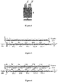
Figure 5 is a schematic diagram showing coating and positions of lugs of a lithium-ion battery cell according to the present disclosure; -
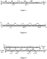
Figure 6 is a diagram showing plate coating and lug distribution of a lithium-ion battery cell according to the present disclosure; -
Figure 7 is a diagram showing arrangement of a plate with an interval of 0.5cm between two positive lugs of a lithium-ion battery cell according to the present disclosure; -
Figure 8 is a diagram showing arrangement of a negative plate with three lugs of a lithium-ion battery cell according to the present disclosure; and -
Figure 9 is a diagram showing arrangement positions of lugs with an laminated structure and a staggered structure of the lithium-ion battery cell according to the present disclosure. - The present disclosure is described more fully hereinafter with reference to the drawings, in which exemplary embodiments of the present disclosure are described. The technical solutions in the embodiments of the present disclosure are described clearly and completely in conjunction with the accompanying drawings in the embodiments of the present disclosure hereinafter. It is apparent that the below-described embodiments are merely some rather than all of embodiments of the present disclosure. All other embodiments obtained by those skilled in the art based on the embodiments in the present disclosure without any creative work should fall within the protection scope of the present disclosure. The technical solutions of the present disclosure are described in various aspects with reference to the drawings and the embodiments.
- Hereinafter, for convenience of description, the terms "left", "right", "upper" and "lower" in the following description are consistent with the left, right, upper, and lower directions of the drawings themselves. The terms "front end", "back end" or "tail end" and the like means the left and right side of the figure itself. In the present disclosure, the words "first", "second" and the like are only used to distinguish in description and have no other special meanings.
- As shown in
Figure 1A to Figure 4 , a lithium-ion battery cell is provided according to the present disclosure. Multiple positive lugs are arranged sequentially on a positive plate in an unfolded state. Multiple negative lugs are arranged sequentially on a negative plate in an unfolded state. The positive plate and the negative plate are separated by a membrane and are wound to form the lithium-ion battery cell through a winding manner. The multiple positive lugs may form a lug laminated structure or a lug staggered structure. The multiple negative lugs may form a lug laminated structure or a lug staggered structure. The multiple positive lugs and the multiple negative lugs may be located at one end of the lithium-ion battery cell, and may also be respectively located at two ends of the lithium-ion battery cell. - The lithium-ion battery cell according to the present disclosure is provided with at least one positive lug and at least one negative lug, such that the battery has a good large-current discharge performance, the density of the lugs may be determined according to actual needs. A multiple-lugs wound design is adopted rather than a laminated design, thereby greatly reducing occurrence of burrs at the edge of the plate and reducing the self-discharge rate, thus improving the stability of the battery.
- In an embodiment, as shown in
Figure 1A , the multiple positive lugs are arranged in parallel in a direction along a length of thepositive plate 6. A first lug margin x1 indicates a distance between a firstpositive lug 2 and a head of thepositive plate 6. The head of thepositive plate 6 indicates the left end of thepositive plate 6, and the firstpositive lug 2 is located closet to the head of thepositive plate 6. Generally, the lugs are not arranged at the leftmost or rightmost of the cell, and lug margins are provided to facilitate package of the cell and prevent occurrence of short circuits. The lug margin indicates a distance from the lug to the edge of the cell. - A distance between each of the multiple positive lugs other than the first positive lug and the head of the
positive plate 6 is indicated by d1, where d1=n1w-x1+(0.5πt∑n1-0.5πt). t indicates a sum of thicknesses of the positive plate, the membrane and the negative plate, that is, a minimum thickness of the winding. w indicates a width of the cell, that is, a width of the innermost layer of the cell. n1 indicates that a positive lug is located at the n1-th w on the positive plate along a direction from the head to a tail of thepositive plate 6, where n1≥2. - For example, in a case of calculating d1 of the
positive lug 4, n1 is 4, thepositive lug 4 is located at the fourth w on thepositive plate 6, where d1=4w-x1+(0.5πt∑4-0.5πt) and ∑4=1 +2+3+4=10. Values of other parameters are substituted into the equation, to calculate d1 of thepositive lug 4, and d1 of each of other positive lugs may be calculated by analogy. - As shown in
Figure 1B , the multiple negative lugs are arranged in parallel in a direction along a length of thenegative plate 5. A second lug margin x2 indicates a distance between a firstnegative lug 1 and the head of thenegative plate 5. A distance between each of the multiple negative lugs other than the first negative lug and the head of thenegative plate 5 is indicated by d2, where d2=n2w-x2+(0.5πt∑n2-0.5πt). n2 indicates that a negative lug is located at the n2-th w on thenegative plate 5 along a direction from a head to a tail of thenegative plate 5, where n2≥2. - For example, in a case of calculating d2 of the
negative lug 3, n2 is 4, thenegative lug 3 is located at the fourth w on thenegative plate 5, where d2=4w-x2+(0.5πt∑4-0.5πt) and ∑4=1+2+3+4=10. Values of other parameters are substituted into the equation, to calculate d2 of thenegative lug 3, and d2 of each of other negative lugs may be calculated by analogy. - In an embodiment, as shown in
Figure 2A , the multiple positive lugs are arranged in parallel in a direction along the length of thepositive plate 6, and the first lug margin x1 indicates the distance between the firstpositive lug 2 and the head of thepositive plate 6. The distance between each of the multiple positive lugs other than the first positive lug and the head of thepositive plate 6 is indicated by d1, where d1=n3w+x1+[0.5πt∑(n3+1)-0.5πt]. n3 indicates that a positive lug is located at the (n3+1)-th w on thepositive plate 6 along the direction from the head to the tail of thepositive plate 6. - For example, in a case of calculating d1 of the
positive lug 4, n3 is 4, thepositive lug 4 is located at the fifth w on the positive plate, where d1=4w+x1+[0.5πt∑(4+1)-0.5πt] and ∑4=1+2+3+4=10. Values of other parameters are substituted into the equation, to calculate d1 of thepositive lug 4, and d1 of each of other positive lugs may be calculated by analogy. - As shown in
Figure 2B , the multiple negative lugs are arranged in parallel in a direction along a length of thenegative plate 5. A second lug margin x2 indicates a distance between the firstnegative lug 1 and the head of thenegative plate 5. A distance between each of the multiple negative lugs other than the first negative lug and the head of thenegative plate 5 is indicated by d2, where d2=n4w+x2+[0.5πt∑(n4+1)-0.5πt]. n4 indicates that a negative lug is located at the (n4+1)-th w on thenegative plate 5 along the direction from the head to the tail of thenegative plate 5. - For example, in a case of calculating d2 of the
negative lug 3, n4 is 4, thenegative lug 3 is located at the fifth w on thenegative plate 5, where d2=4w+x1+[0.5πt∑(4+1)-0.5πt] and ∑4=1+2+3+4=10. Values of other specific parameters are substituted into the equation, to calculate d2 of thenegative lug 3, and d2 of each of other negative lugs may be calculated by analogy. - The lithium-ion battery cell is square, and a membrane is arranged between the
positive plate 6 and thenegative plate 5, two or more layers of the membranes may be arranged. After the lithium-ion battery cell 7 is formed by winding with a winding pin, the multiple positive lugs may form a lug laminated structure and the multiple negative lugs may form a lug laminated structure. As shown inFigure 3 , after the winding, the positive lugs are neatly laminated at one end of thecell 7, and the negative lugs are neatly laminated at the same end of thecell 7 as the positive lugs, where x indicates the lug margin. - The first lug margin x1 and the second lug margin x2 may be the same or different. The first lug margin x1 is less than or equal to 0.5w, and the second lug margin x2 is less than or equal to 0.5w. w indicates a width of the cell, and the width w of the cell is greater than or equal to 5cm and less than or equal to 20cm. h indicates a height, a range of h is 5cm≤h≤20cm. A cell thickness is indicated by d, and a range of d is 0.5cm≤d≤5cm. A length L1 of the negative plate and a length L2 of the
positive plate meet 10w≤L1,L2≤200w. y indicates a length of the tail, where 0≤y<8w. - The lithium-ion battery cell in the above embodiment adopts a winding manner. After the first lug is arranged, positions of the second lug and subsequent lugs may be calculated through the equation nw-x+(0.5πt∑n-0.5πt) or nw+x+[0.5πt∑(n+1)-0.5πt].
- The above two equations are used to calculate the positions of the second and subsequent positive and negative lugs. During calculating a specific position, x is replaced by x1 or x2, and n is replaced by n1, n2, n3 or n4. A position of a lug calculated through nw+x+[0.5πt∑(n+1)-0.5πt is behind the n-th w, and a position of a lug calculated through nw-x+(0.5πt∑n-0.5πt) is in front of the (n+1)-th w.
- In an embodiment, a current collector of the positive plate is aluminum foil, and a current collector of the negative plate is copper foil. The aluminum foil is continuously and uniformly coated with positive electrode slurry containing a lithium-ion active material to form the positive plate, and the copper foil is continuously and uniformly coated with negative electrode slurry containing a lithium-ion active material to form the negative plate. Uncoated regions are reserved on the coated sides of the positive and negative plates for arranging the positive and negative lugs respectively. After the winding, two or more lugs are welded together by using ultrasonic, or the lugs are directly welded to a transition metal plate, and the transition metal plate is welded to a top cover of the battery case subsequently.
- The cell is formed with a winding manner by welding multiple lugs, such that the rate performance of a large and medium-sized lithium-ion battery is improved, and good consistency and stability of the battery can be obtained, thereby facilitating grouping and modularized expansion, thus ensuring a stable operation of the system and prolonging a service life of the system.
- After the positions of the lugs are calculated through the above equations, the lugs are moved forward or backward by a certain distance to form a lug staggered structure. d1 of each of the m1 positive lugs in the multiple positive lugs is increased or decreased by a first interval value corresponding the positive lug, such that the multiple positive lugs form a lug staggered structure. That is, there are m1 positive lugs being staggered in the multiple laminated positive lugs, where m1 may be 1, 2, 3 and the like. Intervals between adjacent staggered positive lugs may be the same or different.
- The multiple negative lugs may form a lug staggered structure. d2 of each of the m2 negative lugs in the multiple negative lugs is increased or decreased by a second interval value corresponding the negative lug, such that there are m2 negative lugs being staggered in the multiple laminated negative lugs, where m2 may be 1, 2, 3 and the like. Intervals between adjacent staggered negative lugs may be the same or different. For example, the arrangement 1' of the negative electrode and the arrangement 2' of the positive electrode in
Figure 4 are in a staggered manner. - In an embodiment, the intervals between adjacent staggered positive lugs in the m1 positive lugs are the same. Starting from the first one in the m1 positive lugs, d1 of each of the m1 positive lugs is decreased by a first interval value mq. Where d1=n1w-x1+(0.5πt∑n1-0.5πt), q indicates an interval between two adjacent staggered positive lugs, and m indicates a sequence number of a positive lug in the m1 positive lugs along a direction from the head to the tail of the positive plate, where 1≤m≤m1.
- Alternatively, starting from the first one in the m1 positive lugs, d1 of each of the m1 positive lugs is increased by a first interval value mq. Where d1=n3w+x1+[0.5πt∑(n3+1)-0.5πt], q indicates an interval between two adjacent staggered positive lugs, m indicates a sequence number of a positive lug in the m1 positive lugs along a direction from the head to the tail of the positive plate, where 1≤m≤m1.
- The intervals between adjacent staggered negative lugs in the m2 negative lugs are the same. Starting from the first one in the m2 negative lugs, d2 of each of the m2 negative lugs is decreased by a first interval value mq. Where d2=n2w-x2+(0.5πt∑n2-0.5πt), q indicates an interval between two adjacent staggered negative lugs, m indicates a sequence number of a negative lug in the m2 negative lugs along a direction from the head to the tail of the negative plate, where 1≤m≤m2.
- Alternatively, starting from the first one in the m2 negative lugs, d2 of each of the m2 negative lugs is increased by a first interval value mq. Where d2=n4w+x2+[0.5πt∑(n4+1)-0.5πt], q indicates an interval between two adjacent staggered negative lugs, m indicates a sequence number of a negative lug in the m2 negative lugs along a direction from the head to the tail of the negative plate, where 1≤m≤m2.
- A case where the lugs of the lithium-ion battery cell are laminated meets the following equations nw+x+[0.5πt∑(n+1)-0.5πt and nw-x+(0.5πt∑n-0.5πt). Based on the above two equations, the lugs are moved forward or backward by a certain distance. Starting from the first one in the lugs with incremented sequence numbers, a position of the lug is moved inward or outward by mq, where m=1, 2, 3,.... For the first lug, m=1, for the second lug, m=2, and for other cases, m may be determined by analogy, where q indicates an interval between two lugs (0<q <5cm).
- The lugs are staggered and an interval between two adjacent lugs is indicated by q. If the first lug is in the middle, a lug on the left is moved outward by q, and a lug on the right is moved inward by q. For the lugs whose positions are calculated through nw-x+(0.5πt∑n-0.5πt), since the lugs are located behind the nw, it is required to moved forward the lugs starting from the second lug. For the lugs whose positions are calculated through nw+x+[0.5πt∑(n+1)-0.5πt], since the lugs are located in front of the (n+1)w, it is required to move backward the lugs starting from the second lug.
- A lithium-ion battery is further provided according to the present disclosure, which includes a battery case and the lithium-ion battery cell as described above located in the battery case. The negative lugs and the positive lugs are located on the same side of the battery cell, the positive and negative lugs may be connected to an electrode pillar of the battery case by a bolt or through a riveting process. The battery case is made of aluminum.
- The positive plate is coated with positive electrode slurry, the positive electrode slurry is made by mixing a positive electrode powder, a conductive agent, an adhesive and an additive. The negative plate is coated with negative electrode slurry, the negative electrode slurry is made by mixing a negative electrode powder, a conductive agent, an adhesive and an additive. In order to avoid occurrence of lithium precipitation at a negative electrode due to a positive electrode corresponding to a negative lug, in addition to coating a glue to protect the negative lug, the performance of the slurry is improved to avoid the occurrence of lithium precipitation.
- In an embodiment, both thicknesses of a side wall and a front wall of the aluminum case are 0.3mm. A thickness of a bottom is 0.6mm. A thickness d of the cell is designed to be 0.82cm. A width of the positive plate is 14cm. A width of the negative plate is 14.2cm. A width of the membrane is 14.5cm .
- The positive active material is a ternary material and has a specific capacity of 150mAh/g. The negative active material is artificial graphite or composite graphite, and has a specific capacity of 345mAh/g, and a capacity of the negative electrode is excessive by 4%. The composition of the positive electrode slurry is: 95.5% of the ternary material, 2% of the adhesive, 1.5% of the conductive agent and 1% of a nano inorganic functional additive. The compacted density is 3.6g/cm3, a thickness of a single-layer coating is 0.064mm, the surface density is 461g/m2, a thickness of the current collector aluminum foil is 0.012mm, and the calculated unit capacity is 7.224mAh/cm2.
- The composition of the negative electrode slurry is: 95.5% of the ternary material, 1.2% of a thickener, 1.5% of the adhesive, 1% of the conductive agent and 0.8% of a nano inorganic functional additive. The compacted density is 1.5g/cm3, a thickness of a single-layer coating is 0.070mm, a surface density is 224g/m2, a thickness of the current collector aluminum foil is 0.009mm, and the calculated unit capacity is 7.4mAh/cm2. t is 0.33mm.
- Based on the thicknesses of the cell, the positive and negative plates and the membrane, a length of a plate with a coating is 175cm, specific coating sizes are shown in the following table 1, and the capacity of the battery is 35Ah. The schematic diagram of coating is as shown in
Figure 5 , where x is set to 1.5cm, a width of the lug is 1.5cm, and w is calculated as 7cm (a width of the innermost unit roll layer after the winding pin is pulled out).Table 1 list of coating sizes of the positive and negative plates A B C D Total length of the plate Negative plate 8 11.5 3 3 188 Positive plate 4.7 14.8 28 14.4 205.9 - In order to design a lug laminated structure, the positive and negative plates are respectively provided with six lugs. Positions of the lugs may be calculated through the following equation nw+x+[0.5πt∑(n+1)-0.5πt]. The calculated positions of the lugs are as shown in
Figure 5 (the interval between the positive lugs is the same as the interval between the negative lugs). The lugs may be directly welded to the aluminum cover, or may be first welded to a large transition metal plate, and the transition metal plate is welded to the aluminum cover. - In order to avoid occurrence of lithium precipitation of a negative lug, in addition to coating a glue to protect the negative lug, the performance of the slurry is improved to avoid the occurrence of lithium precipitation. A highly wet negative active material such as a lightly oxidized graphite material may be used. A silicon carbon negative electrode material may be used, which has a certain absorption effect on increase of the capacity.
- In an embodiment, the positions of the positive lugs are the same as the positions of the positive lugs in
Figure 5 , and the positions of the negative lugs are set according to the following equation nw-x+(0.5πt∑n-0.5πt), which are as shown inFigure 6 . - In an embodiment, the lugs of the lithium-ion battery cell are staggered, each of the positive plate and negative plate is provided with two lugs, where an interval between the lugs is 0.5cm. for a case where the lugs are distributed based on the following equation nw-x+(0.5πt∑n-0.5πt), a staggered arrangement is formed by moving one of the lugs forward by 0.5cm, where intervals between the staggered lugs are the same.
- For a case where the lugs are distributed based on the following equation nw+x+[0.5πt∑(n+1)-0.5πt], a staggered arrangement is formed by moving one of the lugs backward by 0.5cm. For example, for a positive lug with a position calculated through nw+x+[0.5πt∑(n+1)-0.5πt], if n=8, the lug is at a position of 60.3cm; if n=16, the lug is at a position of 121.9cm, the positions of the lugs are as shown in
Figure 7 . - In an embodiment, the lugs of the lithium-ion battery cell are staggered. Each of the positive plate and negative plate is provided with three lugs, where each lug has a width of 1cm, and intervals of the staggered lugs are 0.4cm. For the negative plate in which a position of a lug is calculated through the following equation nw-x+(0.5πt∑n-0.5πt), the first lug is at a position of n=6. The next lug is at a position moved forward by 0.4cm from a position of n=14. The third lug is at a position moved forward by 0.8cm from a position of n=22. The positions of the negative lugs are as shown in
Figure 8 . The positions of the positive lugs are similar to that of the negative lugs. - In an embodiment, the lugs of the lithium-ion battery cell have a lug laminated structure or a lug staggered structure. Two groups of lugs are laminated, and intervals between the staggered lugs are 0.5cm. The laminated lugs are located at positions calculated through the following equation nw+x+[0.5πt∑(n+1)-0.5πt], and the staggered lugs are located at positions calculated through the following equation nw+x+[0.5πt∑(n+1)-0.5πt∑]+0.5. As shown in
Figure 9 , n for the laminated lugs are 4 and 8 (corresponding to positions of 30.2cm and 59.8cm), and n for another group of the laminated lugs are 16 and 20 (corresponding to positions of 121.9cm and 153.9cm). In other words, the laminated lugs are located at positions calculated through the following equation nw-x+(0.5πt∑n-0.5πt), and the staggered lugs are located at positions calculated through the following equation nw-x+(0.5πt∑n-0.5πt)-0.5. - In the above embodiments, the lithium-ion battery cell and the lithium-ion battery adopt a multi-lug design, which greatly improves the rate performance of the battery. With the multi-lug design based on the winding manner, the consistency of the cell is improved, thereby facilitating grouping and modularized expansion, thus ensuring the stable operation of the system and prolonging the service life of the system. In order to avoid the complicated process of blanking a region on the positive region corresponding to the negative lug, a simple method of improving the composition of the slurry is adopted, thereby avoiding the occurrence of lithium precipitation at the negative electrode, thus improving the production efficiency while improving the safety performance. The winding multi-lug design is adopted instead of the laminated design, thereby greatly reducing the occurrence of burrs at the edge of the plate and reducing the self-discharging rate, thus improving the stability of the battery.
- The method and the system of the present disclosure may be implemented in many ways. For example, the method and the system of the present disclosure may be implemented by software, hardware, firmware or any combination of the software, the hardware and the firmware. The above sequence of steps used in the method is only for illustration, and the steps of the method of the present disclosure are not limited to the above-described specific order unless otherwise specified. In addition, in some embodiments, the present disclosure may also be implemented as programs recorded in a recording medium, the programs include machine-readable instructions for implementing the method according to the present disclosure. Thus, the present disclosure also covers a recording medium storing a program for executing the method according to the present disclosure.
- The description of the present disclosure is presented for illustration and description, but is not intended to be exhaustive or limit the disclosure to the forms disclosed. Many modifications and variations are apparent to those skilled in the art. The embodiments were chosen and described to best explain the principles and the practical applications of the disclosure, and to enable those skilled in the art to understand the disclosure to design various embodiments with various modifications that are applicable to particular uses.
Claims (18)
- A lithium-ion battery cell, comprising:a positive plate;a membrane; anda negative plate, whereina plurality of positive lugs is arranged sequentially on the positive plate in a unfolded state, a plurality of negative lugs is arranged sequentially on the negative plate in a unfolded state, andthe positive plate and the negative plate are separated by the membrane and are wound to form the lithium-ion battery cell, the plurality of positive lugs forms a lug laminated structure or a lug staggered structure, and the plurality of negative lugs forms a lug laminated structure or a lug staggered structure.
- The lithium-ion battery cell according to claim 1, wherein
the plurality of positive lugs is arranged in parallel in a direction along a length of the positive plate;
a first lug margin x1 indicates a distance between a first positive lug and a head of the positive plate, a distance between each of the positive lugs other than the first positive lug and the head of the positive plate is indicated by d1, with d1=n1w-x1+(0.5πt∑n1-0.5πt) or d1=n3w+x1+[0.5πt∑(n3+1)-0.5πt];
the lithium-ion battery cell is square, and the plurality of positive lugs forms the lug laminated structure;
where t indicates a sum of thicknesses of the positive plate, the membrane and the negative plate, w indicates a width of the cell, the first positive lug is the one of the positive lugs which is located closest to the head of the positive plate, n1 indicates that a positive lug is located at the n1-th w on the positive plate along a direction from the head to a tail of the positive plate, and n3 indicates that a positive lug is located at the (n3+1)-th w on the positive plate along the direction from the head to the tail of the positive plate. - The lithium-ion battery cell according to claim 2, wherein
the plurality of negative lugs is arranged in parallel in a direction along a length of the negative plate;
a second lug margin x2 indicates a distance between a first negative lug and a head of the negative plate, a distance between each of the negative lugs other than the first negative lug and the head of the negative plate is indicated by d2, with d2=n2w-x2+(0.5πt∑n2-0.5πt) or d2=n4w+x2+[0.5πt∑(n4+1)-0.5πt];
the plurality of negative lugs forms the lug laminated structure;
the first negative lug is the one of the negative lugs which is located closest to the head of the negative plate;
where n2 indicates that a negative lug is located at the n2-th w on the negative plate along a direction from the head to a tail of the negative plate, and n4 indicates that a negative lug is located at the (n4+1)-th w on the negative plate along the direction from the head to the tail of the negative plate. - The lithium-ion battery cell according to claim 3, wherein
the plurality of positive lugs forms the lug staggered structure, wherein d1 of each of m1 positive lugs in the plurality of positive lugs is increased or decreased by a first interval value corresponding to the positive lug; and/or
the plurality of negative lugs forms the lug staggered structure, wherein d2 of each of m2 negative lugs in the plurality of negative lugs is increased or decreased by a second interval value corresponding to the negative lug. - The lithium-ion battery cell according to claim 4, wherein intervals between adjacent staggered positive lugs in the m1 positive lugs are the same.
- The lithium-ion battery cell according to claim 5, wherein
starting from the first one in the m1 positive lugs, d1 of each of the m1 positive lugs is decreased by a first interval value mq;
wherein d1=n1w-x1+(0.5πt∑n1-0.5πt), q indicates an interval between two adjacent staggered positive lugs, m indicates a sequence number of a positive lug in the m1 positive lugs along a direction from the head to the tail of the positive plate, 1≤m≤m1. - The lithium-ion battery cell according to claim 5, wherein
starting from the first one in the m1 positive lugs, d1 of each of the m1 positive lugs is increased by a first interval value mq;
wherein d1=n3w+x1+[0.5πt∑(n3+1)-0.5πt], q indicates an interval between two adjacent staggered positive lugs, m indicates a sequence number of a positive lug in the m1 positive lugs along a direction from the head to tail of the positive plate 1≤m≤m1. - The lithium-ion battery cell according to claim 4, wherein intervals between adjacent staggered negative lugs in the m2 negative lugs are the same.
- The lithium-ion battery cell according to claim 8, wherein
starting from the first one in the m2 negative lugs, d2 of each of the m2 negative lugs is decreased by a first interval value mq;
wherein d2=n2w-x2+(0.5πt∑n2-0.5πt), q indicates an interval between two adjacent staggered negative lugs, m indicates a sequence number of a negative lug in the m2 negative lugs along a direction from the head to the tail of the negative plate, 1≤m≤m2. - The lithium-ion battery cell according to claim 8, wherein
starting from the first one in the m2 negative lugs, d2 of each of the m2 negative lugs is increased by a the first interval value mq;
wherein d2=n4w+x2+[0.5πt∑(n4+1)-0.5πt], q indicates an interval between two adjacent staggered negative lugs, m indicates a sequence number of a negative lug in the m2 negative lugs along a direction from the head to the tail of the negative plate, 1≤m≤m2. - The lithium-ion battery cell according to claim 3, wherein
the first lug margin x1 is less than or equal to 0.5w; and
the second lug margin x2 is less than or equal to 0.5w. - The lithium-ion battery cell according to claim 3, wherein the width w of the cell is greater than or equal to 5cm and is less than or equal to 20cm.
- The lithium-ion battery cell according to claim 3, wherein
a distance between the tail of the positive plate and a positive lug closest to the tail of the positive plate is less than 8w; and
a distance between the tail of the negative plate and a negative lug closest to the tail of the negative plate is less than 8w. - The lithium-ion battery cell according to claim 1, wherein
the positive lug is made of aluminum or aluminum-nickel alloy; and
the negative lug is made of nickel, copper or copper-nickel alloy. - The lithium-ion battery cell according to claim 1, wherein
the plurality of positive lugs is welded together by using ultrasonic; and
the plurality of negative lugs is welded together by using ultrasonic. - The lithium-ion battery cell according to claim 1, wherein
the positive plate is coated with positive electrode slurry which is made by mixing a positive electrode powder, a conductive agent, an adhesive and an additive; and
the negative plate is coated with negative electrode slurry which is made by mixing a negative electrode powder, a conductive agent, an adhesive and an additive. - A lithium-ion battery, comprising a battery case and the lithium-ion battery cell, according to any one of claims 1 to 16, in the battery case.
- The lithium-ion battery according to claim 17, wherein the battery case is made of aluminum.
Applications Claiming Priority (2)
| Application Number | Priority Date | Filing Date | Title |
|---|---|---|---|
| CN201510861234.XA CN105355983B (en) | 2015-11-30 | 2015-11-30 | Lithium ion battery cell and lithium ion battery |
| PCT/CN2016/103256 WO2017092520A1 (en) | 2015-11-30 | 2016-10-25 | Lithium-ion battery cell and lithium-ion battery |
Publications (3)
| Publication Number | Publication Date |
|---|---|
| EP3386025A1 true EP3386025A1 (en) | 2018-10-10 |
| EP3386025A4 EP3386025A4 (en) | 2019-07-10 |
| EP3386025B1 EP3386025B1 (en) | 2021-07-21 |
Family
ID=55331900
Family Applications (1)
| Application Number | Title | Priority Date | Filing Date |
|---|---|---|---|
| EP16869830.6A Active EP3386025B1 (en) | 2015-11-30 | 2016-10-25 | Lithium-ion battery cell and lithium-ion battery |
Country Status (7)
| Country | Link |
|---|---|
| US (1) | US20180342759A1 (en) |
| EP (1) | EP3386025B1 (en) |
| CN (1) | CN105355983B (en) |
| AU (1) | AU2016364095B2 (en) |
| CA (1) | CA3004955C (en) |
| ES (1) | ES2895046T3 (en) |
| WO (1) | WO2017092520A1 (en) |
Families Citing this family (12)
| Publication number | Priority date | Publication date | Assignee | Title |
|---|---|---|---|---|
| CN105355983B (en) * | 2015-11-30 | 2018-05-11 | 珠海格力电器股份有限公司 | Lithium ion battery cell and lithium ion battery |
| CN108987655A (en) * | 2017-05-31 | 2018-12-11 | 东莞新能源科技有限公司 | Battery with a battery cell |
| CN108461829B (en) * | 2018-07-20 | 2018-11-02 | 上海瑞浦青创新能源有限公司 | A kind of battery core of coiled lithium ion battery |
| CN108461811B (en) * | 2018-07-20 | 2019-11-05 | 瑞浦能源有限公司 | Pole piece and battery cell for coiled lithium ion battery |
| CN109802088B (en) * | 2019-03-20 | 2020-10-09 | 江西理工大学 | Lithium ion battery capable of being quickly charged and manufacturing method thereof |
| CN115275365B (en) | 2019-09-25 | 2025-08-19 | 荣耀终端股份有限公司 | Battery module supporting high-power quick charge, charging module and electronic equipment |
| CN112889181B (en) | 2020-01-20 | 2022-06-17 | 宁德新能源科技有限公司 | Electrode assembly and battery |
| CN112736219A (en) * | 2021-01-12 | 2021-04-30 | 苏州领湃新能源科技有限公司 | Method for preparing vehicle lithium battery, vehicle lithium battery and automobile |
| CN113517472B (en) * | 2021-03-18 | 2022-12-23 | 河南鑫泉能源科技有限公司 | Alignment method for positive and double-pole ears of cylindrical lithium ion battery |
| CN115566373B (en) * | 2022-12-07 | 2023-03-03 | 楚能新能源股份有限公司 | A misplaced full tab pole piece, wound battery cell and cylindrical battery |
| CN116093555B (en) * | 2023-03-13 | 2025-08-01 | 江苏中兴派能电池有限公司 | Cell structure and battery |
| CN116544624A (en) * | 2023-06-05 | 2023-08-04 | 天津聚元新能源科技有限公司 | Multipolar ear cell structure and preparation method thereof |
Family Cites Families (14)
| Publication number | Priority date | Publication date | Assignee | Title |
|---|---|---|---|---|
| CN1921180A (en) * | 2005-08-26 | 2007-02-28 | 周基平 | Lithium ion battery pole piece, electricity core and method for making same |
| US7433174B2 (en) * | 2006-07-06 | 2008-10-07 | Maxwell Technologies, Inc. | Method of making, apparatus, and article of manufacturing for an electrode termination contact interface |
| CN101106203A (en) * | 2007-08-08 | 2008-01-16 | 北京中润恒动电池有限公司 | Lithium battery with new electrode structure and its making method |
| US8399116B2 (en) * | 2007-12-25 | 2013-03-19 | Byd Co. Ltd. | Optimized dimensional relationships for an electrochemical cell having a coiled core |
| KR101137372B1 (en) * | 2009-09-18 | 2012-04-20 | 삼성에스디아이 주식회사 | Method of manufacturing electrode assembly for rechargeable battery |
| CN101950816A (en) * | 2010-09-21 | 2011-01-19 | 奇瑞汽车股份有限公司 | Square power lithium ion battery cell and manufacturing method thereof |
| CN102437377A (en) * | 2011-12-12 | 2012-05-02 | 深圳市格瑞普电池有限公司 | Winding electric core body, soft package lithium ion battery and pole piece |
| CN102544437A (en) * | 2012-02-16 | 2012-07-04 | 浙江兴海能源科技有限公司 | Differential pitch pole piece and power battery adopting same |
| KR20150030537A (en) * | 2013-09-12 | 2015-03-20 | 디지야 에너지 세이빙 테크놀로지 인코포레이티드 | Single winding core having plural tabs, lithium cell with the single winding core and successive winding method for the single winding core |
| CN203787498U (en) * | 2014-04-18 | 2014-08-20 | 宁德时代新能源科技有限公司 | Electrode lug connecting structure of battery pack |
| KR102368090B1 (en) * | 2015-01-28 | 2022-02-24 | 삼성에스디아이 주식회사 | Electrode assembly and rechargeable battery having electrode ta1p |
| CN105070880B (en) * | 2015-07-29 | 2017-08-25 | 佛山市实达科技有限公司 | Lithium ion battery with auxiliary lug pole piece and with auxiliary lug pole piece |
| CN205141088U (en) * | 2015-11-30 | 2016-04-06 | 珠海格力电器股份有限公司 | Lithium ion battery cell and lithium ion battery |
| CN105355983B (en) * | 2015-11-30 | 2018-05-11 | 珠海格力电器股份有限公司 | Lithium ion battery cell and lithium ion battery |
-
2015
- 2015-11-30 CN CN201510861234.XA patent/CN105355983B/en active Active
-
2016
- 2016-10-25 CA CA3004955A patent/CA3004955C/en active Active
- 2016-10-25 ES ES16869830T patent/ES2895046T3/en active Active
- 2016-10-25 EP EP16869830.6A patent/EP3386025B1/en active Active
- 2016-10-25 WO PCT/CN2016/103256 patent/WO2017092520A1/en not_active Ceased
- 2016-10-25 AU AU2016364095A patent/AU2016364095B2/en active Active
- 2016-10-25 US US15/779,384 patent/US20180342759A1/en not_active Abandoned
Also Published As
| Publication number | Publication date |
|---|---|
| CN105355983A (en) | 2016-02-24 |
| US20180342759A1 (en) | 2018-11-29 |
| CA3004955A1 (en) | 2017-06-08 |
| WO2017092520A1 (en) | 2017-06-08 |
| EP3386025A4 (en) | 2019-07-10 |
| AU2016364095A1 (en) | 2018-06-07 |
| ES2895046T3 (en) | 2022-02-17 |
| CN105355983B (en) | 2018-05-11 |
| CA3004955C (en) | 2020-12-29 |
| AU2016364095B2 (en) | 2020-02-06 |
| EP3386025B1 (en) | 2021-07-21 |
Similar Documents
| Publication | Publication Date | Title |
|---|---|---|
| AU2016364095B2 (en) | Lithium-ion battery cell and lithium-ion battery | |
| JP6136027B2 (en) | Electrode assembly, battery cell and device including the same | |
| KR102858551B1 (en) | Composite current collectors, electrodes, secondary batteries, battery modules, battery packs and electrical devices | |
| EP4513582A1 (en) | Electrochemical apparatus and electrical device | |
| CN217158236U (en) | Electrode Pieces, Electrode Assemblies and Batteries | |
| CN101106203A (en) | Lithium battery with new electrode structure and its making method | |
| CN105355962A (en) | A kind of preparation method of wound laminated battery | |
| CN104681878A (en) | Manufacturing method of winding type lithium ion battery and winding type lithium ion battery | |
| CN205543110U (en) | Square power battery | |
| CN110931840A (en) | Multi-winding-core unit stacking type battery cell | |
| CN205141088U (en) | Lithium ion battery cell and lithium ion battery | |
| CN120109270A (en) | All-solid-state battery cell and method for manufacturing the same | |
| CN218602513U (en) | Battery cell and battery | |
| CN114284548A (en) | Battery cell of all-solid-state battery, all-solid-state battery and electronic equipment | |
| CN223006810U (en) | Safety lithium battery | |
| CN223066284U (en) | A battery casing with self-constraint | |
| CN221551951U (en) | Battery structure for improving consistency of temperature rise of battery cells | |
| JP7782122B2 (en) | Electrode assembly and battery cell including the same | |
| CN218975473U (en) | Pole pieces, batteries, vehicles and battery manufacturing equipment | |
| CN203386863U (en) | Lithium ion battery and lithium ion battery pack | |
| CN224153411U (en) | A stacked battery and an electrical device | |
| CN221262655U (en) | Pole piece, battery core and battery | |
| CN220710345U (en) | Pole pieces, electrode components, battery cells, batteries and electrical devices | |
| CN222422022U (en) | Battery assembly and vehicle | |
| EP4618208A1 (en) | Secondary battery, battery module including the secondary battery, battery pack including the battery module, and vehicle including the battery pack |
Legal Events
| Date | Code | Title | Description |
|---|---|---|---|
| STAA | Information on the status of an ep patent application or granted ep patent |
Free format text: STATUS: THE INTERNATIONAL PUBLICATION HAS BEEN MADE |
|
| PUAI | Public reference made under article 153(3) epc to a published international application that has entered the european phase |
Free format text: ORIGINAL CODE: 0009012 |
|
| STAA | Information on the status of an ep patent application or granted ep patent |
Free format text: STATUS: REQUEST FOR EXAMINATION WAS MADE |
|
| 17P | Request for examination filed |
Effective date: 20180524 |
|
| AK | Designated contracting states |
Kind code of ref document: A1 Designated state(s): AL AT BE BG CH CY CZ DE DK EE ES FI FR GB GR HR HU IE IS IT LI LT LU LV MC MK MT NL NO PL PT RO RS SE SI SK SM TR |
|
| AX | Request for extension of the european patent |
Extension state: BA ME |
|
| DAV | Request for validation of the european patent (deleted) | ||
| DAX | Request for extension of the european patent (deleted) | ||
| A4 | Supplementary search report drawn up and despatched |
Effective date: 20190611 |
|
| RIC1 | Information provided on ipc code assigned before grant |
Ipc: H01M 10/0587 20100101AFI20190604BHEP Ipc: H01M 10/0525 20100101ALI20190604BHEP Ipc: H01M 4/02 20060101ALI20190604BHEP Ipc: H01M 10/04 20060101ALI20190604BHEP Ipc: H01M 2/30 20060101ALI20190604BHEP Ipc: H01M 2/26 20060101ALI20190604BHEP |
|
| STAA | Information on the status of an ep patent application or granted ep patent |
Free format text: STATUS: EXAMINATION IS IN PROGRESS |
|
| 17Q | First examination report despatched |
Effective date: 20200129 |
|
| GRAP | Despatch of communication of intention to grant a patent |
Free format text: ORIGINAL CODE: EPIDOSNIGR1 |
|
| STAA | Information on the status of an ep patent application or granted ep patent |
Free format text: STATUS: GRANT OF PATENT IS INTENDED |
|
| RIC1 | Information provided on ipc code assigned before grant |
Ipc: H01M 10/04 20060101ALI20210120BHEP Ipc: H01M 4/02 20060101ALI20210120BHEP Ipc: H01M 50/538 20210101ALI20210120BHEP Ipc: H01M 10/0587 20100101AFI20210120BHEP Ipc: H01M 10/0525 20100101ALI20210120BHEP |
|
| INTG | Intention to grant announced |
Effective date: 20210211 |
|
| GRAS | Grant fee paid |
Free format text: ORIGINAL CODE: EPIDOSNIGR3 |
|
| GRAA | (expected) grant |
Free format text: ORIGINAL CODE: 0009210 |
|
| STAA | Information on the status of an ep patent application or granted ep patent |
Free format text: STATUS: THE PATENT HAS BEEN GRANTED |
|
| AK | Designated contracting states |
Kind code of ref document: B1 Designated state(s): AL AT BE BG CH CY CZ DE DK EE ES FI FR GB GR HR HU IE IS IT LI LT LU LV MC MK MT NL NO PL PT RO RS SE SI SK SM TR |
|
| REG | Reference to a national code |
Ref country code: GB Ref legal event code: FG4D |
|
| REG | Reference to a national code |
Ref country code: CH Ref legal event code: EP |
|
| REG | Reference to a national code |
Ref country code: DE Ref legal event code: R096 Ref document number: 602016061091 Country of ref document: DE |
|
| REG | Reference to a national code |
Ref country code: AT Ref legal event code: REF Ref document number: 1413437 Country of ref document: AT Kind code of ref document: T Effective date: 20210815 |
|
| REG | Reference to a national code |
Ref country code: IE Ref legal event code: FG4D |
|
| REG | Reference to a national code |
Ref country code: NL Ref legal event code: FP |
|
| REG | Reference to a national code |
Ref country code: LT Ref legal event code: MG9D |
|
| REG | Reference to a national code |
Ref country code: AT Ref legal event code: MK05 Ref document number: 1413437 Country of ref document: AT Kind code of ref document: T Effective date: 20210721 |
|
| PG25 | Lapsed in a contracting state [announced via postgrant information from national office to epo] |
Ref country code: RS Free format text: LAPSE BECAUSE OF FAILURE TO SUBMIT A TRANSLATION OF THE DESCRIPTION OR TO PAY THE FEE WITHIN THE PRESCRIBED TIME-LIMIT Effective date: 20210721 Ref country code: SE Free format text: LAPSE BECAUSE OF FAILURE TO SUBMIT A TRANSLATION OF THE DESCRIPTION OR TO PAY THE FEE WITHIN THE PRESCRIBED TIME-LIMIT Effective date: 20210721 Ref country code: LT Free format text: LAPSE BECAUSE OF FAILURE TO SUBMIT A TRANSLATION OF THE DESCRIPTION OR TO PAY THE FEE WITHIN THE PRESCRIBED TIME-LIMIT Effective date: 20210721 Ref country code: BG Free format text: LAPSE BECAUSE OF FAILURE TO SUBMIT A TRANSLATION OF THE DESCRIPTION OR TO PAY THE FEE WITHIN THE PRESCRIBED TIME-LIMIT Effective date: 20211021 Ref country code: AT Free format text: LAPSE BECAUSE OF FAILURE TO SUBMIT A TRANSLATION OF THE DESCRIPTION OR TO PAY THE FEE WITHIN THE PRESCRIBED TIME-LIMIT Effective date: 20210721 Ref country code: HR Free format text: LAPSE BECAUSE OF FAILURE TO SUBMIT A TRANSLATION OF THE DESCRIPTION OR TO PAY THE FEE WITHIN THE PRESCRIBED TIME-LIMIT Effective date: 20210721 Ref country code: FI Free format text: LAPSE BECAUSE OF FAILURE TO SUBMIT A TRANSLATION OF THE DESCRIPTION OR TO PAY THE FEE WITHIN THE PRESCRIBED TIME-LIMIT Effective date: 20210721 Ref country code: PT Free format text: LAPSE BECAUSE OF FAILURE TO SUBMIT A TRANSLATION OF THE DESCRIPTION OR TO PAY THE FEE WITHIN THE PRESCRIBED TIME-LIMIT Effective date: 20211122 Ref country code: NO Free format text: LAPSE BECAUSE OF FAILURE TO SUBMIT A TRANSLATION OF THE DESCRIPTION OR TO PAY THE FEE WITHIN THE PRESCRIBED TIME-LIMIT Effective date: 20211021 |
|
| REG | Reference to a national code |
Ref country code: ES Ref legal event code: FG2A Ref document number: 2895046 Country of ref document: ES Kind code of ref document: T3 Effective date: 20220217 |
|
| PG25 | Lapsed in a contracting state [announced via postgrant information from national office to epo] |
Ref country code: PL Free format text: LAPSE BECAUSE OF FAILURE TO SUBMIT A TRANSLATION OF THE DESCRIPTION OR TO PAY THE FEE WITHIN THE PRESCRIBED TIME-LIMIT Effective date: 20210721 Ref country code: LV Free format text: LAPSE BECAUSE OF FAILURE TO SUBMIT A TRANSLATION OF THE DESCRIPTION OR TO PAY THE FEE WITHIN THE PRESCRIBED TIME-LIMIT Effective date: 20210721 Ref country code: GR Free format text: LAPSE BECAUSE OF FAILURE TO SUBMIT A TRANSLATION OF THE DESCRIPTION OR TO PAY THE FEE WITHIN THE PRESCRIBED TIME-LIMIT Effective date: 20211022 |
|
| REG | Reference to a national code |
Ref country code: DE Ref legal event code: R097 Ref document number: 602016061091 Country of ref document: DE |
|
| PG25 | Lapsed in a contracting state [announced via postgrant information from national office to epo] |
Ref country code: DK Free format text: LAPSE BECAUSE OF FAILURE TO SUBMIT A TRANSLATION OF THE DESCRIPTION OR TO PAY THE FEE WITHIN THE PRESCRIBED TIME-LIMIT Effective date: 20210721 |
|
| PLBE | No opposition filed within time limit |
Free format text: ORIGINAL CODE: 0009261 |
|
| STAA | Information on the status of an ep patent application or granted ep patent |
Free format text: STATUS: NO OPPOSITION FILED WITHIN TIME LIMIT |
|
| REG | Reference to a national code |
Ref country code: CH Ref legal event code: PL |
|
| PG25 | Lapsed in a contracting state [announced via postgrant information from national office to epo] |
Ref country code: SM Free format text: LAPSE BECAUSE OF FAILURE TO SUBMIT A TRANSLATION OF THE DESCRIPTION OR TO PAY THE FEE WITHIN THE PRESCRIBED TIME-LIMIT Effective date: 20210721 Ref country code: SK Free format text: LAPSE BECAUSE OF FAILURE TO SUBMIT A TRANSLATION OF THE DESCRIPTION OR TO PAY THE FEE WITHIN THE PRESCRIBED TIME-LIMIT Effective date: 20210721 Ref country code: RO Free format text: LAPSE BECAUSE OF FAILURE TO SUBMIT A TRANSLATION OF THE DESCRIPTION OR TO PAY THE FEE WITHIN THE PRESCRIBED TIME-LIMIT Effective date: 20210721 Ref country code: EE Free format text: LAPSE BECAUSE OF FAILURE TO SUBMIT A TRANSLATION OF THE DESCRIPTION OR TO PAY THE FEE WITHIN THE PRESCRIBED TIME-LIMIT Effective date: 20210721 Ref country code: CZ Free format text: LAPSE BECAUSE OF FAILURE TO SUBMIT A TRANSLATION OF THE DESCRIPTION OR TO PAY THE FEE WITHIN THE PRESCRIBED TIME-LIMIT Effective date: 20210721 Ref country code: AL Free format text: LAPSE BECAUSE OF FAILURE TO SUBMIT A TRANSLATION OF THE DESCRIPTION OR TO PAY THE FEE WITHIN THE PRESCRIBED TIME-LIMIT Effective date: 20210721 |
|
| REG | Reference to a national code |
Ref country code: BE Ref legal event code: MM Effective date: 20211031 |
|
| 26N | No opposition filed |
Effective date: 20220422 |
|
| PG25 | Lapsed in a contracting state [announced via postgrant information from national office to epo] |
Ref country code: MC Free format text: LAPSE BECAUSE OF FAILURE TO SUBMIT A TRANSLATION OF THE DESCRIPTION OR TO PAY THE FEE WITHIN THE PRESCRIBED TIME-LIMIT Effective date: 20210721 |
|
| PG25 | Lapsed in a contracting state [announced via postgrant information from national office to epo] |
Ref country code: LU Free format text: LAPSE BECAUSE OF NON-PAYMENT OF DUE FEES Effective date: 20211025 Ref country code: BE Free format text: LAPSE BECAUSE OF NON-PAYMENT OF DUE FEES Effective date: 20211031 |
|
| PG25 | Lapsed in a contracting state [announced via postgrant information from national office to epo] |
Ref country code: LI Free format text: LAPSE BECAUSE OF NON-PAYMENT OF DUE FEES Effective date: 20211031 Ref country code: CH Free format text: LAPSE BECAUSE OF NON-PAYMENT OF DUE FEES Effective date: 20211031 |
|
| PG25 | Lapsed in a contracting state [announced via postgrant information from national office to epo] |
Ref country code: FR Free format text: LAPSE BECAUSE OF NON-PAYMENT OF DUE FEES Effective date: 20211031 |
|
| PG25 | Lapsed in a contracting state [announced via postgrant information from national office to epo] |
Ref country code: IE Free format text: LAPSE BECAUSE OF NON-PAYMENT OF DUE FEES Effective date: 20211025 |
|
| PG25 | Lapsed in a contracting state [announced via postgrant information from national office to epo] |
Ref country code: HU Free format text: LAPSE BECAUSE OF FAILURE TO SUBMIT A TRANSLATION OF THE DESCRIPTION OR TO PAY THE FEE WITHIN THE PRESCRIBED TIME-LIMIT; INVALID AB INITIO Effective date: 20161025 |
|
| PG25 | Lapsed in a contracting state [announced via postgrant information from national office to epo] |
Ref country code: CY Free format text: LAPSE BECAUSE OF FAILURE TO SUBMIT A TRANSLATION OF THE DESCRIPTION OR TO PAY THE FEE WITHIN THE PRESCRIBED TIME-LIMIT Effective date: 20210721 |
|
| P01 | Opt-out of the competence of the unified patent court (upc) registered |
Effective date: 20230530 |
|
| PG25 | Lapsed in a contracting state [announced via postgrant information from national office to epo] |
Ref country code: MK Free format text: LAPSE BECAUSE OF FAILURE TO SUBMIT A TRANSLATION OF THE DESCRIPTION OR TO PAY THE FEE WITHIN THE PRESCRIBED TIME-LIMIT Effective date: 20210721 |
|
| PG25 | Lapsed in a contracting state [announced via postgrant information from national office to epo] |
Ref country code: MT Free format text: LAPSE BECAUSE OF FAILURE TO SUBMIT A TRANSLATION OF THE DESCRIPTION OR TO PAY THE FEE WITHIN THE PRESCRIBED TIME-LIMIT Effective date: 20210721 |
|
| PGFP | Annual fee paid to national office [announced via postgrant information from national office to epo] |
Ref country code: NL Payment date: 20250909 Year of fee payment: 10 |
|
| PGFP | Annual fee paid to national office [announced via postgrant information from national office to epo] |
Ref country code: GB Payment date: 20250908 Year of fee payment: 10 |
|
| PG25 | Lapsed in a contracting state [announced via postgrant information from national office to epo] |
Ref country code: TR Free format text: LAPSE BECAUSE OF FAILURE TO SUBMIT A TRANSLATION OF THE DESCRIPTION OR TO PAY THE FEE WITHIN THE PRESCRIBED TIME-LIMIT Effective date: 20210721 |
|
| PGFP | Annual fee paid to national office [announced via postgrant information from national office to epo] |
Ref country code: DE Payment date: 20251020 Year of fee payment: 10 |
|
| PGFP | Annual fee paid to national office [announced via postgrant information from national office to epo] |
Ref country code: IT Payment date: 20251031 Year of fee payment: 10 |
|
| PGFP | Annual fee paid to national office [announced via postgrant information from national office to epo] |
Ref country code: ES Payment date: 20251114 Year of fee payment: 10 |