EP3385823A1 - System and method for providing simulated environment - Google Patents
System and method for providing simulated environment Download PDFInfo
- Publication number
- EP3385823A1 EP3385823A1 EP18153849.7A EP18153849A EP3385823A1 EP 3385823 A1 EP3385823 A1 EP 3385823A1 EP 18153849 A EP18153849 A EP 18153849A EP 3385823 A1 EP3385823 A1 EP 3385823A1
- Authority
- EP
- European Patent Office
- Prior art keywords
- user
- scenario
- simulated environment
- computing unit
- motion
- Prior art date
- Legal status (The legal status is an assumption and is not a legal conclusion. Google has not performed a legal analysis and makes no representation as to the accuracy of the status listed.)
- Granted
Links
Images



Classifications
-
- G—PHYSICS
- G06—COMPUTING OR CALCULATING; COUNTING
- G06T—IMAGE DATA PROCESSING OR GENERATION, IN GENERAL
- G06T19/00—Manipulating three-dimensional [3D] models or images for computer graphics
- G06T19/006—Mixed reality
-
- G—PHYSICS
- G06—COMPUTING OR CALCULATING; COUNTING
- G06F—ELECTRIC DIGITAL DATA PROCESSING
- G06F3/00—Input arrangements for transferring data to be processed into a form capable of being handled by the computer; Output arrangements for transferring data from processing unit to output unit, e.g. interface arrangements
- G06F3/01—Input arrangements or combined input and output arrangements for interaction between user and computer
- G06F3/011—Arrangements for interaction with the human body, e.g. for user immersion in virtual reality
-
- G—PHYSICS
- G06—COMPUTING OR CALCULATING; COUNTING
- G06F—ELECTRIC DIGITAL DATA PROCESSING
- G06F3/00—Input arrangements for transferring data to be processed into a form capable of being handled by the computer; Output arrangements for transferring data from processing unit to output unit, e.g. interface arrangements
- G06F3/14—Digital output to display device ; Cooperation and interconnection of the display device with other functional units
-
- G—PHYSICS
- G06—COMPUTING OR CALCULATING; COUNTING
- G06V—IMAGE OR VIDEO RECOGNITION OR UNDERSTANDING
- G06V20/00—Scenes; Scene-specific elements
- G06V20/20—Scenes; Scene-specific elements in augmented reality scenes
Definitions
- Present disclosure relates to a system and a method for providing a simulated environment. More particularly, the present disclosure relates to the system and the method for providing simulated environment.
- Virtual reality technology is an ideal way for demonstrating highly realistic objects to users, especially to those cannot be satisfied only with 2D pictures or videos. Due to the effort of engineers, nowadays, objects displayed in virtual reality world are convincing that users sometimes describe them as almost touchable. Actually, the virtual reality image displayed to a user is continuously refreshed in a very fast speed according to his/her action. The unrestful process of refreshment is the reason why users can be immersive in the virtual reality environment by acting the same in the real world.
- virtual reality environment is more powerful when being applied to a group of people.
- a group of users can have observations and discussions on a common ground, which definitely makes demonstration or co-working much easier.
- problems for providing a virtual reality environment to multiple users such as system burden or power consumption.
- the disclosure relates to a system for providing a simulated environment.
- the system comprises a first wearable device and a computing unit.
- the first wearable device is configured to output a first scenario of the simulated environment.
- the computing unit is configured to provide an indication corresponding to an object in the first scenario when the object is detectable in a predetermined distance distanced from the first wearable device.
- Another aspect of present disclosure is to provide a method for providing a simulated environment.
- the method comprises following steps: outputting, by a first wearable device, a first scenario of the simulated environment; and providing, by a computing unit, an indication corresponding to an object in the first scenario when the object is detectable in a predetermined distance distanced from the first wearable device.
- Coupled and “connected”, along with their derivatives, may be used.
- “connected” and “coupled” may be used to indicate that two or more elements are in direct physical or electrical contact with each other, or may also mean that two or more elements may be in indirect contact with each other.
- “Coupled” and “connected” may still be used to indicate that two or more elements cooperate or interact with each other.
- Fig. 1 is a schematic diagram for showing the backgrounds of an embodiment of present disclosure.
- a virtual reality demonstration is provided in an exhibition room.
- User 1 and user 2 are the participants of the virtual reality demonstration. Since the demonstration is regarding to a new car, therefore a virtual roadster RT would be illustrated in a simulated environment.
- the simulated environment mentioned here is constructed by one or several computing units to generate realistic images, sounds and other sensations that simulate the user's physical presence in the simulated environment.
- the simulated environment can be a virtual reality (VR) space, augmented reality (AR) space or mixed reality (MR) space. In this case, it is a virtual reality space.
- VR virtual reality
- AR augmented reality
- MR mixed reality
- the first gear 100 and the second gear 200 are in communication with a computing unit 300, wherein the computing unit 300 is configured to provide the simulated environment.
- the first gear 100 is configured to output a first scenario of the simulated environment to user 1.
- the first scenario being output shows a partial view of the virtual reality space corresponding to the viewpoint of the first gear 100.
- the second gear 200 is configured to output a second scenario of the simulated environment to user 2.
- the second scenario being output shows another partial view of the virtual reality space corresponding to the viewpoint of the second gear 200.
- Part of the virtual roadster RT may be provided in the first scenario depending on the position of user 1 with respect to the exhibition room.
- part of the virtual roadster RT may be provided in the second scenario depends on the position of user 2 with respect to the exhibition room.
- the first gear 100 may track a first position corresponding to user 1 and send the first position to the computing unit 300.
- the second gear 200 may track a second position corresponding to user 2 and send the second position to the computing unit 300.
- the first position and the second position are provided to generate the coordinates corresponding to user 1 and user 2 in the simulated environment respectively.
- only the first gear 100 may track a first position corresponding to user 1 and a second position corresponding to user 2.
- the first gear 100 may send the first position and the second position to the computing unit 300.
- the first position and the second position are provided to generate the coordinates corresponding to user 1 and user 2 in the simulated environment respectively.
- an individual detector may be configured to track a first position corresponding to user 1 and a second position corresponding to user 2.
- the individual detector may send the first position and the second position to the computing unit 300.
- the first position and the second position are provided to generate the coordinates corresponding to user 1 and user 2 in the simulated environment respectively.
- the computing unit 300 illustrated in Fig. 1 is only an example.
- the computing unit 300 may be a CPU, GPU, or some control unit configured in the first gear 100 or the second gear 200.
- the first position corresponding to user 1 and the second position corresponding to user 2 will be sent to that gear and being processed by the computing unit 300.
- Fig. 2A is a schematic diagram of a system for providing a simulated environment according to some embodiments of present disclosure.
- the figure illustrates an above view of a simulated environment.
- a virtual roadster RT is provided in the center of the simulated environment.
- a first coordinate C1 corresponding to user 1 may be provided to the simulated environment.
- the first coordinate C1 is located at the rear right of the virtual roadster RT.
- a first field of view F1 extended from the first coordinate C1 is illustrated in the figure, wherein the first field of view F1 indicates a range that user 1 may observe in the simulated environment.
- a second coordinate C2 corresponding to user 2 may be provided to the simulated environment.
- the second coordinate C2 is located at the left lateral of the virtual roadster RT.
- a second field of view F2 extended from the second coordinate C2 is illustrated in the figure to indicate a range that user 2 may observe in the simulated environment.
- user 1 is being provided with a radar range D1.
- the radar range D1 is a circle area with a radius R centered by the first coordinate C1. Since the first coordinate C1 is determined by the position of user 1 carrying the first gear 100, it can be say that the radar range is centered by the first gear 100 as well. In the simulated environment, mobile objects are not observable to user 1 unless they are detectable in the radar range D1.
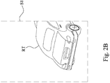
- Fig. 2B is a schematic diagram of a system for providing a simulated environment according to the embodiment of Fig. 2A .
- a first scenario S1 is illustrated in Fig. 2B .
- the first scenario S1 is an illustration of the scenario being covered by the first field of view F1 in the simulated environment.
- part of the tail of the virtual roadster RT is observable to user 1. Since user 2, which is also regard as a mobile object, is not detectable in the radar range D1, the existence of user 2 is insensible in the first scenario S1.
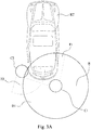
- Fig. 3A is a schematic diagram of a system for providing a simulated environment according to some embodiments of present disclosure.
- the figure illustrates an above view of a simulated environment.
- a first coordinate C1 corresponding to user 1 may be provided to the simulated environment.
- a first field of view F1 extended from the first coordinate C1 is illustrated in the figure, wherein the first field of view F1 indicates a range that user 1 may observe via the first gear 100 in the simulated environment.
- a second coordinate C2 corresponding to user 2 may be provided to the simulated environment.
- a second field of view F2 extended from the second coordinate C2 is illustrated in the figure to indicate a range that user 2 may observe in the simulated environment.
- the virtual roadster RT is provided in the center of the simulated environment.
- the first coordinate C1 is located at the rear right of the virtual roadster RT.
- the second coordinate C2 is located around rear left of the virtual roadster RT.
- the second coordinate C2 is located within the first field of view F1.
- user 1 is being provided with a radar range D1.
- the radar range D1 is a circle area with a radius R centered by the first coordinate C1. Since the first coordinate C1 is determined by the position of user 1 carrying the first gear 100, it can be say that the radar range D1 is centered by the first gear 100 as well.
- mobile objects are not observable to user 1 unless they are detectable in the radar range D1.
- the computing unit 300 may provide an indication corresponding to user 2 in the simulated environment. As such, user 1 may see the presence of user 2, which may reduce the chance for the users to have collisions.
- the radius R is determined according to height, length of arm, length of feet or step length measured from user 1. For example, for a person who has longer arms, a larger radius would be more likely to reduce the chance for having limb collisions than smaller ones.
- Fig. 3B is a schematic diagram of a system for providing a simulated environment according to the embodiment of Fig. 3A .
- a first scenario S1 is illustrated in Fig. 3B .
- the first scenario S1 is an illustration of the scenario being covered by the first field of view F1 in the simulated environment.
- part of the tail of the virtual roadster RT is observable to user 1. Since user 2, as a mobile object, is moving toward user 1 and being detected in the radar range D1 centered by the first gear 100, an avatar V2 corresponding to user 2 is illustrated next to the virtual roadster RT in the first scenario S1.
- the avatar V2 may be provided with the appearance and outfits corresponding to user 2.
- the avatar V2 may move according to the movement of user 2.
- user 1 may observe the relative distance between him and user 2. Even though user 2 is concentrating on the virtual roadster RT, user 1 may have a chance to walk past him in advance.
- the computing unit 300 stops to illustrate the avatar V2 in the first scenario S1, which may save more powers and further reduce system loadings.
- Fig. 4 is a schematic diagram of a system for providing a simulated environment according to some embodiments of present disclosure.
- present disclosure provides user 1 a radar range D1, only the mobile objects covered by the radar range D1 is observable to user 1.
- system burden and power consumption of the computing unit 300 may be reduced.
- the computing unit 300 was configured to illustrate any motion made by user 2 in simulated environment, the computing unit 300 will be repeatedly refreshing the image of the avatar V2 as long as user 2 is detectable in the radar range D1.
- an approach is provided by present disclosure to further reduce system burden and power consumption.
- the computing unit 300 is further configured only to refresh the avatar V2 corresponding to a motion of the second user 2 in the first scenario S1 when the motion is being detected as exceeding a motion threshold.
- the motion threshold is determined according to height, length of arm, length of feet or step length of user 2. As shown in Fig. 4 , when user 2 raises his hand, the motion is being detected as exceeding the motion threshold and will be presented on the avatar V2 in the first scenario S1. In this manner, user 1 may observe major motions made by user 2 but minor motions, such as eye blinks, will be filtered.
- the computing unit 300 is further configured to reduce a refresh rate (in fps) for refreshing the avatar V2 corresponding to the motion when the motion is being detected as lower than the motion threshold.
- a refresh rate in fps
- Fig. 5 is a schematic diagram of a system for providing a simulated environment according to some embodiments of present disclosure.
- present disclosure provides user 1 a radar range D1, only the mobile objects covered by the radar range D1 is observable as avatars to user 1.
- present disclosure further provides some alternatives to illustrate the presence of users covered by the radar range D1.
- a token T2 corresponding to user 2 may be presented in the first scenario S1.
- the token T2 may move according to the movement of user 2.
- user 1 may observe the relative distance between him and user 2.
- the presence of the token T2 may be presented in the first scenario S1 with some notification audios. The notification audios are provided as precautions in case user 1 ignores the presence of the token T2.
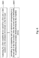
- Fig. 6 is a flow chart of a method for providing a simulated environment according to some embodiments of present disclosure. The steps of the method will be listed and explained in detail in following segments.
- Step S601 outputting, by a first wearable device, a first scenario of the simulated environment.
- the first gear 100 is configured to associate with the computing unit 300 for displaying the first scenario S1 of the simulated environment to user 1, wherein the first coordinate C1 is assigned to user 1 in the simulated environment.
- Step S602 providing, by a computing unit, an indication corresponding to a mobile object in the first scenario when the mobile object is detectable in a predetermined distance distanced from the first wearable device.
- the first gear 100 is configured to associate with the computing unit 300 for displaying the first scenario S1 of the simulated environment to user 1.
- the avatar V2 or the token T2 corresponding to user 2 may be illustrated in the first scenario S1 only when user 2, as a mobile object, is detectable within the radar range D1.
- the computing unit 300 when user 2 is no longer detectable in the radar range D1, the computing unit 300 stops to illustrate the avatar V2 or the token T2 in the first scenario S1. In some embodiments, the computing unit 300 is further configured only to refresh the avatar V2 or the token T2 corresponding to a motion of the second user 2 in the first scenario S1 when the motion is being detected as exceeding a motion threshold.
Landscapes
- Engineering & Computer Science (AREA)
- Theoretical Computer Science (AREA)
- General Engineering & Computer Science (AREA)
- Physics & Mathematics (AREA)
- General Physics & Mathematics (AREA)
- Human Computer Interaction (AREA)
- Computer Graphics (AREA)
- Computer Hardware Design (AREA)
- Software Systems (AREA)
- Multimedia (AREA)
- Processing Or Creating Images (AREA)
- User Interface Of Digital Computer (AREA)
Abstract
Description
- This application claims priority to
U.S. Provisional Application Serial Number 62/482,207, filed on April 06, 2017 - Present disclosure relates to a system and a method for providing a simulated environment. More particularly, the present disclosure relates to the system and the method for providing simulated environment.
- Virtual reality technology is an ideal way for demonstrating highly realistic objects to users, especially to those cannot be satisfied only with 2D pictures or videos. Due to the effort of engineers, nowadays, objects displayed in virtual reality world are convincing that users sometimes describe them as almost touchable. Actually, the virtual reality image displayed to a user is continuously refreshed in a very fast speed according to his/her action. The unrestful process of refreshment is the reason why users can be immersive in the virtual reality environment by acting the same in the real world.
- Furthermore, virtual reality environment is more powerful when being applied to a group of people. By sharing the same virtual space, a group of users can have observations and discussions on a common ground, which definitely makes demonstration or co-working much easier. However, there are still some unsolved problems for providing a virtual reality environment to multiple users, such as system burden or power consumption.
- The disclosure relates to a system for providing a simulated environment. The system comprises a first wearable device and a computing unit. The first wearable device is configured to output a first scenario of the simulated environment. The computing unit is configured to provide an indication corresponding to an object in the first scenario when the object is detectable in a predetermined distance distanced from the first wearable device.
- Another aspect of present disclosure is to provide a method for providing a simulated environment. The method comprises following steps: outputting, by a first wearable device, a first scenario of the simulated environment; and providing, by a computing unit, an indication corresponding to an object in the first scenario when the object is detectable in a predetermined distance distanced from the first wearable device.
- It is to be understood that both the foregoing general description and the following detailed description are by examples, and are intended to provide further explanation of the disclosure as claimed.
- Present disclosure can be more fully understood by reading the following detailed description of the embodiment, with reference made to the accompanying drawings as follows:
-
Fig. 1 is a schematic diagram for showing the backgrounds of an embodiment of present disclosure; -
Fig. 2A is a schematic diagram of a system for providing a simulated environment according to some embodiments of present disclosure; -
Fig. 2B is a schematic diagram of a system for providing a simulated environment according to the embodiment ofFig. 2A ; -
Fig. 3A is a schematic diagram of a system for providing a simulated environment according to some embodiments of present disclosure; -
Fig. 3B is a schematic diagram of a system for providing a simulated environment according to the embodiment ofFig. 3A ; -
Fig. 4 is a schematic diagram of a system for providing a simulated environment according to some embodiments of present disclosure; -
Fig. 5 is a schematic diagram of a system for providing a simulated environment according to some embodiments of present disclosure; and -
Fig. 6 is a flow chart of a method for providing a simulated environment according to some embodiments of present disclosure. - Reference will now be made in detail to the present embodiments of the disclosure, examples of which are illustrated in the accompanying drawings. Wherever possible, the same reference numbers are used in the drawings and the description to refer to the same or like parts.
- The terms used in this specification generally have their ordinary meanings in the art and in the specific context where each term is used. The use of examples in this specification, including examples of any terms discussed herein, is illustrative only, and in no way limits the scope and meaning of the disclosure or of any exemplified term. Likewise, the present disclosure is not limited to various embodiments given in this specification.
- As used herein, the terms "comprising," "including," "having," and the like are to be understood to be open-ended, i.e., to mean including but not limited to.
- Reference throughout the specification to "one embodiment" or "an embodiment" means that a particular feature, structure, implementation, or characteristic described in connection with the embodiment is included in at least one embodiment of the present disclosure. Thus, uses of the phrases "in one embodiment" or "in an embodiment" in various places throughout the specification are not necessarily all referring to the same embodiment. Furthermore, the particular features, structures, implementation, or characteristics may be combined in any suitable manner in one or more embodiments.
- In the following description and claims, the terms "coupled" and "connected", along with their derivatives, may be used. In particular embodiments, "connected" and "coupled" may be used to indicate that two or more elements are in direct physical or electrical contact with each other, or may also mean that two or more elements may be in indirect contact with each other. "Coupled" and "connected" may still be used to indicate that two or more elements cooperate or interact with each other.
-
Fig. 1 is a schematic diagram for showing the backgrounds of an embodiment of present disclosure. As shown inFig. 1 , in the embodiment, a virtual reality demonstration is provided in an exhibition room.User 1 and user 2 are the participants of the virtual reality demonstration. Since the demonstration is regarding to a new car, therefore a virtual roadster RT would be illustrated in a simulated environment. The simulated environment mentioned here is constructed by one or several computing units to generate realistic images, sounds and other sensations that simulate the user's physical presence in the simulated environment. For example, the simulated environment can be a virtual reality (VR) space, augmented reality (AR) space or mixed reality (MR) space. In this case, it is a virtual reality space. The virtual roadster RT illustrated inFig. 1 is merely an indication for showing the position of the virtual roadster RT in the simulated environment, the virtual roadster RT is not perceivable untiluser 1 and user 2 wears corresponding gears. During the virtual reality demonstration,user 1 may carry afirst gear 100 and the user 2 may carry asecond gear 200, wherein thefirst gear 100 and thesecond gear 200 are both HMDs (Head-Mounted Displays). Thefirst gear 100 and thesecond gear 200 are in communication with acomputing unit 300, wherein thecomputing unit 300 is configured to provide the simulated environment. Thefirst gear 100 is configured to output a first scenario of the simulated environment touser 1. The first scenario being output shows a partial view of the virtual reality space corresponding to the viewpoint of thefirst gear 100. Thesecond gear 200 is configured to output a second scenario of the simulated environment to user 2. The second scenario being output shows another partial view of the virtual reality space corresponding to the viewpoint of thesecond gear 200. Part of the virtual roadster RT may be provided in the first scenario depending on the position ofuser 1 with respect to the exhibition room. In the same manner, part of the virtual roadster RT may be provided in the second scenario depends on the position of user 2 with respect to the exhibition room. - In some configurations of the embodiment, the
first gear 100 may track a first position corresponding touser 1 and send the first position to thecomputing unit 300. Thesecond gear 200 may track a second position corresponding to user 2 and send the second position to thecomputing unit 300. The first position and the second position are provided to generate the coordinates corresponding touser 1 and user 2 in the simulated environment respectively. - In some other configurations of the embodiment, only the
first gear 100 may track a first position corresponding touser 1 and a second position corresponding to user 2. Thefirst gear 100 may send the first position and the second position to thecomputing unit 300. The first position and the second position are provided to generate the coordinates corresponding touser 1 and user 2 in the simulated environment respectively. - In some other configurations of the embodiment, an individual detector (not shown in figure) may be configured to track a first position corresponding to
user 1 and a second position corresponding to user 2. The individual detector may send the first position and the second position to thecomputing unit 300. The first position and the second position are provided to generate the coordinates corresponding touser 1 and user 2 in the simulated environment respectively. - In aforementioned embodiments, since the exhibition room is a limited space, it highly possible that
user 1 and user 2 would bump into each other if they were focus on the virtual roadster RT. A straightforward approach to solve aforementioned problem is to make all the users visible in the simulated environment. If the users of the simulated environment may see each other, it would be less likely to have collisions with other users in the exhibition room. Moreover, it would be convenient to have interactions with the others if they can be seen in the simulated environment. However, the approach of keeping all the users visible in the simulated environment according to the perspective of users necessitates high rate frame refreshments, which is no doubt a heavy burden to the system for providing the simulated environment. Therefore, present disclosure provides a proper resolution. - However, it should be noted, the
computing unit 300 illustrated inFig. 1 is only an example. In some embodiments, thecomputing unit 300 may be a CPU, GPU, or some control unit configured in thefirst gear 100 or thesecond gear 200. Depends on which gear is configured with thecomputing unit 300, the first position corresponding touser 1 and the second position corresponding to user 2 will be sent to that gear and being processed by thecomputing unit 300. -
Fig. 2A is a schematic diagram of a system for providing a simulated environment according to some embodiments of present disclosure. The figure illustrates an above view of a simulated environment. As shown inFig. 1 , in the embodiment, a virtual roadster RT is provided in the center of the simulated environment. Whenuser 1 is carrying thefirst gear 100, a first coordinate C1 corresponding touser 1 may be provided to the simulated environment. The first coordinate C1 is located at the rear right of the virtual roadster RT. A first field of view F1 extended from the first coordinate C1 is illustrated in the figure, wherein the first field of view F1 indicates a range thatuser 1 may observe in the simulated environment. In the same manner, when user 2 is carrying thesecond gear 200, a second coordinate C2 corresponding to user 2 may be provided to the simulated environment. The second coordinate C2 is located at the left lateral of the virtual roadster RT. A second field of view F2 extended from the second coordinate C2 is illustrated in the figure to indicate a range that user 2 may observe in the simulated environment. - In the embodiment,
user 1 is being provided with a radar range D1. The radar range D1 is a circle area with a radius R centered by the first coordinate C1. Since the first coordinate C1 is determined by the position ofuser 1 carrying thefirst gear 100, it can be say that the radar range is centered by thefirst gear 100 as well. In the simulated environment, mobile objects are not observable touser 1 unless they are detectable in the radar range D1. -
Fig. 2B is a schematic diagram of a system for providing a simulated environment according to the embodiment ofFig. 2A . A first scenario S1 is illustrated inFig. 2B . As shown inFig. 1 , via thefirst gear 100,user 1 may observe the first scenario S1 provided bycomputing unit 300. The first scenario S1 is an illustration of the scenario being covered by the first field of view F1 in the simulated environment. As shown inFig. 2B , in the first scenario S1, part of the tail of the virtual roadster RT is observable touser 1. Since user 2, which is also regard as a mobile object, is not detectable in the radar range D1, the existence of user 2 is insensible in the first scenario S1. -
Fig. 3A is a schematic diagram of a system for providing a simulated environment according to some embodiments of present disclosure. The figure illustrates an above view of a simulated environment. As shown in bothFig. 1 andFig. 3A , in the embodiment, whenuser 1 is carrying thefirst gear 100, a first coordinate C1 corresponding touser 1 may be provided to the simulated environment. A first field of view F1 extended from the first coordinate C1 is illustrated in the figure, wherein the first field of view F1 indicates a range thatuser 1 may observe via thefirst gear 100 in the simulated environment. In the same manner, when user 2 is carrying thesecond gear 200, a second coordinate C2 corresponding to user 2 may be provided to the simulated environment. A second field of view F2 extended from the second coordinate C2 is illustrated in the figure to indicate a range that user 2 may observe in the simulated environment. The virtual roadster RT is provided in the center of the simulated environment. The first coordinate C1 is located at the rear right of the virtual roadster RT. The second coordinate C2 is located around rear left of the virtual roadster RT. The second coordinate C2 is located within the first field of view F1. - In the embodiment,
user 1 is being provided with a radar range D1. The radar range D1 is a circle area with a radius R centered by the first coordinate C1. Since the first coordinate C1 is determined by the position ofuser 1 carrying thefirst gear 100, it can be say that the radar range D1 is centered by thefirst gear 100 as well. In the simulated environment, mobile objects are not observable touser 1 unless they are detectable in the radar range D1. When user 2, as a mobile object, is moving towarduser 1 and being detected in a distance shorter than the radius R from thefirst gear 100, thecomputing unit 300 may provide an indication corresponding to user 2 in the simulated environment. As such,user 1 may see the presence of user 2, which may reduce the chance for the users to have collisions. - In the embodiment, the radius R is determined according to height, length of arm, length of feet or step length measured from
user 1. For example, for a person who has longer arms, a larger radius would be more likely to reduce the chance for having limb collisions than smaller ones. -
Fig. 3B is a schematic diagram of a system for providing a simulated environment according to the embodiment ofFig. 3A . A first scenario S1 is illustrated inFig. 3B . As shown in bothFig. 1 andFig. 3 , via thefirst gear 100,user 1 may observe the first scenario S1 provided by thecomputing unit 300. The first scenario S1 is an illustration of the scenario being covered by the first field of view F1 in the simulated environment. In the first scenario S1, part of the tail of the virtual roadster RT is observable touser 1. Since user 2, as a mobile object, is moving towarduser 1 and being detected in the radar range D1 centered by thefirst gear 100, an avatar V2 corresponding to user 2 is illustrated next to the virtual roadster RT in the first scenario S1. The avatar V2 may be provided with the appearance and outfits corresponding to user 2. The avatar V2 may move according to the movement of user 2. As such,user 1 may observe the relative distance between him and user 2. Even though user 2 is concentrating on the virtual roadster RT,user 1 may have a chance to walk past him in advance. In some embodiments, when user 2 is no longer detectable in the radar range D1, thecomputing unit 300 stops to illustrate the avatar V2 in the first scenario S1, which may save more powers and further reduce system loadings. -
Fig. 4 is a schematic diagram of a system for providing a simulated environment according to some embodiments of present disclosure. As shown inFig. 3A andFig. 3B , present disclosure provides user 1 a radar range D1, only the mobile objects covered by the radar range D1 is observable touser 1. Through this approach, system burden and power consumption of thecomputing unit 300 may be reduced. Nevertheless, if thecomputing unit 300 was configured to illustrate any motion made by user 2 in simulated environment, thecomputing unit 300 will be repeatedly refreshing the image of the avatar V2 as long as user 2 is detectable in the radar range D1. According toFig. 3A andFig. 3B , an approach is provided by present disclosure to further reduce system burden and power consumption. In some embodiments, thecomputing unit 300 is further configured only to refresh the avatar V2 corresponding to a motion of the second user 2 in the first scenario S1 when the motion is being detected as exceeding a motion threshold. The motion threshold is determined according to height, length of arm, length of feet or step length of user 2. As shown inFig. 4 , when user 2 raises his hand, the motion is being detected as exceeding the motion threshold and will be presented on the avatar V2 in the first scenario S1. In this manner,user 1 may observe major motions made by user 2 but minor motions, such as eye blinks, will be filtered. Moreover, in some embodiments, thecomputing unit 300 is further configured to reduce a refresh rate (in fps) for refreshing the avatar V2 corresponding to the motion when the motion is being detected as lower than the motion threshold. Through these approaches, system burden and power consumption of thecomputing unit 300 may be reduced further. -
Fig. 5 is a schematic diagram of a system for providing a simulated environment according to some embodiments of present disclosure. As shown inFig. 3A andFig. 3B , present disclosure provides user 1 a radar range D1, only the mobile objects covered by the radar range D1 is observable as avatars touser 1. However, present disclosure further provides some alternatives to illustrate the presence of users covered by the radar range D1. As shown inFig. 5 , if user 2, as a mobile object, is being detected in the radar range D1, a token T2 corresponding to user 2 may be presented in the first scenario S1. The token T2 may move according to the movement of user 2. As such,user 1 may observe the relative distance between him and user 2. In some embodiments, the presence of the token T2 may be presented in the first scenario S1 with some notification audios. The notification audios are provided as precautions incase user 1 ignores the presence of the token T2. -
Fig. 6 is a flow chart of a method for providing a simulated environment according to some embodiments of present disclosure. The steps of the method will be listed and explained in detail in following segments. - Step S601: outputting, by a first wearable device, a first scenario of the simulated environment. As shown in
Fig. 1 ,Fig. 2A ,Fig. 2B ,Fig. 3A ,Fig. 3B, Fig. 4 and Fig. 5 , thefirst gear 100 is configured to associate with thecomputing unit 300 for displaying the first scenario S1 of the simulated environment touser 1, wherein the first coordinate C1 is assigned touser 1 in the simulated environment. - Step S602: providing, by a computing unit, an indication corresponding to a mobile object in the first scenario when the mobile object is detectable in a predetermined distance distanced from the first wearable device. As shown in
Fig. 1 ,Fig. 2A ,Fig. 2B ,Fig. 3A ,Fig. 3B, Fig. 4 and Fig. 5 , thefirst gear 100 is configured to associate with thecomputing unit 300 for displaying the first scenario S1 of the simulated environment touser 1. The avatar V2 or the token T2 corresponding to user 2 may be illustrated in the first scenario S1 only when user 2, as a mobile object, is detectable within the radar range D1. In some embodiments, when user 2 is no longer detectable in the radar range D1, thecomputing unit 300 stops to illustrate the avatar V2 or the token T2 in the first scenario S1. In some embodiments, thecomputing unit 300 is further configured only to refresh the avatar V2 or the token T2 corresponding to a motion of the second user 2 in the first scenario S1 when the motion is being detected as exceeding a motion threshold. Through these approaches, present disclosure provides ideal resolutions to reduce system loadings and power consumption for providing simulated environments to multiple users. - Although the present disclosure has been described in considerable detail with reference to certain embodiments thereof, other embodiments are possible. Therefore, the spirit and scope of the appended claims should not be limited to the description of the embodiments contained herein.
- It will be apparent to those skilled in the art that various modifications and variations can be made to the structure of the present disclosure without departing from the scope or spirit of the disclosure. In view of the foregoing, it is intended that the present disclosure cover modifications and variations of this disclosure provided they fall within the scope of the following claims.
Claims (15)
- A system for providing a simulated environment, comprising:a first wearable device, configured to output a first scenario of the simulated environment; anda computing unit, configured to provide an indication corresponding to an object in the first scenario when the object is detectable in a predetermined distance distanced from the first wearable device.
- The system of claim 1, wherein the indication is an avatar corresponding to the object.
- The system of any one of the preceding claims, wherein the computing unit stops to illustrate the avatar in the first scenario when the object is no longer detectable in the predetermined distance distanced from the first wearable device.
- The system of any one of the preceding claims, wherein the computing unit stops to refresh the avatar in the first scenario when the object is no longer detectable in the predetermined distance distanced from the first wearable device.
- The system of any one of the preceding claims, wherein the computing unit is further configured to refresh the avatar corresponding to a motion of the object in the first scenario when the motion is being detected exceeding a motion threshold.
- The system of claim 5, wherein the motion threshold is determined according to height, length of arm, length of feet or step length of the object.
- The system of claim 5, wherein the computing unit is further configured to reduce a refresh rate for refreshing the avatar corresponding to the motion when the motion is being detected lowering the motion threshold.
- A method for providing a simulated environment, comprising:outputting, by a first wearable device, a first scenario of the simulated environment; andproviding, by a computing unit, an indication corresponding to a mobile object in the first scenario when the mobile object is detectable in a predetermined distance distanced from the first wearable device.
- The method of claim 8, wherein the indication is an avatar corresponding to the mobile object.
- The method of any one of the preceding claims 8 to 9, further comprising:stopping, by the computing unit, to illustrate the avatar in the first scenario when the mobile object is no longer detectable in the predetermined distance distanced from the first wearable device.
- The method of any one of the preceding claims 8 to 10, further comprising:stopping, by the computing unit, to refresh the avatar in the first scenario when the mobile object is no longer detectable in the predetermined distance distanced from the first wearable device.
- The method of any one of the preceding claims 8 to 11, further comprising:refreshing, by the computing unit, the avatar corresponding to a motion of the mobile object in the first scenario when the motion is being detected exceeding a motion threshold.
- The method of claim 12, wherein the motion threshold is determined according to height, length of arm, length of feet or step length of the mobile object.
- The method of claim 12, further comprising:reducing, by the computing unit, a refresh rate for refreshing the avatar corresponding to the motion when the motion is being detected lowering the motion threshold.
- The method of any one of the preceding claims 8 to 14, wherein the predetermined distance is determined according to height, length of arm, length of feet or step length measured from a user who carries the first wearable device.
Applications Claiming Priority (2)
| Application Number | Priority Date | Filing Date | Title |
|---|---|---|---|
| US201762482207P | 2017-04-06 | 2017-04-06 | |
| US15/842,832 US10713848B2 (en) | 2017-04-06 | 2017-12-14 | System and method for providing simulated environment |
Publications (2)
| Publication Number | Publication Date |
|---|---|
| EP3385823A1 true EP3385823A1 (en) | 2018-10-10 |
| EP3385823B1 EP3385823B1 (en) | 2021-06-16 |
Family
ID=61198667
Family Applications (1)
| Application Number | Title | Priority Date | Filing Date |
|---|---|---|---|
| EP18153849.7A Active EP3385823B1 (en) | 2017-04-06 | 2018-01-29 | System and method for providing simulated environment |
Country Status (4)
| Country | Link |
|---|---|
| US (1) | US10713848B2 (en) |
| EP (1) | EP3385823B1 (en) |
| CN (1) | CN108693966B (en) |
| TW (1) | TWI674532B (en) |
Families Citing this family (1)
| Publication number | Priority date | Publication date | Assignee | Title |
|---|---|---|---|---|
| KR102782794B1 (en) * | 2018-12-26 | 2025-03-19 | 삼성전자주식회사 | Method and wearable device for identifying hand of truly user |
Citations (4)
| Publication number | Priority date | Publication date | Assignee | Title |
|---|---|---|---|---|
| US20130328928A1 (en) * | 2012-06-12 | 2013-12-12 | Sony Computer Entertainment Inc. | Obstacle avoidance apparatus and obstacle avoidance method |
| US20150094142A1 (en) * | 2013-09-30 | 2015-04-02 | Sony Computer Entertainment Inc. | Camera based safety mechanisms for users of head mounted displays |
| US20160282618A1 (en) * | 2013-12-19 | 2016-09-29 | Sony Corporation | Image display device and image display method |
| US20170219822A1 (en) * | 2014-11-04 | 2017-08-03 | Sony Interactive Entertainment Inc. | Head mounted display and information processing method |
Family Cites Families (13)
| Publication number | Priority date | Publication date | Assignee | Title |
|---|---|---|---|---|
| JP2012150761A (en) * | 2011-01-21 | 2012-08-09 | Fujitsu Ltd | Information processing device and information processing program |
| EP3654146A1 (en) * | 2011-03-29 | 2020-05-20 | QUALCOMM Incorporated | Anchoring virtual images to real world surfaces in augmented reality systems |
| US10955665B2 (en) | 2013-06-18 | 2021-03-23 | Microsoft Technology Licensing, Llc | Concurrent optimal viewing of virtual objects |
| US9575319B2 (en) * | 2014-03-10 | 2017-02-21 | Ion Virtual Technology Corporation | Method and system for reducing motion blur when experiencing virtual or augmented reality environments |
| US9542718B2 (en) | 2014-12-18 | 2017-01-10 | Intel Corporation | Head mounted display update buffer |
| CN105204625B (en) | 2015-08-31 | 2018-05-08 | 小米科技有限责任公司 | Safety protection method and device in reality-virtualizing game |
| US20170232335A1 (en) * | 2016-02-05 | 2017-08-17 | Prizm Labs, Inc. | Physical/virtual game system and methods for manipulating virtual objects within a virtual game environment |
| US10099122B2 (en) * | 2016-03-30 | 2018-10-16 | Sony Interactive Entertainment Inc. | Head-mounted display tracking |
| CN105912444A (en) * | 2016-04-29 | 2016-08-31 | 网易(杭州)网络有限公司 | Refresh rate testing method and device of picture change of mobile terminal game screen |
| CN106295581A (en) | 2016-08-15 | 2017-01-04 | 联想(北京)有限公司 | Obstacle detection method, device and virtual reality device |
| CN106384374A (en) | 2016-09-27 | 2017-02-08 | 郑州云海信息技术有限公司 | Method and device for realizing animation effect |
| CN106484119A (en) * | 2016-10-24 | 2017-03-08 | 网易(杭州)网络有限公司 | Virtual reality system and virtual reality system input method |
| CN106383596B (en) | 2016-11-15 | 2023-08-29 | 北京当红齐天国际文化科技发展集团有限公司 | Virtual reality anti-dizzy system and method based on space positioning |
-
2017
- 2017-12-14 US US15/842,832 patent/US10713848B2/en active Active
-
2018
- 2018-01-29 EP EP18153849.7A patent/EP3385823B1/en active Active
- 2018-02-01 TW TW107103678A patent/TWI674532B/en active
- 2018-02-05 CN CN201810112649.0A patent/CN108693966B/en active Active
Patent Citations (4)
| Publication number | Priority date | Publication date | Assignee | Title |
|---|---|---|---|---|
| US20130328928A1 (en) * | 2012-06-12 | 2013-12-12 | Sony Computer Entertainment Inc. | Obstacle avoidance apparatus and obstacle avoidance method |
| US20150094142A1 (en) * | 2013-09-30 | 2015-04-02 | Sony Computer Entertainment Inc. | Camera based safety mechanisms for users of head mounted displays |
| US20160282618A1 (en) * | 2013-12-19 | 2016-09-29 | Sony Corporation | Image display device and image display method |
| US20170219822A1 (en) * | 2014-11-04 | 2017-08-03 | Sony Interactive Entertainment Inc. | Head mounted display and information processing method |
Also Published As
| Publication number | Publication date |
|---|---|
| TWI674532B (en) | 2019-10-11 |
| CN108693966A (en) | 2018-10-23 |
| US10713848B2 (en) | 2020-07-14 |
| TW201837707A (en) | 2018-10-16 |
| EP3385823B1 (en) | 2021-06-16 |
| CN108693966B (en) | 2020-09-18 |
| US20180293800A1 (en) | 2018-10-11 |
Similar Documents
| Publication | Publication Date | Title |
|---|---|---|
| McGill et al. | Challenges in passenger use of mixed reality headsets in cars and other transportation | |
| Marquardt et al. | Comparing non-visual and visual guidance methods for narrow field of view augmented reality displays | |
| Nayyar et al. | Virtual Reality (VR) & Augmented Reality (AR) technologies for tourism and hospitality industry | |
| Kaul et al. | Haptichead: A spherical vibrotactile grid around the head for 3d guidance in virtual and augmented reality | |
| Cho et al. | RideVR: Reducing sickness for in-car virtual reality by mixed-in presentation of motion flow information | |
| AU2017204739B2 (en) | Massive simultaneous remote digital presence world | |
| US9996975B2 (en) | Interactive multi-rider virtual reality ride system | |
| US11836282B2 (en) | Method and device for surfacing physical environment interactions during simulated reality sessions | |
| JP2022545851A (en) | VIRTUAL OBJECT CONTROL METHOD AND APPARATUS, DEVICE, COMPUTER-READABLE STORAGE MEDIUM | |
| Sra et al. | Metaspace: Full-body tracking for immersive multiperson virtual reality | |
| TWI758869B (en) | Interactive object driving method, apparatus, device, and computer readable storage meidum | |
| McGill et al. | Augmented, virtual and mixed reality passenger experiences | |
| TWI453462B (en) | Telescopic observation for virtual reality system and method thereof using intelligent electronic device | |
| CN108830944A (en) | Optical perspective formula three-dimensional near-eye display system and display methods | |
| US20200097707A1 (en) | Camera Module and Extended Reality System Using the Same | |
| Lou et al. | Reducing cybersickness by geometry deformation | |
| US10713848B2 (en) | System and method for providing simulated environment | |
| Taqvi | Reality and perception: Utilization of many facets of augmented reality | |
| Kosch et al. | Exploring the optimal point of view in third person out-of-body experiences | |
| Suma et al. | Sharing space in mixed and virtual reality environments using a low-cost depth sensor | |
| Narumi et al. | Digital railway museum: An approach to introduction of digital exhibition systems at the railway museum | |
| Techasarntikul et al. | Evaluation of Embodied Agent Positioning and Moving Interfaces for an AR Virtual Guide. | |
| JP2022183943A (en) | Content delivery system, content delivery method, and content delivery program | |
| JP2023030298A (en) | Sign-of-presence presentation device | |
| KR20180112478A (en) | Method and apparatus for processing 3-dimension image |
Legal Events
| Date | Code | Title | Description |
|---|---|---|---|
| PUAI | Public reference made under article 153(3) epc to a published international application that has entered the european phase |
Free format text: ORIGINAL CODE: 0009012 |
|
| STAA | Information on the status of an ep patent application or granted ep patent |
Free format text: STATUS: REQUEST FOR EXAMINATION WAS MADE |
|
| 17P | Request for examination filed |
Effective date: 20180129 |
|
| AK | Designated contracting states |
Kind code of ref document: A1 Designated state(s): AL AT BE BG CH CY CZ DE DK EE ES FI FR GB GR HR HU IE IS IT LI LT LU LV MC MK MT NL NO PL PT RO RS SE SI SK SM TR |
|
| AX | Request for extension of the european patent |
Extension state: BA ME |
|
| RBV | Designated contracting states (corrected) |
Designated state(s): AL AT BE BG CH CY CZ DE DK EE ES FI FR GB GR HR HU IE IS IT LI LT LU LV MC MK MT NL NO PL PT RO RS SE SI SK SM TR |
|
| GRAP | Despatch of communication of intention to grant a patent |
Free format text: ORIGINAL CODE: EPIDOSNIGR1 |
|
| STAA | Information on the status of an ep patent application or granted ep patent |
Free format text: STATUS: GRANT OF PATENT IS INTENDED |
|
| INTG | Intention to grant announced |
Effective date: 20210223 |
|
| RIN1 | Information on inventor provided before grant (corrected) |
Inventor name: LEE, CHING-HAO Inventor name: LEE, HSIN-HAO |
|
| GRAS | Grant fee paid |
Free format text: ORIGINAL CODE: EPIDOSNIGR3 |
|
| GRAA | (expected) grant |
Free format text: ORIGINAL CODE: 0009210 |
|
| STAA | Information on the status of an ep patent application or granted ep patent |
Free format text: STATUS: THE PATENT HAS BEEN GRANTED |
|
| AK | Designated contracting states |
Kind code of ref document: B1 Designated state(s): AL AT BE BG CH CY CZ DE DK EE ES FI FR GB GR HR HU IE IS IT LI LT LU LV MC MK MT NL NO PL PT RO RS SE SI SK SM TR |
|
| REG | Reference to a national code |
Ref country code: GB Ref legal event code: FG4D |
|
| REG | Reference to a national code |
Ref country code: CH Ref legal event code: EP |
|
| REG | Reference to a national code |
Ref country code: DE Ref legal event code: R096 Ref document number: 602018018522 Country of ref document: DE |
|
| REG | Reference to a national code |
Ref country code: AT Ref legal event code: REF Ref document number: 1402881 Country of ref document: AT Kind code of ref document: T Effective date: 20210715 |
|
| REG | Reference to a national code |
Ref country code: IE Ref legal event code: FG4D |
|
| REG | Reference to a national code |
Ref country code: NL Ref legal event code: FP |
|
| REG | Reference to a national code |
Ref country code: LT Ref legal event code: MG9D |
|
| PG25 | Lapsed in a contracting state [announced via postgrant information from national office to epo] |
Ref country code: LT Free format text: LAPSE BECAUSE OF FAILURE TO SUBMIT A TRANSLATION OF THE DESCRIPTION OR TO PAY THE FEE WITHIN THE PRESCRIBED TIME-LIMIT Effective date: 20210616 Ref country code: FI Free format text: LAPSE BECAUSE OF FAILURE TO SUBMIT A TRANSLATION OF THE DESCRIPTION OR TO PAY THE FEE WITHIN THE PRESCRIBED TIME-LIMIT Effective date: 20210616 Ref country code: BG Free format text: LAPSE BECAUSE OF FAILURE TO SUBMIT A TRANSLATION OF THE DESCRIPTION OR TO PAY THE FEE WITHIN THE PRESCRIBED TIME-LIMIT Effective date: 20210916 Ref country code: HR Free format text: LAPSE BECAUSE OF FAILURE TO SUBMIT A TRANSLATION OF THE DESCRIPTION OR TO PAY THE FEE WITHIN THE PRESCRIBED TIME-LIMIT Effective date: 20210616 |
|
| REG | Reference to a national code |
Ref country code: AT Ref legal event code: MK05 Ref document number: 1402881 Country of ref document: AT Kind code of ref document: T Effective date: 20210616 |
|
| PG25 | Lapsed in a contracting state [announced via postgrant information from national office to epo] |
Ref country code: LV Free format text: LAPSE BECAUSE OF FAILURE TO SUBMIT A TRANSLATION OF THE DESCRIPTION OR TO PAY THE FEE WITHIN THE PRESCRIBED TIME-LIMIT Effective date: 20210616 Ref country code: NO Free format text: LAPSE BECAUSE OF FAILURE TO SUBMIT A TRANSLATION OF THE DESCRIPTION OR TO PAY THE FEE WITHIN THE PRESCRIBED TIME-LIMIT Effective date: 20210916 Ref country code: SE Free format text: LAPSE BECAUSE OF FAILURE TO SUBMIT A TRANSLATION OF THE DESCRIPTION OR TO PAY THE FEE WITHIN THE PRESCRIBED TIME-LIMIT Effective date: 20210616 Ref country code: RS Free format text: LAPSE BECAUSE OF FAILURE TO SUBMIT A TRANSLATION OF THE DESCRIPTION OR TO PAY THE FEE WITHIN THE PRESCRIBED TIME-LIMIT Effective date: 20210616 Ref country code: GR Free format text: LAPSE BECAUSE OF FAILURE TO SUBMIT A TRANSLATION OF THE DESCRIPTION OR TO PAY THE FEE WITHIN THE PRESCRIBED TIME-LIMIT Effective date: 20210917 |
|
| PG25 | Lapsed in a contracting state [announced via postgrant information from national office to epo] |
Ref country code: CZ Free format text: LAPSE BECAUSE OF FAILURE TO SUBMIT A TRANSLATION OF THE DESCRIPTION OR TO PAY THE FEE WITHIN THE PRESCRIBED TIME-LIMIT Effective date: 20210616 Ref country code: AT Free format text: LAPSE BECAUSE OF FAILURE TO SUBMIT A TRANSLATION OF THE DESCRIPTION OR TO PAY THE FEE WITHIN THE PRESCRIBED TIME-LIMIT Effective date: 20210616 Ref country code: PT Free format text: LAPSE BECAUSE OF FAILURE TO SUBMIT A TRANSLATION OF THE DESCRIPTION OR TO PAY THE FEE WITHIN THE PRESCRIBED TIME-LIMIT Effective date: 20211018 Ref country code: RO Free format text: LAPSE BECAUSE OF FAILURE TO SUBMIT A TRANSLATION OF THE DESCRIPTION OR TO PAY THE FEE WITHIN THE PRESCRIBED TIME-LIMIT Effective date: 20210616 Ref country code: SK Free format text: LAPSE BECAUSE OF FAILURE TO SUBMIT A TRANSLATION OF THE DESCRIPTION OR TO PAY THE FEE WITHIN THE PRESCRIBED TIME-LIMIT Effective date: 20210616 Ref country code: SM Free format text: LAPSE BECAUSE OF FAILURE TO SUBMIT A TRANSLATION OF THE DESCRIPTION OR TO PAY THE FEE WITHIN THE PRESCRIBED TIME-LIMIT Effective date: 20210616 Ref country code: ES Free format text: LAPSE BECAUSE OF FAILURE TO SUBMIT A TRANSLATION OF THE DESCRIPTION OR TO PAY THE FEE WITHIN THE PRESCRIBED TIME-LIMIT Effective date: 20210616 Ref country code: EE Free format text: LAPSE BECAUSE OF FAILURE TO SUBMIT A TRANSLATION OF THE DESCRIPTION OR TO PAY THE FEE WITHIN THE PRESCRIBED TIME-LIMIT Effective date: 20210616 |
|
| PG25 | Lapsed in a contracting state [announced via postgrant information from national office to epo] |
Ref country code: PL Free format text: LAPSE BECAUSE OF FAILURE TO SUBMIT A TRANSLATION OF THE DESCRIPTION OR TO PAY THE FEE WITHIN THE PRESCRIBED TIME-LIMIT Effective date: 20210616 |
|
| REG | Reference to a national code |
Ref country code: DE Ref legal event code: R097 Ref document number: 602018018522 Country of ref document: DE |
|
| PLBE | No opposition filed within time limit |
Free format text: ORIGINAL CODE: 0009261 |
|
| STAA | Information on the status of an ep patent application or granted ep patent |
Free format text: STATUS: NO OPPOSITION FILED WITHIN TIME LIMIT |
|
| PG25 | Lapsed in a contracting state [announced via postgrant information from national office to epo] |
Ref country code: DK Free format text: LAPSE BECAUSE OF FAILURE TO SUBMIT A TRANSLATION OF THE DESCRIPTION OR TO PAY THE FEE WITHIN THE PRESCRIBED TIME-LIMIT Effective date: 20210616 |
|
| 26N | No opposition filed |
Effective date: 20220317 |
|
| PG25 | Lapsed in a contracting state [announced via postgrant information from national office to epo] |
Ref country code: AL Free format text: LAPSE BECAUSE OF FAILURE TO SUBMIT A TRANSLATION OF THE DESCRIPTION OR TO PAY THE FEE WITHIN THE PRESCRIBED TIME-LIMIT Effective date: 20210616 |
|
| PG25 | Lapsed in a contracting state [announced via postgrant information from national office to epo] |
Ref country code: IT Free format text: LAPSE BECAUSE OF FAILURE TO SUBMIT A TRANSLATION OF THE DESCRIPTION OR TO PAY THE FEE WITHIN THE PRESCRIBED TIME-LIMIT Effective date: 20210616 |
|
| PG25 | Lapsed in a contracting state [announced via postgrant information from national office to epo] |
Ref country code: MC Free format text: LAPSE BECAUSE OF FAILURE TO SUBMIT A TRANSLATION OF THE DESCRIPTION OR TO PAY THE FEE WITHIN THE PRESCRIBED TIME-LIMIT Effective date: 20210616 |
|
| REG | Reference to a national code |
Ref country code: CH Ref legal event code: PL |
|
| REG | Reference to a national code |
Ref country code: BE Ref legal event code: MM Effective date: 20220131 |
|
| PG25 | Lapsed in a contracting state [announced via postgrant information from national office to epo] |
Ref country code: LU Free format text: LAPSE BECAUSE OF NON-PAYMENT OF DUE FEES Effective date: 20220129 |
|
| PG25 | Lapsed in a contracting state [announced via postgrant information from national office to epo] |
Ref country code: BE Free format text: LAPSE BECAUSE OF NON-PAYMENT OF DUE FEES Effective date: 20220131 |
|
| PG25 | Lapsed in a contracting state [announced via postgrant information from national office to epo] |
Ref country code: LI Free format text: LAPSE BECAUSE OF NON-PAYMENT OF DUE FEES Effective date: 20220131 Ref country code: CH Free format text: LAPSE BECAUSE OF NON-PAYMENT OF DUE FEES Effective date: 20220131 |
|
| PG25 | Lapsed in a contracting state [announced via postgrant information from national office to epo] |
Ref country code: IE Free format text: LAPSE BECAUSE OF NON-PAYMENT OF DUE FEES Effective date: 20220129 |
|
| REG | Reference to a national code |
Ref country code: DE Ref legal event code: R082 Ref document number: 602018018522 Country of ref document: DE Representative=s name: WAGNER & GEYER PARTNERSCHAFT MBB PATENT- UND R, DE |
|
| P01 | Opt-out of the competence of the unified patent court (upc) registered |
Effective date: 20230602 |
|
| PG25 | Lapsed in a contracting state [announced via postgrant information from national office to epo] |
Ref country code: HU Free format text: LAPSE BECAUSE OF FAILURE TO SUBMIT A TRANSLATION OF THE DESCRIPTION OR TO PAY THE FEE WITHIN THE PRESCRIBED TIME-LIMIT; INVALID AB INITIO Effective date: 20180129 |
|
| PG25 | Lapsed in a contracting state [announced via postgrant information from national office to epo] |
Ref country code: MK Free format text: LAPSE BECAUSE OF FAILURE TO SUBMIT A TRANSLATION OF THE DESCRIPTION OR TO PAY THE FEE WITHIN THE PRESCRIBED TIME-LIMIT Effective date: 20210616 Ref country code: CY Free format text: LAPSE BECAUSE OF FAILURE TO SUBMIT A TRANSLATION OF THE DESCRIPTION OR TO PAY THE FEE WITHIN THE PRESCRIBED TIME-LIMIT Effective date: 20210616 |
|
| PG25 | Lapsed in a contracting state [announced via postgrant information from national office to epo] |
Ref country code: MT Free format text: LAPSE BECAUSE OF FAILURE TO SUBMIT A TRANSLATION OF THE DESCRIPTION OR TO PAY THE FEE WITHIN THE PRESCRIBED TIME-LIMIT Effective date: 20210616 |
|
| PG25 | Lapsed in a contracting state [announced via postgrant information from national office to epo] |
Ref country code: TR Free format text: LAPSE BECAUSE OF FAILURE TO SUBMIT A TRANSLATION OF THE DESCRIPTION OR TO PAY THE FEE WITHIN THE PRESCRIBED TIME-LIMIT Effective date: 20210616 |
|
| PGFP | Annual fee paid to national office [announced via postgrant information from national office to epo] |
Ref country code: GB Payment date: 20251211 Year of fee payment: 9 |
|
| PGFP | Annual fee paid to national office [announced via postgrant information from national office to epo] |
Ref country code: NL Payment date: 20251215 Year of fee payment: 9 Ref country code: FR Payment date: 20251208 Year of fee payment: 9 |
|
| PGFP | Annual fee paid to national office [announced via postgrant information from national office to epo] |
Ref country code: DE Payment date: 20251203 Year of fee payment: 9 |