EP3385813A1 - Control device, control method, and control program - Google Patents
Control device, control method, and control program Download PDFInfo
- Publication number
- EP3385813A1 EP3385813A1 EP16870363.5A EP16870363A EP3385813A1 EP 3385813 A1 EP3385813 A1 EP 3385813A1 EP 16870363 A EP16870363 A EP 16870363A EP 3385813 A1 EP3385813 A1 EP 3385813A1
- Authority
- EP
- European Patent Office
- Prior art keywords
- servo driver
- axis
- response delay
- delay time
- servomotor
- Prior art date
- Legal status (The legal status is an assumption and is not a legal conclusion. Google has not performed a legal analysis and makes no representation as to the accuracy of the status listed.)
- Granted
Links
Images





Classifications
-
- B—PERFORMING OPERATIONS; TRANSPORTING
- B25—HAND TOOLS; PORTABLE POWER-DRIVEN TOOLS; MANIPULATORS
- B25J—MANIPULATORS; CHAMBERS PROVIDED WITH MANIPULATION DEVICES
- B25J9/00—Program-controlled manipulators
- B25J9/16—Program controls
- B25J9/1628—Program controls characterised by the control loop
-
- B—PERFORMING OPERATIONS; TRANSPORTING
- B25—HAND TOOLS; PORTABLE POWER-DRIVEN TOOLS; MANIPULATORS
- B25J—MANIPULATORS; CHAMBERS PROVIDED WITH MANIPULATION DEVICES
- B25J9/00—Program-controlled manipulators
- B25J9/02—Program-controlled manipulators characterised by movement of the arms, e.g. cartesian coordinate type
- B25J9/023—Cartesian coordinate type
- B25J9/026—Gantry-type
-
- B—PERFORMING OPERATIONS; TRANSPORTING
- B25—HAND TOOLS; PORTABLE POWER-DRIVEN TOOLS; MANIPULATORS
- B25J—MANIPULATORS; CHAMBERS PROVIDED WITH MANIPULATION DEVICES
- B25J9/00—Program-controlled manipulators
- B25J9/10—Program-controlled manipulators characterised by positioning means for manipulator elements
- B25J9/12—Program-controlled manipulators characterised by positioning means for manipulator elements electric
- B25J9/126—Rotary actuators
-
- G—PHYSICS
- G05—CONTROLLING; REGULATING
- G05B—CONTROL OR REGULATING SYSTEMS IN GENERAL; FUNCTIONAL ELEMENTS OF SUCH SYSTEMS; MONITORING OR TESTING ARRANGEMENTS FOR SUCH SYSTEMS OR ELEMENTS
- G05B19/00—Program-control systems
- G05B19/02—Program-control systems electric
- G05B19/18—Numerical control [NC], i.e. automatically operating machines, in particular machine tools, e.g. in a manufacturing environment, so as to execute positioning, movement or co-ordinated operations by means of program data in numerical form
- G05B19/4155—Numerical control [NC], i.e. automatically operating machines, in particular machine tools, e.g. in a manufacturing environment, so as to execute positioning, movement or co-ordinated operations by means of program data in numerical form characterised by program execution, i.e. part program or machine function execution, e.g. selection of a program
-
- G—PHYSICS
- G05—CONTROLLING; REGULATING
- G05D—SYSTEMS FOR CONTROLLING OR REGULATING NON-ELECTRIC VARIABLES
- G05D3/00—Control of position or direction
- G05D3/12—Control of position or direction using feedback
-
- H—ELECTRICITY
- H02—GENERATION; CONVERSION OR DISTRIBUTION OF ELECTRIC POWER
- H02P—CONTROL OR REGULATION OF ELECTRIC MOTORS, ELECTRIC GENERATORS OR DYNAMO-ELECTRIC CONVERTERS; CONTROLLING TRANSFORMERS, REACTORS OR CHOKE COILS
- H02P5/00—Arrangements specially adapted for regulating or controlling the speed or torque of two or more electric motors
- H02P5/46—Arrangements specially adapted for regulating or controlling the speed or torque of two or more electric motors for speed regulation of two or more dynamo-electric motors in relation to one another
- H02P5/50—Arrangements specially adapted for regulating or controlling the speed or torque of two or more electric motors for speed regulation of two or more dynamo-electric motors in relation to one another by comparing electrical values representing the speeds
-
- G—PHYSICS
- G05—CONTROLLING; REGULATING
- G05B—CONTROL OR REGULATING SYSTEMS IN GENERAL; FUNCTIONAL ELEMENTS OF SUCH SYSTEMS; MONITORING OR TESTING ARRANGEMENTS FOR SUCH SYSTEMS OR ELEMENTS
- G05B2219/00—Program-control systems
- G05B2219/30—Nc systems
- G05B2219/41—Servomotor, servo controller till figures
- G05B2219/41192—Compensation for different response times, delay of axis
Definitions
- the present invention relates to a control device, a control method, and a control program.
- Patent Literature 1 discloses a method of controlling an operation of a robot, in which a control device for controlling a motion of the robot calculates a difference between a target trajectory and an actual motion trajectory with respect to a command value for each axis as a servo delay time, sets the shortest servo delay time as a reference time, calculates a compensation torque for each axis on the basis of the servo delay time for each axis and the reference time, and controls the operation of the robot by outputting a command value reflecting the compensation torque for each axis to each servo.
- Patent Literature 1 Japanese Unexamined Patent Application Publication No. 2009-151527 (published on July 9, 2009)
- control device it is possible to suppress trajectory misalignment due to a deviation between response delay times of a plurality of servomotors.
- an X axis servo driver which receives a command from a control device controls an X axis servomotor, and a workpiece Wx moves in an X-axial direction due to the X axis servomotor (operation information of the X axis servomotor is fed back to the X axis servo driver).
- a Y axis servo driver which receives a command from the control device controls a Y axis servomotor, and a workpiece Wy moves in a Y-axial direction due to the Y axis servomotor (operation information of the Y axis servomotor is fed back to the Y axis servo driver).
- a Z axis servo driver which receives a command from the control device controls a Z axis servomotor, and a workpiece Wz moves in a Z-axial direction due to the Z axis servomotor (operation information of the Z axis servomotor is fed back to the Z axis servo driver).
- the position commands to the servo driver SDx, the servo driver SDy and the servo driver SDz are issued at staggered times.
- target position coordinates at a certain time are (Px, Py, Pz)
- the position command of Px to the servo driver SDx is delayed by dx from the position command of Pz to the servo driver SDz
- the position command of Py to the servo driver SDy is delayed by dy from the position command of Pz to the servo driver SDz. Therefore, as illustrated in Fig. 4(b) , it is possible to obtain a trajectory close to the target trajectory.
- a correction of the command position is performed by an amount corresponding to (1/2) ⁇ the square of the response delay time ⁇ the acceleration (predictive acceleration) which corresponds to an area of the shaded portion.
- the control device includes a processor having function modules as illustrated in Fig. 8 .
- the function modules of the processor include a predictive synchronization calculation unit, a command position generation unit, an X axis position correction unit, a Y axis position correction unit, a Z axis position correction unit, an X axis command unit, a Y axis command unit, and a Z axis command unit.
- the predictive synchronization calculation unit reads out servo parameters from the servo driver SDx, the servo driver SDy and the servo driver SDz and calculates predictive position synchronization correction parameters including an X axis response delay time, a Y axis response delay time, a Z axis response delay time, and a standard response delay time.
- the X axis response delay time (Rx in Figs. 3 and 4 ) is an inverse number of a position loop gain which is one of the servo parameters of the servo driver SDx
- the Y axis response delay time (Ry in Figs. 3 and 4 ) is an inverse number of a position loop gain which is one of the servo parameters of the servo driver SDy
- the Z axis response delay time (Rz in Figs. 3 and 4 ) is an inverse number of a position loop gain which is one of the servo parameters of the servo driver SDz
- a standard response delay time is a maximum value of Rx, Ry and Rz.
- the command position generation unit generates an X axis command position, a Y axis command position, and a Z axis command position on the basis of the target trajectory, inputs the X axis command position to the X axis position correction unit, inputs the Y axis command position to the Y axis position correction unit and inputs the Z axis command position to the Z axis position correction unit.
- the X axis position correction unit performs a correction of the X axis command position (a correction relating to the difference between the response delay times of the axes and a correction relating to the position deviation generated by the change in the acceleration) on the basis of the predictive position synchronization correction parameter, and the X axis command unit issues the position command to the servo driver SDx on the basis of the corrected X axis command position.
- the Y axis position correction unit performs a correction of the Y axis command position (the correction relating to the difference between the response delay times of the axes and the correction relating to the position deviation generated by the change in the acceleration) on the basis of the predictive position synchronization correction parameter, and the Y axis command unit issues the position command to the servo driver SDy on the basis of the corrected Y axis command position.
- the Z axis position correction unit performs a correction of the Z axis command position (the correction relating to the difference between the response delay times of the axes and the correction relating to the position deviation generated by the change in the acceleration) on the basis of the predictive position synchronization correction parameter, and the Z axis command unit issues the position command to the servo driver SDz on the basis of the corrected Z axis command position.
- the servo driver SDx includes an X axis position control unit which receives the position command from the control device, an X axis speed control unit which receives an output from the X axis position control unit, and an X axis current control unit (X axis torque control unit) which receives an output from the X axis speed control unit, a rotating portion of the servomotor SMx is driven by an output of the X axis current control unit, and an output of an encoder of the servomotor SMx is fed back to the X axis position control unit, the X axis speed control unit and the X axis current control unit.
- the X axis position control unit outputs a position loop gain to the control device
- the X axis speed control unit outputs a speed loop gain to the control device.
- the servo driver SDy includes a Y axis position control unit which receives the position command from the control device, a Y axis speed control unit which receives an output from the Y axis position control unit, and a Y axis current control unit (Y axis torque control unit) which receives an output from the Y axis speed control unit, a rotating portion of the servomotor SMy is driven by an output of the Y axis current control unit, and an output of an encoder of the servomotor SMy is fed back to the Y axis position control unit, the Y axis speed control unit and the Y axis current control unit.
- the Y axis position control unit outputs a position loop gain to the control device
- the Y axis speed control unit outputs a speed loop gain to the control device.
- the servo driver SDz includes a Z axis position control unit which receives the position command from the control device, a Z axis speed control unit which receives an output from the Z axis position control unit, and a Z axis current control unit (Z axis torque control unit) which receives an output from the Z axis speed control unit, a rotating portion of the servomotor SMz is driven by an output of the Z axis current control unit, and an output of an encoder of the servomotor SMz is fed back to the Z axis position control unit, the Z axis speed control unit and the Z axis current control unit.
- the Z axis position control unit outputs a position loop gain to the control device
- the Z axis speed control unit outputs a speed loop gain to the control device.
- the processor of the control device performs steps S1 to S8 in Fig. 10 by executing, for example, a control program according to the embodiment.
- Step S1 the position loop gain of each axis (of a preset synchronization group) is acquired from the servo driver in Step S1
- the response delay time of each of the axes is calculated in Step S2
- the response delay times of the axes are compared with each other in Step S3
- the maximum response delay time of the response delay times is calculated in Step S4
- a difference between the response delay time and the maximum response delay time of each of the axes is calculated in Step S5
- a delay correction with respect to the command position by the difference calculated for each of the axes is performed in Step S6
- a correction of the position deviation generated by the change in the acceleration according to a result of Step S6, specifically, a correction of the position deviation generated in proportion to the acceleration is performed in Step S7
- Step 8 the position command is issued to the corresponding servo driver on the basis of the corrected command position obtained in Step S7.
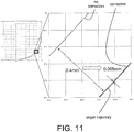
- the misalignment from the target trajectory is suppressed by performing the correction of the difference between the response delay times of the axes and the correction of the position deviation at the time of the change in the acceleration, as illustrated in Fig. 11 .
- the correction of the difference between the response delay times of the axes may be realized by a first term of the following Equation Ax, and the correction of the position deviation at the time of the change in the acceleration may be realized by a second term of the following Equation Ax.
- Xcp t X t ⁇ Rs ⁇ Rx ⁇ 1 / 2 ⁇ Rx 2 ⁇ Ax
- Equation 2 An effect of Equation 2 can be obtained by Equation 1.
- Xpp t X t ⁇ Rs + td ⁇ Xap t
- an acceleration Ax of the second term of Equation 1 a primary delay calculation of a result obtained by (d 2 x/dt 2 ) (t-(Rs-Rx)) is performed with an inverse number Rx of the position loop gain as a primary delay time constant, and a result obtained by performing the primary delay calculation with 1/(2 ⁇ speed loop gain) as the primary delay time constant is used as the acceleration Ax.
- the correction of the difference between the response delay times of the axes may be realized by a first term of the following Equation 3, and the correction of the position deviation at the time of the change in the acceleration may be realized by a second term of the following Equation 3.
- Ycp t Y t ⁇ Rs ⁇ Ry ⁇ 1 / 2 ⁇ Ry 2 ⁇ Ay
- Equation 4 An effect of Equation 4 can be obtained by Equation 3.
- Ypp t Y t ⁇ Rs + td ⁇ Yap t
- Equation 3 a primary delay calculation of a result obtained by (d 2 y/dt 2 ) (t-(Rs-Ry)) is performed with an inverse number Ry of the position loop gain as a primary delay time constant, and a result obtained by performing the primary delay calculation with 1/(2 ⁇ speed loop gain) as the primary delay time constant is used as the acceleration Ay.
- the correction of the difference between the response delay times of the axes may be realized by a first term of the following Equation 5, and the correction of the position deviation at the time of the change in the acceleration may be realized by a second term of the following Equation 5.
- Zcp t Z t ⁇ Rs ⁇ Rz ⁇ 1 / 2 ⁇ Rz 2 ⁇ Az
- Equation 6 An effect of Equation 6 can be obtained by Equation 5.
- Zpp t Z t ⁇ Rs + td ⁇ Zap t
- an acceleration Az of the second term of Equation 5 a primary delay calculation of a result obtained by (d 2 z/dt 2 ) (t-(Rs-Rz)) is performed with an inverse number Rz of the position loop gain as a primary delay time constant, and a result obtained by performing the primary delay calculation with 1/(2 ⁇ speed loop gain) as the primary delay time constant is used as the acceleration Az.
- Each of the functional modules of the control device may be realized by software using a central processing unit (CPU) or may be realized by a logic circuit (hardware) formed in an integrated circuit (IC chip) or the like.
- CPU central processing unit
- IC chip integrated circuit
- the control device includes a CPU which performs an instruction of a control program which is software realizing each function, a read only memory (ROM)) or storage device (these are referred to as “recording media") in which the control program and a variety of data are recorded to be readable by a computer (or CPU), a random access memory (RAM) which develops the control program, and so on. Additionally, the computer (or CPU) reads and executes the control program from the recording medium, thereby achieving an object of the embodiment.
- a "non-temporary tangible medium” such as a disk, a card, a semiconductor memory, a programmable logic circuit, or the like can be used as the recording medium.
- control program may also be provided to the computer via any transmission medium (communication networks, broadcast waves, or the like) which can transmit the control program.
- transmission medium communication networks, broadcast waves, or the like
- embodiment can also be realized in the form of data signals embedded in carrier waves in which the control program is embodied by electronic transmission.
- This control device is a control device which issues commands to a plurality of servo drivers corresponding to a plurality of servomotors and is characterized in that a servo driver corresponding to a standard servomotor having a maximum response delay time among the plurality of servomotors is set as a standard servo driver, and a command timing to another servo driver is delayed from a command timing to the standard servo driver by a difference between a response delay time of the standard servomotor and a response delay time of the servomotor corresponding to the another servo driver.
- the commands may be position commands based on the target trajectory.
- the response delay time of each of the servomotors may be indicated by an inverse number of a position loop gain of the corresponding servo driver.
- the position command may be issued with applying a correction of an amount proportional to acceleration at the time of a change in the acceleration of each of the servomotors.
- This control method is a control method of issuing commands to a plurality of servo drivers corresponding to a plurality of servomotors and causing the plurality of servomotors to respond and is characterized by including a first step of obtaining a response delay time of each of the servomotors, a second step of comparing the response delay times, and a third step of setting a servo driver corresponding to a standard servomotor having a maximum response delay time among the plurality of servomotors as a standard servo driver and delaying a position command to another servo driver from a position command to the standard servo driver by a difference between a response delay time of the standard servomotor and a response delay time of the servomotor corresponding to the other servo driver.
- an inverse number of a position loop gain of each of the servo drivers may be compared in the second step.
- This control program causes a processor to execute the first to third steps.
- This recording medium is a computer-readable recording medium in which the control program is recorded.
- the present invention is not limited to the above-described embodiments, and those obtained by appropriately changing the above embodiments on the basis of common general knowledge or those obtained by combining them are also included in the embodiments of the present invention.
Landscapes
- Engineering & Computer Science (AREA)
- Robotics (AREA)
- Mechanical Engineering (AREA)
- Physics & Mathematics (AREA)
- General Physics & Mathematics (AREA)
- Automation & Control Theory (AREA)
- Power Engineering (AREA)
- Human Computer Interaction (AREA)
- Manufacturing & Machinery (AREA)
- Control Of Position Or Direction (AREA)
- Numerical Control (AREA)
- Control Of Multiple Motors (AREA)
Abstract
Description
- The present invention relates to a control device, a control method, and a control program.
- Patent Literature 1 discloses a method of controlling an operation of a robot, in which a control device for controlling a motion of the robot calculates a difference between a target trajectory and an actual motion trajectory with respect to a command value for each axis as a servo delay time, sets the shortest servo delay time as a reference time, calculates a compensation torque for each axis on the basis of the servo delay time for each axis and the reference time, and controls the operation of the robot by outputting a command value reflecting the compensation torque for each axis to each servo.
- [Patent Literature 1]
Japanese Unexamined Patent Application Publication No.2009-151527 - In the above-described method, there is a problem that calculation of the compensation torque based on the servo delay time for each axis and the reference time and calculation of the command value reflecting the compensation torque are complicated.
- The present invention has been made in view of the above problem, and it is an object of the present invention to realize a control device capable of suppressing trajectory misalignment due to a deviation between response delay times of a plurality of axes (a plurality of servomotors).
- This control device is a control device which issues commands to a plurality of servo drivers corresponding to a plurality of servomotors, wherein a servo driver corresponding to a standard servomotor having a maximum response delay time among the plurality of servomotors is set as a standard servo driver, and a command timing to another servo driver is delayed from a command timing to the standard servo driver by a difference between a response delay time of the standard servomotor and a response delay time of a servomotor corresponding to the another servo driver.
- According to the control device, it is possible to suppress trajectory misalignment due to a deviation between response delay times of a plurality of servomotors.
-
-
Fig. 1 is a schematic view illustrating a configuration having a plurality of axes. -
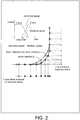
Fig. 2 is a reference diagram illustrating an example of trajectory misalignment due to a difference between response delay times of the axes. -
Fig. 3 is a reference diagram illustrating a principle of the trajectory misalignment due to the difference between response delay times of the axes. -
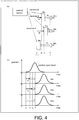
Fig. 4 is an explanatory diagram illustrating a position command of a control device according to the present invention. -
Fig. 5 is a reference diagram illustrating an example of trajectory misalignment due to a positional deviation at the time of a change in acceleration. -
Fig. 6 is an explanatory diagram illustrating a principle of suppressing the trajectory misalignment due to the positional deviation at the time of the change in the acceleration. -
Fig. 7 is an explanatory diagram illustrating a method of suppressing the trajectory misalignment due to the positional deviation at the time of the change in the acceleration. -
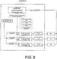
Fig. 8 is a schematic view illustrating a function module of the control device. -
Fig. 9 is a schematic view illustrating a configuration example of each servo driver according to an embodiment. -
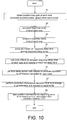
Fig. 10 is a flowchart illustrating processing steps of the control device. -
Fig. 11 is a trajectory diagram illustrating an effect of the embodiment. - An embodiment of the present invention will be described with reference to
Figs. 1 to 11 . Hereinafter, description will be made on the assumption of a synchronous group having three axes (X axis, Y axis and Z axis) as illustrated inFig. 1 , but the synchronous group of the embodiment may have a configuration having two or more axes. - In the three-axis configuration as illustrated in
Fig. 1 , for example, an X axis servo driver which receives a command from a control device controls an X axis servomotor, and a workpiece Wx moves in an X-axial direction due to the X axis servomotor (operation information of the X axis servomotor is fed back to the X axis servo driver). Also, a Y axis servo driver which receives a command from the control device controls a Y axis servomotor, and a workpiece Wy moves in a Y-axial direction due to the Y axis servomotor (operation information of the Y axis servomotor is fed back to the Y axis servo driver). Also, a Z axis servo driver which receives a command from the control device controls a Z axis servomotor, and a workpiece Wz moves in a Z-axial direction due to the Z axis servomotor (operation information of the Z axis servomotor is fed back to the Z axis servo driver). - Generally, the commands to the X axis servo driver, the Y axis servo driver and the Z axis servo driver are synchronized, but a time (response delay time) until the corresponding servomotor responds after receipt of the command varies according to the axes.
- For example, when there is almost no (small) response delay in a Y axis system and the response delay in a Z axis system is large, as illustrated in
Fig. 2 , a command speed and a feedback speed almost coincide with each other in the Y axis system, whereas the command speed and the feedback speed are temporally misaligned in the Z axis system, and thus a rise in the Z-axial direction on a corner trajectory is delayed, resulting in a trajectory located outward from a target trajectory. - That is, as illustrated in
Fig. 3(a) , when it is assumed that the response delay time of the X axis servo driver (hereinafter, servo driver SDx) is Rx, the response delay time of the Y axis servo driver (hereinafter, servo driver SDy) is Ry, the response delay time of the Z axis servo driver (hereinafter, servo driver SDz) is Rz, and position commands reach the servo driver SDx, the servo driver SDy and the servo driver SDz in synchronization with a time t, a response time of the servomotor SMx is Tx (= t+Rx), a response time of the servomotor SMy with the minimum response delay time is Ty (= t+Ry), the response time of the servomotor SMz with the maximum response delay time is Tz (= t+Rz), and the three servomotors respond at scattered times and pass through a trajectory misaligned from the target trajectory as illustrated inFig. 3(b) . - Therefore, in the embodiment, in order to suppress the trajectory misalignment due to the difference between the response delay times of the axes, as illustrated in
Fig. 4(a) , the position commands to the servo driver SDx, the servo driver SDy and the servo driver SDz are issued at staggered times. - Specifically, the servomotor SMz having the maximum response delay time is set as a standard servomotor, and in order to cause the servomotor SMx and the servomotor SMy to respond in synchronization with a response time T of the servomotor SMz, a command time tx to the servo driver SDx is delayed by dx (a difference (= Rz-Rx) between the response delay times of the standard servomotor SMz and the servomotor SMx) and a command time tx to the servo driver SDy is delayed by dy (a difference (= Rz-Ry) between the response delay times of the standard servomotor SMz and the servomotor SMy) with respect to a command time tz to the servo driver SDz (standard servo driver) which controls the servomotor SMz (standard servomotor).
- For example, when target position coordinates at a certain time are (Px, Py, Pz), the position command of Px to the servo driver SDx is delayed by dx from the position command of Pz to the servo driver SDz, and the position command of Py to the servo driver SDy is delayed by dy from the position command of Pz to the servo driver SDz. Therefore, as illustrated in
Fig. 4(b) , it is possible to obtain a trajectory close to the target trajectory. - Although a response timing between the axes is aligned by the above-described method, there is a response delay of each axis itself. Therefore, as illustrated in
Fig. 5 , when a speed command to the X axis servo driver is changed from small to large and the speed command to the Y axis servo driver is changed from large to small, the positional deviation (difference between the command position and the feedback position) of the X axis increases temporally while the positional deviation (difference between the command position and the feedback position) of the Y axis decreases temporally, and thus it may result in a trajectory located inward from the target trajectory, as illustrated inFig. 5 . - In a model in which the command speed and the feedback speed are misaligned by the response delay time as illustrated in
Fig. 6(a) , the inventor found that it is effective to correct a shaded portion with respect to the trajectory misalignment due to the positional deviation at the time of a change in acceleration (including a change in a positive direction and a change in a negative direction) as illustrated inFig. 6(b) . Specifically, a correction of the command position is performed by an amount corresponding to (1/2) × the square of the response delay time × the acceleration (predictive acceleration) which corresponds to an area of the shaded portion. - In this way, even when a feedback position of a return trajectory as shown in
Fig. 7(a) has not reached a return point, the feedback position reaches the turning point with the correction of the command position, as illustrated inFig. 7(b) . - The control device according to the embodiment includes a processor having function modules as illustrated in
Fig. 8 . The function modules of the processor include a predictive synchronization calculation unit, a command position generation unit, an X axis position correction unit, a Y axis position correction unit, a Z axis position correction unit, an X axis command unit, a Y axis command unit, and a Z axis command unit. - The predictive synchronization calculation unit reads out servo parameters from the servo driver SDx, the servo driver SDy and the servo driver SDz and calculates predictive position synchronization correction parameters including an X axis response delay time, a Y axis response delay time, a Z axis response delay time, and a standard response delay time.
- Here, the X axis response delay time (Rx in
Figs. 3 and4 ) is an inverse number of a position loop gain which is one of the servo parameters of the servo driver SDx, the Y axis response delay time (Ry inFigs. 3 and4 ) is an inverse number of a position loop gain which is one of the servo parameters of the servo driver SDy, the Z axis response delay time (Rz inFigs. 3 and4 ) is an inverse number of a position loop gain which is one of the servo parameters of the servo driver SDz, and a standard response delay time is a maximum value of Rx, Ry and Rz. - The command position generation unit generates an X axis command position, a Y axis command position, and a Z axis command position on the basis of the target trajectory, inputs the X axis command position to the X axis position correction unit, inputs the Y axis command position to the Y axis position correction unit and inputs the Z axis command position to the Z axis position correction unit.
- The X axis position correction unit performs a correction of the X axis command position (a correction relating to the difference between the response delay times of the axes and a correction relating to the position deviation generated by the change in the acceleration) on the basis of the predictive position synchronization correction parameter, and the X axis command unit issues the position command to the servo driver SDx on the basis of the corrected X axis command position.
- The Y axis position correction unit performs a correction of the Y axis command position (the correction relating to the difference between the response delay times of the axes and the correction relating to the position deviation generated by the change in the acceleration) on the basis of the predictive position synchronization correction parameter, and the Y axis command unit issues the position command to the servo driver SDy on the basis of the corrected Y axis command position.
- The Z axis position correction unit performs a correction of the Z axis command position (the correction relating to the difference between the response delay times of the axes and the correction relating to the position deviation generated by the change in the acceleration) on the basis of the predictive position synchronization correction parameter, and the Z axis command unit issues the position command to the servo driver SDz on the basis of the corrected Z axis command position.
- As illustrated in
Fig. 9 , the servo driver SDx includes an X axis position control unit which receives the position command from the control device, an X axis speed control unit which receives an output from the X axis position control unit, and an X axis current control unit (X axis torque control unit) which receives an output from the X axis speed control unit, a rotating portion of the servomotor SMx is driven by an output of the X axis current control unit, and an output of an encoder of the servomotor SMx is fed back to the X axis position control unit, the X axis speed control unit and the X axis current control unit. The X axis position control unit outputs a position loop gain to the control device, and the X axis speed control unit outputs a speed loop gain to the control device. - Further, the servo driver SDy includes a Y axis position control unit which receives the position command from the control device, a Y axis speed control unit which receives an output from the Y axis position control unit, and a Y axis current control unit (Y axis torque control unit) which receives an output from the Y axis speed control unit, a rotating portion of the servomotor SMy is driven by an output of the Y axis current control unit, and an output of an encoder of the servomotor SMy is fed back to the Y axis position control unit, the Y axis speed control unit and the Y axis current control unit. The Y axis position control unit outputs a position loop gain to the control device, and the Y axis speed control unit outputs a speed loop gain to the control device.
- Further, the servo driver SDz includes a Z axis position control unit which receives the position command from the control device, a Z axis speed control unit which receives an output from the Z axis position control unit, and a Z axis current control unit (Z axis torque control unit) which receives an output from the Z axis speed control unit, a rotating portion of the servomotor SMz is driven by an output of the Z axis current control unit, and an output of an encoder of the servomotor SMz is fed back to the Z axis position control unit, the Z axis speed control unit and the Z axis current control unit. The Z axis position control unit outputs a position loop gain to the control device, and the Z axis speed control unit outputs a speed loop gain to the control device.
- The processor of the control device performs steps S1 to S8 in
Fig. 10 by executing, for example, a control program according to the embodiment. - That is, the position loop gain of each axis (of a preset synchronization group) is acquired from the servo driver in Step S1, the response delay time of each of the axes is calculated in Step S2, the response delay times of the axes are compared with each other in Step S3, the maximum response delay time of the response delay times is calculated in Step S4, a difference between the response delay time and the maximum response delay time of each of the axes is calculated in Step S5, a delay correction with respect to the command position by the difference calculated for each of the axes is performed in Step S6, a correction of the position deviation generated by the change in the acceleration according to a result of Step S6, specifically, a correction of the position deviation generated in proportion to the acceleration, is performed in Step S7, and in Step 8, the position command is issued to the corresponding servo driver on the basis of the corrected command position obtained in Step S7.
- As described above, it can be understood that the misalignment from the target trajectory is suppressed by performing the correction of the difference between the response delay times of the axes and the correction of the position deviation at the time of the change in the acceleration, as illustrated in
Fig. 11 . - In the X axis position correction unit of
Fig. 8 or Step S7 ofFig. 10 , the correction of the difference between the response delay times of the axes may be realized by a first term of the following Equation Ax, and the correction of the position deviation at the time of the change in the acceleration may be realized by a second term of the following Equation Ax.

- X(t): Target position (target trajectory)
- Xcp(t): Command position provided to the servo driver SDx
- Rx: X axis response delay time (of which an inverse number is the position loop gain)
- Ax: X axis acceleration (predictive acceleration)
- td: Communication delay time (common among the axes)
- Rs: Standard response delay time (maximum value of Rx, Ry and Rz)
- An effect of
Equation 2 can be obtained by Equation 1.
- Xpp(t): Predictive position
- Xap(t): Actual position (feedback position) when Xcp(t) is provided
- Here, regarding an acceleration Ax of the second term of Equation 1, a primary delay calculation of a result obtained by (d2x/dt2) (t-(Rs-Rx)) is performed with an inverse number Rx of the position loop gain as a primary delay time constant, and a result obtained by performing the primary delay calculation with 1/(2π×speed loop gain) as the primary delay time constant is used as the acceleration Ax.
- Further, in the Y axis position correction unit of
Fig. 8 or Step S7 ofFig. 10 , the correction of the difference between the response delay times of the axes may be realized by a first term of the following Equation 3, and the correction of the position deviation at the time of the change in the acceleration may be realized by a second term of the following Equation 3.

- Y(t): Target position (target trajectory)
- Ycp(t): Command position provided to the servo driver SDy
- Ry: Y axis response delay time (of which an inverse number is the position loop gain)
- Ay: Y axis acceleration (predictive acceleration)
- td: Communication delay time (common among the axes)
- Rs: Standard response delay time (maximum value of Rx, Ry and Rz)
- An effect of Equation 4 can be obtained by Equation 3.

- Ypp(t): Predictive position
- Yap(t): Actual position (feedback position) when Ycp(t) is provided
- Here, regarding an acceleration Ay of the second term of Equation 3, a primary delay calculation of a result obtained by (d2y/dt2) (t-(Rs-Ry)) is performed with an inverse number Ry of the position loop gain as a primary delay time constant, and a result obtained by performing the primary delay calculation with 1/(2π× speed loop gain) as the primary delay time constant is used as the acceleration Ay.
- Further, in the Z axis position correction unit of
Fig. 8 or Step S7 ofFig. 10 , the correction of the difference between the response delay times of the axes may be realized by a first term of the following Equation 5, and the correction of the position deviation at the time of the change in the acceleration may be realized by a second term of the following Equation 5.

- Z(t): Target position (target trajectory)
- Zcp(t): Command position provided to the servo driver SDz
- Rz: Z axis response delay time (of which an inverse number is the position loop gain)
- Az: Z axis acceleration (predictive acceleration)
- td: Communication delay time (common among the axes)
- Rs: Standard response delay time (maximum value of Rx, Ry and Rz)
- An effect of Equation 6 can be obtained by Equation 5.

- Zpp(t): Predictive position
- Zap(t): Actual position (feedback position) when Zcp(t) is provided
- Here, regarding an acceleration Az of the second term of Equation 5, a primary delay calculation of a result obtained by (d2z/dt2) (t-(Rs-Rz)) is performed with an inverse number Rz of the position loop gain as a primary delay time constant, and a result obtained by performing the primary delay calculation with 1/(2π×speed loop gain) as the primary delay time constant is used as the acceleration Az.
- Each of the functional modules of the control device may be realized by software using a central processing unit (CPU) or may be realized by a logic circuit (hardware) formed in an integrated circuit (IC chip) or the like.
- In the former case, the control device includes a CPU which performs an instruction of a control program which is software realizing each function, a read only memory (ROM)) or storage device (these are referred to as "recording media") in which the control program and a variety of data are recorded to be readable by a computer (or CPU), a random access memory (RAM) which develops the control program, and so on. Additionally, the computer (or CPU) reads and executes the control program from the recording medium, thereby achieving an object of the embodiment. A "non-temporary tangible medium" such as a disk, a card, a semiconductor memory, a programmable logic circuit, or the like can be used as the recording medium. Furthermore, the control program may also be provided to the computer via any transmission medium (communication networks, broadcast waves, or the like) which can transmit the control program. In addition, the embodiment can also be realized in the form of data signals embedded in carrier waves in which the control program is embodied by electronic transmission.
- This control device is a control device which issues commands to a plurality of servo drivers corresponding to a plurality of servomotors and is characterized in that a servo driver corresponding to a standard servomotor having a maximum response delay time among the plurality of servomotors is set as a standard servo driver, and a command timing to another servo driver is delayed from a command timing to the standard servo driver by a difference between a response delay time of the standard servomotor and a response delay time of the servomotor corresponding to the another servo driver.
- According to the above-described configuration, since the response timings of the plurality of servomotors are aligned, it is possible to suppress the trajectory misalignment due to a deviation in the response delay time among the plurality of axes (the plurality of servomotors).
- In this control device, the commands may be position commands based on the target trajectory.
- In this control device, the response delay time of each of the servomotors may be indicated by an inverse number of a position loop gain of the corresponding servo driver.
- In this control device, the position command may be issued with applying a correction of an amount proportional to acceleration at the time of a change in the acceleration of each of the servomotors.
- According to the above-described configuration, it is possible to suppress the trajectory misalignment due to the positional deviation at the time of the change in the acceleration.
- This control method is a control method of issuing commands to a plurality of servo drivers corresponding to a plurality of servomotors and causing the plurality of servomotors to respond and is characterized by including a first step of obtaining a response delay time of each of the servomotors, a second step of comparing the response delay times, and a third step of setting a servo driver corresponding to a standard servomotor having a maximum response delay time among the plurality of servomotors as a standard servo driver and delaying a position command to another servo driver from a position command to the standard servo driver by a difference between a response delay time of the standard servomotor and a response delay time of the servomotor corresponding to the other servo driver.
- According to the above-described method, since the response timings of the plurality of servomotors are aligned, it is possible to suppress the trajectory misalignment due to the deviation in the response delay time among the plural axes (plural servo motors).
- In this control method, an inverse number of a position loop gain of each of the servo drivers may be compared in the second step.
- This control program causes a processor to execute the first to third steps.
- This recording medium is a computer-readable recording medium in which the control program is recorded.
- The present invention is not limited to the above-described embodiments, and those obtained by appropriately changing the above embodiments on the basis of common general knowledge or those obtained by combining them are also included in the embodiments of the present invention.
-
- SDx Servo driver (X axis)
- SDy Servo driver (Y axis)
- SDz Servo driver (Z axis)
- SMx Servomotor (X axis)
- SMy Servomotor (Y axis)
- SMz Servomotor (Z axis)
- Rx Response delay time (X axis)
- Ry Response delay time (Y axis)
- Rz Response delay time (Z axis)
Claims (8)
- A control device which issues commands to a plurality of servo drivers corresponding to a plurality of servomotors,
wherein a servo driver corresponding to a standard servomotor having a maximum response delay time among the plurality of servomotors is set as a standard servo driver, and a command timing to another servo driver is delayed from a command timing to the standard servo driver by a difference between a response delay time of the standard servomotor and a response delay time of a servomotor corresponding to the another servo driver. - The control device according to claim 1, wherein the commands are position commands based on a target trajectory.
- The control device according to claim 2, wherein the response delay time of each servomotor is indicated by an inverse number of a position loop gain of a corresponding servo driver.
- The control device according to claim 2, wherein the position commands are issued with applying a correction of an amount proportional to acceleration at the time of a change in the acceleration of each servomotor.
- A control method of issuing commands to a plurality of servo drivers corresponding to a plurality of servomotors and causing the plurality of servomotors to respond, the control method comprising:a first step of obtaining a response delay time of each servomotor,a second step of comparing the response delay times, anda third step of setting a servo driver corresponding to a standard servomotor having a maximum response delay time among the plurality of servomotors as a standard servo driver and delaying a position command to another servo driver from a position command to the standard servo driver by a difference between a response delay time of the standard servomotor and a response delay time of a servomotor corresponding to the another servo driver.
- The control method according to claim 5, wherein, in the second step, an inverse number of a position loop gain read from each servo driver is compared.
- A control program which causes a processor to execute the first to third steps disclosed in claim 5 or 6.
- A recoding medium which is a computer-readable recording medium in which the control program disclosed in claim 7 is recorded.
Applications Claiming Priority (2)
| Application Number | Priority Date | Filing Date | Title |
|---|---|---|---|
| JP2015234142A JP6551199B2 (en) | 2015-11-30 | 2015-11-30 | Control device, control method, control program |
| PCT/JP2016/082293 WO2017094423A1 (en) | 2015-11-30 | 2016-10-31 | Control device, control method, and control program |
Publications (3)
| Publication Number | Publication Date |
|---|---|
| EP3385813A1 true EP3385813A1 (en) | 2018-10-10 |
| EP3385813A4 EP3385813A4 (en) | 2019-11-20 |
| EP3385813B1 EP3385813B1 (en) | 2024-11-27 |
Family
ID=58797119
Family Applications (1)
| Application Number | Title | Priority Date | Filing Date |
|---|---|---|---|
| EP16870363.5A Active EP3385813B1 (en) | 2015-11-30 | 2016-10-31 | Control device, control method, control program and recording medium |
Country Status (5)
| Country | Link |
|---|---|
| US (1) | US10118294B2 (en) |
| EP (1) | EP3385813B1 (en) |
| JP (1) | JP6551199B2 (en) |
| CN (1) | CN107924198B (en) |
| WO (1) | WO2017094423A1 (en) |
Families Citing this family (10)
| Publication number | Priority date | Publication date | Assignee | Title |
|---|---|---|---|---|
| TWI674743B (en) * | 2018-09-17 | 2019-10-11 | 士林電機廠股份有限公司 | The servo drives control system for the synchronized mechanism |
| JP6845197B2 (en) * | 2018-09-27 | 2021-03-17 | ファナック株式会社 | Servo control device |
| CN109361330A (en) * | 2018-10-18 | 2019-02-19 | 东莞市旭展自动化科技有限公司 | A kind of servo motor synchronisation control means based on bus |
| JP6849713B2 (en) * | 2019-02-13 | 2021-03-24 | オムロン株式会社 | Control devices, control methods, control programs, and recording media |
| CN111421543B (en) * | 2020-04-07 | 2021-09-28 | 慧灵科技(深圳)有限公司 | Control method, device and system of mechanical arm and storage medium |
| JP7040567B2 (en) * | 2020-08-18 | 2022-03-23 | オムロン株式会社 | Control device, control method of control device, information processing program, and recording medium |
| JP7052840B2 (en) * | 2020-08-18 | 2022-04-12 | オムロン株式会社 | Positioning device, control method of position specifying device, information processing program, and recording medium |
| CN115642856A (en) * | 2022-10-28 | 2023-01-24 | 闻泰通讯股份有限公司 | Motor control method, device, electronic device and storage medium |
| CN116501020B (en) * | 2023-05-10 | 2023-11-03 | 上海铼钠克数控科技有限公司 | Servo matching detection method, apparatus, device and readable storage medium |
| WO2025243450A1 (en) * | 2024-05-23 | 2025-11-27 | 日産自動車株式会社 | Ecu control system and ecu control method |
Family Cites Families (11)
| Publication number | Priority date | Publication date | Assignee | Title |
|---|---|---|---|---|
| JPS5652408A (en) * | 1979-09-28 | 1981-05-11 | Shin Meiwa Ind Co Ltd | Automatic position control unit |
| JPS5676394A (en) * | 1979-11-16 | 1981-06-23 | Fujikoshi Kk | Positioning device for industrial robot |
| US4409650A (en) * | 1981-03-04 | 1983-10-11 | Shin Meiwa Industry Co., Ltd. | Automatic position controlling apparatus |
| JPS59194206A (en) * | 1983-04-20 | 1984-11-05 | Fanuc Ltd | Control system for delay error correction of servo system in numerical control |
| JPS6123213A (en) | 1984-07-10 | 1986-01-31 | Kobe Steel Ltd | Robot controller |
| JPH0420103A (en) | 1990-05-15 | 1992-01-23 | Matsushita Electric Works Ltd | Planar antenna |
| JPH0420103U (en) * | 1990-06-12 | 1992-02-20 | ||
| JPH0916229A (en) * | 1995-06-29 | 1997-01-17 | Shin Meiwa Ind Co Ltd | Industrial robot |
| JP4992702B2 (en) | 2007-12-20 | 2012-08-08 | 株式会社デンソーウェーブ | Robot motion control apparatus and motion control method thereof |
| JP5366840B2 (en) * | 2010-01-14 | 2013-12-11 | 三菱電機株式会社 | Trajectory control device |
| CN104751864A (en) * | 2015-03-09 | 2015-07-01 | 广东欧珀移动通信有限公司 | A control method for multiplayer equipment, related equipment and system |
-
2015
- 2015-11-30 JP JP2015234142A patent/JP6551199B2/en active Active
-
2016
- 2016-10-31 WO PCT/JP2016/082293 patent/WO2017094423A1/en not_active Ceased
- 2016-10-31 EP EP16870363.5A patent/EP3385813B1/en active Active
- 2016-10-31 CN CN201680046364.0A patent/CN107924198B/en active Active
- 2016-10-31 US US15/750,832 patent/US10118294B2/en active Active
Also Published As
| Publication number | Publication date |
|---|---|
| WO2017094423A1 (en) | 2017-06-08 |
| JP6551199B2 (en) | 2019-07-31 |
| JP2017102616A (en) | 2017-06-08 |
| CN107924198A (en) | 2018-04-17 |
| US20180229365A1 (en) | 2018-08-16 |
| EP3385813A4 (en) | 2019-11-20 |
| EP3385813B1 (en) | 2024-11-27 |
| CN107924198B (en) | 2021-05-14 |
| US10118294B2 (en) | 2018-11-06 |
Similar Documents
| Publication | Publication Date | Title |
|---|---|---|
| US10118294B2 (en) | Control device, control method and non-transitory recording medium | |
| US20220362929A1 (en) | Decoupling control method for humanoid robot, humanoid robot and computer-readable storage medium | |
| US12240119B2 (en) | Motion control method, robot, and computer-readable storage medium | |
| CN115157249A (en) | Dynamic target tracking method and device and robot | |
| US8432120B2 (en) | Tool path display apparatus with deceleration factor identification means for machine tool | |
| CN104204977B (en) | trajectory control device | |
| EP3171235B1 (en) | Control device, control method, information processing program, and recording medium | |
| CN108356823A (en) | Control system with learning control function and control method | |
| US10556341B2 (en) | Trajectory determination method for non-productive movements | |
| KR20150103561A (en) | EtherCAT CONTROL DEVICE AND FACTORY AUTOMATION SYSTEM HAVING THE SAME | |
| EP3912767A1 (en) | Robot control device, robot control method, and robot control program | |
| CN108628188A (en) | Control system, controller and control method | |
| Tsai et al. | Backstepping aggregated sliding-mode motion control for automatic 3D overhead cranes | |
| JP6627999B2 (en) | Control device, control method, control program | |
| CN107465367A (en) | A kind of method and device of motor control | |
| US10101726B2 (en) | Autonomous control system | |
| US10507579B2 (en) | Control system to which control CPU is addable | |
| JP6849713B2 (en) | Control devices, control methods, control programs, and recording media | |
| CN119512175A (en) | Underwater vehicle formation control method and system based on LOS constraints | |
| US9905264B2 (en) | Servo control system having function of switching learning memory | |
| JP6258480B2 (en) | Image processing apparatus and positioning system | |
| JP6607097B2 (en) | Control device, control method, information processing program, and recording medium | |
| US20240045058A1 (en) | Signal processing apparatus, signal processing method, and program | |
| JPWO2018154745A1 (en) | Electronic cam pattern generation method and electronic cam pattern generation device | |
| JP2006227719A (en) | Motion control system |
Legal Events
| Date | Code | Title | Description |
|---|---|---|---|
| STAA | Information on the status of an ep patent application or granted ep patent |
Free format text: STATUS: THE INTERNATIONAL PUBLICATION HAS BEEN MADE |
|
| PUAI | Public reference made under article 153(3) epc to a published international application that has entered the european phase |
Free format text: ORIGINAL CODE: 0009012 |
|
| STAA | Information on the status of an ep patent application or granted ep patent |
Free format text: STATUS: REQUEST FOR EXAMINATION WAS MADE |
|
| 17P | Request for examination filed |
Effective date: 20180212 |
|
| AK | Designated contracting states |
Kind code of ref document: A1 Designated state(s): AL AT BE BG CH CY CZ DE DK EE ES FI FR GB GR HR HU IE IS IT LI LT LU LV MC MK MT NL NO PL PT RO RS SE SI SK SM TR |
|
| AX | Request for extension of the european patent |
Extension state: BA ME |
|
| DAV | Request for validation of the european patent (deleted) | ||
| DAX | Request for extension of the european patent (deleted) | ||
| A4 | Supplementary search report drawn up and despatched |
Effective date: 20191017 |
|
| RIC1 | Information provided on ipc code assigned before grant |
Ipc: G05D 3/12 20060101ALI20191011BHEP Ipc: G05B 19/4155 20060101AFI20191011BHEP Ipc: B25J 9/02 20060101ALI20191011BHEP Ipc: H02P 5/50 20160101ALI20191011BHEP |
|
| STAA | Information on the status of an ep patent application or granted ep patent |
Free format text: STATUS: EXAMINATION IS IN PROGRESS |
|
| 17Q | First examination report despatched |
Effective date: 20211202 |
|
| GRAP | Despatch of communication of intention to grant a patent |
Free format text: ORIGINAL CODE: EPIDOSNIGR1 |
|
| STAA | Information on the status of an ep patent application or granted ep patent |
Free format text: STATUS: GRANT OF PATENT IS INTENDED |
|
| INTG | Intention to grant announced |
Effective date: 20240529 |
|
| GRAS | Grant fee paid |
Free format text: ORIGINAL CODE: EPIDOSNIGR3 |
|
| GRAA | (expected) grant |
Free format text: ORIGINAL CODE: 0009210 |
|
| STAA | Information on the status of an ep patent application or granted ep patent |
Free format text: STATUS: THE PATENT HAS BEEN GRANTED |
|
| AK | Designated contracting states |
Kind code of ref document: B1 Designated state(s): AL AT BE BG CH CY CZ DE DK EE ES FI FR GB GR HR HU IE IS IT LI LT LU LV MC MK MT NL NO PL PT RO RS SE SI SK SM TR |
|
| REG | Reference to a national code |
Ref country code: GB Ref legal event code: FG4D |
|
| REG | Reference to a national code |
Ref country code: CH Ref legal event code: EP |
|
| REG | Reference to a national code |
Ref country code: DE Ref legal event code: R096 Ref document number: 602016090440 Country of ref document: DE |
|
| REG | Reference to a national code |
Ref country code: IE Ref legal event code: FG4D |
|
| REG | Reference to a national code |
Ref country code: LT Ref legal event code: MG9D |
|
| REG | Reference to a national code |
Ref country code: NL Ref legal event code: MP Effective date: 20241127 |
|
| PG25 | Lapsed in a contracting state [announced via postgrant information from national office to epo] |
Ref country code: HR Free format text: LAPSE BECAUSE OF FAILURE TO SUBMIT A TRANSLATION OF THE DESCRIPTION OR TO PAY THE FEE WITHIN THE PRESCRIBED TIME-LIMIT Effective date: 20241127 Ref country code: PT Free format text: LAPSE BECAUSE OF FAILURE TO SUBMIT A TRANSLATION OF THE DESCRIPTION OR TO PAY THE FEE WITHIN THE PRESCRIBED TIME-LIMIT Effective date: 20250327 Ref country code: IS Free format text: LAPSE BECAUSE OF FAILURE TO SUBMIT A TRANSLATION OF THE DESCRIPTION OR TO PAY THE FEE WITHIN THE PRESCRIBED TIME-LIMIT Effective date: 20250327 |
|
| PG25 | Lapsed in a contracting state [announced via postgrant information from national office to epo] |
Ref country code: FI Free format text: LAPSE BECAUSE OF FAILURE TO SUBMIT A TRANSLATION OF THE DESCRIPTION OR TO PAY THE FEE WITHIN THE PRESCRIBED TIME-LIMIT Effective date: 20241127 Ref country code: NL Free format text: LAPSE BECAUSE OF FAILURE TO SUBMIT A TRANSLATION OF THE DESCRIPTION OR TO PAY THE FEE WITHIN THE PRESCRIBED TIME-LIMIT Effective date: 20241127 |
|
| REG | Reference to a national code |
Ref country code: AT Ref legal event code: MK05 Ref document number: 1746270 Country of ref document: AT Kind code of ref document: T Effective date: 20241127 |
|
| PG25 | Lapsed in a contracting state [announced via postgrant information from national office to epo] |
Ref country code: BG Free format text: LAPSE BECAUSE OF FAILURE TO SUBMIT A TRANSLATION OF THE DESCRIPTION OR TO PAY THE FEE WITHIN THE PRESCRIBED TIME-LIMIT Effective date: 20241127 |
|
| PG25 | Lapsed in a contracting state [announced via postgrant information from national office to epo] |
Ref country code: ES Free format text: LAPSE BECAUSE OF FAILURE TO SUBMIT A TRANSLATION OF THE DESCRIPTION OR TO PAY THE FEE WITHIN THE PRESCRIBED TIME-LIMIT Effective date: 20241127 |
|
| PG25 | Lapsed in a contracting state [announced via postgrant information from national office to epo] |
Ref country code: NO Free format text: LAPSE BECAUSE OF FAILURE TO SUBMIT A TRANSLATION OF THE DESCRIPTION OR TO PAY THE FEE WITHIN THE PRESCRIBED TIME-LIMIT Effective date: 20250227 |
|
| PG25 | Lapsed in a contracting state [announced via postgrant information from national office to epo] |
Ref country code: LV Free format text: LAPSE BECAUSE OF FAILURE TO SUBMIT A TRANSLATION OF THE DESCRIPTION OR TO PAY THE FEE WITHIN THE PRESCRIBED TIME-LIMIT Effective date: 20241127 Ref country code: AT Free format text: LAPSE BECAUSE OF FAILURE TO SUBMIT A TRANSLATION OF THE DESCRIPTION OR TO PAY THE FEE WITHIN THE PRESCRIBED TIME-LIMIT Effective date: 20241127 Ref country code: GR Free format text: LAPSE BECAUSE OF FAILURE TO SUBMIT A TRANSLATION OF THE DESCRIPTION OR TO PAY THE FEE WITHIN THE PRESCRIBED TIME-LIMIT Effective date: 20250228 |
|
| PG25 | Lapsed in a contracting state [announced via postgrant information from national office to epo] |
Ref country code: PL Free format text: LAPSE BECAUSE OF FAILURE TO SUBMIT A TRANSLATION OF THE DESCRIPTION OR TO PAY THE FEE WITHIN THE PRESCRIBED TIME-LIMIT Effective date: 20241127 |
|
| PG25 | Lapsed in a contracting state [announced via postgrant information from national office to epo] |
Ref country code: RS Free format text: LAPSE BECAUSE OF FAILURE TO SUBMIT A TRANSLATION OF THE DESCRIPTION OR TO PAY THE FEE WITHIN THE PRESCRIBED TIME-LIMIT Effective date: 20250227 |
|
| PG25 | Lapsed in a contracting state [announced via postgrant information from national office to epo] |
Ref country code: SM Free format text: LAPSE BECAUSE OF FAILURE TO SUBMIT A TRANSLATION OF THE DESCRIPTION OR TO PAY THE FEE WITHIN THE PRESCRIBED TIME-LIMIT Effective date: 20241127 |
|
| PG25 | Lapsed in a contracting state [announced via postgrant information from national office to epo] |
Ref country code: DK Free format text: LAPSE BECAUSE OF FAILURE TO SUBMIT A TRANSLATION OF THE DESCRIPTION OR TO PAY THE FEE WITHIN THE PRESCRIBED TIME-LIMIT Effective date: 20241127 |
|
| PG25 | Lapsed in a contracting state [announced via postgrant information from national office to epo] |
Ref country code: EE Free format text: LAPSE BECAUSE OF FAILURE TO SUBMIT A TRANSLATION OF THE DESCRIPTION OR TO PAY THE FEE WITHIN THE PRESCRIBED TIME-LIMIT Effective date: 20241127 |
|
| PG25 | Lapsed in a contracting state [announced via postgrant information from national office to epo] |
Ref country code: RO Free format text: LAPSE BECAUSE OF FAILURE TO SUBMIT A TRANSLATION OF THE DESCRIPTION OR TO PAY THE FEE WITHIN THE PRESCRIBED TIME-LIMIT Effective date: 20241127 |
|
| PG25 | Lapsed in a contracting state [announced via postgrant information from national office to epo] |
Ref country code: SK Free format text: LAPSE BECAUSE OF FAILURE TO SUBMIT A TRANSLATION OF THE DESCRIPTION OR TO PAY THE FEE WITHIN THE PRESCRIBED TIME-LIMIT Effective date: 20241127 |
|
| PG25 | Lapsed in a contracting state [announced via postgrant information from national office to epo] |
Ref country code: CZ Free format text: LAPSE BECAUSE OF FAILURE TO SUBMIT A TRANSLATION OF THE DESCRIPTION OR TO PAY THE FEE WITHIN THE PRESCRIBED TIME-LIMIT Effective date: 20241127 |
|
| PG25 | Lapsed in a contracting state [announced via postgrant information from national office to epo] |
Ref country code: IT Free format text: LAPSE BECAUSE OF FAILURE TO SUBMIT A TRANSLATION OF THE DESCRIPTION OR TO PAY THE FEE WITHIN THE PRESCRIBED TIME-LIMIT Effective date: 20241127 |
|
| REG | Reference to a national code |
Ref country code: DE Ref legal event code: R097 Ref document number: 602016090440 Country of ref document: DE |
|
| PG25 | Lapsed in a contracting state [announced via postgrant information from national office to epo] |
Ref country code: SE Free format text: LAPSE BECAUSE OF FAILURE TO SUBMIT A TRANSLATION OF THE DESCRIPTION OR TO PAY THE FEE WITHIN THE PRESCRIBED TIME-LIMIT Effective date: 20241127 |
|
| PLBE | No opposition filed within time limit |
Free format text: ORIGINAL CODE: 0009261 |
|
| STAA | Information on the status of an ep patent application or granted ep patent |
Free format text: STATUS: NO OPPOSITION FILED WITHIN TIME LIMIT |
|
| REG | Reference to a national code |
Ref country code: CH Ref legal event code: L10 Free format text: ST27 STATUS EVENT CODE: U-0-0-L10-L00 (AS PROVIDED BY THE NATIONAL OFFICE) Effective date: 20251008 |
|
| 26N | No opposition filed |
Effective date: 20250828 |
|
| PGFP | Annual fee paid to national office [announced via postgrant information from national office to epo] |
Ref country code: DE Payment date: 20251029 Year of fee payment: 10 |
|
| REG | Reference to a national code |
Ref country code: CH Ref legal event code: H13 Free format text: ST27 STATUS EVENT CODE: U-0-0-H10-H13 (AS PROVIDED BY THE NATIONAL OFFICE) Effective date: 20260527 |
|
| PG25 | Lapsed in a contracting state [announced via postgrant information from national office to epo] |
Ref country code: LU Free format text: LAPSE BECAUSE OF NON-PAYMENT OF DUE FEES Effective date: 20251031 |
|
| REG | Reference to a national code |
Ref country code: BE Ref legal event code: MM Effective date: 20251031 |
|
| GBPC | Gb: european patent ceased through non-payment of renewal fee |
Effective date: 20251031 |
|
| PG25 | Lapsed in a contracting state [announced via postgrant information from national office to epo] |
Ref country code: LT Free format text: LAPSE BECAUSE OF FAILURE TO SUBMIT A TRANSLATION OF THE DESCRIPTION OR TO PAY THE FEE WITHIN THE PRESCRIBED TIME-LIMIT Effective date: 20241127 |
|
| PG25 | Lapsed in a contracting state [announced via postgrant information from national office to epo] |
Ref country code: MC Free format text: LAPSE BECAUSE OF FAILURE TO SUBMIT A TRANSLATION OF THE DESCRIPTION OR TO PAY THE FEE WITHIN THE PRESCRIBED TIME-LIMIT Effective date: 20241127 |
|
| PG25 | Lapsed in a contracting state [announced via postgrant information from national office to epo] |
Ref country code: GB Free format text: LAPSE BECAUSE OF NON-PAYMENT OF DUE FEES Effective date: 20251031 |
|
| PG25 | Lapsed in a contracting state [announced via postgrant information from national office to epo] |
Ref country code: BE Free format text: LAPSE BECAUSE OF NON-PAYMENT OF DUE FEES Effective date: 20251031 Ref country code: CH Free format text: LAPSE BECAUSE OF NON-PAYMENT OF DUE FEES Effective date: 20251031 |
|
| PG25 | Lapsed in a contracting state [announced via postgrant information from national office to epo] |
Ref country code: FR Free format text: LAPSE BECAUSE OF NON-PAYMENT OF DUE FEES Effective date: 20251031 |