EP3385732A1 - Short-circuit pinpointing device - Google Patents
Short-circuit pinpointing device Download PDFInfo
- Publication number
- EP3385732A1 EP3385732A1 EP18158123.2A EP18158123A EP3385732A1 EP 3385732 A1 EP3385732 A1 EP 3385732A1 EP 18158123 A EP18158123 A EP 18158123A EP 3385732 A1 EP3385732 A1 EP 3385732A1
- Authority
- EP
- European Patent Office
- Prior art keywords
- terminal
- pump
- value
- sensor
- test
- Prior art date
- Legal status (The legal status is an assumption and is not a legal conclusion. Google has not performed a legal analysis and makes no representation as to the accuracy of the status listed.)
- Granted
Links
Images





Classifications
-
- G—PHYSICS
- G01—MEASURING; TESTING
- G01R—MEASURING ELECTRIC VARIABLES; MEASURING MAGNETIC VARIABLES
- G01R31/00—Arrangements for testing electric properties; Arrangements for locating electric faults; Arrangements for electrical testing characterised by what is being tested not provided for elsewhere
- G01R31/50—Testing of electric apparatus, lines, cables or components for short-circuits, continuity, leakage current or incorrect line connections
- G01R31/52—Testing for short-circuits, leakage current or ground faults
-
- F—MECHANICAL ENGINEERING; LIGHTING; HEATING; WEAPONS; BLASTING
- F02—COMBUSTION ENGINES; HOT-GAS OR COMBUSTION-PRODUCT ENGINE PLANTS
- F02D—CONTROLLING COMBUSTION ENGINES
- F02D41/00—Electrical control of supply of combustible mixture or its constituents
- F02D41/02—Circuit arrangements for generating control signals
- F02D41/14—Introducing closed-loop corrections
- F02D41/1438—Introducing closed-loop corrections using means for determining characteristics of the combustion gases; Sensors therefor
- F02D41/1444—Introducing closed-loop corrections using means for determining characteristics of the combustion gases; Sensors therefor characterised by the characteristics of the combustion gases
- F02D41/1454—Introducing closed-loop corrections using means for determining characteristics of the combustion gases; Sensors therefor characterised by the characteristics of the combustion gases the characteristics being an oxygen content or concentration or the air-fuel ratio
- F02D41/1456—Introducing closed-loop corrections using means for determining characteristics of the combustion gases; Sensors therefor characterised by the characteristics of the combustion gases the characteristics being an oxygen content or concentration or the air-fuel ratio with sensor output signal being linear or quasi-linear with the concentration of oxygen
-
- F—MECHANICAL ENGINEERING; LIGHTING; HEATING; WEAPONS; BLASTING
- F02—COMBUSTION ENGINES; HOT-GAS OR COMBUSTION-PRODUCT ENGINE PLANTS
- F02D—CONTROLLING COMBUSTION ENGINES
- F02D41/00—Electrical control of supply of combustible mixture or its constituents
- F02D41/02—Circuit arrangements for generating control signals
- F02D41/14—Introducing closed-loop corrections
- F02D41/1438—Introducing closed-loop corrections using means for determining characteristics of the combustion gases; Sensors therefor
- F02D41/1493—Details
- F02D41/1495—Detection of abnormalities in the air/fuel ratio feedback system
-
- F—MECHANICAL ENGINEERING; LIGHTING; HEATING; WEAPONS; BLASTING
- F02—COMBUSTION ENGINES; HOT-GAS OR COMBUSTION-PRODUCT ENGINE PLANTS
- F02D—CONTROLLING COMBUSTION ENGINES
- F02D41/00—Electrical control of supply of combustible mixture or its constituents
- F02D41/22—Safety or indicating devices for abnormal conditions
- F02D41/222—Safety or indicating devices for abnormal conditions relating to the failure of sensors or parameter detection devices
-
- G—PHYSICS
- G01—MEASURING; TESTING
- G01R—MEASURING ELECTRIC VARIABLES; MEASURING MAGNETIC VARIABLES
- G01R1/00—Details of instruments or arrangements of the types included in groups G01R5/00 - G01R13/00 and G01R31/00
- G01R1/20—Modifications of basic electric elements for use in electric measuring instruments; Structural combinations of such elements with such instruments
- G01R1/203—Resistors used for electric measuring, e.g. decade resistors standards, resistors for comparators, series resistors, shunts
-
- G—PHYSICS
- G01—MEASURING; TESTING
- G01R—MEASURING ELECTRIC VARIABLES; MEASURING MAGNETIC VARIABLES
- G01R17/00—Measuring arrangements involving comparison with a reference value, e.g. bridge
- G01R17/02—Arrangements in which the value to be measured is automatically compared with a reference value
-
- G—PHYSICS
- G01—MEASURING; TESTING
- G01R—MEASURING ELECTRIC VARIABLES; MEASURING MAGNETIC VARIABLES
- G01R31/00—Arrangements for testing electric properties; Arrangements for locating electric faults; Arrangements for electrical testing characterised by what is being tested not provided for elsewhere
- G01R31/08—Locating faults in cables, transmission lines, or networks
-
- F—MECHANICAL ENGINEERING; LIGHTING; HEATING; WEAPONS; BLASTING
- F02—COMBUSTION ENGINES; HOT-GAS OR COMBUSTION-PRODUCT ENGINE PLANTS
- F02D—CONTROLLING COMBUSTION ENGINES
- F02D41/00—Electrical control of supply of combustible mixture or its constituents
- F02D41/20—Output circuits, e.g. for controlling currents in command coils
- F02D2041/2086—Output circuits, e.g. for controlling currents in command coils with means for detecting circuit failures
- F02D2041/2093—Output circuits, e.g. for controlling currents in command coils with means for detecting circuit failures detecting short circuits
-
- G—PHYSICS
- G01—MEASURING; TESTING
- G01R—MEASURING ELECTRIC VARIABLES; MEASURING MAGNETIC VARIABLES
- G01R31/00—Arrangements for testing electric properties; Arrangements for locating electric faults; Arrangements for electrical testing characterised by what is being tested not provided for elsewhere
- G01R31/005—Testing of electric installations on transport means
- G01R31/006—Testing of electric installations on transport means on road vehicles, e.g. automobiles or trucks
-
- Y—GENERAL TAGGING OF NEW TECHNOLOGICAL DEVELOPMENTS; GENERAL TAGGING OF CROSS-SECTIONAL TECHNOLOGIES SPANNING OVER SEVERAL SECTIONS OF THE IPC; TECHNICAL SUBJECTS COVERED BY FORMER USPC CROSS-REFERENCE ART COLLECTIONS [XRACs] AND DIGESTS
- Y02—TECHNOLOGIES OR APPLICATIONS FOR MITIGATION OR ADAPTATION AGAINST CLIMATE CHANGE
- Y02T—CLIMATE CHANGE MITIGATION TECHNOLOGIES RELATED TO TRANSPORTATION
- Y02T10/00—Road transport of goods or passengers
- Y02T10/10—Internal combustion engine [ICE] based vehicles
- Y02T10/40—Engine management systems
Definitions
- This disclosure generally relates to a short-circuit pinpointing device, and more particularly relates to a short-circuit pinpointing device for testing a wide-range air-fuel sensor.
- a wide-range air-fuel sensor typically has several electrical wires that may become short-circuited to the battery or ground. Difficulty in determining which sensor wire is short-circuited may be caused by the internal cell bias voltage from the reference and pump cells, battery and ground voltage fluctuations, and large common-mode signals. Additionally, it is advantageous to be able to pinpoint a short-circuit while the sensor is at operating temperature, of which the prior art is incapable.
- a short-circuit pinpointing device for testing a wide-range air/fuel sensor.
- the short-circuit pinpointing device includes a current-sink and a controller.
- the current-sink is selectively connectable to one or more of sensor-terminals of the wide-range air/fuel sensor that include a reference-terminal, a pump-terminal, a return-terminal, and a tag-terminal.
- the controller is in communication with the current-sink and the sensor-terminals.
- the controller controls the connection of the current-sink to the one or more sensor-terminals.
- the controller also determines one or more status-values based on signals present at the sensor-terminals.
- the controller also determines a sensor-status of the wide-range air/fuel sensor based on the connection of the current-sink and the one or more status-values.
- the short-circuit pinpointing device comprises a current-sink that is selectively connectable to one or more of sensor-terminals of a wide-range air/fuel sensor that include a reference-terminal, a pump-terminal, a return-terminal, and a tag-terminal and a controller in communication with the current-sink and the sensor-terminals, wherein the controller controls a connection of the current-sink to the one or more sensor-terminals, determines one or more status-values based on signals present at the sensor-terminals, and determines a sensor-status of the wide-range air/fuel sensor based on the connection of the current-sink and the one or more status-values.
- the controller determines a first-value based on a difference between signals at the reference-terminal and the return-terminal while the current-sink is disconnected. Moreover the controller determines a second-value based on the difference between signals at the reference-terminal and the return-terminal while the current-sink is connected to the reference-terminal. The controller determines a reference-error based on the difference between the second-value and the first-value, and determines that a short-circuit is present on the reference-terminal when a reference-threshold is greater than the reference-error.
- the short-circuit pinpointing device includes three test-resistors that are each selectively connectable between two of the sensor-terminals, wherein the controller controls the connection of the test-resistor between the two sensor-terminals.
- a first-test-resistor is connected between the reference-terminal and the return-terminal
- a second-test-resistor is connected between the return-terminal and the pump-terminal
- a third-test-resistor is connected between the pump-terminal and the tag-terminal.
- the controller determines a third-value based on a difference between signals at the pump-terminal and the return-terminal while the current-sink is disconnected.
- the controller determines a fourth-value based on the difference between signals at the pump-terminal and the return-terminal while the current-sink is connected to the pump-terminal.
- the controller determines a pump-error based on the difference between the fourth-value and the third-value, and determines that a short-circuit is present on the pump-terminal when a pump-threshold is greater than the pump-error.
- the short-circuit pinpointing device includes three test-resistors that are selectively connectable between two of the sensor-terminals, wherein the controller controls the connection of the test-resistor between the two sensor-terminals.
- a first-test-resistor is not connected between the reference-terminal and the return-terminal, a second-test-resistor is connected between the return-terminal and the pump-terminal, and a third-test-resistor is connected between the pump-terminal and the tag-terminal. Furthermore the controller determines a fifth-value based on a difference between signals at the tag-terminal and the pump-terminal while the current-sink is disconnected.
- the controller determines a sixth-value based on the difference between signals at the tag-terminal and the pump-terminal while the current-sink is connected to the tag-terminal determines a tag-error based on the difference between the sixth-value and the fifth-value, and determines that a short-circuit is present on the tag-terminal when a tag-threshold is greater than the tag-error.
- the short-circuit pinpointing device includes three test-resistors that are selectively connectable between two of the sensor-terminals, wherein the controller controls the connection of the test-resistor between the two sensor-terminals. A first-test-resistor is not connected between the reference-terminal and the return-terminal.
- a second-test-resistor is connected between the return-terminal and the pump-terminal, and a third-test-resistor is connected between the pump-terminal and the tag-terminal.
- the controller determines a first-value based on a difference between signals at the reference-terminal and the return-terminal while the current-sink is disconnected, determines a second-value based on the difference between signals at the reference-terminal and the return-terminal while the current-sink is connected to the reference-terminal.
- the controller determines a reference-error based on the difference between the second-value and the first-value, and determines that a short-circuit is present on the reference-terminal when a reference-threshold is greater than the reference-error, and wherein the controller determines a third-value based on the difference between signals at the pump-terminal and the return-terminal while the current-sink is disconnected.
- the controller determines a fourth-value based on the difference between signals at the pump-terminal and the return-terminal while the current-sink is connected to the pump-terminal, determines a pump-error based on the difference between the fourth-value and the third-value, and determines that the short-circuit is present on the pump-terminal when a pump-threshold is greater than the pump-error.
- the controller determines a fifth-value based on the difference between signals at the tag-terminal and the pump-terminal while the current-sink is disconnected.
- the controller determines a sixth-value based on the difference between signals at the tag-terminal and the pump-terminal while the current-sink is connected to the tag-terminal.
- the controller determines a tag-error based on the difference between the sixth-value and the fifth-value
- the controller determines that the short-circuit is present on the tag-terminal when a tag-threshold is greater than the tag-error, and wherein the controller determines that the short-circuit is present on the return-terminal when the reference-error is greater than the reference-threshold and when the pump-error is greater than the pump-threshold and when the tag-error is greater than the tag-threshold.
- the short-circuit pinpointing device includes three test-resistors that are selectively connectable between two of the sensor-terminals, wherein the controller controls the connection of the test-resistor between the two sensor-terminals.
- a first-test-resistor is connected between the reference-terminal and the return-terminal, a second-test-resistor is connected between the return-terminal and the pump-terminal, and a third-test-resistor is connected between the pump-terminal and the tag-terminal when the first-value and the second-value are determined.
- the first-test-resistor is not connected between the reference-terminal and the return-terminal
- the second-test-resistor is connected between the return-terminal and the pump-terminal
- the third-test-resistor is connected between the pump-terminal and the tag-terminal when the third-value, the fourth-value, the fifth-value and the sixth-value are determined.
- Fig. 1 illustrates a non-limiting example of a first embodiment of a short-circuit pinpointing device 10, hereafter referred to as the device 10, that is designed to test a wide-range air/fuel sensor 12 (WRAF-sensor 12) to detect various short-to-ground and short-to-battery conditions.
- the device 10 includes input-channels 14 for connecting to the WRAF-sensor 12 at a reference-terminal 16, a pump-terminal 18, a return-terminal 20, and a tag-terminal 22.
- the WRAF-sensor 12 may include an additional ground-terminal (not shown) as will be recognized by those in the art.
- the device 10 also includes a current-sink 24 that is selectively connectable to one or more of the WRAF-sensor 12 terminals described above.
- the current-sink 24 may be any current-sink 24 suitable for use in an automotive application and may produce an electrical current in the range of 400 micro-amps ( ⁇ A) to 600 ⁇ A. While Fig. 1 illustrates multiple current-sinks attached to the WRAF-sensor 12 terminals, it will be recognized by those in the art that a single current-sink 24 may be used with multiple switching-devices attached to the WRAF-sensor 12 terminals.
- the device 10 also includes a controller 26 in communication with the current-sink 24 and the WRAF-sensor 12 terminals.
- the controller 26 may control the connection of the current-sink 24 to the one or more sensor-terminals to determine one or more status-values 28 ( Fig.2 ) of the WRAF-sensor 12 based on signals present at the sensor-terminals.
- the controller 26 may also determine a sensor-status 30 ( Fig.2 ) of the WRAF-sensor 12 based on the connection of the current-sink 24 and the one or more status-values 28, as will be described in more detail below.
- the controller 26 may include a processor (not shown) such as a microprocessor or other control circuitry such as analog and/or digital control circuitry including an application specific integrated circuit (ASIC) for processing data as should be evident to those in the art.
- the controller 26 may include memory, including nonvolatile memory, such as electrically erasable programmable read-only memory (EEPROM) for storing one or more routines, threshold-values, and captured data.
- EEPROM electrically erasable programmable read-only memory
- the one or more routines may be executed by the processor to perform steps for determining if signals received by the controller 26 indicate the presence of short-circuits as described herein.
- the controller 26 may determine a first-value 32 based on a difference between signals at the reference-terminal 16 and the return-terminal 20 while the current-sink 24 is disconnected as indicated by the open switch S_ref( Fig. 1 ). The controller may then close switch S_ref connecting the current-sink 24 to the reference-terminal 16 and may determine a second-value 34 based on a difference between signals at the reference-terminal 16 and the return-terminal 20. It will be recognized by one skilled in the art that the two switches connecting a first-amplifier 36 to the reference-terminal 16 and the return-terminal 20, and the switch connected to the output of the first-amplifier 36, are closed by the controller 26 in order to determine the first-value 32 and the second-value 34.
- the controller 26 may then determine a reference-error 38 based on the difference between the second-value 34 and the first-value 32, and may store a first-result 70 as a logical '1' when a reference-threshold 40 is greater than the reference-error 38.
- the controller may also store the first-result 70 as a logical '0' when the reference-threshold 40 is not greater than the reference-error 38.
- the device 10 may also include three test-resistors that are each selectively connectable between two of the sensor-terminals, wherein the controller controls the connection of the test-resistor between the two sensor-terminals, as illustrated in Fig. 1 .
- a first-test-resistor 42 may be connected between the reference-terminal 16 and the return-terminal 20
- a second-test-resistor 44 may be connected between the return-terminal 20 and the pump-terminal 18
- a third-test-resistor 46 may be connected between the pump-terminal 18 and the tag-terminal 22 while the first-value 32 and the second-value 34 are determined.
- the three test-resistors may be any resistor suitable for use in an automotive application and preferably each have a resistance of 1000-ohms.
- the controller 26 may also determine a third-value 48 based on a difference between signals at the pump-terminal 18and the return-terminal 20 while the current-sink 24 is disconnected as indicated by the open switch S_pump. The controller may then close switch S_pump connecting the current-sink 24 to the pump-terminal 18 and may determine a fourth-value 50 based on a difference between signals at the pump-terminal 18 and the return-terminal 20. It will be recognized by one skilled in the art that the two switches connecting a second-amplifier 52 to the return-terminal 20 and the pump-terminal 18, and the switch connected to the output of the second-amplifier 52, are closed by the controller 26 in order to determine the third-value 48 and the fourth-value 50.
- the controller 26 may then determine a pump-error 54 based on the difference between the fourth-value 50 and the third-value 48, and may store a second-result 72 as a logical '1' when a pump-threshold 56 is greater than the pump-error 54.
- the controller may also store the second-result 72 as a logical '0' when the pump-threshold 56 is not greater than the pump-error 54.
- the first-test-resistor 42 may not be connected between the reference-terminal 16 and the return-terminal 20
- the second-test-resistor 44 may be connected between the return-terminal 20 and the pump-terminal 18
- the third-test-resistor 46 may be connected between the pump-terminal 18 and the tag-terminal 22.
- the controller 26 may also determine a fifth-value 58 based on a difference between signals at the tag-terminal 22 and the pump-terminal 18 while the current-sink 24 is disconnected as indicated by the open switch S_tag. The controller 26 may then close switch S_tag connecting the current-sink 24 to the tag-terminal 22 and may determine a sixth-value 60 based on a difference between signals at the tag-terminal 22 and the pump-terminal 18. It will be recognized by one skilled in the art that the two switches connecting a third-amplifier 62 to the pump-terminal 18 and the tag-terminal 22, and the switch connected to the output of the third-amplifier 62, are closed by the controller 26 in order to determine the fifth-value 58 and the sixth-value 60.
- the controller 26 may then determine a tag-error 64 based on the difference between the sixth-value 60 and the fifth-value 58, and may store a third-result 74 as a logical '1' when a tag-threshold 66 is greater than the tag-error 64.
- the controller 26 may also store the third-result 74 as a logical '0' when the tag-threshold 66 is not greater than the tag-error 64.
- the first-test-resistor 42 may not be connected between the reference-terminal 16 and the return-terminal 20
- the second-test-resistor 44 may be connected between the return-terminal 20 and the pump-terminal 18
- the third-test-resistor 46 may be connected between the pump-terminal 18 and the tag-terminal 22.
- the controller 26 assigns a sensor-status 30 indicative of a short-circuit on the reference-terminal 16. If the stored test-results are such that the first-result 70 is logical '0', the second-result 72 is logical '1', and the third-result 74 is logical '0', then the controller 26 assigns a sensor-status 30 indicative of a short-circuit on the reference-terminal 16. If the stored test-results are such that the first-result 70 is logical '0', the second-result 72 is logical '1', and the third-result 74 is logical '0', then the controller 26 assigns a sensor-status 30 indicative of a short-circuit on the pump-terminal 18.
- the controller 26 assigns a sensor-status 30 indicative of a short-circuit on the tag-terminal 22. If the stored test-results are such that the first-result 70 is logical '0', the second-result 72 is logical '0', and the third-result 74 is logical '0', then the controller 26 assigns a sensor-status 30 indicative of a short-circuit on the return-terminal 20.
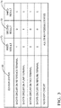
- Fig. 3 is a table that summarizes test-result logic versus the sensor-status 30 that is performed by the controller 26.
- the three amplifiers shown in Fig. 1 are for illustration purposes only. One skilled in the art will recognize that the three amplifiers may be replaced by one amplifier by using multiple switching-devices to connect the amplifier to the desired sensor-terminals as determined by the controller 26, as illustrated in Fig. 4 .
- Fig. 4 illustrates a non-limiting example of a second embodiment of the device 10 that may be used to pinpoint short-circuits in the WRAF-sensor 12. It will be understood by those in the art that the controller 26 may control the various switches and transistors to perform the tests described herein.
- the switches used to connect the current-sink 24, the amplifiers, and the test-resistors may be any switches suitable for use in an automotive application, and may include, but are not limited to, relays, thyristors, and transistors, as will be recognized by one skilled in the art of electronics.
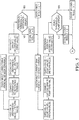
- Fig. 5 illustrates a flow-chart of a logic used by the controller 26 to determine the various status-values 28 and the sensor-status 30 as described above.
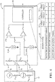
- Fig. 6 illustrates a non-limiting example of a third embodiment of the device 10 that is designed to test another WRAF-sensor 12 to detect various short-to-ground and short-to-battery conditions.
- the device 10 includes input-channels 14 for connecting to the WRAF-sensor 12 at a reference-terminal 16, a pump-terminal 18, and a return-terminal 20.
- the table shown at the bottom of the drawing may be performed by software or other logic inside the controller 26.
- Fig. 7 illustrates a non-limiting example of a fourth embodiment of the device 10 that is designed to test yet another WRAF-sensor 12 to detect various short-to-ground and short-to-battery conditions.
- the device 10 includes input-channels 14 for connecting to the WRAF-sensor 12 at a pump-terminal 18 and a return-terminal 20.
- the table shown at the bottom of the drawing may be performed by software or other logic inside the controller 26.
- a short-circuit pinpointing device 10 and a controller 26 for the short-circuit pinpointing device 10 is provided.
- the device 10 enables the reliable and accurate determination of the location of the short-circuit at any sensor-terminal using one electronic circuit over all the sensors' operating temperatures.
- the circuit is immune to any absolute circuit imperfection and non-idealities. Further, any component mismatches and all other errors at the input sensing stage are cancelled and do not affect the integrity of the pinpointing function.
Landscapes
- Engineering & Computer Science (AREA)
- Physics & Mathematics (AREA)
- General Physics & Mathematics (AREA)
- Chemical & Material Sciences (AREA)
- Combustion & Propulsion (AREA)
- Mechanical Engineering (AREA)
- General Engineering & Computer Science (AREA)
- Testing Of Short-Circuits, Discontinuities, Leakage, Or Incorrect Line Connections (AREA)
Abstract
Description
- This disclosure generally relates to a short-circuit pinpointing device, and more particularly relates to a short-circuit pinpointing device for testing a wide-range air-fuel sensor.
- It is desirable to diagnose a short-circuit to a battery and/or a ground of an air-fuel sensor in an automotive application. A wide-range air-fuel sensor typically has several electrical wires that may become short-circuited to the battery or ground. Difficulty in determining which sensor wire is short-circuited may be caused by the internal cell bias voltage from the reference and pump cells, battery and ground voltage fluctuations, and large common-mode signals. Additionally, it is advantageous to be able to pinpoint a short-circuit while the sensor is at operating temperature, of which the prior art is incapable.
- In accordance with one embodiment, a short-circuit pinpointing device for testing a wide-range air/fuel sensor is provided. The short-circuit pinpointing device includes a current-sink and a controller. The current-sink is selectively connectable to one or more of sensor-terminals of the wide-range air/fuel sensor that include a reference-terminal, a pump-terminal, a return-terminal, and a tag-terminal. The controller is in communication with the current-sink and the sensor-terminals. The controller controls the connection of the current-sink to the one or more sensor-terminals. The controller also determines one or more status-values based on signals present at the sensor-terminals. The controller also determines a sensor-status of the wide-range air/fuel sensor based on the connection of the current-sink and the one or more status-values.
Moreover the short-circuit pinpointing device comprises a current-sink that is selectively connectable to one or more of sensor-terminals of a wide-range air/fuel sensor that include a reference-terminal, a pump-terminal, a return-terminal, and a tag-terminal and a controller in communication with the current-sink and the sensor-terminals, wherein the controller controls a connection of the current-sink to the one or more sensor-terminals, determines one or more status-values based on signals present at the sensor-terminals, and determines a sensor-status of the wide-range air/fuel sensor based on the connection of the current-sink and the one or more status-values. The controller determines a first-value based on a difference between signals at the reference-terminal and the return-terminal while the current-sink is disconnected. Moreover the controller determines a second-value based on the difference between signals at the reference-terminal and the return-terminal while the current-sink is connected to the reference-terminal. The controller determines a reference-error based on the difference between the second-value and the first-value, and determines that a short-circuit is present on the reference-terminal when a reference-threshold is greater than the reference-error. The short-circuit pinpointing device includes three test-resistors that are each selectively connectable between two of the sensor-terminals, wherein the controller controls the connection of the test-resistor between the two sensor-terminals.
A first-test-resistor is connected between the reference-terminal and the return-terminal, a second-test-resistor is connected between the return-terminal and the pump-terminal, and a third-test-resistor is connected between the pump-terminal and the tag-terminal. Moreover the controller determines a third-value based on a difference between signals at the pump-terminal and the return-terminal while the current-sink is disconnected. The controller determines a fourth-value based on the difference between signals at the pump-terminal and the return-terminal while the current-sink is connected to the pump-terminal. The controller determines a pump-error based on the difference between the fourth-value and the third-value, and determines that a short-circuit is present on the pump-terminal when a pump-threshold is greater than the pump-error. the short-circuit pinpointing device includes three test-resistors that are selectively connectable between two of the sensor-terminals, wherein the controller controls the connection of the test-resistor between the two sensor-terminals. A first-test-resistor is not connected between the reference-terminal and the return-terminal, a second-test-resistor is connected between the return-terminal and the pump-terminal, and a third-test-resistor is connected between the pump-terminal and the tag-terminal. Furthermore the controller determines a fifth-value based on a difference between signals at the tag-terminal and the pump-terminal while the current-sink is disconnected. The controller determines a sixth-value based on the difference between signals at the tag-terminal and the pump-terminal while the current-sink is connected to the tag-terminal determines a tag-error based on the difference between the sixth-value and the fifth-value, and determines that a short-circuit is present on the tag-terminal when a tag-threshold is greater than the tag-error. In addition the short-circuit pinpointing device includes three test-resistors that are selectively connectable between two of the sensor-terminals, wherein the controller controls the connection of the test-resistor between the two sensor-terminals. A first-test-resistor is not connected between the reference-terminal and the return-terminal. A second-test-resistor is connected between the return-terminal and the pump-terminal, and a third-test-resistor is connected between the pump-terminal and the tag-terminal. The controller determines a first-value based on a difference between signals at the reference-terminal and the return-terminal while the current-sink is disconnected, determines a second-value based on the difference between signals at the reference-terminal and the return-terminal while the current-sink is connected to the reference-terminal. The controller determines a reference-error based on the difference between the second-value and the first-value, and determines that a short-circuit is present on the reference-terminal when a reference-threshold is greater than the reference-error, and wherein the controller determines a third-value based on the difference between signals at the pump-terminal and the return-terminal while the current-sink is disconnected. The controller determines a fourth-value based on the difference between signals at the pump-terminal and the return-terminal while the current-sink is connected to the pump-terminal, determines a pump-error based on the difference between the fourth-value and the third-value, and determines that the short-circuit is present on the pump-terminal when a pump-threshold is greater than the pump-error. The controller determines a fifth-value based on the difference between signals at the tag-terminal and the pump-terminal while the current-sink is disconnected. Moreover the controller determines a sixth-value based on the difference between signals at the tag-terminal and the pump-terminal while the current-sink is connected to the tag-terminal. Furthermore the controller determines a tag-error based on the difference between the sixth-value and the fifth-value The controller determines that the short-circuit is present on the tag-terminal when a tag-threshold is greater than the tag-error, and wherein the controller determines that the short-circuit is present on the return-terminal when the reference-error is greater than the reference-threshold and when the pump-error is greater than the pump-threshold and when the tag-error is greater than the tag-threshold. The short-circuit pinpointing device includes three test-resistors that are selectively connectable between two of the sensor-terminals, wherein the controller controls the connection of the test-resistor between the two sensor-terminals. A first-test-resistor is connected between the reference-terminal and the return-terminal, a second-test-resistor is connected between the return-terminal and the pump-terminal, and a third-test-resistor is connected between the pump-terminal and the tag-terminal when the first-value and the second-value are determined. The first-test-resistor is not connected between the reference-terminal and the return-terminal, the second-test-resistor is connected between the return-terminal and the pump-terminal, and the third-test-resistor is connected between the pump-terminal and the tag-terminal when the third-value, the fourth-value, the fifth-value and the sixth-value are determined. - Further features and advantages will appear more clearly on a reading of the following detailed description of the preferred embodiment, which is given by way of non-limiting example only and with reference to the accompanying drawings.
- The present invention will now be described, by way of example with reference to the accompanying drawings, in which:
-
Fig. 1 is an illustration of a short-circuit pinpointing device in accordance with a first embodiment; -
Fig. 2 is an illustration of a controller for the short-circuit pinpointing device ofFig. 1 in accordance with the invention; -
Fig. 3 is a table that summarizes a test-result logic versus a sensor-status in accordance with the invention; -
Fig. 4 is an illustration of a short-circuit pinpointing device in accordance with a second embodiment; -
Fig. 5 is a flow chart illustrating a logic used by the controller in accordance with the invention; -
Fig. 6 is an illustration of a short-circuit pinpointing device in accordance with a third embodiment; and -
Fig. 7 is an illustration of a short-circuit pinpointing device in accordance with a fourth embodiment. -
Fig. 1 illustrates a non-limiting example of a first embodiment of a short-circuit pinpointing device 10, hereafter referred to as thedevice 10, that is designed to test a wide-range air/fuel sensor 12 (WRAF-sensor 12) to detect various short-to-ground and short-to-battery conditions. Thedevice 10 includes input-channels 14 for connecting to the WRAF-sensor 12 at a reference-terminal 16, a pump-terminal 18, a return-terminal 20, and a tag-terminal 22. The WRAF-sensor 12 may include an additional ground-terminal (not shown) as will be recognized by those in the art. - The
device 10 also includes a current-sink 24 that is selectively connectable to one or more of the WRAF-sensor 12 terminals described above. The current-sink 24 may be any current-sink 24 suitable for use in an automotive application and may produce an electrical current in the range of 400 micro-amps (µA) to 600µA. WhileFig. 1 illustrates multiple current-sinks attached to the WRAF-sensor 12 terminals, it will be recognized by those in the art that a single current-sink 24 may be used with multiple switching-devices attached to the WRAF-sensor 12 terminals. - The
device 10 also includes acontroller 26 in communication with the current-sink 24 and the WRAF-sensor 12 terminals. Thecontroller 26 may control the connection of the current-sink 24 to the one or more sensor-terminals to determine one or more status-values 28 (Fig.2 ) of the WRAF-sensor 12 based on signals present at the sensor-terminals. Thecontroller 26 may also determine a sensor-status 30 (Fig.2 ) of the WRAF-sensor 12 based on the connection of the current-sink 24 and the one or more status-values 28, as will be described in more detail below. - The
controller 26 may include a processor (not shown) such as a microprocessor or other control circuitry such as analog and/or digital control circuitry including an application specific integrated circuit (ASIC) for processing data as should be evident to those in the art. Thecontroller 26 may include memory, including nonvolatile memory, such as electrically erasable programmable read-only memory (EEPROM) for storing one or more routines, threshold-values, and captured data. The one or more routines may be executed by the processor to perform steps for determining if signals received by thecontroller 26 indicate the presence of short-circuits as described herein. - The
controller 26 may determine a first-value 32 based on a difference between signals at the reference-terminal 16 and the return-terminal 20 while the current-sink 24 is disconnected as indicated by the open switch S_ref(Fig. 1 ). The controller may then close switch S_ref connecting the current-sink 24 to the reference-terminal 16 and may determine a second-value 34 based on a difference between signals at the reference-terminal 16 and the return-terminal 20. It will be recognized by one skilled in the art that the two switches connecting a first-amplifier 36 to the reference-terminal 16 and the return-terminal 20, and the switch connected to the output of the first-amplifier 36, are closed by thecontroller 26 in order to determine the first-value 32 and the second-value 34. Thecontroller 26 may then determine a reference-error 38 based on the difference between the second-value 34 and the first-value 32, and may store a first-result 70 as a logical '1' when a reference-threshold 40 is greater than the reference-error 38. The controller may also store the first-result 70 as a logical '0' when the reference-threshold 40 is not greater than the reference-error 38. - The
device 10 may also include three test-resistors that are each selectively connectable between two of the sensor-terminals, wherein the controller controls the connection of the test-resistor between the two sensor-terminals, as illustrated inFig. 1 . A first-test-resistor 42 may be connected between the reference-terminal 16 and the return-terminal 20, a second-test-resistor 44 may be connected between the return-terminal 20 and the pump-terminal 18, and a third-test-resistor 46 may be connected between the pump-terminal 18 and the tag-terminal 22 while the first-value 32 and the second-value 34 are determined. The three test-resistors may be any resistor suitable for use in an automotive application and preferably each have a resistance of 1000-ohms. - The
controller 26 may also determine a third-value 48 based on a difference between signals at the pump-terminal 18and the return-terminal 20 while the current-sink 24 is disconnected as indicated by the open switch S_pump. The controller may then close switch S_pump connecting the current-sink 24 to the pump-terminal 18 and may determine a fourth-value 50 based on a difference between signals at the pump-terminal 18 and the return-terminal 20. It will be recognized by one skilled in the art that the two switches connecting a second-amplifier 52 to the return-terminal 20 and the pump-terminal 18, and the switch connected to the output of the second-amplifier 52, are closed by thecontroller 26 in order to determine the third-value 48 and the fourth-value 50. Thecontroller 26 may then determine a pump-error 54 based on the difference between the fourth-value 50 and the third-value 48, and may store a second-result 72 as a logical '1' when a pump-threshold 56 is greater than the pump-error 54. The controller may also store the second-result 72 as a logical '0' when the pump-threshold 56 is not greater than the pump-error 54. - While the third-
value 48 and the fourth-value 50 are determined by thecontroller 26, the first-test-resistor 42 may not be connected between the reference-terminal 16 and the return-terminal 20, the second-test-resistor 44 may be connected between the return-terminal 20 and the pump-terminal 18, and the third-test-resistor 46 may be connected between the pump-terminal 18 and the tag-terminal 22. - The
controller 26 may also determine a fifth-value 58 based on a difference between signals at the tag-terminal 22 and the pump-terminal 18 while the current-sink 24 is disconnected as indicated by the open switch S_tag. Thecontroller 26 may then close switch S_tag connecting the current-sink 24 to the tag-terminal 22 and may determine a sixth-value 60 based on a difference between signals at the tag-terminal 22 and the pump-terminal 18. It will be recognized by one skilled in the art that the two switches connecting a third-amplifier 62 to the pump-terminal 18 and the tag-terminal 22, and the switch connected to the output of the third-amplifier 62, are closed by thecontroller 26 in order to determine the fifth-value 58 and the sixth-value 60. Thecontroller 26 may then determine a tag-error 64 based on the difference between the sixth-value 60 and the fifth-value 58, and may store a third-result 74 as a logical '1' when a tag-threshold 66 is greater than the tag-error 64. Thecontroller 26 may also store the third-result 74 as a logical '0' when the tag-threshold 66 is not greater than the tag-error 64. - While the fifth-
value 58 and the sixth-value 60 are determined by thecontroller 26, the first-test-resistor 42 may not be connected between the reference-terminal 16 and the return-terminal 20, the second-test-resistor 44 may be connected between the return-terminal 20 and the pump-terminal 18, and the third-test-resistor 46 may be connected between the pump-terminal 18 and the tag-terminal 22. - If the stored test-results are such that the first-
result 70 is logical '1', the second-result 72 is logical '0', and the third-result 74 is logical '0', then thecontroller 26 assigns a sensor-status 30 indicative of a short-circuit on the reference-terminal 16. If the stored test-results are such that the first-result 70 is logical '0', the second-result 72 is logical '1', and the third-result 74 is logical '0', then thecontroller 26 assigns a sensor-status 30 indicative of a short-circuit on the pump-terminal 18. If the stored test-results are such that the first-result 70 is logical '0', the second-result 72 is logical '0', and the third-result 74 is logical '1', then thecontroller 26 assigns a sensor-status 30 indicative of a short-circuit on the tag-terminal 22. If the stored test-results are such that the first-result 70 is logical '0', the second-result 72 is logical '0', and the third-result 74 is logical '0', then thecontroller 26 assigns a sensor-status 30 indicative of a short-circuit on the return-terminal 20.Fig. 3 is a table that summarizes test-result logic versus the sensor-status 30 that is performed by thecontroller 26. - It will be recognized by one skilled in the art that the determination of the status-
values 28 described above may be performed by thecontroller 26 independently and in any order. - The three amplifiers shown in
Fig. 1 are for illustration purposes only. One skilled in the art will recognize that the three amplifiers may be replaced by one amplifier by using multiple switching-devices to connect the amplifier to the desired sensor-terminals as determined by thecontroller 26, as illustrated inFig. 4 . -
Fig. 4 illustrates a non-limiting example of a second embodiment of thedevice 10 that may be used to pinpoint short-circuits in the WRAF-sensor 12. It will be understood by those in the art that thecontroller 26 may control the various switches and transistors to perform the tests described herein. - The switches used to connect the current-
sink 24, the amplifiers, and the test-resistors may be any switches suitable for use in an automotive application, and may include, but are not limited to, relays, thyristors, and transistors, as will be recognized by one skilled in the art of electronics. -
Fig. 5 illustrates a flow-chart of a logic used by thecontroller 26 to determine the various status-values 28 and the sensor-status 30 as described above. -
Fig. 6 illustrates a non-limiting example of a third embodiment of thedevice 10 that is designed to test another WRAF-sensor 12 to detect various short-to-ground and short-to-battery conditions. Thedevice 10 includes input-channels 14 for connecting to the WRAF-sensor 12 at a reference-terminal 16, a pump-terminal 18, and a return-terminal 20. The table shown at the bottom of the drawing may be performed by software or other logic inside thecontroller 26. -
Fig. 7 illustrates a non-limiting example of a fourth embodiment of thedevice 10 that is designed to test yet another WRAF-sensor 12 to detect various short-to-ground and short-to-battery conditions. Thedevice 10 includes input-channels 14 for connecting to the WRAF-sensor 12 at a pump-terminal 18 and a return-terminal 20. The table shown at the bottom of the drawing may be performed by software or other logic inside thecontroller 26. - Accordingly, a short-
circuit pinpointing device 10, and acontroller 26 for the short-circuit pinpointing device 10 is provided. Thedevice 10 enables the reliable and accurate determination of the location of the short-circuit at any sensor-terminal using one electronic circuit over all the sensors' operating temperatures. The circuit is immune to any absolute circuit imperfection and non-idealities. Further, any component mismatches and all other errors at the input sensing stage are cancelled and do not affect the integrity of the pinpointing function. - While this invention has been described in terms of the preferred embodiments thereof, it is not intended to be so limited, but rather only to the extent set forth in the claims that follow. Moreover, the use of the terms first, second, upper, lower, etc. does not denote any order of importance, location, or orientation, but rather the terms first, second, etc. are used to distinguish one element from another. Furthermore, the use of the terms a, an, etc. do not denote a limitation of quantity, but rather denote the presence of at least one of the referenced items.
Claims (13)
- A short-circuit pinpointing device (10) for testing a wide-range air/fuel sensor (12), said device (10) comprising:a current-sink (24) that is selectively connectable to one or more of sensor-terminals of a wide-range air/fuel sensor (12) that include a reference-terminal (16), a pump-terminal (18), a return-terminal (20), and a tag-terminal (22); anda controller (26) in communication with the current-sink (24) and the sensor-terminals, wherein the controller (26) controls a connection of the current-sink (24) to the one or more sensor-terminals, determines one or more status-values (28) based on signals present at the sensor-terminals, and determines a sensor-status (30) of the wide-range air/fuel sensor (12) based on the connection of the current-sink (24) and the one or more status-values (28).
- The device (10) in accordance with claim 1, wherein the controller (26) determines a first-value (32) based on a difference between signals at the reference-terminal (16) and the return-terminal (20) while the current-sink (24) is disconnected, determines a second-value (34) based on the difference between signals at the reference-terminal (16) and the return-terminal (20) while the current-sink (24) is connected to the reference-terminal (16), determines a reference-error (38) based on the difference between the second-value (34) and the first-value (32), and determines that a short-circuit is present on the reference-terminal (16) when a reference-threshold (40) is greater than the reference-error (38).
- The device (10) in accordance with any one of claims 1 to 2, wherein the device (10) includes three test-resistors that are each selectively connectable between two of the sensor-terminals, wherein the controller (26) controls the connection of the test-resistor between the two sensor-terminals.
- The device (10) in accordance with any one of claims 1 to 3, wherein a first-test-resistor (42) is connected between the reference-terminal (16) and the return-terminal (20), a second-test-resistor (44) is connected between the return-terminal (20) and the pump-terminal (18), and a third-test-resistor (46) is connected between the pump-terminal (18) and the tag-terminal (22).
- The device (10) in accordance with any one of claims 1 to 4, wherein the controller (26) determines a third-value (48) based on a difference between signals at the pump-terminal (18) and the return-terminal (20) while the current-sink (24) is disconnected, determines a fourth-value (50) based on the difference between signals at the pump-terminal (18) and the return-terminal (20) while the current-sink (24) is connected to the pump-terminal (18), determines a pump-error (54) based on the difference between the fourth-value (50) and the third-value (48), and determines that a short-circuit is present on the pump-terminal (18) when a pump-threshold (56) is greater than the pump-error (54).
- The device (10) in accordance with claim 5, wherein the device (10) includes three test-resistors that are selectively connectable between two of the sensor-terminals, wherein the controller (26) controls the connection of the test-resistor between the two sensor-terminals.
- The device (10) in accordance with claim 6, wherein a first-test-resistor (42) is not connected between the reference-terminal (16) and the return-terminal (20), a second-test-resistor (44) is connected between the return-terminal (20) and the pump-terminal (18), and a third-test-resistor (46) is connected between the pump-terminal (18) and the tag-terminal (22).
- The device (10) in accordance with any one of claims 1 to 7, wherein the controller (26) determines a fifth-value (58) based on a difference between signals at the tag-terminal (22) and the pump-terminal (18) while the current-sink (24) is disconnected, determines a sixth-value (60) based on the difference between signals at the tag-terminal (22) and the pump-terminal (18) while the current-sink (24) is connected to the tag-terminal (22), determines a tag-error (64) based on the difference between the sixth-value (60) and the fifth-value (58), and determines that a short-circuit is present on the tag-terminal (22) when a tag-threshold (66) is greater than the tag-error (64).
- The device (10) in accordance with claim 8, wherein the device (10) includes three test-resistors that are selectively connectable between two of the sensor-terminals, wherein the controller (26) controls the connection of the test-resistor between the two sensor-terminals.
- The device (10) in accordance with claim 9, wherein a first-test-resistor (42) is not connected between the reference-terminal (16) and the return-terminal (20), a second-test-resistor (44) is connected between the return-terminal (20) and the pump-terminal (18), and a third-test-resistor (46) is connected between the pump-terminal (18) and the tag-terminal (22).
- The device (10) in accordance with any one of claims 1 to 11, wherein the controller (26) determines a first-value (32) based on a difference between signals at the reference-terminal (16) and the return-terminal (20) while the current-sink (24) is disconnected, determines a second-value (34) based on the difference between signals at the reference-terminal (16) and the return-terminal (20) while the current-sink (24) is connected to the reference-terminal (16), determines a reference-error (38) based on the difference between the second-value (34) and the first-value (32), and determines that a short-circuit is present on the reference-terminal (16) when a reference-threshold (40) is greater than the reference-error (38), and wherein the controller (26) determines a third-value (48) based on the difference between signals at the pump-terminal (18) and the return-terminal (20) while the current-sink (24) is disconnected, determines a fourth-value (50) based on the difference between signals at the pump-terminal (18) and the return-terminal (20) while the current-sink (24) is connected to the pump-terminal (18), determines a pump-error (54) based on the difference between the fourth-value (50) and the third-value (48), and determines that the short-circuit is present on the pump-terminal (18) when a pump-threshold (56) is greater than the pump-error (54), and wherein the controller (26) determines a fifth-value (58) based on the difference between signals at the tag-terminal (22) and the pump-terminal (18) while the current-sink (24) is disconnected, determines a sixth-value (60) based on the difference between signals at the tag-terminal (22) and the pump-terminal (18) while the current-sink (24) is connected to the tag-terminal (22), determines a tag-error (64) based on the difference between the sixth-value (60) and the fifth-value (58), and determines that the short-circuit is present on the tag-terminal (22) when a tag-threshold (66) is greater than the tag-error (64), and wherein the controller (26) determines that the short-circuit is present on the return-terminal (20) when the reference-error (38) is greater than the reference-threshold (40) and when the pump-error (54) is greater than the pump-threshold (56) and when the tag-error (64) is greater than the tag-threshold (66).
- The device (10) in accordance with claim 11, wherein the device (10) includes three test-resistors that are selectively connectable between two of the sensor-terminals, wherein the controller (26) controls the connection of the test-resistor between the two sensor-terminals.
- The device (10) in accordance with claim 12, wherein a first-test-resistor (42) is connected between the reference-terminal (16) and the return-terminal (20), a second-test-resistor (44) is connected between the return-terminal (20) and the pump-terminal (18), and a third-test-resistor (46) is connected between the pump-terminal (18) and the tag-terminal (22) when the first-value (32) and the second-value (34) are determined, and wherein the first-test-resistor (42) is not connected between the reference-terminal (16) and the return-terminal (20), the second-test-resistor (44) is connected between the return-terminal (20) and the pump-terminal (18), and the third-test-resistor (46) is connected between the pump-terminal (18) and the tag-terminal (22) when the third-value (48), the fourth-value (50), the fifth-value (58) and the sixth-value (60) are determined.
Applications Claiming Priority (1)
| Application Number | Priority Date | Filing Date | Title |
|---|---|---|---|
| US15/444,835 US10371736B2 (en) | 2017-02-28 | 2017-02-28 | Short-circuit pinpointing device |
Publications (2)
| Publication Number | Publication Date |
|---|---|
| EP3385732A1 true EP3385732A1 (en) | 2018-10-10 |
| EP3385732B1 EP3385732B1 (en) | 2022-06-08 |
Family
ID=61256815
Family Applications (1)
| Application Number | Title | Priority Date | Filing Date |
|---|---|---|---|
| EP18158123.2A Active EP3385732B1 (en) | 2017-02-28 | 2018-02-22 | Short-circuit pinpointing device |
Country Status (3)
| Country | Link |
|---|---|
| US (2) | US10371736B2 (en) |
| EP (1) | EP3385732B1 (en) |
| CN (1) | CN108508316B (en) |
Cited By (1)
| Publication number | Priority date | Publication date | Assignee | Title |
|---|---|---|---|---|
| DE102018215887A1 (en) * | 2018-09-19 | 2020-03-19 | Continental Automotive Gmbh | Method and device for diagnosing an exhaust gas sensor |
Families Citing this family (3)
| Publication number | Priority date | Publication date | Assignee | Title |
|---|---|---|---|---|
| DE102017214205A1 (en) * | 2017-08-15 | 2019-02-21 | Robert Bosch Gmbh | Control unit with circuit and method for short-circuit protection of ground lines and sensors |
| DE102019204827A1 (en) * | 2019-04-04 | 2020-10-08 | Robert Bosch Gmbh | Method for diagnosing exhaust gas sensors |
| EP3875951B1 (en) * | 2020-03-06 | 2025-12-03 | Robert Bosch GmbH | Evaluation and control unit for a gas sensor |
Citations (4)
| Publication number | Priority date | Publication date | Assignee | Title |
|---|---|---|---|---|
| US20050288847A1 (en) * | 2004-06-29 | 2005-12-29 | Ngk Spark Plug Co., Ltd. | Abnormality diagnosis method and apparatus for gas concentration measuring device |
| US20060219553A1 (en) * | 2005-03-30 | 2006-10-05 | Ngk Spark Plug Co., Ltd. | Gas detection apparatus, gas-sensor control circuit used for gas detection apparatus, and inspection method for gas detection apparatus |
| US20120001641A1 (en) * | 2009-01-07 | 2012-01-05 | Ngk Spark Plug Co., Ltd. | Gas sensor control apparatus and method |
| US20130234744A1 (en) * | 2012-03-06 | 2013-09-12 | MAGNETI MARELLI S.p.A. | Diagnosis method and control unit for performing a diagnosis of a lambda sensor of the UEGO type of an exhaust system for an internal combustion engine |
Family Cites Families (11)
| Publication number | Priority date | Publication date | Assignee | Title |
|---|---|---|---|---|
| CN100578247C (en) | 2006-06-30 | 2010-01-06 | 台达电子工业股份有限公司 | Motor testing method and circuit |
| JP4157576B2 (en) * | 2006-09-25 | 2008-10-01 | 三菱電機株式会社 | Engine control device |
| CN201269862Y (en) * | 2008-09-24 | 2009-07-08 | 比亚迪股份有限公司 | Failure monitoring apparatus for oxygen sensor |
| DE102009027378A1 (en) | 2009-07-01 | 2011-01-05 | Robert Bosch Gmbh | Method and diagnostic device for diagnosing a heated exhaust gas probe of an internal combustion engine |
| DE102009050221A1 (en) * | 2009-10-22 | 2011-05-05 | Continental Automotive Gmbh | Device and method for the diagnosis of an exhaust gas sensor |
| KR101891163B1 (en) * | 2012-04-04 | 2018-08-24 | 에스케이하이닉스 주식회사 | Test circuit and semiconductor apparatus including the same |
| US9285412B2 (en) * | 2012-09-20 | 2016-03-15 | Dialog Semiconductor Gmbh | High speed, high current, closed loop load transient tester |
| JP6214975B2 (en) * | 2013-09-10 | 2017-10-18 | 日本特殊陶業株式会社 | Load drive device and sensor control device |
| FR3017959B1 (en) * | 2014-02-24 | 2017-08-25 | Lohr Electromecanique | METHOD FOR DETECTING A SHORT CIRCUIT IN A SYNCHRONOUS MACHINE EQUIPPED WITH AN ANGULAR POSITION SENSOR |
| JP6362643B2 (en) * | 2016-07-19 | 2018-07-25 | 株式会社デンソーテン | Air-fuel ratio sensor control device and abnormality detection method |
| JP6673194B2 (en) * | 2016-12-27 | 2020-03-25 | 株式会社デンソー | Air-fuel ratio sensor control device |
-
2017
- 2017-02-28 US US15/444,835 patent/US10371736B2/en active Active
-
2018
- 2018-02-22 EP EP18158123.2A patent/EP3385732B1/en active Active
- 2018-02-27 CN CN201810164224.4A patent/CN108508316B/en active Active
-
2019
- 2019-06-19 US US16/446,122 patent/US10788541B2/en active Active
Patent Citations (4)
| Publication number | Priority date | Publication date | Assignee | Title |
|---|---|---|---|---|
| US20050288847A1 (en) * | 2004-06-29 | 2005-12-29 | Ngk Spark Plug Co., Ltd. | Abnormality diagnosis method and apparatus for gas concentration measuring device |
| US20060219553A1 (en) * | 2005-03-30 | 2006-10-05 | Ngk Spark Plug Co., Ltd. | Gas detection apparatus, gas-sensor control circuit used for gas detection apparatus, and inspection method for gas detection apparatus |
| US20120001641A1 (en) * | 2009-01-07 | 2012-01-05 | Ngk Spark Plug Co., Ltd. | Gas sensor control apparatus and method |
| US20130234744A1 (en) * | 2012-03-06 | 2013-09-12 | MAGNETI MARELLI S.p.A. | Diagnosis method and control unit for performing a diagnosis of a lambda sensor of the UEGO type of an exhaust system for an internal combustion engine |
Cited By (2)
| Publication number | Priority date | Publication date | Assignee | Title |
|---|---|---|---|---|
| DE102018215887A1 (en) * | 2018-09-19 | 2020-03-19 | Continental Automotive Gmbh | Method and device for diagnosing an exhaust gas sensor |
| US12216180B2 (en) | 2018-09-19 | 2025-02-04 | Vitesco Technologies GmbH | Method and apparatus for diagnosing an exhaust gas sensor |
Also Published As
| Publication number | Publication date |
|---|---|
| CN108508316B (en) | 2021-06-11 |
| US10371736B2 (en) | 2019-08-06 |
| CN108508316A (en) | 2018-09-07 |
| US10788541B2 (en) | 2020-09-29 |
| US20190302165A1 (en) | 2019-10-03 |
| EP3385732B1 (en) | 2022-06-08 |
| US20180246157A1 (en) | 2018-08-30 |
Similar Documents
| Publication | Publication Date | Title |
|---|---|---|
| US10788541B2 (en) | Method for pinpointing a short-circuit | |
| US7415343B2 (en) | Engine controller | |
| US9389128B2 (en) | Temperature detection device | |
| US9170229B2 (en) | Method for diagnosing an electrical contact connection of an exhaust gas sensor | |
| US9618395B2 (en) | Temperature detecting circuit | |
| US9726705B2 (en) | Sensor interface circuits | |
| CN107478992B (en) | Voltage detection and judgment circuit and power battery system with same | |
| US20170059437A1 (en) | Systems and methods that allow for simultaneous sensor and signal conditioning circuit performance testing | |
| US20070183478A1 (en) | RTD measurement unit including detection mechanism for automatic selection of 3-wire or 4-wire RTD measurement mode | |
| CN206208410U (en) | Motor temperature sample circuit and the electric automobile with it | |
| CN115267493A (en) | Pin state detection device, method and programmer | |
| CN111308370A (en) | Voltage detection circuit, method, circuit board, device and vehicle air conditioner | |
| US20130249564A1 (en) | System and method to detect a short to ground of an external sensor return line | |
| KR102717953B1 (en) | How to diagnose exhaust gas sensor | |
| CN111044913B (en) | Method for operating a battery sensor and battery sensor | |
| CA1072637A (en) | Source related potential indicating continuity tester | |
| US12429453B2 (en) | Evaluation and control unit for a gas sensor | |
| CN215728610U (en) | Test system | |
| US12392836B2 (en) | Battery sensor | |
| US11656284B2 (en) | Method for operating a battery sensor, and battery sensor | |
| JP4824504B2 (en) | Temperature sensor control device | |
| CN112858934B (en) | Method for testing battery sensor, and battery sensor | |
| US12360010B2 (en) | Method for diagnosing a wideband lambda sensor | |
| US20260063732A1 (en) | Module, system and method for detecting a string fault | |
| CN109115247B (en) | System and method for monitoring connection between sensor and connector |
Legal Events
| Date | Code | Title | Description |
|---|---|---|---|
| PUAI | Public reference made under article 153(3) epc to a published international application that has entered the european phase |
Free format text: ORIGINAL CODE: 0009012 |
|
| STAA | Information on the status of an ep patent application or granted ep patent |
Free format text: STATUS: THE APPLICATION HAS BEEN PUBLISHED |
|
| AK | Designated contracting states |
Kind code of ref document: A1 Designated state(s): AL AT BE BG CH CY CZ DE DK EE ES FI FR GB GR HR HU IE IS IT LI LT LU LV MC MK MT NL NO PL PT RO RS SE SI SK SM TR |
|
| AX | Request for extension of the european patent |
Extension state: BA ME |
|
| STAA | Information on the status of an ep patent application or granted ep patent |
Free format text: STATUS: REQUEST FOR EXAMINATION WAS MADE |
|
| 17P | Request for examination filed |
Effective date: 20190410 |
|
| RBV | Designated contracting states (corrected) |
Designated state(s): AL AT BE BG CH CY CZ DE DK EE ES FI FR GB GR HR HU IE IS IT LI LT LU LV MC MK MT NL NO PL PT RO RS SE SI SK SM TR |
|
| REG | Reference to a national code |
Ref country code: DE Ref legal event code: R079 Ref document number: 602018036396 Country of ref document: DE Free format text: PREVIOUS MAIN CLASS: G01R0031020000 Ipc: G01R0031520000 |
|
| GRAP | Despatch of communication of intention to grant a patent |
Free format text: ORIGINAL CODE: EPIDOSNIGR1 |
|
| RIC1 | Information provided on ipc code assigned before grant |
Ipc: F02D 41/14 20060101ALI20220204BHEP Ipc: G01R 31/52 20200101AFI20220204BHEP |
|
| STAA | Information on the status of an ep patent application or granted ep patent |
Free format text: STATUS: GRANT OF PATENT IS INTENDED |
|
| INTG | Intention to grant announced |
Effective date: 20220317 |
|
| RIN1 | Information on inventor provided before grant (corrected) |
Inventor name: GOSE, MARK W. Inventor name: PENROD, DANIEL C. Inventor name: ZARABADI, SEYED R. |
|
| GRAS | Grant fee paid |
Free format text: ORIGINAL CODE: EPIDOSNIGR3 |
|
| GRAA | (expected) grant |
Free format text: ORIGINAL CODE: 0009210 |
|
| STAA | Information on the status of an ep patent application or granted ep patent |
Free format text: STATUS: THE PATENT HAS BEEN GRANTED |
|
| AK | Designated contracting states |
Kind code of ref document: B1 Designated state(s): AL AT BE BG CH CY CZ DE DK EE ES FI FR GB GR HR HU IE IS IT LI LT LU LV MC MK MT NL NO PL PT RO RS SE SI SK SM TR |
|
| REG | Reference to a national code |
Ref country code: AT Ref legal event code: REF Ref document number: 1497291 Country of ref document: AT Kind code of ref document: T Effective date: 20220615 Ref country code: CH Ref legal event code: EP |
|
| REG | Reference to a national code |
Ref country code: DE Ref legal event code: R096 Ref document number: 602018036396 Country of ref document: DE |
|
| REG | Reference to a national code |
Ref country code: IE Ref legal event code: FG4D |
|
| REG | Reference to a national code |
Ref country code: LT Ref legal event code: MG9D |
|
| REG | Reference to a national code |
Ref country code: NL Ref legal event code: MP Effective date: 20220608 |
|
| PG25 | Lapsed in a contracting state [announced via postgrant information from national office to epo] |
Ref country code: SE Free format text: LAPSE BECAUSE OF FAILURE TO SUBMIT A TRANSLATION OF THE DESCRIPTION OR TO PAY THE FEE WITHIN THE PRESCRIBED TIME-LIMIT Effective date: 20220608 Ref country code: NO Free format text: LAPSE BECAUSE OF FAILURE TO SUBMIT A TRANSLATION OF THE DESCRIPTION OR TO PAY THE FEE WITHIN THE PRESCRIBED TIME-LIMIT Effective date: 20220908 Ref country code: LT Free format text: LAPSE BECAUSE OF FAILURE TO SUBMIT A TRANSLATION OF THE DESCRIPTION OR TO PAY THE FEE WITHIN THE PRESCRIBED TIME-LIMIT Effective date: 20220608 Ref country code: HR Free format text: LAPSE BECAUSE OF FAILURE TO SUBMIT A TRANSLATION OF THE DESCRIPTION OR TO PAY THE FEE WITHIN THE PRESCRIBED TIME-LIMIT Effective date: 20220608 Ref country code: GR Free format text: LAPSE BECAUSE OF FAILURE TO SUBMIT A TRANSLATION OF THE DESCRIPTION OR TO PAY THE FEE WITHIN THE PRESCRIBED TIME-LIMIT Effective date: 20220909 Ref country code: FI Free format text: LAPSE BECAUSE OF FAILURE TO SUBMIT A TRANSLATION OF THE DESCRIPTION OR TO PAY THE FEE WITHIN THE PRESCRIBED TIME-LIMIT Effective date: 20220608 Ref country code: ES Free format text: LAPSE BECAUSE OF FAILURE TO SUBMIT A TRANSLATION OF THE DESCRIPTION OR TO PAY THE FEE WITHIN THE PRESCRIBED TIME-LIMIT Effective date: 20220608 Ref country code: BG Free format text: LAPSE BECAUSE OF FAILURE TO SUBMIT A TRANSLATION OF THE DESCRIPTION OR TO PAY THE FEE WITHIN THE PRESCRIBED TIME-LIMIT Effective date: 20220908 |
|
| REG | Reference to a national code |
Ref country code: AT Ref legal event code: MK05 Ref document number: 1497291 Country of ref document: AT Kind code of ref document: T Effective date: 20220608 |
|
| PG25 | Lapsed in a contracting state [announced via postgrant information from national office to epo] |
Ref country code: RS Free format text: LAPSE BECAUSE OF FAILURE TO SUBMIT A TRANSLATION OF THE DESCRIPTION OR TO PAY THE FEE WITHIN THE PRESCRIBED TIME-LIMIT Effective date: 20220608 Ref country code: LV Free format text: LAPSE BECAUSE OF FAILURE TO SUBMIT A TRANSLATION OF THE DESCRIPTION OR TO PAY THE FEE WITHIN THE PRESCRIBED TIME-LIMIT Effective date: 20220608 |
|
| PG25 | Lapsed in a contracting state [announced via postgrant information from national office to epo] |
Ref country code: NL Free format text: LAPSE BECAUSE OF FAILURE TO SUBMIT A TRANSLATION OF THE DESCRIPTION OR TO PAY THE FEE WITHIN THE PRESCRIBED TIME-LIMIT Effective date: 20220608 |
|
| PG25 | Lapsed in a contracting state [announced via postgrant information from national office to epo] |
Ref country code: SM Free format text: LAPSE BECAUSE OF FAILURE TO SUBMIT A TRANSLATION OF THE DESCRIPTION OR TO PAY THE FEE WITHIN THE PRESCRIBED TIME-LIMIT Effective date: 20220608 Ref country code: SK Free format text: LAPSE BECAUSE OF FAILURE TO SUBMIT A TRANSLATION OF THE DESCRIPTION OR TO PAY THE FEE WITHIN THE PRESCRIBED TIME-LIMIT Effective date: 20220608 Ref country code: RO Free format text: LAPSE BECAUSE OF FAILURE TO SUBMIT A TRANSLATION OF THE DESCRIPTION OR TO PAY THE FEE WITHIN THE PRESCRIBED TIME-LIMIT Effective date: 20220608 Ref country code: PT Free format text: LAPSE BECAUSE OF FAILURE TO SUBMIT A TRANSLATION OF THE DESCRIPTION OR TO PAY THE FEE WITHIN THE PRESCRIBED TIME-LIMIT Effective date: 20221010 Ref country code: EE Free format text: LAPSE BECAUSE OF FAILURE TO SUBMIT A TRANSLATION OF THE DESCRIPTION OR TO PAY THE FEE WITHIN THE PRESCRIBED TIME-LIMIT Effective date: 20220608 Ref country code: CZ Free format text: LAPSE BECAUSE OF FAILURE TO SUBMIT A TRANSLATION OF THE DESCRIPTION OR TO PAY THE FEE WITHIN THE PRESCRIBED TIME-LIMIT Effective date: 20220608 Ref country code: AT Free format text: LAPSE BECAUSE OF FAILURE TO SUBMIT A TRANSLATION OF THE DESCRIPTION OR TO PAY THE FEE WITHIN THE PRESCRIBED TIME-LIMIT Effective date: 20220608 |
|
| PG25 | Lapsed in a contracting state [announced via postgrant information from national office to epo] |
Ref country code: PL Free format text: LAPSE BECAUSE OF FAILURE TO SUBMIT A TRANSLATION OF THE DESCRIPTION OR TO PAY THE FEE WITHIN THE PRESCRIBED TIME-LIMIT Effective date: 20220608 Ref country code: IS Free format text: LAPSE BECAUSE OF FAILURE TO SUBMIT A TRANSLATION OF THE DESCRIPTION OR TO PAY THE FEE WITHIN THE PRESCRIBED TIME-LIMIT Effective date: 20221008 |
|
| REG | Reference to a national code |
Ref country code: DE Ref legal event code: R097 Ref document number: 602018036396 Country of ref document: DE |
|
| PG25 | Lapsed in a contracting state [announced via postgrant information from national office to epo] |
Ref country code: AL Free format text: LAPSE BECAUSE OF FAILURE TO SUBMIT A TRANSLATION OF THE DESCRIPTION OR TO PAY THE FEE WITHIN THE PRESCRIBED TIME-LIMIT Effective date: 20220608 |
|
| PLBE | No opposition filed within time limit |
Free format text: ORIGINAL CODE: 0009261 |
|
| STAA | Information on the status of an ep patent application or granted ep patent |
Free format text: STATUS: NO OPPOSITION FILED WITHIN TIME LIMIT |
|
| PG25 | Lapsed in a contracting state [announced via postgrant information from national office to epo] |
Ref country code: DK Free format text: LAPSE BECAUSE OF FAILURE TO SUBMIT A TRANSLATION OF THE DESCRIPTION OR TO PAY THE FEE WITHIN THE PRESCRIBED TIME-LIMIT Effective date: 20220608 |
|
| 26N | No opposition filed |
Effective date: 20230310 |
|
| PG25 | Lapsed in a contracting state [announced via postgrant information from national office to epo] |
Ref country code: SI Free format text: LAPSE BECAUSE OF FAILURE TO SUBMIT A TRANSLATION OF THE DESCRIPTION OR TO PAY THE FEE WITHIN THE PRESCRIBED TIME-LIMIT Effective date: 20220608 |
|
| P01 | Opt-out of the competence of the unified patent court (upc) registered |
Effective date: 20230327 |
|
| PG25 | Lapsed in a contracting state [announced via postgrant information from national office to epo] |
Ref country code: MC Free format text: LAPSE BECAUSE OF FAILURE TO SUBMIT A TRANSLATION OF THE DESCRIPTION OR TO PAY THE FEE WITHIN THE PRESCRIBED TIME-LIMIT Effective date: 20220608 |
|
| REG | Reference to a national code |
Ref country code: CH Ref legal event code: PL |
|
| REG | Reference to a national code |
Ref country code: BE Ref legal event code: MM Effective date: 20230228 |
|
| PG25 | Lapsed in a contracting state [announced via postgrant information from national office to epo] |
Ref country code: LU Free format text: LAPSE BECAUSE OF NON-PAYMENT OF DUE FEES Effective date: 20230222 Ref country code: LI Free format text: LAPSE BECAUSE OF NON-PAYMENT OF DUE FEES Effective date: 20230228 Ref country code: CH Free format text: LAPSE BECAUSE OF NON-PAYMENT OF DUE FEES Effective date: 20230228 |
|
| REG | Reference to a national code |
Ref country code: IE Ref legal event code: MM4A |
|
| PG25 | Lapsed in a contracting state [announced via postgrant information from national office to epo] |
Ref country code: IT Free format text: LAPSE BECAUSE OF FAILURE TO SUBMIT A TRANSLATION OF THE DESCRIPTION OR TO PAY THE FEE WITHIN THE PRESCRIBED TIME-LIMIT Effective date: 20220608 Ref country code: IE Free format text: LAPSE BECAUSE OF NON-PAYMENT OF DUE FEES Effective date: 20230222 |
|
| PG25 | Lapsed in a contracting state [announced via postgrant information from national office to epo] |
Ref country code: BE Free format text: LAPSE BECAUSE OF NON-PAYMENT OF DUE FEES Effective date: 20230228 |
|
| PG25 | Lapsed in a contracting state [announced via postgrant information from national office to epo] |
Ref country code: BG Free format text: LAPSE BECAUSE OF FAILURE TO SUBMIT A TRANSLATION OF THE DESCRIPTION OR TO PAY THE FEE WITHIN THE PRESCRIBED TIME-LIMIT Effective date: 20220608 |
|
| PG25 | Lapsed in a contracting state [announced via postgrant information from national office to epo] |
Ref country code: BG Free format text: LAPSE BECAUSE OF FAILURE TO SUBMIT A TRANSLATION OF THE DESCRIPTION OR TO PAY THE FEE WITHIN THE PRESCRIBED TIME-LIMIT Effective date: 20220608 |
|
| PG25 | Lapsed in a contracting state [announced via postgrant information from national office to epo] |
Ref country code: CY Free format text: LAPSE BECAUSE OF FAILURE TO SUBMIT A TRANSLATION OF THE DESCRIPTION OR TO PAY THE FEE WITHIN THE PRESCRIBED TIME-LIMIT; INVALID AB INITIO Effective date: 20180222 |
|
| PG25 | Lapsed in a contracting state [announced via postgrant information from national office to epo] |
Ref country code: HU Free format text: LAPSE BECAUSE OF FAILURE TO SUBMIT A TRANSLATION OF THE DESCRIPTION OR TO PAY THE FEE WITHIN THE PRESCRIBED TIME-LIMIT; INVALID AB INITIO Effective date: 20180222 |
|
| PG25 | Lapsed in a contracting state [announced via postgrant information from national office to epo] |
Ref country code: TR Free format text: LAPSE BECAUSE OF FAILURE TO SUBMIT A TRANSLATION OF THE DESCRIPTION OR TO PAY THE FEE WITHIN THE PRESCRIBED TIME-LIMIT Effective date: 20220608 |
|
| PGFP | Annual fee paid to national office [announced via postgrant information from national office to epo] |
Ref country code: GB Payment date: 20260113 Year of fee payment: 9 |
|
| PGFP | Annual fee paid to national office [announced via postgrant information from national office to epo] |
Ref country code: DE Payment date: 20260115 Year of fee payment: 9 |
|
| PGFP | Annual fee paid to national office [announced via postgrant information from national office to epo] |
Ref country code: FR Payment date: 20260109 Year of fee payment: 9 |