EP3385664A1 - Magnetic field communication system - Google Patents
Magnetic field communication system Download PDFInfo
- Publication number
- EP3385664A1 EP3385664A1 EP18165652.1A EP18165652A EP3385664A1 EP 3385664 A1 EP3385664 A1 EP 3385664A1 EP 18165652 A EP18165652 A EP 18165652A EP 3385664 A1 EP3385664 A1 EP 3385664A1
- Authority
- EP
- European Patent Office
- Prior art keywords
- turbine blade
- flutter
- magnetic field
- signal
- power source
- Prior art date
- Legal status (The legal status is an assumption and is not a legal conclusion. Google has not performed a legal analysis and makes no representation as to the accuracy of the status listed.)
- Granted
Links
Images


Classifications
-
- H—ELECTRICITY
- H04—ELECTRIC COMMUNICATION TECHNIQUE
- H04B—TRANSMISSION
- H04B5/00—Near-field transmission systems, e.g. inductive or capacitive transmission systems
- H04B5/70—Near-field transmission systems, e.g. inductive or capacitive transmission systems specially adapted for specific purposes
- H04B5/73—Near-field transmission systems, e.g. inductive or capacitive transmission systems specially adapted for specific purposes for taking measurements, e.g. using sensing coils
-
- G—PHYSICS
- G01—MEASURING; TESTING
- G01H—MEASUREMENT OF MECHANICAL VIBRATIONS OR ULTRASONIC, SONIC OR INFRASONIC WAVES
- G01H9/00—Measuring mechanical vibrations or ultrasonic, sonic or infrasonic waves by using radiation-sensitive means, e.g. optical means
- G01H9/004—Measuring mechanical vibrations or ultrasonic, sonic or infrasonic waves by using radiation-sensitive means, e.g. optical means using fibre optic sensors
-
- F—MECHANICAL ENGINEERING; LIGHTING; HEATING; WEAPONS; BLASTING
- F01—MACHINES OR ENGINES IN GENERAL; ENGINE PLANTS IN GENERAL; STEAM ENGINES
- F01D—NON-POSITIVE DISPLACEMENT MACHINES OR ENGINES, e.g. STEAM TURBINES
- F01D21/00—Shutting-down of machines or engines, e.g. in emergency; Regulating, controlling, or safety means not otherwise provided for
- F01D21/003—Arrangements for testing or measuring
-
- G—PHYSICS
- G01—MEASURING; TESTING
- G01B—MEASURING LENGTH, THICKNESS OR SIMILAR LINEAR DIMENSIONS; MEASURING ANGLES; MEASURING AREAS; MEASURING IRREGULARITIES OF SURFACES OR CONTOURS
- G01B11/00—Measuring arrangements characterised by the use of optical techniques
- G01B11/16—Measuring arrangements characterised by the use of optical techniques for measuring the deformation in a solid, e.g. optical strain gauge
- G01B11/18—Measuring arrangements characterised by the use of optical techniques for measuring the deformation in a solid, e.g. optical strain gauge using photoelastic elements
-
- G—PHYSICS
- G01—MEASURING; TESTING
- G01H—MEASUREMENT OF MECHANICAL VIBRATIONS OR ULTRASONIC, SONIC OR INFRASONIC WAVES
- G01H1/00—Measuring characteristics of vibrations in solids by using direct conduction to the detector
- G01H1/003—Measuring characteristics of vibrations in solids by using direct conduction to the detector of rotating machines
- G01H1/006—Measuring characteristics of vibrations in solids by using direct conduction to the detector of rotating machines of the rotor of turbo machines
-
- G—PHYSICS
- G01—MEASURING; TESTING
- G01N—INVESTIGATING OR ANALYSING MATERIALS BY DETERMINING THEIR CHEMICAL OR PHYSICAL PROPERTIES
- G01N27/00—Investigating or analysing materials by the use of electric, electrochemical, or magnetic means
- G01N27/72—Investigating or analysing materials by the use of electric, electrochemical, or magnetic means by investigating magnetic variables
- G01N27/82—Investigating or analysing materials by the use of electric, electrochemical, or magnetic means by investigating magnetic variables for investigating the presence of flaws
- G01N27/90—Investigating or analysing materials by the use of electric, electrochemical, or magnetic means by investigating magnetic variables for investigating the presence of flaws using eddy currents
- G01N27/9006—Details, e.g. in the structure or functioning of sensors
-
- H—ELECTRICITY
- H04—ELECTRIC COMMUNICATION TECHNIQUE
- H04B—TRANSMISSION
- H04B5/00—Near-field transmission systems, e.g. inductive or capacitive transmission systems
- H04B5/20—Near-field transmission systems, e.g. inductive or capacitive transmission systems characterised by the transmission technique; characterised by the transmission medium
- H04B5/24—Inductive coupling
-
- H—ELECTRICITY
- H04—ELECTRIC COMMUNICATION TECHNIQUE
- H04B—TRANSMISSION
- H04B5/00—Near-field transmission systems, e.g. inductive or capacitive transmission systems
- H04B5/70—Near-field transmission systems, e.g. inductive or capacitive transmission systems specially adapted for specific purposes
- H04B5/79—Near-field transmission systems, e.g. inductive or capacitive transmission systems specially adapted for specific purposes for data transfer in combination with power transfer
-
- F—MECHANICAL ENGINEERING; LIGHTING; HEATING; WEAPONS; BLASTING
- F05—INDEXING SCHEMES RELATING TO ENGINES OR PUMPS IN VARIOUS SUBCLASSES OF CLASSES F01-F04
- F05B—INDEXING SCHEME RELATING TO WIND, SPRING, WEIGHT, INERTIA OR LIKE MOTORS, TO MACHINES OR ENGINES FOR LIQUIDS COVERED BY SUBCLASSES F03B, F03D AND F03G
- F05B2270/00—Control
- F05B2270/30—Control parameters, e.g. input parameters
- F05B2270/334—Vibration measurements
-
- F—MECHANICAL ENGINEERING; LIGHTING; HEATING; WEAPONS; BLASTING
- F05—INDEXING SCHEMES RELATING TO ENGINES OR PUMPS IN VARIOUS SUBCLASSES OF CLASSES F01-F04
- F05B—INDEXING SCHEME RELATING TO WIND, SPRING, WEIGHT, INERTIA OR LIKE MOTORS, TO MACHINES OR ENGINES FOR LIQUIDS COVERED BY SUBCLASSES F03B, F03D AND F03G
- F05B2270/00—Control
- F05B2270/80—Devices generating input signals, e.g. transducers, sensors, cameras or strain gauges
- F05B2270/804—Optical devices
-
- F—MECHANICAL ENGINEERING; LIGHTING; HEATING; WEAPONS; BLASTING
- F05—INDEXING SCHEMES RELATING TO ENGINES OR PUMPS IN VARIOUS SUBCLASSES OF CLASSES F01-F04
- F05D—INDEXING SCHEME FOR ASPECTS RELATING TO NON-POSITIVE-DISPLACEMENT MACHINES OR ENGINES, GAS-TURBINES OR JET-PROPULSION PLANTS
- F05D2220/00—Application
- F05D2220/30—Application in turbines
-
- F—MECHANICAL ENGINEERING; LIGHTING; HEATING; WEAPONS; BLASTING
- F05—INDEXING SCHEMES RELATING TO ENGINES OR PUMPS IN VARIOUS SUBCLASSES OF CLASSES F01-F04
- F05D—INDEXING SCHEME FOR ASPECTS RELATING TO NON-POSITIVE-DISPLACEMENT MACHINES OR ENGINES, GAS-TURBINES OR JET-PROPULSION PLANTS
- F05D2260/00—Function
- F05D2260/80—Diagnostics
-
- F—MECHANICAL ENGINEERING; LIGHTING; HEATING; WEAPONS; BLASTING
- F05—INDEXING SCHEMES RELATING TO ENGINES OR PUMPS IN VARIOUS SUBCLASSES OF CLASSES F01-F04
- F05D—INDEXING SCHEME FOR ASPECTS RELATING TO NON-POSITIVE-DISPLACEMENT MACHINES OR ENGINES, GAS-TURBINES OR JET-PROPULSION PLANTS
- F05D2260/00—Function
- F05D2260/83—Testing, e.g. methods, components or tools therefor
-
- F—MECHANICAL ENGINEERING; LIGHTING; HEATING; WEAPONS; BLASTING
- F05—INDEXING SCHEMES RELATING TO ENGINES OR PUMPS IN VARIOUS SUBCLASSES OF CLASSES F01-F04
- F05D—INDEXING SCHEME FOR ASPECTS RELATING TO NON-POSITIVE-DISPLACEMENT MACHINES OR ENGINES, GAS-TURBINES OR JET-PROPULSION PLANTS
- F05D2260/00—Function
- F05D2260/96—Preventing, counteracting or reducing vibration or noise
-
- F—MECHANICAL ENGINEERING; LIGHTING; HEATING; WEAPONS; BLASTING
- F05—INDEXING SCHEMES RELATING TO ENGINES OR PUMPS IN VARIOUS SUBCLASSES OF CLASSES F01-F04
- F05D—INDEXING SCHEME FOR ASPECTS RELATING TO NON-POSITIVE-DISPLACEMENT MACHINES OR ENGINES, GAS-TURBINES OR JET-PROPULSION PLANTS
- F05D2270/00—Control
- F05D2270/80—Devices generating input signals, e.g. transducers, sensors, cameras or strain gauges
- F05D2270/804—Optical devices
-
- G—PHYSICS
- G01—MEASURING; TESTING
- G01B—MEASURING LENGTH, THICKNESS OR SIMILAR LINEAR DIMENSIONS; MEASURING ANGLES; MEASURING AREAS; MEASURING IRREGULARITIES OF SURFACES OR CONTOURS
- G01B2210/00—Aspects not specifically covered by any group under G01B, e.g. of wheel alignment, caliper-like sensors
- G01B2210/58—Wireless transmission of information between a sensor or probe and a control or evaluation unit
-
- H—ELECTRICITY
- H04—ELECTRIC COMMUNICATION TECHNIQUE
- H04B—TRANSMISSION
- H04B10/00—Transmission systems employing electromagnetic waves other than radio-waves, e.g. infrared, visible or ultraviolet light, or employing corpuscular radiation, e.g. quantum communication
- H04B10/25—Arrangements specific to fibre transmission
- H04B10/2589—Bidirectional transmission
- H04B10/25891—Transmission components
-
- H—ELECTRICITY
- H04—ELECTRIC COMMUNICATION TECHNIQUE
- H04L—TRANSMISSION OF DIGITAL INFORMATION, e.g. TELEGRAPHIC COMMUNICATION
- H04L67/00—Network arrangements or protocols for supporting network services or applications
- H04L67/01—Protocols
- H04L67/12—Protocols specially adapted for proprietary or special-purpose networking environments, e.g. medical networks, sensor networks, networks in vehicles or remote metering networks
Definitions
- the present disclosure relates to a magnetic field communication system and a method for measuring flutter of a turbine blade, and more particularly, to a magnetic field communication system and a method for measuring flutter of a turbine blade that communicates a signal sensing the state of the turbine blade using a magnetic field, and converting a magnetic field signal into a power source to analyze the state of the turbine blade.
- a rotation speed of a turbine increases when the turbine operates, the phenomenon that the turbine blade is bent or twisted by air pressure is caused.
- the phenomenon is defined as flutter.
- the flutter causes a decrease in the output of an engine. Accordingly, a system and a method capable of reducing damage of the turbine by sensing the flutter are required.
- Patent Document 1 Korean Patent Laid-Open Publication No. 10-2015-0060937 (Title: MEASUREMENT METHOD FOR DECTECTING DAMAGE TO A TURBINE BLADE AND TURBINE, Published Date: May 8, 2014).
- the present disclosure is proposed for resolving the above problem, and the object of the present disclosure is to provide a magnetic field communication system and a method capable of measuring flutter of a turbine blade placed inside a casing of a turbine.
- the object of the present disclosure is to provide the magnetic field communication system and the method for measuring the flutter of the turbine blade capable of measuring the flutter of the turbine blade without replacing the battery of the sensor module by voluntarily generating a power source using a magnetic field.
- a magnetic field communication system for measuring flutter of a turbine blade in accordance with an embodiment of the present disclosure for achieving the objects described above includes a sensor module placed on an outer surface of the turbine blade to sense a signal on the flutter of the turbine blade; an interface converting the signal on the flutter sensed by the sensor module into a magnetic field signal to transmit it to the outside of a casing surrounding the turbine blade; and an adaptor receiving the magnetic field signal to generate a power source of the system, and analyzing the magnetic field signal to determine the degree of the flutter of the turbine blade.
- the sensor module includes an optical fiber placed on the outer surface of the turbine blade; and at least one sensor.
- the optical fiber contacts along the blade direction of the turbine blade, the sensor is provided to the point where one end and the other end of the optical fiber meet, and the sensor senses the change of the wavelength of a signal and the time when the signal transmitted from the sensor again reaches the sensor by the optical fiber by transmitting the signal in one direction of the optical fiber and receiving the transmitted signal.
- the senor is provided in plural along the blade direction of the turbine blade, and the sensors measure the flutter for each section of the outer surface of the turbine blade.
- the optical fiber is provided along the length direction in which the turbine blade is extended from a turbine rotor, and the sensor is provided in plural to one end and the other end of the optical fiber, respectively.
- the sensors include a first sensor provided to one end of the optical fiber, and a second sensor provided to the other end of the optical fiber, and the second sensor receives the signal transmitted by the first sensor to measure the change of the wavelength of the signal and the reach time of the signal.
- the interface is placed on the outer surface of the turbine blade.
- the adaptor includes a magnetic field reception unit receiving the magnetic field signal; a control unit analyzing the magnetic field signal to measure the flutter of the turbine blade; and a power source unit generating a power source using the magnetic field signal, and storing the power source.
- control unit uses the magnetic field signal to supply it to the power source unit to generate the power source.
- the control unit uses the magnetic field signal to measure the flutter of the turbine blade, the first amount being the amount that the charging of the power source unit is completed.
- the control unit uses the received magnetic field signal to charge the power source unit.
- control unit analyzes the wavelength of the signal on the flutter measured by the sensor module by analyzing the magnetic field signal to compare it with a pre-stored wavelength.
- the control unit determines the flutter of the turbine blade in the normal range within an error range, and as a result of comparing the wavelength of the signal on the flutter with the pre-stored wavelength, determines the flutter of the turbine blade in the abnormal range if the error range is exceeded.
- control unit analyzes a transmission/reception time of the signal on the flutter measured by the sensor module by analyzing the magnetic field signal to compare it with a pre-stored transmission/reception time.
- the control unit determines the flutter range of the turbine blade in the normal range within an error range, and as a result of comparing the transmission/reception time of the signal on the flutter with the pre-stored transmission/reception time, determines the flutter range of the turbine blade in the abnormal range if the error range is exceeded.
- the present disclosure includes a sensor module, which is placed on an outer surface of a turbine blade, sensing the wavelength and the transmission/reception time of a signal on the flutter of the turbine blade; converting the sensed wavelength and the sensed transmission/reception time into a magnetic field signal to transmit it to the outside of a casing surrounding the turbine blade; and analyzing the magnetic field signal, which is received by the adaptor to generate a power source of the system, to determine the flutter of the turbine blade.
- a sensor module which is placed on an outer surface of a turbine blade, sensing the wavelength and the transmission/reception time of a signal on the flutter of the turbine blade; converting the sensed wavelength and the sensed transmission/reception time into a magnetic field signal to transmit it to the outside of a casing surrounding the turbine blade; and analyzing the magnetic field signal, which is received by the adaptor to generate a power source of the system, to determine the flutter of the turbine blade.
- the sensor module includes an optical fiber placed on the outer surface of the turbine blade and at least one sensor
- the adaptor includes a magnetic field reception unit receiving the magnetic field signal; a control unit analyzing the magnetic field signal to measure the flutter of the turbine blade; and a power source unit generating the power source using the magnetic field signal and storing the power source.
- the determining of the flutter of the turbine blade includes the power source unit generating the power source using the magnetic field signal, and the control unit analyzing the received magnetic field signal to determine the flutter of the turbine blade if the power source unit is charged to be equal to or greater than a first amount, the first amount being the amount that the charging of the power source unit is completed.
- control unit uses the received magnetic field signal until the amount of the power source charged in the power source unit becomes equal to or greater than the first amount to generate the power source.
- control unit further includes supplying the magnetic field signal to the power source unit so that the amount of the power source of the power source unit again becomes equal to or greater than the first amount.
- the magnetic field communication system for measuring the flutter of the turbine blade in accordance with an embodiment of the present disclosure can reduce damage of the turbine by measuring the flutter of the turbine blade placed inside the casing of the turbine. Furthermore, it is possible to transmit/receive the magnetic field to voluntarily generate the power source, thus measuring the flutter of the turbine blade without replacing the battery of the sensor module, and simplifying the configuration of the communication system because a separate battery is not required.
- any one part is “on” the other part, it may mean that the part is directly on the other part or any other part is interposed therebetween. On the contrary, when it is described that any one part is “directly on” the other part, there is no other part interposed therebetween.
- FIG. 1 is a view schematically illustrating a magnetic field communication system for measuring flutter of a turbine blade in accordance with an embodiment of the present disclosure
- FIG. 2 is a view schematically illustrating the configuration of an interface in accordance with an embodiment of the present disclosure.
- a magnetic field communication system for measuring flutter of a turbine blade in accordance with an embodiment of the present disclosure can include a sensor unit 200 and an adaptor 100.
- the sensor unit 200 can include a sensor module 210 and an interface 220.
- the sensor module 210 can be placed on an outer surface of the turbine blade, and include an optical fiber placed on the outer surface of the turbine blade and at least one sensor. The detailed description of the sensor module 210 will be described later.
- the interface 220 can be placed on the outer surface of the turbine blade to receive the wavelength of a signal on the flutter of the turbine blade sensed by the sensor module 210 and the transmission/reception time of the signal.
- the interface 220 can transmit information including the wavelength of the signal on the flutter of the turbine blade and the transmission/reception time of the signal on the flutter of the turbine blade, which are received, to the outside of a casing surrounding the turbine blade.
- the interface 220 can be placed on the outer surface of the turbine blade as a separate configuration from the sensor module 210.
- the interface 220 can be one configuration of the sensor module 210.
- the interface 220 can include a signal conversion unit 222 and a communication unit 224.
- the communication unit 224 can receive from the sensor module 210 the information including the wavelength of the signal on the flutter of the turbine blade 300 and the transmission/reception time of the signal on the flutter of the turbine blade.
- the signal conversion unit 222 can convert the signal received by the communication unit 224 into a magnetic field signal.
- the communication unit 224 can transmit the converted magnetic field signal to the outside of the casing surrounding the turbine blade.
- the adaptor 100 can receive the magnetic field signal to generate the power source of the system, and analyze the wavelength of the signal on the flutter of the turbine blade and the transmission/reception time of the signal on the flutter of the turbine blade by analyzing the magnetic field signal to determine the occurrence degree of the flutter of the turbine blade.
- the adaptor 100 can include an antenna 110, a magnetic field reception unit 120, a power source unit 130, a magnetic field transmission unit 140, and a control unit 150.
- the antenna 110 can receive the magnetic field signal transmitted from the interface 220 to deliver it to the magnetic field reception unit 120.
- the interface 220 and the adaptor 100 may be set to have the same resonance frequency to transmit the maximum power.
- the distance and the location of the interface 220 and the adaptor 100 may be set to be placed at a specific distance or a specific location to transmit the maximum power.
- the magnetic field reception unit 120 can receive the magnetic field signal transmitted from the interface 220 through the antenna 110, and provide the received magnet field signal to the control unit 150.
- the power source unit 130 can generate the power source using the magnetic field signal provided from the control unit 150, and store the generated power source.
- the power source unit 130 can include a coil that can convert the applied magnetic field into current, and a capacitor that can store the generated current.
- the power source unit 130 stores the current generated by the electromagnetic induction phenomenon caused by the magnetic field in the capacitor. If the current is no longer supplied to the capacitor, the power source unit 130 can use the current stored in the capacitor as the power source.
- the power source unit 130 can store the current generated by the magnetic field signal in the capacitor, and if the current is no longer supplied to the capacitor because the magnetic field signal is not supplied from the control unit 150, the power source unit 130 can use the current stored in the capacitor as the power source.
- the control unit 150 can supply the magnetic field signal receiving in the magnetic field reception unit 120 to the power source unit 130, and analyze the received magnetic field signal. Specifically, the control unit 150 can supply the magnetic field signal based upon the amount of the power source stored in the power source unit 130. Herein, the control unit 150 can monitor the power source unit 130 to determine the amount of the power source stored in the power source unit 130.
- the control unit 150 can supply the magnetic field signal to the power source unit 130 until the amount of the power source unit 130 becomes equal to or greater than a first amount.
- the control unit 150 cannot analyze the magnetic field signal until the amount of the power source unit 130 becomes equal to or greater than the first amount.
- the power source unit 130 can generate the power source using the magnetic field signal supplied from the control unit 150, and store the generated power source.
- the first amount can be the amount that the charging of the power source unit 130 is completed, or even if the charging of the power source unit 130 is not completed, can be the amount of the degree that can analyze the magnetic field signal.
- the control unit 150 can no longer supply the magnetic field signal to the power source unit 130, and analyze the magnetic field signal to determine the degree of the flutter of the turbine blade. In this case, the control unit 150 can receive the power source from the power source unit 130 to analyze the degree of the flutter of the turbine blade.
- the control unit 150 can again supply the magnetic field signal to the power source unit 130.
- the control unit 150 cannot use the magnetic field signal in order to analyze the degree of the flutter of the turbine blade, and control to supply all of the magnetic field signals to the power source unit 130 to generate the power source.
- the second amount can be the amount that the power source stored in the power source unit 130 are all discharged, or even if the power source stored in the power source unit 130 is not all discharged, can be the amount that is not enough analyze the magnetic field signal.
- the control unit 150 can supply the magnetic field signal so that the amount of the power source stored in the power source unit 130 is equal to or greater than the first amount, and if the amount of the power source stored in the power source unit 130 is equal to or greater than the first amount, it can analyze the magnetic field signal receiving in the magnetic field reception unit 120 using the stored power source. Furthermore, if the amount of the power source stored in the power source unit 130 is reduced to be equal to or smaller than the second amount, the control unit 150 can again supply the magnetic field signal receiving in the magnetic field reception unit 120 to the power source unit 130. That is, the control unit 150 can measure the flutter of the turbine blade without a separate power source device.
- control unit 150 can analyze the magnetic field signal to determine the degree of the flutter of the turbine blade.
- the control unit 150 can analyze the magnetic field signal to sense the wavelength of the signal on the flutter of the turbine blade, and compare it with a pre-stored wavelength. As a result of comparing the wavelength of the signal on the flutter of the turbine blade with the pre-stored wavelength, the control unit 150 can measure the flutter of the turbine blade in the normal range within the error range. Furthermore, as a result of comparing the wavelength of the signal on the flutter of the turbine blade with the pre-stored wavelength, the control unit 150 can measure the flutter of the turbine blade in the abnormal range if the error range is exceeded.
- control unit 150 can analyze the magnetic field signal to compare the transmission/reception time sensed by the sensor module 210 with a pre-stored transmission/reception time. As a result of comparing the transmission/reception time sensed by the sensor module 210 with the pre-stored transmission/reception time, the control unit 150 can measure the flutter of the turbine blade in the normal range within the error range. Furthermore, as a result of comparing the transmission/reception time sensed by the sensor module 210 with the pre-stored transmission/reception time, the control unit 150 can measure the flutter of the turbine blade in the abnormal range if the error range is exceeded.
- control unit 150 can provide the analyzed result of the magnetic field signal to the magnetic field transmission unit 140.
- the magnetic field transmission unit 140 can provide the magnetic field signal to a separate communication device.
- the magnetic field transmission unit 140 can use the magnetic field to transmit it to the separate communication device, and the separate communication device can be a sensor unit 200 and other devices other than the sensor unit 200.
- the magnetic field communication system for measuring the flutter of the turbine blade in accordance with an embodiment of the present disclosure can adopt a communication method using the magnetic field, and thus the communication between the inside of the casing of the turbine blade and the outside thereof, which is difficult to communicate, can be made possible.
- the magnetic field communication system for measuring the flutter of the turbine blade in accordance with an embodiment of the present disclosure does not require a separate power source device, the communication system with the simplified configuration can be implemented.
- the adaptor 100 that is one component of the magnetic field communication system can be provided in the region having a narrow space.
- the magnetic field communication system for measuring the flutter of the turbine blade in accordance with an embodiment of the present disclosure can be applied to various types of turbines, such as a wind turbine, a steam turbine, a gas turbine, and a vapor turbine.
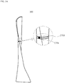
- FIG. 3A is a view illustrating one example measuring the flutter of the turbine blade by placing a sensor on the turbine blade in accordance with an embodiment of the present disclosure.
- the sensor module 210 placed on the turbine blade 300 can include a first sensor 210a.
- the first sensor 210a can be provided to the point where one end and the other end of an optical fiber 210d meet, and the first sensor 210a can transmit a signal in one direction of the optical fiber 210d.
- the optical fiber 210d may be in contact with the turbine blade 300 along the blade direction of the turbine blade 300, and the blade direction refers to the direction that circumferentially wraps around the outer surface of the turbine blade 300.
- the signal outputted by the first sensor 210a can be again delivered to the first sensor 210a through the optical fiber 210d. Accordingly, the sensor module 210 can sense the wavelength of the signal on the flutter of the turbine blade 300 through the signal received by the first sensor 210a. Furthermore, the sensor module 210 can sense the time until the first sensor 210a again receives the signal transmitted by the first sensor 210a.
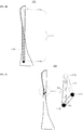
- FIG. 3B is a view illustrating another example measuring the flutter of the turbine blade by placing the sensor on the turbine blade in accordance with an embodiment of the present disclosure.
- the same description as the control method of the control unit in FIG. 3A will be omitted for simplicity of explanation.
- the sensors of the sensor module 210 placed on the turbine blade 300 are provided to one end and the other end of the optical fiber 210d, respectively, and the optical fiber 210d can be provided along the length direction thereof.
- the length direction refers to the direction in which the turbine blade 300 is extended not in the blade direction thereof, but in the radial direction from a turbine rotor.
- the sensors of the sensor module 210 placed on the turbine blade 300 can include the first sensor 210a provided to one end of the optical fiber 210d and a second sensor 210b provided to the other end of the optical fiber 210d.
- the signal transmitted by the first sensor 210a can be delivered to the second sensor 210b through the optical fiber 210d, and the second sensor 210b can sense the wavelength of the signal on the flutter of the turbine blade 300. Furthermore, the sensor module 210 can sense the time until the second sensor 210b receives the signal transmitted by the first sensor 210a.
- FIG. 3C is a view illustrating yet another example measuring the flutter of the turbine blade by placing the sensor on the turbine blade in accordance with an embodiment of the present disclosure.
- the sensor of the sensor module 210 placed on the turbine blade 300 can be provided in plural along the blade direction of the turbine blade 300, and the optical fiber can be provided in plural along the blade direction of the turbine blade 300.
- the sensor and the optical fiber can be provided by three, respectively.
- the first sensor 210a can transmit the signal to the second sensor 210b
- the second sensor 210b can transmit the signal to a third sensor 210c
- the third sensor 210c can transmit the signal to the first sensor 210a.
- the first optical fiber 210d can connect the first sensor 210a and the second sensor 210b
- a second optical fiber 210e can connect the second sensor 210b and the third sensor 210c
- a third optical fiber 210f can connect the third sensor 210c and the first sensor 210a.
- the sensor module 210 can sense the wavelength of the signal on the flutter of the turbine blade 300 using the signal transmitted/received by the sensors 210a, 210b, and 210c, and the sensor module 210 can sense the transmission/reception time of the signal transmitted between the sensors 210a, 210b, and 210c to measure the flutter for each section of the outer surface of the turbine blade 300.
- the sensor module 210 can provide the sensed wavelength of the signal on the flutter of the turbine blade 300 and the sensed transmission/reception time to the interface 220.
- FIG. 4 is a view illustrating the magnetic field communication in accordance with an embodiment of the present disclosure.
- the sensor module 210 can sense the wavelength of the signal on the flutter of the turbine blade 300 and the time transmitted/received from the sensor 210a.
- the interface 220 can convert the wavelength of the signal on the flutter of the turbine blade 300 sensed in the sensor 210a and the time transmitted/received from the sensor 210a into the magnetic field signal. Furthermore, the interface 220 can transmit the converted magnetic field signal to the magnetic field reception unit 120 through the magnetic field.
- the interface 220 can include a separate passive element for impedance matching with the adaptor 100.
- the antenna 110 can receive the magnetic field signal transmitted from the interface 220 to deliver it to the magnetic field reception unit 120.
- the interface 220 and the magnetic field reception unit 120 may be set to have the same resonance frequency, and the distance and the location between the interface 220 and the magnetic field reception unit 120 may be set to be placed at a specific distance or a specific location to transmit the maximum power. That is, it is possible to enhance the reception performance of the magnetic field communication through the impedance matching between the adaptor 100 and the sensor unit 200.
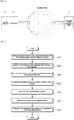
- FIG. 5 is a flowchart illustrating a method of the magnetic field communication system for measuring the flutter of the turbine blade in accordance with an embodiment of the present disclosure.
- the sensor module 210 can be placed on the outer surface of the turbine blade 300 to sense the wavelength of the signal on the flutter of the turbine blade 300 and the time transmitted/received from the sensor S610.
- the interface 220 can convert the wavelength sensed in the sensor module 210 and the time transmitted/received from the sensor 210a of the sensor module 210 into the magnetic field signal, and transmit the converted magnetic field signal S620.
- the signal conversion unit 222 can convert the sense signal sensed by the sensor module 210 into the magnetic field signal
- the communication unit 224 can transmit the converted magnetic field signal to the outside of the turbine blade 300.
- the magnetic field reception unit 120 can receive the magnetic field signal transmitted from the interface 220 S630.
- the magnetic field reception unit 120 can provide the received magnetic field signal to the control unit 150.
- the power source unit 130 can receive the magnetic field signal from the control unit 150 to generate the power source S640. If the power source unit 130 is not charged, the control unit 150 can supply the magnetic field signal to the power source unit 130. And, the power source unit 130 can generate the power source using the received magnetic field signal, and store the generated power source. Herein, the power source unit 130 can store the current generated by the electromagnetic induction phenomenon caused by the magnetic field, and the generated current can be stored in the capacitor.
- control unit 150 can analyze the magnetic field signal using an electrical signal stored in the power source unit 130 as the power source S650.
- control unit 150 can no longer supply the magnetic field signal to the power source unit 130, and analyze the received magnetic field signal.
- control unit 150 can supply the magnetic field signal so that the amount of the power source stored in the power source unit 130 is equal to or greater than the first amount.
- control unit 150 can analyze the magnetic field signal to determine the degree of the flutter of the turbine blade 300 S660.
- FIG. 6 is a flowchart illustrating a method of measuring the flutter of the turbine blade in accordance with an embodiment of the present disclosure. The S660 will be described in detail with reference to FIG. 6 .
- the wavelength of the signal on the flutter of the turbine blade 300 and the time when the signal is transmitted/received from the sensor 210a of the sensor module 210 can be stored S661.
- the magnetic field signal received from the interface 220 can be analyzed to sense the wavelength of the signal on the flutter of the turbine blade 300 and the time when the signal is transmitted/received from the sensor 210a of the sensor module 210 S662.
- the flutter of the turbine blade 300 can be measured in the normal range within an error range to perform the procedure of S660.
- the wavelength of the signal on the flutter of the turbine blade 300 and the time transmitted/received from the sensor 210a of the sensor module 210, which are pre-stored, and the wavelength of the signal on the flutter of the turbine blade 300 and the time transmitted/received from the sensor 210a of the sensor module 210, which are sensed it can be determined S664 that the flutter of the turbine blade 300 is in the abnormal range if an error range is exceeded, and the magnetic field signal can be transmitted to a separate communication device S670.
- the separate communication device can be the sensor unit 200, and can be other devices other than the sensor unit 200.
- the magnetic field communication system in accordance with an embodiment of the present disclosure, can transmit/receive the magnetic field to voluntarily generate the power source, thus measuring the flutter of the turbine blade without replacing the battery of the sensor module, and simplifying the configuration of the communication system because a separate battery is not required.
Landscapes
- Engineering & Computer Science (AREA)
- Physics & Mathematics (AREA)
- General Physics & Mathematics (AREA)
- Computer Networks & Wireless Communication (AREA)
- Signal Processing (AREA)
- Mechanical Engineering (AREA)
- General Engineering & Computer Science (AREA)
- Chemical & Material Sciences (AREA)
- Health & Medical Sciences (AREA)
- Electrochemistry (AREA)
- Chemical Kinetics & Catalysis (AREA)
- Life Sciences & Earth Sciences (AREA)
- Analytical Chemistry (AREA)
- Biochemistry (AREA)
- General Health & Medical Sciences (AREA)
- Immunology (AREA)
- Pathology (AREA)
- Arrangements For Transmission Of Measured Signals (AREA)
- Length Measuring Devices By Optical Means (AREA)
- Power Engineering (AREA)
Abstract
Description
- The present disclosure relates to a magnetic field communication system and a method for measuring flutter of a turbine blade, and more particularly, to a magnetic field communication system and a method for measuring flutter of a turbine blade that communicates a signal sensing the state of the turbine blade using a magnetic field, and converting a magnetic field signal into a power source to analyze the state of the turbine blade.
- If a rotation speed of a turbine increases when the turbine operates, the phenomenon that the turbine blade is bent or twisted by air pressure is caused. The phenomenon is defined as flutter. The flutter causes a decrease in the output of an engine. Accordingly, a system and a method capable of reducing damage of the turbine by sensing the flutter are required.
- Now, in order to measure the flutter of the turbine blade, there is a method of assuming the state of the turbine blade by sensing the vibration of the turbine blade, and the method has the problem in that an error may be caused depending upon the location of the turbine blade where the vibration is sensed. Furthermore, in order to constantly sense the state of turbine blade, it is inconvenient to periodically replace a battery of a sensor module.
- (Patent Document 1) Korean Patent Laid-Open Publication No.
10-2015-0060937 - The present disclosure is proposed for resolving the above problem, and the object of the present disclosure is to provide a magnetic field communication system and a method capable of measuring flutter of a turbine blade placed inside a casing of a turbine.
- Furthermore, the object of the present disclosure is to provide the magnetic field communication system and the method for measuring the flutter of the turbine blade capable of measuring the flutter of the turbine blade without replacing the battery of the sensor module by voluntarily generating a power source using a magnetic field.
- Other than the objects of the present disclosure described above, it is obvious to those skilled in the art to which the present disclosure pertains that other features and advantages of the present disclosure will be described hereinafter, or can be understood from such a technology and description.
- A magnetic field communication system for measuring flutter of a turbine blade in accordance with an embodiment of the present disclosure for achieving the objects described above includes a sensor module placed on an outer surface of the turbine blade to sense a signal on the flutter of the turbine blade; an interface converting the signal on the flutter sensed by the sensor module into a magnetic field signal to transmit it to the outside of a casing surrounding the turbine blade; and an adaptor receiving the magnetic field signal to generate a power source of the system, and analyzing the magnetic field signal to determine the degree of the flutter of the turbine blade.
- Furthermore, the sensor module includes an optical fiber placed on the outer surface of the turbine blade; and at least one sensor.
- Furthermore, the optical fiber contacts along the blade direction of the turbine blade, the sensor is provided to the point where one end and the other end of the optical fiber meet, and the sensor senses the change of the wavelength of a signal and the time when the signal transmitted from the sensor again reaches the sensor by the optical fiber by transmitting the signal in one direction of the optical fiber and receiving the transmitted signal.
- Furthermore, the sensor is provided in plural along the blade direction of the turbine blade, and the sensors measure the flutter for each section of the outer surface of the turbine blade.
- Furthermore, the optical fiber is provided along the length direction in which the turbine blade is extended from a turbine rotor, and the sensor is provided in plural to one end and the other end of the optical fiber, respectively.
- Furthermore, the sensors include a first sensor provided to one end of the optical fiber, and a second sensor provided to the other end of the optical fiber, and the second sensor receives the signal transmitted by the first sensor to measure the change of the wavelength of the signal and the reach time of the signal.
- Furthermore, the interface is placed on the outer surface of the turbine blade.
- Furthermore, the adaptor includes a magnetic field reception unit receiving the magnetic field signal; a control unit analyzing the magnetic field signal to measure the flutter of the turbine blade; and a power source unit generating a power source using the magnetic field signal, and storing the power source.
- Furthermore, if the power source unit is not charged, the control unit uses the magnetic field signal to supply it to the power source unit to generate the power source.
- Furthermore, if the amount of the power source charged in the power source unit is equal to or greater than a first amount, the control unit uses the magnetic field signal to measure the flutter of the turbine blade, the first amount being the amount that the charging of the power source unit is completed.
- Furthermore, if the amount of the power source stored in the power source unit after the charging of the power source unit is completed is reduced to be equal to or smaller than a second amount, the control unit uses the received magnetic field signal to charge the power source unit.
- Furthermore, the control unit analyzes the wavelength of the signal on the flutter measured by the sensor module by analyzing the magnetic field signal to compare it with a pre-stored wavelength.
- Furthermore, as a result of comparing the wavelength of the signal on the flutter with the pre-stored wavelength, the control unit determines the flutter of the turbine blade in the normal range within an error range, and as a result of comparing the wavelength of the signal on the flutter with the pre-stored wavelength, determines the flutter of the turbine blade in the abnormal range if the error range is exceeded.
- Furthermore, the control unit analyzes a transmission/reception time of the signal on the flutter measured by the sensor module by analyzing the magnetic field signal to compare it with a pre-stored transmission/reception time.
- Furthermore, as a result of comparing the transmission/reception time of the signal on the flutter with the pre-stored transmission/reception time, the control unit determines the flutter range of the turbine blade in the normal range within an error range, and as a result of comparing the transmission/reception time of the signal on the flutter with the pre-stored transmission/reception time, determines the flutter range of the turbine blade in the abnormal range if the error range is exceeded.
- Furthermore, the present disclosure includes a sensor module, which is placed on an outer surface of a turbine blade, sensing the wavelength and the transmission/reception time of a signal on the flutter of the turbine blade; converting the sensed wavelength and the sensed transmission/reception time into a magnetic field signal to transmit it to the outside of a casing surrounding the turbine blade; and analyzing the magnetic field signal, which is received by the adaptor to generate a power source of the system, to determine the flutter of the turbine blade.
- Furthermore, the sensor module includes an optical fiber placed on the outer surface of the turbine blade and at least one sensor, and the adaptor includes a magnetic field reception unit receiving the magnetic field signal; a control unit analyzing the magnetic field signal to measure the flutter of the turbine blade; and a power source unit generating the power source using the magnetic field signal and storing the power source.
- Furthermore, the determining of the flutter of the turbine blade includes the power source unit generating the power source using the magnetic field signal, and the control unit analyzing the received magnetic field signal to determine the flutter of the turbine blade if the power source unit is charged to be equal to or greater than a first amount, the first amount being the amount that the charging of the power source unit is completed.
- Furthermore, in the determining of the flutter of the turbine blade, the control unit uses the received magnetic field signal until the amount of the power source charged in the power source unit becomes equal to or greater than the first amount to generate the power source.
- Furthermore, in the determining of the flutter of the turbine blade, if the amount of the power source stored in the power source unit that is equal to or greater than the first amount is reduced to be equal to or smaller than a second amount, the control unit further includes supplying the magnetic field signal to the power source unit so that the amount of the power source of the power source unit again becomes equal to or greater than the first amount.
- The magnetic field communication system for measuring the flutter of the turbine blade in accordance with an embodiment of the present disclosure can reduce damage of the turbine by measuring the flutter of the turbine blade placed inside the casing of the turbine. Furthermore, it is possible to transmit/receive the magnetic field to voluntarily generate the power source, thus measuring the flutter of the turbine blade without replacing the battery of the sensor module, and simplifying the configuration of the communication system because a separate battery is not required.
- Other than the above, other features and advantages of the present disclosure can be newly identified through embodiments of the present disclosure.
-
-
FIG. 1 is a view schematically illustrating a magnetic field communication system for measuring flutter of a turbine blade in accordance with an embodiment of the present disclosure. -
FIG. 2 is a view schematically illustrating the configuration of an interface in accordance with an embodiment of the present disclosure. -
FIG. 3A is a view illustrating one example measuring the flutter of the turbine blade by placing a sensor on the turbine blade in accordance with an embodiment of the present disclosure. -
FIG. 3B is a view illustrating another example measuring the flutter of the turbine blade by placing the sensor on the turbine blade in accordance with an embodiment of the present disclosure. -
FIG. 3C is a view illustrating yet another example measuring the flutter of the turbine blade by placing the sensor on the turbine blade in accordance with an embodiment of the present disclosure. -
FIG. 4 is a view illustrating the magnetic field communication in accordance with an embodiment of the present disclosure. -
FIG. 5 is a flowchart illustrating a method of the magnetic field communication system for measuring the flutter of the turbine blade in accordance with an embodiment of the present disclosure. -
FIG. 6 is a flowchart illustrating a method of measuring the flutter of the turbine blade in accordance with an embodiment of the present disclosure. - Hereinafter, exemplary embodiments of the present disclosure will be described in detail with reference to the accompanying drawings so that those skilled in the art to which the present disclosure pertains may easily practice the present disclosure. The present disclosure may be implemented in various different forms, and is not limited to the exemplary embodiments described herein.
- Descriptions of irrelevant components are omitted so as to clearly describe the exemplary embodiments of the present disclosure, and throughout this specification, the same or like elements are denoted by the same reference numerals.
- Throughout this specification, it will be understood that when an element is referred to as being "connected" to another element, it can be "directly connected" to the other element or "electrically connected" to the other element with other elements interposed therebetween. It will be further understood that when an element is referred to as "comprises" another element, the element is intended not to exclude one or more other elements, but to further include one or more other elements, unless the context clearly indicates otherwise.
- When it is described that any one part is "on" the other part, it may mean that the part is directly on the other part or any other part is interposed therebetween. On the contrary, when it is described that any one part is "directly on" the other part, there is no other part interposed therebetween.
- The terminology used herein is for the purpose of describing particular embodiments only and is not intended to limit the present disclosure. The singular forms used herein are intended to include the plural forms as well, unless the context clearly indicates otherwise. It will be further understood that the terms "comprises" and/or "comprising," or "includes" and/or "including" used in this specification, specify the presence of stated features, regions, integers, steps, operations, elements, and/or components, but do not preclude the presence or addition of other features, regions, integers, steps, operations, elements, and/or components.
- Terms "below", "above", and the like indicating a relative space may be used to more easily describe a relationship between one part illustrated in the drawings with another part. These terms are intended to include other meanings or operations of a device that is being used, in addition to meanings intended in the drawings. For example, when the device in the drawing is inverted, any parts described as being "below" other parts may be described as being "above" the other parts. Therefore, the exemplary term "below" includes both of an upper direction and a lower direction. The device may rotate by 90° or other angles, and the terms indicating a relative space are interpreted according thereto.
- Unless otherwise defined, all terms (including technical and scientific terms) used herein have the same meaning as commonly understood by one of ordinary skill in the art to which the present disclosure pertains. The terms defined in commonly used dictionaries, should be additionally interpreted as having a meaning that is consistent with the context of the relevant art and the present disclosure, and will not be interpreted in an idealized or overly formal sense unless expressly so defined herein.
-
FIG. 1 is a view schematically illustrating a magnetic field communication system for measuring flutter of a turbine blade in accordance with an embodiment of the present disclosure, andFIG. 2 is a view schematically illustrating the configuration of an interface in accordance with an embodiment of the present disclosure. - Referring to
FIGS. 1 and 2 , a magnetic field communication system for measuring flutter of a turbine blade in accordance with an embodiment of the present disclosure can include asensor unit 200 and anadaptor 100. - The
sensor unit 200 can include asensor module 210 and aninterface 220. Thesensor module 210 can be placed on an outer surface of the turbine blade, and include an optical fiber placed on the outer surface of the turbine blade and at least one sensor. The detailed description of thesensor module 210 will be described later. - The
interface 220 can be placed on the outer surface of the turbine blade to receive the wavelength of a signal on the flutter of the turbine blade sensed by thesensor module 210 and the transmission/reception time of the signal. Theinterface 220 can transmit information including the wavelength of the signal on the flutter of the turbine blade and the transmission/reception time of the signal on the flutter of the turbine blade, which are received, to the outside of a casing surrounding the turbine blade. As one example, theinterface 220 can be placed on the outer surface of the turbine blade as a separate configuration from thesensor module 210. As another example, theinterface 220 can be one configuration of thesensor module 210. - The
interface 220 can include asignal conversion unit 222 and acommunication unit 224. Thecommunication unit 224 can receive from thesensor module 210 the information including the wavelength of the signal on the flutter of theturbine blade 300 and the transmission/reception time of the signal on the flutter of the turbine blade. Thesignal conversion unit 222 can convert the signal received by thecommunication unit 224 into a magnetic field signal. Furthermore, thecommunication unit 224 can transmit the converted magnetic field signal to the outside of the casing surrounding the turbine blade. - The
adaptor 100 can receive the magnetic field signal to generate the power source of the system, and analyze the wavelength of the signal on the flutter of the turbine blade and the transmission/reception time of the signal on the flutter of the turbine blade by analyzing the magnetic field signal to determine the occurrence degree of the flutter of the turbine blade. - The
adaptor 100 can include anantenna 110, a magneticfield reception unit 120, apower source unit 130, a magneticfield transmission unit 140, and acontrol unit 150. - The
antenna 110 can receive the magnetic field signal transmitted from theinterface 220 to deliver it to the magneticfield reception unit 120. Herein, in the magnetic field communication between theinterface 220 and theadaptor 100, theinterface 220 and theadaptor 100 may be set to have the same resonance frequency to transmit the maximum power. Furthermore, the distance and the location of theinterface 220 and theadaptor 100 may be set to be placed at a specific distance or a specific location to transmit the maximum power. - The magnetic
field reception unit 120 can receive the magnetic field signal transmitted from theinterface 220 through theantenna 110, and provide the received magnet field signal to thecontrol unit 150. - The
power source unit 130 can generate the power source using the magnetic field signal provided from thecontrol unit 150, and store the generated power source. Specifically, thepower source unit 130 can include a coil that can convert the applied magnetic field into current, and a capacitor that can store the generated current. Thepower source unit 130 stores the current generated by the electromagnetic induction phenomenon caused by the magnetic field in the capacitor. If the current is no longer supplied to the capacitor, thepower source unit 130 can use the current stored in the capacitor as the power source. Accordingly, if the magnetic field signal is supplied from thecontrol unit 150, thepower source unit 130 can store the current generated by the magnetic field signal in the capacitor, and if the current is no longer supplied to the capacitor because the magnetic field signal is not supplied from thecontrol unit 150, thepower source unit 130 can use the current stored in the capacitor as the power source. - The
control unit 150 can supply the magnetic field signal receiving in the magneticfield reception unit 120 to thepower source unit 130, and analyze the received magnetic field signal. Specifically, thecontrol unit 150 can supply the magnetic field signal based upon the amount of the power source stored in thepower source unit 130. Herein, thecontrol unit 150 can monitor thepower source unit 130 to determine the amount of the power source stored in thepower source unit 130. - As one example, if the
power source unit 130 is not charged, thecontrol unit 150 can supply the magnetic field signal to thepower source unit 130 until the amount of thepower source unit 130 becomes equal to or greater than a first amount. Thecontrol unit 150 cannot analyze the magnetic field signal until the amount of thepower source unit 130 becomes equal to or greater than the first amount. In this case, thepower source unit 130 can generate the power source using the magnetic field signal supplied from thecontrol unit 150, and store the generated power source. For example, the first amount can be the amount that the charging of thepower source unit 130 is completed, or even if the charging of thepower source unit 130 is not completed, can be the amount of the degree that can analyze the magnetic field signal. - As one example, if the amount of the power source charged in the
power source unit 130 is equal to or greater than the first amount, thecontrol unit 150 can no longer supply the magnetic field signal to thepower source unit 130, and analyze the magnetic field signal to determine the degree of the flutter of the turbine blade. In this case, thecontrol unit 150 can receive the power source from thepower source unit 130 to analyze the degree of the flutter of the turbine blade. - As one example, if the power source stored in the power source unit is reduced to be equal to or smaller than a second amount after the charging of the
power source unit 130 is completed, thecontrol unit 150 can again supply the magnetic field signal to thepower source unit 130. In this case, thecontrol unit 150 cannot use the magnetic field signal in order to analyze the degree of the flutter of the turbine blade, and control to supply all of the magnetic field signals to thepower source unit 130 to generate the power source. For example, the second amount can be the amount that the power source stored in thepower source unit 130 are all discharged, or even if the power source stored in thepower source unit 130 is not all discharged, can be the amount that is not enough analyze the magnetic field signal. - Herein, the
control unit 150 can supply the magnetic field signal so that the amount of the power source stored in thepower source unit 130 is equal to or greater than the first amount, and if the amount of the power source stored in thepower source unit 130 is equal to or greater than the first amount, it can analyze the magnetic field signal receiving in the magneticfield reception unit 120 using the stored power source. Furthermore, if the amount of the power source stored in thepower source unit 130 is reduced to be equal to or smaller than the second amount, thecontrol unit 150 can again supply the magnetic field signal receiving in the magneticfield reception unit 120 to thepower source unit 130. That is, thecontrol unit 150 can measure the flutter of the turbine blade without a separate power source device. - Furthermore, the
control unit 150 can analyze the magnetic field signal to determine the degree of the flutter of the turbine blade. Thecontrol unit 150 can analyze the magnetic field signal to sense the wavelength of the signal on the flutter of the turbine blade, and compare it with a pre-stored wavelength. As a result of comparing the wavelength of the signal on the flutter of the turbine blade with the pre-stored wavelength, thecontrol unit 150 can measure the flutter of the turbine blade in the normal range within the error range. Furthermore, as a result of comparing the wavelength of the signal on the flutter of the turbine blade with the pre-stored wavelength, thecontrol unit 150 can measure the flutter of the turbine blade in the abnormal range if the error range is exceeded. - Furthermore, the
control unit 150 can analyze the magnetic field signal to compare the transmission/reception time sensed by thesensor module 210 with a pre-stored transmission/reception time. As a result of comparing the transmission/reception time sensed by thesensor module 210 with the pre-stored transmission/reception time, thecontrol unit 150 can measure the flutter of the turbine blade in the normal range within the error range. Furthermore, as a result of comparing the transmission/reception time sensed by thesensor module 210 with the pre-stored transmission/reception time, thecontrol unit 150 can measure the flutter of the turbine blade in the abnormal range if the error range is exceeded. - If it is determined that the flutter of the turbine blade is in the abnormal range, the
control unit 150 can provide the analyzed result of the magnetic field signal to the magneticfield transmission unit 140. - The magnetic
field transmission unit 140 can provide the magnetic field signal to a separate communication device. In this case, the magneticfield transmission unit 140 can use the magnetic field to transmit it to the separate communication device, and the separate communication device can be asensor unit 200 and other devices other than thesensor unit 200. - The magnetic field communication system for measuring the flutter of the turbine blade in accordance with an embodiment of the present disclosure can adopt a communication method using the magnetic field, and thus the communication between the inside of the casing of the turbine blade and the outside thereof, which is difficult to communicate, can be made possible.
- Furthermore, since the magnetic field communication system for measuring the flutter of the turbine blade in accordance with an embodiment of the present disclosure does not require a separate power source device, the communication system with the simplified configuration can be implemented. As the configuration for measuring the flutter of the turbine blade becomes simplified, the
adaptor 100 that is one component of the magnetic field communication system can be provided in the region having a narrow space. - Furthermore, the magnetic field communication system for measuring the flutter of the turbine blade in accordance with an embodiment of the present disclosure can be applied to various types of turbines, such as a wind turbine, a steam turbine, a gas turbine, and a vapor turbine.
-
FIG. 3A is a view illustrating one example measuring the flutter of the turbine blade by placing a sensor on the turbine blade in accordance with an embodiment of the present disclosure. - Referring to
FIGS. 1 to 3A , thesensor module 210 placed on theturbine blade 300 can include afirst sensor 210a. Thefirst sensor 210a can be provided to the point where one end and the other end of anoptical fiber 210d meet, and thefirst sensor 210a can transmit a signal in one direction of theoptical fiber 210d. Theoptical fiber 210d may be in contact with theturbine blade 300 along the blade direction of theturbine blade 300, and the blade direction refers to the direction that circumferentially wraps around the outer surface of theturbine blade 300. - The signal outputted by the
first sensor 210a can be again delivered to thefirst sensor 210a through theoptical fiber 210d. Accordingly, thesensor module 210 can sense the wavelength of the signal on the flutter of theturbine blade 300 through the signal received by thefirst sensor 210a. Furthermore, thesensor module 210 can sense the time until thefirst sensor 210a again receives the signal transmitted by thefirst sensor 210a. -
FIG. 3B is a view illustrating another example measuring the flutter of the turbine blade by placing the sensor on the turbine blade in accordance with an embodiment of the present disclosure. InFIG. 3B , the same description as the control method of the control unit inFIG. 3A will be omitted for simplicity of explanation. - Referring to
FIG. 3B , the sensors of thesensor module 210 placed on theturbine blade 300 are provided to one end and the other end of theoptical fiber 210d, respectively, and theoptical fiber 210d can be provided along the length direction thereof. The length direction refers to the direction in which theturbine blade 300 is extended not in the blade direction thereof, but in the radial direction from a turbine rotor. - The sensors of the
sensor module 210 placed on theturbine blade 300 can include thefirst sensor 210a provided to one end of theoptical fiber 210d and asecond sensor 210b provided to the other end of theoptical fiber 210d. - The signal transmitted by the
first sensor 210a can be delivered to thesecond sensor 210b through theoptical fiber 210d, and thesecond sensor 210b can sense the wavelength of the signal on the flutter of theturbine blade 300. Furthermore, thesensor module 210 can sense the time until thesecond sensor 210b receives the signal transmitted by thefirst sensor 210a. -
FIG. 3C is a view illustrating yet another example measuring the flutter of the turbine blade by placing the sensor on the turbine blade in accordance with an embodiment of the present disclosure. - Referring to
FIG. 3C , the sensor of thesensor module 210 placed on theturbine blade 300 can be provided in plural along the blade direction of theturbine blade 300, and the optical fiber can be provided in plural along the blade direction of theturbine blade 300. - As one example, the sensor and the optical fiber can be provided by three, respectively. The
first sensor 210a can transmit the signal to thesecond sensor 210b, thesecond sensor 210b can transmit the signal to athird sensor 210c, and thethird sensor 210c can transmit the signal to thefirst sensor 210a. - The first
optical fiber 210d can connect thefirst sensor 210a and thesecond sensor 210b, a secondoptical fiber 210e can connect thesecond sensor 210b and thethird sensor 210c, and a thirdoptical fiber 210f can connect thethird sensor 210c and thefirst sensor 210a. - The
sensor module 210 can sense the wavelength of the signal on the flutter of theturbine blade 300 using the signal transmitted/received by thesensors sensor module 210 can sense the transmission/reception time of the signal transmitted between thesensors turbine blade 300. - The
sensor module 210 can provide the sensed wavelength of the signal on the flutter of theturbine blade 300 and the sensed transmission/reception time to theinterface 220. -
FIG. 4 is a view illustrating the magnetic field communication in accordance with an embodiment of the present disclosure. - Referring to
FIG. 4 , thesensor module 210 can sense the wavelength of the signal on the flutter of theturbine blade 300 and the time transmitted/received from thesensor 210a. - The
interface 220 can convert the wavelength of the signal on the flutter of theturbine blade 300 sensed in thesensor 210a and the time transmitted/received from thesensor 210a into the magnetic field signal. Furthermore, theinterface 220 can transmit the converted magnetic field signal to the magneticfield reception unit 120 through the magnetic field. In this case, theinterface 220 can include a separate passive element for impedance matching with theadaptor 100. Herein, theantenna 110 can receive the magnetic field signal transmitted from theinterface 220 to deliver it to the magneticfield reception unit 120. - In the magnetic field communication between the
interface 220 and the magneticfield reception unit 120, theinterface 220 and the magneticfield reception unit 120 may be set to have the same resonance frequency, and the distance and the location between theinterface 220 and the magneticfield reception unit 120 may be set to be placed at a specific distance or a specific location to transmit the maximum power. That is, it is possible to enhance the reception performance of the magnetic field communication through the impedance matching between theadaptor 100 and thesensor unit 200. -
FIG. 5 is a flowchart illustrating a method of the magnetic field communication system for measuring the flutter of the turbine blade in accordance with an embodiment of the present disclosure. - Referring to
FIGS. 1 to 3C and5 , thesensor module 210 can be placed on the outer surface of theturbine blade 300 to sense the wavelength of the signal on the flutter of theturbine blade 300 and the time transmitted/received from the sensor S610. - Next, the
interface 220 can convert the wavelength sensed in thesensor module 210 and the time transmitted/received from thesensor 210a of thesensor module 210 into the magnetic field signal, and transmit the converted magnetic field signal S620. Specifically, thesignal conversion unit 222 can convert the sense signal sensed by thesensor module 210 into the magnetic field signal, and thecommunication unit 224 can transmit the converted magnetic field signal to the outside of theturbine blade 300. - Next, the magnetic
field reception unit 120 can receive the magnetic field signal transmitted from theinterface 220 S630. The magneticfield reception unit 120 can provide the received magnetic field signal to thecontrol unit 150. - Next, the
power source unit 130 can receive the magnetic field signal from thecontrol unit 150 to generate the power source S640. If thepower source unit 130 is not charged, thecontrol unit 150 can supply the magnetic field signal to thepower source unit 130. And, thepower source unit 130 can generate the power source using the received magnetic field signal, and store the generated power source. Herein, thepower source unit 130 can store the current generated by the electromagnetic induction phenomenon caused by the magnetic field, and the generated current can be stored in the capacitor. - Next, the
control unit 150 can analyze the magnetic field signal using an electrical signal stored in thepower source unit 130 as the power source S650. - If the amount of the power source stored in the
power source unit 130 is equal to or greater than the first amount, thecontrol unit 150 can no longer supply the magnetic field signal to thepower source unit 130, and analyze the received magnetic field signal. - If the amount of the power source stored in the
power source unit 130 that is equal to or greater than the first amount is reduced to be equal to or smaller than the second amount, thecontrol unit 150 can supply the magnetic field signal so that the amount of the power source stored in thepower source unit 130 is equal to or greater than the first amount. - Next, the
control unit 150 can analyze the magnetic field signal to determine the degree of the flutter of theturbine blade 300 S660. -
FIG. 6 is a flowchart illustrating a method of measuring the flutter of the turbine blade in accordance with an embodiment of the present disclosure. The S660 will be described in detail with reference toFIG. 6 . - Referring to
FIGS. 1 to 3C and6 , the wavelength of the signal on the flutter of theturbine blade 300 and the time when the signal is transmitted/received from thesensor 210a of thesensor module 210 can be stored S661. Next, the magnetic field signal received from theinterface 220 can be analyzed to sense the wavelength of the signal on the flutter of theturbine blade 300 and the time when the signal is transmitted/received from thesensor 210a of thesensor module 210 S662. - Next, by comparing the wavelength of the signal on the flutter of the
turbine blade 300 and the time when the signal is transmitted/received from thesensor 210a of thesensor module 210, which are pre-stored, with the wavelength of the signal on the flutter of theturbine blade 300 and the time when the signal is transmitted/received from thesensor 210a of thesensor module 210, which are sensed, an error can be measured S663. - Next, in the comparing of the S663, as a result of comparing the wavelength of the signal on the flutter of the
turbine blade 300 and the time transmitted/received from thesensor 210a of thesensor module 210, which are pre-stored, with the wavelength of the signal on the flutter of theturbine blade 300 and the time transmitted/received from thesensor 210a of thesensor module 210, which are sensed, the flutter of theturbine blade 300 can be measured in the normal range within an error range to perform the procedure of S660. - Meanwhile, as a result of comparing the wavelength of the signal on the flutter of the
turbine blade 300 and the time transmitted/received from thesensor 210a of thesensor module 210, which are pre-stored, and the wavelength of the signal on the flutter of theturbine blade 300 and the time transmitted/received from thesensor 210a of thesensor module 210, which are sensed, it can be determined S664 that the flutter of theturbine blade 300 is in the abnormal range if an error range is exceeded, and the magnetic field signal can be transmitted to a separate communication device S670. The separate communication device can be thesensor unit 200, and can be other devices other than thesensor unit 200. - In accordance with an embodiment of the present disclosure, it is possible to measure the flutter of the turbine blade that is difficult to sense to sense damage of the turbine in advance, thus reducing the severe damage of the turbine. Furthermore, the magnetic field communication system in accordance with an embodiment of the present disclosure can transmit/receive the magnetic field to voluntarily generate the power source, thus measuring the flutter of the turbine blade without replacing the battery of the sensor module, and simplifying the configuration of the communication system because a separate battery is not required.
- Those skilled in the art to which the present disclosure pertains should be understood that the present disclosure may be implemented in other various forms without departing from the technical spirit or essential characteristics of the present disclosure, so the aforementioned embodiments should not be construed as being limitative, but should be construed as being only illustrative from all aspects. The scope of the present disclosure is disclosed in the appended claims rather than the detailed description, and it should be understood that all modifications or variations derived from the meanings and scope of the present disclosure and equivalents thereof are included in the scope of the appended claims.
Claims (15)
- A magnetic field communication system for measuring flutter of a turbine blade, comprising:a sensor module placed on an outer surface of the turbine blade to sense a signal on the flutter of the turbine blade;an interface converting the signal on the flutter sensed by the sensor module into a magnetic field signal to transmit it to the outside of a casing surrounding the turbine blade; andan adaptor receiving the magnetic field signal and analyzing the magnetic field signal to determine the degree of the flutter of the turbine blade.
- The magnetic field communication system for measuring the flutter of the turbine blade of claim 1, wherein the sensor module comprising:an optical fiber placed on the outer surface of the turbine blade; andat least one sensor connected with the optical fiber.
- The magnetic field communication system for measuring the flutter of the turbine blade of claim 2,
wherein the optical fiber contacts along the blade direction of the turbine blade,
wherein the sensor is provided to the point where one end and the other end of the optical fiber meet, and
wherein the sensor senses the change of the wavelength of a signal and the time when the signal transmitted from the sensor again reaches the sensor by the optical fiber by transmitting the signal in one direction of the optical fiber and receiving the transmitted signal. - The magnetic field communication system for measuring the flutter of the turbine blade of claim 2 or 3, wherein the sensor is provided in plural along the blade direction of the turbine blade, and the sensors measure the flutter for each section of the outer surface of the turbine blade.
- The magnetic field communication system for measuring the flutter of the turbine blade of claim 2, 3 or 4,
wherein the optical fiber is provided along the length direction in which the turbine blade is extended from a turbine rotor, and
wherein the sensor is provided in plural to one end and the other end of the optical fiber, respectively. - The magnetic field communication system for measuring the flutter of the turbine blade of claim 2, 3, 4 or 5,
wherein the sensors comprise a first sensor provided to one end of the optical fiber, and a second sensor provided to the other end of the optical fiber, and
wherein the second sensor receives the signal transmitted by the first sensor to measure the change of the wavelength of the signal and the reach time of the signal. - The magnetic field communication system for measuring the flutter of the turbine blade as claimed in any one of the preceding claims, wherein the interface is placed on the outer surface of the turbine blade.
- The magnetic field communication system for measuring the flutter of the turbine blade as claimed in any one of the preceding claims, wherein the adaptor comprising:a magnetic field reception unit receiving the magnetic field signal;a control unit analyzing the magnetic field signal to measure the flutter of the turbine blade.
- The magnetic field communication system for measuring the flutter of the turbine blade of claim 8,
a power source unit generating a power source using the magnetic field signal and storing the power source, wherein if the amount of the power source charged in the power source unit is equal to or greater than a first amount, the control unit is configured to use the magnetic field signal to measure the flutter of the turbine blade, the first amount being the amount that the charging of the power source unit is completed. - The magnetic field communication system for measuring the flutter of the turbine blade of claim 8 or 9,
wherein if the amount of the power source charged in the power source unit is equal to or smaller than a second amount, the control unit is configured to use the magnetic field signal to supply it to the power source unit to generate the power source. - The magnetic field communication system for measuring the flutter of the turbine blade of claim 8, 9 or 10,
wherein if the amount of the power source stored in the power source unit after the charging of the power source unit is completed is reduced to be equal to or smaller than a second amount, the control unit is configured to use the received magnetic field signal to charge the power source unit. - The magnetic field communication system for measuring the flutter of the turbine blade of claim 8, 9, 10 or 11, wherein the control unit is configured to analyze the wavelength of the signal on the flutter measured by the sensor module by analyzing the magnetic field signal to compare it with a pre-stored wavelength.
- The magnetic field communication system for measuring the flutter of the turbine blade of claim 12, wherein the control unit is configured to:as a result of comparing the wavelength of the signal on the flutter with the pre-stored wavelength, determine the flutter of the turbine blade in the normal range within an error range, and/oras a result of comparing the wavelength of the signal on the flutter with the pre-stored wavelength, determine the flutter of the turbine blade in the abnormal range if the error range is exceeded.
- The magnetic field communication system for measuring the flutter of the turbine blade as claimed in any one of the claims 8 -13, wherein the control unit is configured to analyze the transmission/reception time of the signal on the flutter measured by the sensor module by analyzing the magnetic field signal to compare it with a pre-stored transmission/reception time.
- The magnetic field communication system for measuring the flutter of the turbine blade of claim 14, wherein the control unit is configured to:as a result of comparing the transmission/reception time of the signal on the flutter with the pre-stored transmission/reception time, determine the flutter of the turbine blade in the normal range within an error range, and/oras a result of comparing the transmission/reception time of the signal on the flutter with the pre-stored transmission/reception time, determine the flutter of the turbine blade in the abnormal range if the error range is exceeded.
Applications Claiming Priority (1)
| Application Number | Priority Date | Filing Date | Title |
|---|---|---|---|
| KR1020170043772A KR101999432B1 (en) | 2017-04-04 | 2017-04-04 | System and Method for Magnetic Field to Flutter Measurement of A Turbine Blade |
Publications (2)
| Publication Number | Publication Date |
|---|---|
| EP3385664A1 true EP3385664A1 (en) | 2018-10-10 |
| EP3385664B1 EP3385664B1 (en) | 2019-09-04 |
Family
ID=61906647
Family Applications (1)
| Application Number | Title | Priority Date | Filing Date |
|---|---|---|---|
| EP18165652.1A Active EP3385664B1 (en) | 2017-04-04 | 2018-04-04 | Magnetic field communication system |
Country Status (4)
| Country | Link |
|---|---|
| US (1) | US10746591B2 (en) |
| EP (1) | EP3385664B1 (en) |
| JP (1) | JP6532032B2 (en) |
| KR (1) | KR101999432B1 (en) |
Families Citing this family (2)
| Publication number | Priority date | Publication date | Assignee | Title |
|---|---|---|---|---|
| KR102004648B1 (en) * | 2018-02-26 | 2019-07-26 | 두산중공업 주식회사 | Seal packing performance monitoring system in steam turbine using magnetic field communication |
| KR102749609B1 (en) | 2022-08-29 | 2025-01-03 | 김준규 | Modular variable device to reduce recoil of the gun(cannon). |
Citations (6)
| Publication number | Priority date | Publication date | Assignee | Title |
|---|---|---|---|---|
| US20090116000A1 (en) * | 2007-11-01 | 2009-05-07 | Jason Kiddy | Fiber optic shape determination system |
| US20120068003A1 (en) * | 2010-09-17 | 2012-03-22 | United Technologies Corporation | Wireless sensor for an aircraft propulsion system |
| US8757003B1 (en) * | 2011-12-15 | 2014-06-24 | Shaw Shahriar Makaremi | Multi-frequency-band blade condition monitoring system |
| US20150098819A1 (en) * | 2012-03-20 | 2015-04-09 | Snecma | Detecting and tracking damage to an aeroengine fan or an impact of a foreign object thereagainst |
| KR20150060937A (en) | 2012-10-31 | 2015-06-03 | 지멘스 악티엔게젤샤프트 | Measurement method for dectecting damage to a turbine blade and turbine |
| DE102014117914A1 (en) * | 2014-12-04 | 2016-06-09 | fos4X GmbH | Method for detecting a torsional instability of a rotor blade of a wind turbine and profile for a rotor blade |
Family Cites Families (35)
| Publication number | Priority date | Publication date | Assignee | Title |
|---|---|---|---|---|
| EP1849013B1 (en) * | 2005-02-01 | 2011-11-30 | The Timken Company | Bearing with cage mounted sensors |
| US7303373B2 (en) * | 2005-10-31 | 2007-12-04 | General Electric Company | Wind turbine systems, monitoring systems and processes for monitoring stress in a wind turbine blade |
| GB2440953B (en) * | 2006-08-18 | 2009-09-30 | Insensys Ltd | Wind turbines |
| GB2440954B (en) * | 2006-08-18 | 2008-12-17 | Insensys Ltd | Structural monitoring |
| WO2009052828A2 (en) * | 2007-10-24 | 2009-04-30 | Vestas Wind Systems A/S | Wind turbine blade, wind turbine and method for manufacturing a wind turbine blade |
| US8797179B2 (en) * | 2007-11-08 | 2014-08-05 | Siemens Aktiengesellschaft | Instrumented component for wireless telemetry |
| US8519866B2 (en) * | 2007-11-08 | 2013-08-27 | Siemens Energy, Inc. | Wireless telemetry for instrumented component |
| US9071888B2 (en) * | 2007-11-08 | 2015-06-30 | Siemens Aktiengesellschaft | Instrumented component for wireless telemetry |
| EP2260281B1 (en) * | 2008-03-31 | 2017-05-03 | Vestas Wind Systems A/S | Optical transmission strain sensor for wind turbines |
| KR100923220B1 (en) * | 2008-06-04 | 2009-10-27 | (주)골든칩스 | Standby Power Minimizer for Switching Mode Power Supplies |
| US20110268571A1 (en) * | 2010-04-30 | 2011-11-03 | Detlef Menke | Method for measuring an operational parameter of a wind turbine and measurement device |
| US8853889B2 (en) * | 2010-09-08 | 2014-10-07 | Sony Corporation | Communication terminal apparatus and method for supplying terminal power source |
| US8463085B2 (en) * | 2010-12-17 | 2013-06-11 | General Electric Company | Systems and methods for monitoring a condition of a rotor blade for a wind turbine |
| US20120161446A1 (en) * | 2010-12-28 | 2012-06-28 | Vestas Wind Systems A/S | Global wind farm surveillance systems using fiber optic sensors |
| PL2659252T3 (en) * | 2010-12-30 | 2020-12-28 | Lm Wp Patent Holding A/S | Method and apparratus for determining load of a wind turbine blade |
| ES2911192T5 (en) * | 2010-12-30 | 2026-03-24 | Lm Wp Patent Holding As | Wind turbine blade with cross-sectional sensors |
| DK2659253T3 (en) * | 2010-12-30 | 2018-05-28 | Lm Wind Power Int Tech Ii Aps | METHOD AND APPARATUS FOR DETERMINING LOADS ON A WINDOW MILL |
| GB2488123A (en) * | 2011-02-15 | 2012-08-22 | Vestas Wind Sys As | System and method for detecting damage to a wind turbine blade |
| EP2697613B1 (en) * | 2011-04-13 | 2016-11-30 | Vestas Wind Systems A/S | Wind turbine including optical sensor system |
| US20120053851A1 (en) * | 2011-06-01 | 2012-03-01 | General Electric Company | System and method for monitoring turbine blade |
| US9447778B2 (en) * | 2011-11-02 | 2016-09-20 | Vestas Wind Systems A/S | Methods and systems for detecting sensor fault modes |
| US8511177B1 (en) * | 2011-12-15 | 2013-08-20 | Shaw Shahriar Makaremi | Blade condition monitoring system |
| KR101339690B1 (en) * | 2011-12-30 | 2013-12-11 | 한국과학기술원 | System and method for transmitting wireless power and local magnetic field communicaion |
| US9325388B2 (en) * | 2012-06-21 | 2016-04-26 | Siemens Energy, Inc. | Wireless telemetry system including an induction power system |
| WO2014124643A1 (en) * | 2013-02-14 | 2014-08-21 | Vestas Wind Systems A/S | Detecting blade structure abnormalities |
| WO2015130563A1 (en) * | 2014-02-28 | 2015-09-03 | United Technologies Corporation | Protected wireless network |
| US9194250B1 (en) * | 2014-05-07 | 2015-11-24 | General Electric Company | Embedded wireless sensors for turbomachine component defect monitoring |
| DE102014117918A1 (en) * | 2014-12-04 | 2016-06-09 | fos4X GmbH | Method for individual pitch control of rotor blades of a wind turbine, acceleration sensor for a rotor blade, rotor blade with acceleration sensor, a rotor of a wind turbine and wind turbines |
| EP3032757A3 (en) * | 2014-12-12 | 2016-10-26 | United Technologies Corporation | System and method for coil sensor design, alignment and tuning |
| US9530307B2 (en) * | 2015-01-19 | 2016-12-27 | General Electric Company | System and method for transmitting sensor data from a rotating component of a turbomachine |
| JP6242830B2 (en) * | 2015-02-24 | 2017-12-06 | 三菱重工業株式会社 | Wind turbine blade damage detection method and wind turbine |
| US20160319845A1 (en) * | 2015-05-01 | 2016-11-03 | Rolls-Royce North American Technologies Inc. | Fan blade monitoring and control system |
| US11143165B2 (en) * | 2015-06-24 | 2021-10-12 | Vestas Wind Systems A/S | Blade load sensing system for a wind turbine |
| KR20170043764A (en) * | 2015-10-14 | 2017-04-24 | 엘지이노텍 주식회사 | Multi-coil wireless charging method and apparatus and system therefor |
| US10775269B2 (en) * | 2017-02-08 | 2020-09-15 | Raytheon Technologies Corporation | Blade health inspection using an excitation actuator and vibration sensor |
-
2017
- 2017-04-04 KR KR1020170043772A patent/KR101999432B1/en active Active
-
2018
- 2018-03-12 JP JP2018044797A patent/JP6532032B2/en active Active
- 2018-03-30 US US15/942,202 patent/US10746591B2/en active Active
- 2018-04-04 EP EP18165652.1A patent/EP3385664B1/en active Active
Patent Citations (6)
| Publication number | Priority date | Publication date | Assignee | Title |
|---|---|---|---|---|
| US20090116000A1 (en) * | 2007-11-01 | 2009-05-07 | Jason Kiddy | Fiber optic shape determination system |
| US20120068003A1 (en) * | 2010-09-17 | 2012-03-22 | United Technologies Corporation | Wireless sensor for an aircraft propulsion system |
| US8757003B1 (en) * | 2011-12-15 | 2014-06-24 | Shaw Shahriar Makaremi | Multi-frequency-band blade condition monitoring system |
| US20150098819A1 (en) * | 2012-03-20 | 2015-04-09 | Snecma | Detecting and tracking damage to an aeroengine fan or an impact of a foreign object thereagainst |
| KR20150060937A (en) | 2012-10-31 | 2015-06-03 | 지멘스 악티엔게젤샤프트 | Measurement method for dectecting damage to a turbine blade and turbine |
| DE102014117914A1 (en) * | 2014-12-04 | 2016-06-09 | fos4X GmbH | Method for detecting a torsional instability of a rotor blade of a wind turbine and profile for a rotor blade |
Also Published As
| Publication number | Publication date |
|---|---|
| JP2018181311A (en) | 2018-11-15 |
| US20180283936A1 (en) | 2018-10-04 |
| US10746591B2 (en) | 2020-08-18 |
| KR101999432B1 (en) | 2019-07-11 |
| KR20180112544A (en) | 2018-10-12 |
| EP3385664B1 (en) | 2019-09-04 |
| JP6532032B2 (en) | 2019-06-19 |
Similar Documents
| Publication | Publication Date | Title |
|---|---|---|
| AU2014242279B2 (en) | Vibration detection in thermowells | |
| RU2563604C2 (en) | System of sensors for measurement of torque and shaft with system of sensors for torque measurement | |
| JP5981817B2 (en) | Vibration monitoring system and environmental monitoring system | |
| US10996082B2 (en) | Sensor system for a rotor assembly | |
| EP2875512B1 (en) | Contactless power and data transfer | |
| EP3385664B1 (en) | Magnetic field communication system | |
| EP2816330B1 (en) | Wireless fuel sensor system | |
| WO2013044919A1 (en) | Optical fibre grating sensor system and method | |
| JP2012112943A (en) | Sensor assembly and methods of measuring proximity of machine component to sensor | |
| KR101799970B1 (en) | Self-diagnosis smart generator | |
| US20250060256A1 (en) | Temperature-measurement terminal structure | |
| EP4036545B1 (en) | Combined temperature and pressure sensing device | |
| US20250199071A1 (en) | Sensor Assembly for a Switchgear Connector | |
| KR101999431B1 (en) | Magnetic field communication system and method | |
| KR101245747B1 (en) | Torsional vibration measuring apparatus | |
| CN110030264A (en) | Magnetic suspension bearing displacement detection equipment and magnetic suspension system | |
| EP3379208B1 (en) | Magnetic field communication system and method | |
| CN118032080A (en) | Fluid flow compensation method and device and electromagnetic flowmeter | |
| KR101604618B1 (en) | Real-time apparatus for detecting deformation data of tank type structures | |
| KR20110014395A (en) | Method and system for measuring vibration generated by a turbine blade in operation | |
| CN105547375A (en) | Novel on-line monitoring device for high-voltage cable connector | |
| CN218628699U (en) | Clutch temperature detection device | |
| EP4653830A1 (en) | Remote temperature diagnostics for medium-high voltage equipment in an electrical system | |
| US20240018989A1 (en) | Means for connection | |
| KR102297841B1 (en) | High-voltage read-through device and apparatus for handling data of high-voltage lead-through device |
Legal Events
| Date | Code | Title | Description |
|---|---|---|---|
| PUAI | Public reference made under article 153(3) epc to a published international application that has entered the european phase |
Free format text: ORIGINAL CODE: 0009012 |
|
| STAA | Information on the status of an ep patent application or granted ep patent |
Free format text: STATUS: REQUEST FOR EXAMINATION WAS MADE |
|
| 17P | Request for examination filed |
Effective date: 20180404 |
|
| AK | Designated contracting states |
Kind code of ref document: A1 Designated state(s): AL AT BE BG CH CY CZ DE DK EE ES FI FR GB GR HR HU IE IS IT LI LT LU LV MC MK MT NL NO PL PT RO RS SE SI SK SM TR |
|
| AX | Request for extension of the european patent |
Extension state: BA ME |
|
| RBV | Designated contracting states (corrected) |
Designated state(s): AL AT BE BG CH CY CZ DE DK EE ES FI FR GB GR HR HU IE IS IT LI LT LU LV MC MK MT NL NO PL PT RO RS SE SI SK SM TR |
|
| GRAP | Despatch of communication of intention to grant a patent |
Free format text: ORIGINAL CODE: EPIDOSNIGR1 |
|
| STAA | Information on the status of an ep patent application or granted ep patent |
Free format text: STATUS: GRANT OF PATENT IS INTENDED |
|
| RIC1 | Information provided on ipc code assigned before grant |
Ipc: G01B 11/16 20060101AFI20190319BHEP |
|
| INTG | Intention to grant announced |
Effective date: 20190410 |
|
| GRAS | Grant fee paid |
Free format text: ORIGINAL CODE: EPIDOSNIGR3 |
|
| GRAA | (expected) grant |
Free format text: ORIGINAL CODE: 0009210 |
|
| STAA | Information on the status of an ep patent application or granted ep patent |
Free format text: STATUS: THE PATENT HAS BEEN GRANTED |
|
| AK | Designated contracting states |
Kind code of ref document: B1 Designated state(s): AL AT BE BG CH CY CZ DE DK EE ES FI FR GB GR HR HU IE IS IT LI LT LU LV MC MK MT NL NO PL PT RO RS SE SI SK SM TR |
|
| REG | Reference to a national code |
Ref country code: GB Ref legal event code: FG4D |
|
| REG | Reference to a national code |
Ref country code: CH Ref legal event code: EP |
|
| REG | Reference to a national code |
Ref country code: AT Ref legal event code: REF Ref document number: 1175985 Country of ref document: AT Kind code of ref document: T Effective date: 20190915 |
|
| REG | Reference to a national code |
Ref country code: DE Ref legal event code: R096 Ref document number: 602018000556 Country of ref document: DE |
|
| REG | Reference to a national code |
Ref country code: IE Ref legal event code: FG4D |
|
| REG | Reference to a national code |
Ref country code: NL Ref legal event code: MP Effective date: 20190904 |
|
| REG | Reference to a national code |
Ref country code: LT Ref legal event code: MG4D |
|
| PG25 | Lapsed in a contracting state [announced via postgrant information from national office to epo] |
Ref country code: NO Free format text: LAPSE BECAUSE OF FAILURE TO SUBMIT A TRANSLATION OF THE DESCRIPTION OR TO PAY THE FEE WITHIN THE PRESCRIBED TIME-LIMIT Effective date: 20191204 Ref country code: BG Free format text: LAPSE BECAUSE OF FAILURE TO SUBMIT A TRANSLATION OF THE DESCRIPTION OR TO PAY THE FEE WITHIN THE PRESCRIBED TIME-LIMIT Effective date: 20191204 Ref country code: SE Free format text: LAPSE BECAUSE OF FAILURE TO SUBMIT A TRANSLATION OF THE DESCRIPTION OR TO PAY THE FEE WITHIN THE PRESCRIBED TIME-LIMIT Effective date: 20190904 Ref country code: FI Free format text: LAPSE BECAUSE OF FAILURE TO SUBMIT A TRANSLATION OF THE DESCRIPTION OR TO PAY THE FEE WITHIN THE PRESCRIBED TIME-LIMIT Effective date: 20190904 Ref country code: LT Free format text: LAPSE BECAUSE OF FAILURE TO SUBMIT A TRANSLATION OF THE DESCRIPTION OR TO PAY THE FEE WITHIN THE PRESCRIBED TIME-LIMIT Effective date: 20190904 Ref country code: HR Free format text: LAPSE BECAUSE OF FAILURE TO SUBMIT A TRANSLATION OF THE DESCRIPTION OR TO PAY THE FEE WITHIN THE PRESCRIBED TIME-LIMIT Effective date: 20190904 |
|
| PG25 | Lapsed in a contracting state [announced via postgrant information from national office to epo] |
Ref country code: ES Free format text: LAPSE BECAUSE OF FAILURE TO SUBMIT A TRANSLATION OF THE DESCRIPTION OR TO PAY THE FEE WITHIN THE PRESCRIBED TIME-LIMIT Effective date: 20190904 Ref country code: GR Free format text: LAPSE BECAUSE OF FAILURE TO SUBMIT A TRANSLATION OF THE DESCRIPTION OR TO PAY THE FEE WITHIN THE PRESCRIBED TIME-LIMIT Effective date: 20191205 Ref country code: RS Free format text: LAPSE BECAUSE OF FAILURE TO SUBMIT A TRANSLATION OF THE DESCRIPTION OR TO PAY THE FEE WITHIN THE PRESCRIBED TIME-LIMIT Effective date: 20190904 Ref country code: LV Free format text: LAPSE BECAUSE OF FAILURE TO SUBMIT A TRANSLATION OF THE DESCRIPTION OR TO PAY THE FEE WITHIN THE PRESCRIBED TIME-LIMIT Effective date: 20190904 Ref country code: AL Free format text: LAPSE BECAUSE OF FAILURE TO SUBMIT A TRANSLATION OF THE DESCRIPTION OR TO PAY THE FEE WITHIN THE PRESCRIBED TIME-LIMIT Effective date: 20190904 |
|
| REG | Reference to a national code |
Ref country code: AT Ref legal event code: MK05 Ref document number: 1175985 Country of ref document: AT Kind code of ref document: T Effective date: 20190904 |
|
| PG25 | Lapsed in a contracting state [announced via postgrant information from national office to epo] |
Ref country code: PT Free format text: LAPSE BECAUSE OF FAILURE TO SUBMIT A TRANSLATION OF THE DESCRIPTION OR TO PAY THE FEE WITHIN THE PRESCRIBED TIME-LIMIT Effective date: 20200106 Ref country code: EE Free format text: LAPSE BECAUSE OF FAILURE TO SUBMIT A TRANSLATION OF THE DESCRIPTION OR TO PAY THE FEE WITHIN THE PRESCRIBED TIME-LIMIT Effective date: 20190904 Ref country code: PL Free format text: LAPSE BECAUSE OF FAILURE TO SUBMIT A TRANSLATION OF THE DESCRIPTION OR TO PAY THE FEE WITHIN THE PRESCRIBED TIME-LIMIT Effective date: 20190904 Ref country code: AT Free format text: LAPSE BECAUSE OF FAILURE TO SUBMIT A TRANSLATION OF THE DESCRIPTION OR TO PAY THE FEE WITHIN THE PRESCRIBED TIME-LIMIT Effective date: 20190904 Ref country code: NL Free format text: LAPSE BECAUSE OF FAILURE TO SUBMIT A TRANSLATION OF THE DESCRIPTION OR TO PAY THE FEE WITHIN THE PRESCRIBED TIME-LIMIT Effective date: 20190904 Ref country code: RO Free format text: LAPSE BECAUSE OF FAILURE TO SUBMIT A TRANSLATION OF THE DESCRIPTION OR TO PAY THE FEE WITHIN THE PRESCRIBED TIME-LIMIT Effective date: 20190904 Ref country code: IT Free format text: LAPSE BECAUSE OF FAILURE TO SUBMIT A TRANSLATION OF THE DESCRIPTION OR TO PAY THE FEE WITHIN THE PRESCRIBED TIME-LIMIT Effective date: 20190904 |
|
| PG25 | Lapsed in a contracting state [announced via postgrant information from national office to epo] |
Ref country code: IS Free format text: LAPSE BECAUSE OF FAILURE TO SUBMIT A TRANSLATION OF THE DESCRIPTION OR TO PAY THE FEE WITHIN THE PRESCRIBED TIME-LIMIT Effective date: 20200224 Ref country code: SK Free format text: LAPSE BECAUSE OF FAILURE TO SUBMIT A TRANSLATION OF THE DESCRIPTION OR TO PAY THE FEE WITHIN THE PRESCRIBED TIME-LIMIT Effective date: 20190904 Ref country code: SM Free format text: LAPSE BECAUSE OF FAILURE TO SUBMIT A TRANSLATION OF THE DESCRIPTION OR TO PAY THE FEE WITHIN THE PRESCRIBED TIME-LIMIT Effective date: 20190904 |
|
| REG | Reference to a national code |
Ref country code: DE Ref legal event code: R097 Ref document number: 602018000556 Country of ref document: DE |
|
| PLBE | No opposition filed within time limit |
Free format text: ORIGINAL CODE: 0009261 |
|
| STAA | Information on the status of an ep patent application or granted ep patent |
Free format text: STATUS: NO OPPOSITION FILED WITHIN TIME LIMIT |
|
| PG2D | Information on lapse in contracting state deleted |
Ref country code: IS |
|
| PG25 | Lapsed in a contracting state [announced via postgrant information from national office to epo] |
Ref country code: DK Free format text: LAPSE BECAUSE OF FAILURE TO SUBMIT A TRANSLATION OF THE DESCRIPTION OR TO PAY THE FEE WITHIN THE PRESCRIBED TIME-LIMIT Effective date: 20190904 Ref country code: IS Free format text: LAPSE BECAUSE OF FAILURE TO SUBMIT A TRANSLATION OF THE DESCRIPTION OR TO PAY THE FEE WITHIN THE PRESCRIBED TIME-LIMIT Effective date: 20200105 |
|
| 26N | No opposition filed |
Effective date: 20200605 |
|
| PG25 | Lapsed in a contracting state [announced via postgrant information from national office to epo] |
Ref country code: SI Free format text: LAPSE BECAUSE OF FAILURE TO SUBMIT A TRANSLATION OF THE DESCRIPTION OR TO PAY THE FEE WITHIN THE PRESCRIBED TIME-LIMIT Effective date: 20190904 |
|
| PG25 | Lapsed in a contracting state [announced via postgrant information from national office to epo] |
Ref country code: MC Free format text: LAPSE BECAUSE OF FAILURE TO SUBMIT A TRANSLATION OF THE DESCRIPTION OR TO PAY THE FEE WITHIN THE PRESCRIBED TIME-LIMIT Effective date: 20190904 |
|
| PG25 | Lapsed in a contracting state [announced via postgrant information from national office to epo] |
Ref country code: LU Free format text: LAPSE BECAUSE OF NON-PAYMENT OF DUE FEES Effective date: 20200404 Ref country code: FR Free format text: LAPSE BECAUSE OF NON-PAYMENT OF DUE FEES Effective date: 20200430 |
|
| REG | Reference to a national code |
Ref country code: BE Ref legal event code: MM Effective date: 20200430 |
|
| PG25 | Lapsed in a contracting state [announced via postgrant information from national office to epo] |
Ref country code: BE Free format text: LAPSE BECAUSE OF NON-PAYMENT OF DUE FEES Effective date: 20200430 |
|
| PG25 | Lapsed in a contracting state [announced via postgrant information from national office to epo] |
Ref country code: IE Free format text: LAPSE BECAUSE OF NON-PAYMENT OF DUE FEES Effective date: 20200404 |
|
| PG25 | Lapsed in a contracting state [announced via postgrant information from national office to epo] |
Ref country code: LI Free format text: LAPSE BECAUSE OF NON-PAYMENT OF DUE FEES Effective date: 20210430 Ref country code: CH Free format text: LAPSE BECAUSE OF NON-PAYMENT OF DUE FEES Effective date: 20210430 |
|
| PG25 | Lapsed in a contracting state [announced via postgrant information from national office to epo] |
Ref country code: TR Free format text: LAPSE BECAUSE OF FAILURE TO SUBMIT A TRANSLATION OF THE DESCRIPTION OR TO PAY THE FEE WITHIN THE PRESCRIBED TIME-LIMIT Effective date: 20190904 Ref country code: MT Free format text: LAPSE BECAUSE OF FAILURE TO SUBMIT A TRANSLATION OF THE DESCRIPTION OR TO PAY THE FEE WITHIN THE PRESCRIBED TIME-LIMIT Effective date: 20190904 Ref country code: CY Free format text: LAPSE BECAUSE OF FAILURE TO SUBMIT A TRANSLATION OF THE DESCRIPTION OR TO PAY THE FEE WITHIN THE PRESCRIBED TIME-LIMIT Effective date: 20190904 |
|
| PG25 | Lapsed in a contracting state [announced via postgrant information from national office to epo] |
Ref country code: MK Free format text: LAPSE BECAUSE OF FAILURE TO SUBMIT A TRANSLATION OF THE DESCRIPTION OR TO PAY THE FEE WITHIN THE PRESCRIBED TIME-LIMIT Effective date: 20190904 |
|
| GBPC | Gb: european patent ceased through non-payment of renewal fee |
Effective date: 20220404 |
|
| PG25 | Lapsed in a contracting state [announced via postgrant information from national office to epo] |
Ref country code: GB Free format text: LAPSE BECAUSE OF NON-PAYMENT OF DUE FEES Effective date: 20220404 |
|
| PGFP | Annual fee paid to national office [announced via postgrant information from national office to epo] |
Ref country code: DE Payment date: 20250225 Year of fee payment: 8 |
|
| PGFP | Annual fee paid to national office [announced via postgrant information from national office to epo] |
Ref country code: CZ Payment date: 20260324 Year of fee payment: 9 |